WO2024176990A1 - 加工装置、加工装置用のテーブル、および加工装置用のテーブルの連結方法 - Google Patents
加工装置、加工装置用のテーブル、および加工装置用のテーブルの連結方法 Download PDFInfo
- Publication number
- WO2024176990A1 WO2024176990A1 PCT/JP2024/005658 JP2024005658W WO2024176990A1 WO 2024176990 A1 WO2024176990 A1 WO 2024176990A1 JP 2024005658 W JP2024005658 W JP 2024005658W WO 2024176990 A1 WO2024176990 A1 WO 2024176990A1
- Authority
- WO
- WIPO (PCT)
- Prior art keywords
- blade
- rail
- common
- base
- tables
- Prior art date
- Legal status (The legal status is an assumption and is not a legal conclusion. Google has not performed a legal analysis and makes no representation as to the accuracy of the status listed.)
- Ceased
Links
Images





Classifications
-
- B—PERFORMING OPERATIONS; TRANSPORTING
- B23—MACHINE TOOLS; METAL-WORKING NOT OTHERWISE PROVIDED FOR
- B23Q—DETAILS, COMPONENTS, OR ACCESSORIES FOR MACHINE TOOLS, e.g. ARRANGEMENTS FOR COPYING OR CONTROLLING; MACHINE TOOLS IN GENERAL CHARACTERISED BY THE CONSTRUCTION OF PARTICULAR DETAILS OR COMPONENTS; COMBINATIONS OR ASSOCIATIONS OF METAL-WORKING MACHINES, NOT DIRECTED TO A PARTICULAR RESULT
- B23Q1/00—Members which are comprised in the general build-up of a form of machine, particularly relatively large fixed members
-
- B—PERFORMING OPERATIONS; TRANSPORTING
- B23—MACHINE TOOLS; METAL-WORKING NOT OTHERWISE PROVIDED FOR
- B23Q—DETAILS, COMPONENTS, OR ACCESSORIES FOR MACHINE TOOLS, e.g. ARRANGEMENTS FOR COPYING OR CONTROLLING; MACHINE TOOLS IN GENERAL CHARACTERISED BY THE CONSTRUCTION OF PARTICULAR DETAILS OR COMPONENTS; COMBINATIONS OR ASSOCIATIONS OF METAL-WORKING MACHINES, NOT DIRECTED TO A PARTICULAR RESULT
- B23Q1/00—Members which are comprised in the general build-up of a form of machine, particularly relatively large fixed members
- B23Q1/01—Frames, beds, pillars or like members; Arrangement of ways
-
- B—PERFORMING OPERATIONS; TRANSPORTING
- B23—MACHINE TOOLS; METAL-WORKING NOT OTHERWISE PROVIDED FOR
- B23Q—DETAILS, COMPONENTS, OR ACCESSORIES FOR MACHINE TOOLS, e.g. ARRANGEMENTS FOR COPYING OR CONTROLLING; MACHINE TOOLS IN GENERAL CHARACTERISED BY THE CONSTRUCTION OF PARTICULAR DETAILS OR COMPONENTS; COMBINATIONS OR ASSOCIATIONS OF METAL-WORKING MACHINES, NOT DIRECTED TO A PARTICULAR RESULT
- B23Q1/00—Members which are comprised in the general build-up of a form of machine, particularly relatively large fixed members
- B23Q1/25—Movable or adjustable work or tool supports
-
- B—PERFORMING OPERATIONS; TRANSPORTING
- B23—MACHINE TOOLS; METAL-WORKING NOT OTHERWISE PROVIDED FOR
- B23Q—DETAILS, COMPONENTS, OR ACCESSORIES FOR MACHINE TOOLS, e.g. ARRANGEMENTS FOR COPYING OR CONTROLLING; MACHINE TOOLS IN GENERAL CHARACTERISED BY THE CONSTRUCTION OF PARTICULAR DETAILS OR COMPONENTS; COMBINATIONS OR ASSOCIATIONS OF METAL-WORKING MACHINES, NOT DIRECTED TO A PARTICULAR RESULT
- B23Q11/00—Accessories fitted to machine tools for keeping tools or parts of the machine in good working condition or for cooling work; Safety devices specially combined with or arranged in, or specially adapted for use in connection with, machine tools
-
- B—PERFORMING OPERATIONS; TRANSPORTING
- B23—MACHINE TOOLS; METAL-WORKING NOT OTHERWISE PROVIDED FOR
- B23Q—DETAILS, COMPONENTS, OR ACCESSORIES FOR MACHINE TOOLS, e.g. ARRANGEMENTS FOR COPYING OR CONTROLLING; MACHINE TOOLS IN GENERAL CHARACTERISED BY THE CONSTRUCTION OF PARTICULAR DETAILS OR COMPONENTS; COMBINATIONS OR ASSOCIATIONS OF METAL-WORKING MACHINES, NOT DIRECTED TO A PARTICULAR RESULT
- B23Q3/00—Devices holding, supporting, or positioning work or tools, of a kind normally removable from the machine
- B23Q3/02—Devices holding, supporting, or positioning work or tools, of a kind normally removable from the machine for mounting on a work-table, tool-slide, or analogous part
- B23Q3/06—Work-clamping means
- B23Q3/08—Work-clamping means other than mechanically-actuated
-
- B—PERFORMING OPERATIONS; TRANSPORTING
- B26—HAND CUTTING TOOLS; CUTTING; SEVERING
- B26D—CUTTING; DETAILS COMMON TO MACHINES FOR PERFORATING, PUNCHING, CUTTING-OUT, STAMPING-OUT OR SEVERING
- B26D1/00—Cutting through work characterised by the nature or movement of the cutting member or particular materials not otherwise provided for; Apparatus or machines therefor; Cutting members therefor
-
- B—PERFORMING OPERATIONS; TRANSPORTING
- B26—HAND CUTTING TOOLS; CUTTING; SEVERING
- B26D—CUTTING; DETAILS COMMON TO MACHINES FOR PERFORATING, PUNCHING, CUTTING-OUT, STAMPING-OUT OR SEVERING
- B26D5/00—Arrangements for operating and controlling machines or devices for cutting, cutting-out, stamping-out, punching, perforating, or severing by means other than cutting
-
- B—PERFORMING OPERATIONS; TRANSPORTING
- B26—HAND CUTTING TOOLS; CUTTING; SEVERING
- B26D—CUTTING; DETAILS COMMON TO MACHINES FOR PERFORATING, PUNCHING, CUTTING-OUT, STAMPING-OUT OR SEVERING
- B26D7/00—Details of apparatus for cutting, cutting-out, stamping-out, punching, perforating, or severing by means other than cutting
-
- B—PERFORMING OPERATIONS; TRANSPORTING
- B26—HAND CUTTING TOOLS; CUTTING; SEVERING
- B26D—CUTTING; DETAILS COMMON TO MACHINES FOR PERFORATING, PUNCHING, CUTTING-OUT, STAMPING-OUT OR SEVERING
- B26D7/00—Details of apparatus for cutting, cutting-out, stamping-out, punching, perforating, or severing by means other than cutting
- B26D7/01—Means for holding or positioning work
- B26D7/02—Means for holding or positioning work with clamping means
-
- B—PERFORMING OPERATIONS; TRANSPORTING
- B26—HAND CUTTING TOOLS; CUTTING; SEVERING
- B26D—CUTTING; DETAILS COMMON TO MACHINES FOR PERFORATING, PUNCHING, CUTTING-OUT, STAMPING-OUT OR SEVERING
- B26D7/00—Details of apparatus for cutting, cutting-out, stamping-out, punching, perforating, or severing by means other than cutting
- B26D7/20—Cutting beds
-
- B—PERFORMING OPERATIONS; TRANSPORTING
- B26—HAND CUTTING TOOLS; CUTTING; SEVERING
- B26D—CUTTING; DETAILS COMMON TO MACHINES FOR PERFORATING, PUNCHING, CUTTING-OUT, STAMPING-OUT OR SEVERING
- B26D7/00—Details of apparatus for cutting, cutting-out, stamping-out, punching, perforating, or severing by means other than cutting
- B26D7/26—Means for mounting or adjusting the cutting member; Means for adjusting the stroke of the cutting member
Definitions
- the present invention relates to a processing device, a table for the processing device, and a method for connecting a table for the processing device.
- a cutting plotter is a processing device that forms cut lines in a workpiece or forms V-grooves in the workpiece by pressing a cutting tool (blade) against the workpiece and moving it relative to the workpiece.
- a cutting tool blade
- the cutting plotter forms a cut line on the label sticker on which information such as letters or designs is printed, surrounding the area of the letters or designs.
- the cut line is formed by displacing the cutting tool relative to the workpiece placed on the table in two horizontal directions (X direction, Y direction) along the table surface and one vertical direction (Z direction).
- Some inkjet printing devices have a mechanism for displacing a carriage on which an inkjet head is mounted in the Y direction, and another mechanism for displacing the carriage in the X direction.
- the displacement of the inkjet head in the Y direction associated with the displacement of the carriage in the Y direction and the displacement of the medium in the X direction are controlled to relatively displace the inkjet head and the medium on the table in two directions (X direction and Y direction).
- the inkjet printing device prints information such as characters and patterns on the medium by ejecting ink droplets from the inkjet head toward the medium (for example, see Patent Document 1).
- the cutting tool (blade) on the carriage instead of the inkjet head, the cutting tool and the workpiece can be displaced relative to each other in the X and Y directions.
- Another objective of the present invention is to achieve actions and effects derived from the respective configurations disclosed in the "Form for implementing the invention" described below, which actions and effects cannot be obtained with conventional technologies.
- the processing device processes the workpiece using a dedicated tool that is determined according to the processing method of the workpiece, and therefore, in the processing device, the tool needs to be changed according to the processing method.
- the tool used to form the V-groove needs to be accurately positioned for its cutting edge when it is attached to the processing device, which tends to increase the cost of replacing the tool.
- the positional accuracy is poor, it may affect the accuracy of processing the workpiece, so it is preferable to be able to appropriately process the workpiece.
- the present invention relates to (1) a table on which an object to be processed is placed; A support section that supports a tool for processing the workpiece and is moved along a support beam; a drive mechanism for displacing the support portion relative to the table,
- the drive mechanism includes: a Y-direction drive mechanism that moves the support portion in a Y direction along the support beam; an X-direction drive mechanism that moves the support beam in an X-direction that is a direction perpendicular to the Y-direction along an upper surface of the table, the table including a placement portion on which the workpiece is placed and legs that support the placement portion from below, the legs being spaced apart in the X-direction and the Y-direction;
- This processing apparatus is configured such that an anti-vibration member for suppressing vibration of the table caused by movement of the support part and the support beam by the drive mechanism in both the X direction and the Y direction is provided between any of the legs and the other of the legs, or between the legs and the aforementioned placement part
- This configuration effectively suppresses the shaking of the table. This reduces the degree to which the vibrations that occur when processing the workpiece affect the processing of the workpiece, allowing the workpiece to be processed more appropriately.
- the table is configured by connecting at least two common tables, which are table units, in the X direction,
- the connecting mechanism for connecting the common tables to each other includes: a protrusion protruding from one of the common tables in the X direction; a recess provided on the other common table and into which the protrusion fits;
- the connecting mechanisms are processing devices provided in plurality at intervals in the Y direction.
- the table connecting the two tables has a larger mass than the processing tool and the support part that supports the tool, and is less susceptible to the effects of vibration caused by movement of the support part, making it possible to suppress vibration of the workpiece placed on the table. This makes it possible to reduce the extent to which vibrations caused by the movement of the support part affect the accuracy when the support part is moved relative to the workpiece, thereby making it possible to more appropriately process the workpiece.
- a guide rail is provided to guide the movement of the support beam in the X direction.
- the guide rails of the one common table are provided along the X direction and are linearly arranged at an interval in the X direction on the guide rails of the other common table to be connected thereto,
- the processing device has a connecting guide rail that fits between the pair of linearly arranged guide rails to connect the guide rail on one common table side and the guide rail on the other common table side.
- the guide rails of the two linked tables are connected via a connecting guide rail, so that a continuous guide rail for guiding movement of the support beam in the X direction is provided across the two linked tables.
- the continuous guide rails regulate the relative displacement of the two connected tables and increase the rigidity of each connected table, thereby suppressing the degree to which vibrations caused by the movement of the support in the Y direction affect the accuracy of the relative movement of the tool with respect to the workpiece.
- the X-direction drive mechanism includes a gear that is rotationally driven and a rack rail that meshes with the gear,
- the rack rail of the one common table is provided along the X direction and is linearly arranged at an interval in the X direction on the rack rail of the other common table to which it is connected, a rack rail on the common table side that is fitted between the pair of rack rails arranged in a straight line;
- the processing device has a connecting rack rail that connects to the rack rail on the other common table side.
- the rack rails of the two linked tables are connected via a connecting rack rail, so that a continuous rack rail used for moving the support beam in the X direction is provided spanning the two linked tables.
- the continuous rack rails regulate the relative displacement of the two connected tables and increase the rigidity of each connected table, thereby suppressing the degree to which vibrations caused by the movement of the tool in the Y direction affect the accuracy of the relative movement of the tool with respect to the workpiece.
- the guide rails and the rack rails in each of the common tables are processing devices provided on both sides of each of the connecting mechanisms in the Y direction.
- the guide rail and the rack rail are disposed on one side and the other side of the connecting mechanism.
- the connecting mechanism is located between the guide rail and the rack rail, and the relative displacement of the two connected tables to one side in the Y direction and to the other side is also regulated by the guide rail and the rack rail. This makes it possible to effectively suppress vibrations of the entire table formed by connecting two tables.
- a plurality of communication holes are opened in the surface on which the workpiece is placed, the communication holes communicating the inside and the outside of the table;
- the table has an insertion port, into which a connector of the negative pressure generating means is inserted, on a back surface opposite to the placement surface;
- the connector includes: a base having one longitudinal end sealed; A through hole is provided through the base in a radial direction, One end of the base is disposed inside the table and faces the placement surface, the through hole is provided in a region of the base that is located inside the table, The through hole is a long hole extending along an insertion direction of the base portion into the insertion opening, and the communicating holes are provided in the base portion at intervals in a circumferential direction.
- the present invention relates to (7) A table for a processing device, which is configured by connecting at least two common tables in a first direction, Each of the common tables is a table top on which the workpiece is placed; a table base supporting the table top; a plurality of legs supporting the table base; a mounting portion for a protrusion that is arranged to protrude in a direction along the first direction is provided at one end of the table base in the first direction, and a recess into which the protrusion can be fitted from the first direction is provided at the other end,
- a table for a processing device wherein the legs have casters for movement and stoppers for positioning.
- connection of the common tables can be completed by inserting the protrusion of one table into the recess of the other table.
- the common tables can be easily moved, and the time required to connect the common tables can be shortened.
- the time required to link the common tables does not increase significantly, so the total number of common tables can be easily increased.
- a direction perpendicular to the first direction along an upper surface of the table top is defined as a second direction
- the legs are provided on one side edge and the other side edge of the table base in the second direction, respectively, at one end and the other end of the table base in the first direction
- a table for a processing device wherein when the center side of the table base in the second direction is the inside and the opposite side is the outside, the stoppers of each of the legs are positioned outside the casters.
- the stoppers When configured in this way, the stoppers can be quickly activated after the common tables are connected to position the common tables.
- a table for a processing device wherein the casters and the stoppers are arranged so as to be position adjustable in a vertical direction based on the installation state of the common table.
- the above configuration allows the height and inclination of the common table to be easily adjusted, shortening the time required to connect the common tables together.
- the table base has rails arranged along the first direction on both sides in the second direction, Each of the rails is provided in a range extending from one end to the other end of the table base in a first direction,
- the above rails are a detachable rail provided on each of the one end side and the other end side of the table base in a freely attachable and detachable manner; a fixed rail fixed to the table base between the detachable rail on the one end side and the detachable rail on the other end side;
- a table for a processing device comprising: a connecting rail that is attached in place of the detachable rail of one common table and the detachable rail of the other common table, spanning one common table and the other common table when the common tables are connected.
- the present invention relates to (11) A method for connecting a table for a processing apparatus according to (10) above, comprising the steps of: A step of removing a detachable rail at one end of a common table to be connected and a detachable rail at the other end of another common table to be connected; Bringing one end of the common table to be linked closer to the other end of the other common table to be linked; a step of inserting the protrusion of the common table to be connected into a recess provided at the other end of the other common table to position the common table to be connected; a step of operating a stopper of the common table to be connected to fix a positional relationship between the other common table and the common table to be connected; and attaching the connecting rail between a fixed rail of the common table to be connected and a fixed rail of the other common table to complete a rail extending from one end of the other common table to the other end of the common table to be connected.
- the present invention also provides a method for producing a method for manufacturing a semiconductor device comprising the steps of: (12) a tool for processing the workpiece; A processing apparatus having a drive mechanism for reciprocating the tool in a linear direction, The tool holds a blade, The tool includes an angle adjustment mechanism that allows the angle at which the blade is held to be adjusted, The angle adjustment mechanism is provided with a plurality of position determination means for positioning the blade and fixing the blade at the determined position according to the angle, The processing device, wherein the plurality of position determining means are provided at positions where, when the blade is positioned and fixed, the position of the blade tip of the blade is constant regardless of the angle.
- the cutting edge can always be positioned in the same place even if the blade angle is changed. This eliminates the need to adjust the position of the cutting edge every time the blade angle is changed, ensuring the machining precision of the workpiece.
- the blade is shaped like a plate extending toward the cutting edge, A processing device, wherein a connecting piece is disposed between the position determination means and the cutting edge, the connecting piece being bent toward the position determination means from midway in the extension direction of the blade.
- the tool comprises: A blade holder for supporting the blade; a mounting member having a mounting surface for the blade holder, The mounting surface is provided with a plurality of pairs of engagement points as the position determining means, A processing device in which, when the blade holder is attached to the mounting surface at a selected pair of engagement points, the blade held by the blade holder is positioned at an angle determined according to the selected pair of engagement points.
- a pair of engagement points that match the angle of the blade can be selected from among multiple pairs of engagement points on the mounting surface, and the blade holder can be attached to the mounting surface of the workpiece using the selected pair of engagement points, allowing the blade to be positioned at the desired angle.
- the angle of the blade is determined according to the selected pair of engagement points, so the blade can be precisely positioned at a desired angle simply by selecting a pair of engagement points. This makes it possible to effectively prevent a decrease in machining accuracy due to the blade angle being inconsistent.
- the pair of engagement points are the blade holder is attached to the mounting surface and includes a first engagement point located on a first imaginary circle centered on the tip of the blade supported by the blade holder, and a second engagement point located on a second imaginary circle having a smaller diameter than the first imaginary circle and concentric with the first imaginary circle, A processing device, wherein the first engagement point and the second engagement point that form a pair on the mounting surface are arranged with a phase shift in the circumferential direction of the first imaginary circle and the second imaginary circle.
- the cutting edge can always be positioned in the same position even if the pair of engagement points selected is changed. This eliminates the need to adjust the tool position every time the processing method is changed, ensuring the processing precision of the workpiece even when the processing method is changed.
- the blade holder has a pair of engagement points at a portion facing the mounting surface, The cutting tool holder is attached to the mounting surface by matching a pair of engagement points on the cutting tool holder with a pair of engagement points selected on the mounting surface.
- the workpiece is a plate-like member having the mounting surfaces on both sides in a thickness direction of the workpiece.
- the workpiece has two mounting surfaces, improving the freedom to set the inclination of the blade attached to the workpiece via the blade holder.
- the cutting tool holder is positioned on the workpiece by an engagement pin that spans an engagement point on the mounting surface side and an engagement point on the cutting tool holder side.
- the blade holder When configured in this way, the blade holder can be easily positioned on the workpiece simply by placing an engagement pin across a hole provided at the engagement point on the mounting surface side and a hole provided on the blade holder side.
- the present invention allows the processing of the object to be performed appropriately.
- FIG. 1 is a diagram illustrating a cutting plotter.
- FIG. 2 is a diagram illustrating a cutting plotter.
- FIG. 3 is a cross-sectional view of a main part of the cutting plotter.
- FIG. 4 is a cross-sectional view of a main part of the cutting plotter.
- FIG. 5 is a cross-sectional view of a main part of the cutting plotter.
- FIG. 6 is a diagram for explaining the process of connecting the tables in the cutting plotter.
- FIG. 7 is a cross-sectional view of the essential parts of the cutting plotter relating to the connection of the tables.
- FIG. 8 is a diagram for explaining the table.
- FIG. 9 is a cross-sectional view of the essential parts of the cutting plotter relating to the connection of the tables.
- FIG. 9 is a cross-sectional view of the essential parts of the cutting plotter relating to the connection of the tables.
- FIG. 10 is an enlarged view of area A in FIG.
- FIG. 11 is a perspective view of the casters provided at the lower ends of the legs, as viewed obliquely from below.
- FIG. 12 is a cross-sectional view of the caster.
- FIG. 13 is a cross-sectional view of the stopper.
- FIG. 14 is a diagram illustrating the fixed unit.
- FIG. 15 is a diagram illustrating a pen holder.
- FIG. 16 is a diagram for explaining an example of use of the slots of the machining unit.
- FIG. 17 is a diagram for explaining the tool.
- FIG. 18 is a diagram for explaining the tool.
- FIG. 19 is a diagram for explaining the tool.
- FIG. 20 is a diagram for explaining the tools.
- FIG. 21 is a diagram for explaining the tool.
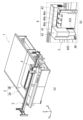
- FIG. 1 is a diagram for explaining a cutting plotter 1.
- Fig. 1(a) is a perspective view of the cutting plotter 1.
- Fig. 1(b) is an enlarged view of the periphery of a processing unit 4 of the cutting plotter 1.
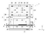
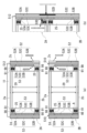
- Fig. 2 is a plan view seen from above of the cutting plotter 1.
- legs 24, frames 25, 29, etc. located on the rear side of the page of the table 2B are shown by virtual lines in order to explain their positions.
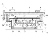
- FIG. 3 is a schematic cross-sectional view of the cutting plotter 1 taken along line AA in FIG.
- Figures 4 and 5 are cross-sectional views of the main part of the cutting plotter 1.
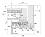
- Figure 4(a) shows a cross-section in which an area A in Figure 3 is enlarged
- Figure 5 shows a cross-section in which an area B in Figure 3 is enlarged.
- the casters 91 for moving the cutting plotter 1 and the stoppers 98 for positioning may be omitted.
- the detachable guide rails 52A, 52B, the fixed guide rail 52C, and the connecting guide rail 52D when there is no particular distinction between the detachable guide rails 52A, 52B, the fixed guide rail 52C, and the connecting guide rail 52D, they may be simply referred to as guide rails 52.
- the detachable rack rails 53A and 53B, the fixed rack rail 53C, and the connecting rack rail 53D they may be simply referred to as rack rails 53.
- the symbol "Y” in each drawing indicates the main scanning direction in the cutting plotter 1.
- the symbol “X” indicates the sub-scanning direction in the cutting plotter 1.
- the symbol “Z” indicates the vertical direction based on the installation state of the cutting plotter 1. In the following description, the positional relationship of each component of the cutting plotter 1 will be described using the X, Y, and Z directions in FIG. 1 as necessary.
- the X direction and the Y direction are directions perpendicular to each other and are horizontal directions along the upper surface of the table 2.
- the Z direction is a vertical line direction based on the installation state of the cutting plotter 1, and is a direction perpendicular to both the X direction and the Y direction.
- the cutting plotter 1 has a table 2 on which the workpiece T is placed, a support beam 3 (Y bar) arranged horizontally above the table 2 in a direction along the Y direction, a processing unit 4 supported by the support beam 3 and movable in the longitudinal direction (Y direction) of the support beam 3, a drive mechanism 5 (5A, 5B) that moves the support beam 3 in the X direction, and a drive mechanism 5C that moves the processing unit 4 back and forth in the Y direction along the support beam 3.
- a support beam 3 Y bar
- a processing unit 4 supported by the support beam 3 and movable in the longitudinal direction (Y direction) of the support beam 3
- a drive mechanism 5 (5A, 5B) that moves the support beam 3 in the X direction
- a drive mechanism 5C that moves the processing unit 4 back and forth in the Y direction along the support beam 3.
- the table 2 shown in FIG. 1 is configured by connecting a table 2A equipped with a control panel 11 and an extension table 2B not equipped with the control panel 11 in the X direction.
- Fig. 1 illustrates an example in which there is one expansion table 2B.
- the total number of expansion tables 2B is not limited to the embodiment shown in Fig. 1.
- the table 2 of the cutting plotter 1 can be expanded in the X direction according to the size of the workpiece T by increasing the total number of tables 2B to be connected. In the following description, unless there is a need to distinguish between Tables 2A and 2B, they will simply be referred to as Table 2.
- the table 2 (2A, 2B) has a rectangular shape when viewed from above.
- the table 2 has a table base 20 with an open top, and a table top 21 that covers the opening of the table base 20 .
- the table base 20 has a bottom wall portion 201 and a peripheral wall portion 202 surrounding the outer periphery of the bottom wall portion 201.
- an internal space 23 is formed between the table base 20 and the table top 21.
- the upper surface of the table top 21 serves as a mounting surface 21a on which the workpiece T is placed.
- the workpiece T is, for example, cardboard, a medium on which information such as letters or patterns is printed, a medium made of resin such as acrylic, a paper container, a channel material for a signboard, or the like.
- the support surface 21a has a plurality of suction holes 210 (communication holes) over almost the entire surface.
- the internal space 23 of the table 2 is connected to the outside via the suction holes 210 provided in the table top 21.
- a connection port 201a is provided on the bottom wall portion 201 of the table base 20.
- a connector 32 connected to an end of a pipe 31 is fitted and fixed in the connection port 201a.
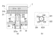
- the connector 32 has a cylindrical base 321 and a flange portion 322 that surrounds the entire outer periphery of the base 321 .
- the flange portion 322 bulges outward in the radial direction from the outer periphery of the base portion 321 on the side of one end portion 321 a.
- An end 321 a of the base 321 is open.
- the end 321 a side of the base 321 is fitted into the pipe 31 on the outside of the bottom wall 201.
- the other end 321b of the base 321 is sealed with a disk-shaped cap 323. Therefore, the base 321 has a cylindrical shape with a bottom.
- the end 321b side of the base 321 is inserted into the internal space 23 through the connection port 201a.
- the end 321b of the base 321 faces the table top 21 in the internal space 23 with a gap in the Z direction therebetween.
- the connector 32 has a flange portion 322 provided on the outer periphery of the base portion 321 abutting against the peripheral edge of the connection port 201a in the bottom wall portion 201.
- a seal ring S is provided on the flange portion 322 at the portion facing the bottom wall portion 201. The seal ring S seals the gap between the flange portion 322 and the bottom wall portion 201.
- a communication hole 324 (through hole) that connects the inside and outside of the base 321 is provided in a region of the base 321 that is located within the internal space 23 .
- the communication hole 324 is an elongated hole extending along the longitudinal direction of the base portion 321 (the up-down direction in FIG. 4A ).
- 4B when viewed from the opening direction of the connection port 201a, the communication holes 324 are provided at intervals in the circumferential direction around the central axis X321 of the base 321.
- four communication holes 324 are provided at 90° intervals in the circumferential direction around the central axis X321.
- a switching valve 33 is provided in the pipe 31 to which the connector 32 is connected.
- the two connectors 32, 32 are connected to a pipe 35 in which a blower 34 is provided via one switching valve 33.
- the blower 34 When the blower 34 is driven, an air flow is formed from one side of the blower 34 to the other side.
- the blower 34 forms an air flow from the internal space 23 of the table 2 toward the blower 34 inside the pipe 31, and generates a pressure state (negative pressure state) lower than atmospheric pressure in the internal space 23. Then, air is drawn into the internal space 23 through the suction holes 210 opening in the mounting surface 21a of the table 2. Due to this air flow, a suction force (negative pressure) is generated in the suction holes 210 in the mounting surface 21a of the table 2.
- the workpiece T placed on the table 2 is sucked onto the support surface 21a of the table 2 by the suction force generated by driving the blower 34, and is held in a state in which movement in the horizontal direction (X direction, Y direction) and the vertical direction (Z direction) is restricted.
- four connectors 32 are provided on one table 2, and communication between each connector 32 and the blower 34 is switched on/off by operating a changeover valve 33. Therefore, the area on the table 2 where negative pressure is generated can be changed depending on the size of the workpiece T placed on the table 2.
- the other end 321b of the base 321 of the connector 32 is sealed with a disk-shaped cap 323.
- the cap 323 is located on an extension of the opening direction of one end 321a of the base 321 (the up-down direction in FIG. 4A). Therefore, when viewed from the vertical direction, the cap 323 and the opening of one end 321a are arranged in an overlapping positional relationship.
- the opening at one end 321a is an inlet for air to be sucked into the pipe 31. If the other end 321b is open, the flow of air sucked into the pipe 31 will be most likely in the direction along the longitudinal direction of the base 321.
- the suction force generated in the table top 21 is greatest in the area overlapping with the connector 32 when viewed from the Z direction, and the suction force decreases as the area moves away from this area. In other words, the suction force generated in the table top 21 varies.
- the other end 321b of the base 321 is sealed with a disk-shaped cap 323. Therefore, the air in the internal space 23 flows into the inside of the base 321 through a long hole-shaped communication hole 324 that opens into the side of the base 321, and is then sucked into the piping 31 side. As a result, when viewed from the vertical direction, air is sucked in approximately evenly from the peripheral area of the connector 32 to the connector 32 side. This reduces the variation in the suction force generated in the table top 21 compared to when the cap 323 is not provided.
- the suction force generated on the table 2 restricts the movement of the workpiece T in the horizontal directions (X direction, Y direction) and the vertical line (Z direction), and the workpiece T is processed using a tool held by the processing unit 4, which will be described later.
- the support beam 3 supporting the processing unit 4 is disposed horizontally above the table 2.
- the support beam 3 has a length that crosses the table 2 in the Y direction.
- a processing unit 4 is mounted on the support beam 3.
- the processing unit 4 is supported on the support beam 3 so as to be movable in the longitudinal direction (Y direction) of the support beam 3.
- a drive mechanism 5C including a resin belt V and a motor Ma for moving the belt V is attached to the support beam 3, and the processing unit 4 moves forward and backward in the Y direction by being driven by the drive mechanism.
- the support beam 3 has a pair of support columns 39, 39.
- the support columns 39, 39 are located on both sides of the table 2 in the Y direction, and cross the sides of the table base 20 below in the Z direction.
- the lower ends of the support columns 39, 39 are connected to sliders 55, 55 of the drive mechanisms 5 (5A, 5B), respectively.
- the support beam 3 is moved in the X direction by drive mechanisms 5A, 5B provided on both sides of the lower side of the table base 20.
- the drive mechanisms 5A and 5B have the same basic configuration, so in the following, the configuration of the drive mechanism 5B will be described as a representative example.
- the drive mechanism 5B includes a holder 51, a guide rail 52, a rack rail 53, a slider 55, and a motor M.
- the holder 51 is a columnar member fixed to the lower part of the table base 20. When viewed from the X direction, the holder 51 has a width W51 in the Y direction that is substantially the same as that of the peripheral wall portion 202 of the table base 20.
- FIG. 6 is a cross-sectional view of the driving mechanism 5B taken along line AA in FIG. 5, showing a cross-sectional view of the main part of the driving mechanism 5B.
- Figure 7 is a cross-sectional view of the main part of the portion related to the connection of the table in the cutting plotter 1.
- (a) of Figure 7 is a cross-sectional view of the table 2A taken along the line B-B in Figure 2.
- (b) of Figure 7 is a cross-sectional view of the table 2A taken along the line CC in Figure 2.
- Fig. 8 is a diagram for explaining the table 2.
- Fig. 8(a) shows a schematic diagram of the tables 2A and 2B connected to each other, as viewed from below the installation surface G.
- Figure 9 is a cross-sectional view of the main part of the portion related to the connection of the tables in the cutting plotter 1.
- Figure 9(a) is a cross-section along the line A-A in Figure 7(a) and shows the connection portion between the tables 2A and 2B.
- Figure 9(b) is a cross-section along the line B-B in Figure 7(a) and shows the connection portion between the tables 2A and 2B.
- Figure 9(c) is a cross-section along the line C-C in Figure 7(a) and shows the connection portion between the tables 2A and 2B.
- the holder 51 is formed with a length L51 in the X direction that extends from one side edge 2a of the table 2 to the other side edge 2b.
- a guide rail 52 and a rack rail 53 are provided at a distance in the Y direction below the holder 51.
- the guide rail 52 and the rack rail 53 have a substantially rectangular shape.
- a protruding portion 512 that protrudes downward is provided on the lower portion of the holder 51.
- side surfaces 512c and 512d of the protruding portion 512 are flat surfaces that extend along the vertical line (Z direction).
- the rack rail 53 abuts against the side surface 512c located on the inside (left side in FIG. 5) of the table 2 from the Y direction. In this state, the rack rail 53 is positioned so that the outer periphery with which the gear 57 meshes protrudes further inward (left side in the drawing) than the holder 51.
- a fixing rail 54 abuts against the rack rail 53 from below in the Z direction.
- the rack rail 53 is fixed to the bottom of the holder 51 by a bolt (not shown) that passes through the rail 54 and the rack rail 53 in the vertical direction.
- the guide rail 52 is disposed on the outer side (the right side in the figure) of the protruding portion 512 with a gap between it and the protruding portion 512.
- the guide rail 52 is also fixed to the lower portion of the holder 51 by a bolt (not shown).
- a concave rail member 56 fixed to the upper surface of the slider 55 engages with the guide rail 52 from below in the Z direction.
- the rail member 56 engages with the guide rail 52 so as to be movable in the longitudinal direction of the guide rail 52 while being prevented from falling off the guide rail 52.
- the rail member 56 is fixed to the upper surface of the plate-shaped slider 55.
- the slider 55 is provided with a connecting pillar 551 on the outer side (right side in the figure) when viewed from the rail member 56.
- the pillar 551 protrudes upward in the Z direction.
- the pillar 551 engages with the engagement hole 390 at the bottom of the support pillar 39 from the Z direction.
- the support pillar 39 is connected to the slider 55 while placed on the slider 55.
- the slider 55 has a length L55 in the Y direction crossing below the holder 51 toward the center side (left side in the figure) of the table 2.
- a notch 55c is provided on the tip 55a side of the slider 55 for inserting the shaft SH of the motor M therethrough.
- the motor M is fixed to the lower surface of the slider 55, and the shaft SH passes through the notch 55c upward.
- the upper end side of the shaft SH is connected to a gear 57.
- the gear 57 meshes with the outer periphery of the rack rail 53.
- the cutting plotter 1 has driving mechanisms 5A and 5B on both sides of the table 2 in the Y direction. By driving these driving mechanisms 5A and 5B in a synchronized manner, the support beam 3 moves in the X direction.
- the rack rail 53, the protrusion 512 of the holder 51, and the guide rail 52 are aligned in the Y direction.
- the guide rails 52 and the rack rails 53 are provided in a range extending in the X direction (the up-down direction in the drawing) from a side edge 2a at one end of the table 2 (table base 20) to a side edge 2b at the other end.
- the guide rail 52 has removable guide rails 52A, 52B (detachable rails) provided on the side edges 2a, 2b, and a fixed guide rail 52C (fixed rail) located between the removable guide rails 52A, 52B.
- the guide rail 52 is configured by connecting in series a removable guide rail 52A, a fixed guide rail 52C, and a removable guide rail 52B.
- the detachable guide rails 52A, 52B are attached with bolts (not shown) to the table base 20.
- the detachable guide rails 52A, 52B are detachable guide rails that are intended to be detached from the table base 20 when the tables 2A, 2B are coupled to each other.
- the fixed guide rail 52C is fixed to the table base 20 with bolts (not shown).
- the fixed guide rail 52C is a guide rail that remains fixed to the table base 20 when the tables 2A, 2B are connected to each other.
- the rack rail 53 includes detachable rack rails 53A, 53B (detachable rails) provided on the side edges 2a, 2b, and a fixed rack rail 53C (fixed rail) located between the detachable rack rails 53A, 53B.
- the rack rail 53 is configured by connecting in series a detachable rack rail 53A, a fixed rack rail 53C, and a detachable rack rail 53B.
- the detachable rack rails 53A, 53B are attached with bolts (not shown) to the table base 20.
- the detachable rack rails 53A, 53B are detachable rack rails that are intended to be detached from the table base 20 when the tables 2A, 2B are coupled to each other.
- the fixed rack rail 53C is fixed to the table base 20 with bolts (not shown).
- the fixed rack rail 53C is a rack rail that remains fixed to the table base 20 when the tables 2A, 2B are connected to each other.
- the end 53b of the fixed rack rail 53C is disposed at a position offset by a length L53 in the X direction from the side edge 2b of the table 2A (table base 20). Furthermore, the end 52b of the fixed guide rail 52C is provided at a position offset by a length L52 in the X direction from the side edge 2b of the table 2A.
- the end 53a of the fixed rack rail 53C and the end 52a of the fixed guide rail 52C are provided at positions offset by lengths L53 and L52, respectively, from the side edge 2a of the table 2B in the X direction.
- end 53b of fixed rack rail 53C and end 52b of fixed guide rail 52C are offset in the X direction from side edge 2b of table 2B by lengths L53 and L52, respectively (see Figures 9(a) and (c)).
- a protrusion 510 is provided on the side edge 2a of the table 2B.
- the protrusion 510 is a cylindrical portion with a spherical tip.
- the protrusion 510 is detachable from the mounting portion 513 of the holder 51 (see Fig. 9B).
- a mounting portion 513 is also provided on the side edge 2a of the table 2A.
- the projection 510 extends in the X direction along an extension of the protruding portion 512 of the holder 51 .
- An engagement hole 511 is provided in the side edge 2b of the table 2A.
- the engagement hole 511 is a cylindrical hole with a bottom into which a protrusion can be inserted.
- the engagement hole 511 When viewed from the Z direction, the engagement hole 511 extends in a direction away from the side edge 2b along the protrusion 512 of the holder 51.
- the projections 510 of the table 2B are inserted into the engagement holes 511 on the table 2A side from the X direction.
- an identically configured engagement hole 511 is provided on the side edge 2b of table 2B.
- a protrusion 510 on the other table 2B is inserted into the engagement hole 511 of table 2B.
- the holders 51 are attached to the lower portions of both sides in the Y direction of the table 2. Therefore, the protrusions 510 of the table 2B are provided on each of the holders 51 located on both sides in the Y direction.
- the engagement holes 511 are also provided on each of the holders 51.
- one of the two engagement holes aligned in the Y direction, engagement hole 511 is formed in a circular cross section with an inner diameter Da that matches the outer diameter of protrusion 510 (see FIG. 7A).
- the other engagement hole 511A has an inner diameter Da in the Z direction that is the same as that of engagement hole 511, but an inner diameter Db in the Y direction that is larger than the inner diameter D of engagement hole 511.
- the engagement hole 511A When viewed from the X direction, the engagement hole 511A has an elongated hole shape whose length in the Y direction is longer than its length in the Z direction.
- the table 2 has four legs 24 that support the table 2 from below.
- the four legs 24 are spaced apart from one another in the X and Y directions. These legs 24 are disposed at positions away from the side edges 2c, d of the table 2 toward the center of the table 2 in order to avoid interference with the gear 57 of the drive mechanism 5 (5A, 5B) (see Fig. 3).
- the legs 24 on one side in the Y direction (left-right direction in FIG. 3 ) and the legs 24 on the other side are connected by a frame 26 extending in the Y direction.
- the frame 26 is provided at a position spaced above the installation surface G of the table 2 and oriented along the horizontal line.
- the legs 24, 24 on the side edge 2c side and the legs 24, 24 on the side edge 2d side are connected to each other by frames 25, 25 extending in the X direction. These frames 25, 25 are also provided at positions spaced above the installation surface G of the table 2 and oriented along the horizontal line.
- a side cover 30 is provided across the legs 24, 24 on the side edge 2d (see FIG. 3).
- the side cover 30 is provided to cover the opening between the legs 24, 24 on the side edge 2d, the frame 25, and the table base 20, and to improve the support strength of the table 2.
- the side cover 30 is provided as a vibration suppression member that suppresses vibration of the table 2, particularly vibration in the X direction.
- the frame 26 is connected to a frame 29 at its middle in the Y direction. As shown in Fig. 2, the frame 29 is provided across the frame 26 on the side edge 2a side of the table and the frame 26 on the side edge 2b side of the table. The frame 26 is disposed parallel to the frames 25, 25.
- diagonal braces 28, 28 are provided on the upper side of the frame 26. The diagonal braces 28, 28 are each inclined in a direction approaching the table base 20 as they move away from the leg 24. The upper ends of the diagonal braces 28, 28 are each connected to a connecting portion 27 attached to the underside of the table base 20. The diagonal braces 28, 28 are provided in a symmetrical positional relationship with the connecting portion 27 in between.
- the diagonal braces 28, 28 and the connecting portion 27 are provided on the side edge 2a side and the side edge 2b side of the table 2, respectively.
- the diagonal braces 28, 28 and the connecting portion 27 are provided to suppress vibration of the table 2 in the longitudinal direction (Y direction) of the support beam 3, and are provided as vibration suppression members that suppress vibration of the table 2 in the Y direction.
- the processing unit 4 supported by the support beam 3 moves at a speed faster than a carriage in an inkjet printing device.
- vibrations caused by the displacement of the processing unit 4 act on the table 2. Therefore, in the cutting plotter 1, in order to increase the resistance of the table 2 to vibrations generated when processing the workpiece T, frames 25, 25, 26 spanning the legs 24, 24, a frame 29 connecting the frames 26, 26 together, diagonal braces 28, 28 spanning the legs 24 and the table base 20, and a side cover 30 are arranged to increase the resistance of the processing unit 4 to vibrations.
- the side cover 30 which has not been adopted in inkjet printing devices, it is possible to suitably suppress shaking (vibration) caused by the movement of the processing unit 4 in the cutting plotter 1.
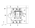
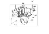
- FIGS. 10 and 11 are diagrams illustrating casters 91 for movement and stoppers 98 for positioning.
- Fig. 10 is an enlarged view of region A in (a) of Fig. 8.
- Fig. 11 is a perspective view of the caster 91 provided at the lower end of the leg 24 as viewed obliquely from below.
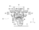
- Fig. 12 is a cross-sectional view of the caster 91.
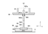
- Fig. 13 is a cross-sectional view of the stopper 98.
- Fig. 12 is a schematic cross-sectional view of the caster 91 taken along line A-A in Fig. 10.
- Fig. 13 is a schematic cross-sectional view of the stopper 98 (see Fig. 13) taken along line B-B in Fig. 10.
- a flange portion 241 extending horizontally is provided at the lower end of the leg portion 24.
- a support plate 90 is fixed to the lower surface of the flange portion 241 by bolts (not shown).
- a caster 91 and a stopper 98 are attached to the support plate 90.
- the wheels 910 of the caster 91 are rotatably supported by a support shaft 912 provided on a fork portion 911 (first support portion). Both ends of the support shaft 912 are supported by a pair of support plates 911a, 911a (see FIG. 10 ) provided on the fork portion 911.
- the support shaft 912 is provided along an axis XH (horizontal line) parallel to the installation surface G of the table 2.
- the wheel 910 is rotatable around the axis XH.
- the axis XH is parallel to the X direction and the Y direction.
- a cylindrical support tube 913 is provided on the upper part of the fork portion 911.
- the outer periphery of the support tube 913 is rotatably supported by a holder 914 via a bearing 915. This allows the fork portion 911 to rotate around an axis V1 that is aligned along a vertical line.
- the holder 914 is fixed to the lower surface of a bottom portion 961 of the bracket 96.
- the bottom portion 961 has a generally rectangular shape in a plan view. Both side portions of the bottom portion 961 in the left-right direction in the figure are bent toward the support plate 90 to form side wall portions 962, 962 extending toward the support plate 90.
- the side wall portions 962, 962 are provided parallel to each other.
- a connecting plate 963 is fixed to the upper surface of the bottom portion 961 on the side of the support plate 90.
- the connecting plate 963 is provided with a cylindrical boss portion 964 along the axis V1.
- the boss portion 964 is formed so as to rise upward from the connecting plate 963 on the side of the support plate 90.
- a screw thread is provided on the inner periphery of the boss portion 964.
- the boss portion 964 is provided with an opening of the boss portion 964 oriented along the axis V1.
- One end of a rod-shaped shaft member 965 is screwed into the boss portion 964. In this state, the shaft member 965 is connected to the connecting plate 963 and the bracket 96 so as not to rotate relatively to each other.
- a screw thread 965a is provided on the outer periphery of the shaft member 965 over the entire length in the longitudinal direction.
- the support plate 90 side of the shaft member 965 passes through a through hole 901 provided in the support plate 90.
- a screw thread 901a is provided on the inner periphery of the through hole 901.
- the shaft member 965 having the screw thread 965a and the screw thread 910a on the support plate 90 side, which is the fixed member, constitute a screw feed mechanism. Therefore, when the bracket 96 is gripped and rotated around the axis V1, the bracket 96, the holder 914, the fork portion 911, and the wheel 910 are displaced integrally in the direction of the axis V1.
- the direction of displacement at this time is one direction along the axis V1 that is determined according to the direction of rotation of the bracket 96.
- the casters 91 attached to the legs 24 of the table 2 can be adjusted in position in the vertical direction (Z direction). Therefore, by adjusting the position of the casters 91, the height of the table 2 (table top 21, table base 20) can be adjusted.
- a positioning nut 966 is provided between the support plate 90 and the connecting plate 963 of the shaft member 965. After completing the position adjustment of the caster 91 in the vertical line direction (Z direction), the positioning nut 966 is rotated to abut against the lower surface of the support plate 90, whereby the rotation of the shaft member 965 can be restricted.
- positioning brackets 97, 97 are attached to the underside of the support plate 90.
- the positioning bracket 97 has a fixing portion 971 that is fixed to the underside of the support plate 90 with a bolt, and a connecting portion 972 that extends from the fixing portion 971 in a direction away from the support plate 90 along the axis V1.
- the positioning brackets 97 are provided in a symmetrical positional relationship with respect to the shaft member 965.
- the side walls 962, 962 of the bracket 96 described above are inserted between the connecting parts 972 that are spaced apart in the horizontal direction (left-right direction in the figure).
- a long hole 972a is provided in the connecting portion 972 so as to be oriented along the axis V1.
- a plurality of the long holes 972a are provided at intervals in the Y direction.
- the side walls 962, 962 of the bracket 96 are positioned by being gripped between a connecting portion 972 and a nut Nb by a screw Na and a nut Nb which pass through an elongated hole 972a (see FIG. 12).
- casters 91 are provided at the four corners of the table 2 when viewed from above (see FIG. 8). Therefore, by adjusting the positions of the casters 91, the height and inclination of the table 2 can be adjusted.
- the support plate 90 is provided with a stopper 98 at a position adjacent to the caster 91 described above.
- the stoppers 98 on the table 2 are located on the side edges 2c and 2d of the table 2 in the Y direction when viewed from the casters 91.
- the stopper 98 is an integral part having a disk-shaped contact portion 981 and a shaft member 985 connected to the contact portion 981.
- the stopper 98 is provided in a direction along an axis V2 that is parallel to the axis V1.
- the shaft member 985 extends linearly from the center of the contact portion 981 along the axis V2 in a direction away from the contact portion 981.
- a screw thread 985b is provided on the outer periphery of an end portion 985a of the shaft member 985 opposite the contact portion 981.
- An end 985a side of the shaft member 985 passes through a through hole 902 provided in the support plate 90.
- a screw thread 902a is provided on the inner circumference of the through hole 902.
- the shaft member 985 having the screw thread 985b and the screw thread 902a on the support plate 90 side, which is the fixed member, constitute a screw feed mechanism. Therefore, when the stopper 98 is gripped and rotated around the axis V2, the stopper 98 is displaced in the direction of the axis V2. The direction of displacement at this time is one direction along the axis V2, which is determined according to the rotation direction of the stopper 98.
- a resin holder 99 is interposed between the abutment portion 981 of the stopper 98 and the installation surface G.
- the holder 99 has a body portion 990 having a substantially rectangular shape in a plan view.
- An elastic member 995 such as rubber is attached to the entire surface of the body portion 990 facing the installation surface G.
- a recess 991 is provided on the surface of the main body 990 facing the support plate 90, the recess 991 being recessed toward the installation surface G.
- the recess 991 is a generally cylindrical recess having an inner diameter that generally matches the outer diameter D981 of the contact portion 981 of the stopper 98.
- a positioning nut 986 is provided in the shaft member 985 between the support plate 90 and the abutment portion 981. After completing the position adjustment of the stopper 98 in the vertical line direction (Z direction), the positioning nut 986 is rotated to abut against the lower surface of the support plate 90, whereby the rotation of the shaft member 985 can be restricted.
- the table 2B is positioned so that the projection 510 on the table 2B side faces the engagement holes 511, 511A (see FIGS. 6 and 7) on the table 2A side in the X direction.
- the table 2B is brought closer to the table 2A in the X direction, and the protrusions 510, 510 on the table 2B side are inserted into the engagement holes 511, 511A on the table 2A side (see FIG. 7).
- a protrusion 510 having an outer diameter that matches the inner diameter of one of the engagement holes 511 is inserted into this engagement hole 511, thereby positioning the connected table 2B in the Y direction based on the side of the table 2A on which the engagement hole 511 is provided. Since the inner diameters of the engagement holes 511 and 511A in the Z direction are the same, positional accuracy in the Z direction is ensured.
- a projection 510 provided on one of the tables 2 to be connected and an engagement hole 511 provided on the other table 2 constitute a connection mechanism 500 in the present invention.
- the fixed guide rails 52C and fixed rack rails 53C of table 2A face the fixed guide rails 52C and fixed rack rails 53C of table 2B with a gap in the X direction.
- the cutting plotter 1 has a connecting guide rail 52D that closes the gap between the fixed guide rails 52C, 52C of adjacent tables, and a connecting rack rail 53D that closes the gap between the adjacent fixed rack rails 53C, 53C.
- connecting guide rail 52D and connecting rack rail 53D are positioned across tables 2A and 2B, thereby forming continuous guide rails and rack rails across tables 2A and 2B.
- the projections 510, 510 of one table 2B are inserted into the engagement holes 511, 511A (recesses) of the other table 2A, thereby completing the connection between the tables 2A and 2B.
- the table 2B can be easily moved, and the time required to connect the tables 2A and 2B to each other is shortened. As a result, even if the total number of tables 2 to be linked increases, the time required to link the tables 2 together does not increase significantly, so the total number of tables can be easily increased.
- the processing unit 4 has a main body portion 41 that is placed on the support beam 3 .
- the fixed unit 42 and the holder unit 43 are adjacent to each other in the Y direction.
- An upper surface 43a of the holder unit 43 is located lower than the fixed unit 42 in the Z direction.
- the slots 44a to 44c are provided closer to the fixed unit 42, and the slots 44a to 44c are aligned in the Y direction.
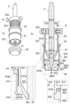
- Fig. 14 is a diagram for explaining the fixing unit 42.
- Fig. 14(a) is an enlarged perspective view showing the periphery of a jig 40 for mounting the pen holder 6 in the fixing unit 42.
- Fig. 14(b) is a perspective view showing a state in which the pen holder 6 is mounted on the jig 40.
- Fig. 15 is a diagram for explaining the pen holder 6.
- Fig. 15(a) is a perspective view of the pen holder 6 as viewed obliquely from below.
- Fig. 15(b) is a cross-sectional view of the pen holder 6.
- the fixing unit 42 has an area on the holder unit 43 side that bulges in the X direction.
- a camera housing section 421 is provided below this bulging area.
- a camera unit (not shown) is housed inside the camera housing section 421, facing downward in the Z direction.
- a support unit 422 that supports a jig 40 is provided next to the camera housing portion 421.
- the jig 40 is a jig for mounting a pen holder 6, which will be described later.
- the jig 40 has an annular mounting portion 401 and a positioning screw 402.
- the mounting portion 401 is fixed to the front of the plate-shaped base 400.
- the mounting portion 401 is provided with its opening facing the Z direction.
- a holder 403 for the screw 402 is attached to the front of the mounting portion 401.
- the shaft portion (not shown) of the screw 402 passes through the holder 403 and the mounting portion 401.
- the tip of the shaft portion of the screw 402 can appear and disappear from the inner circumference of the mounting portion 401 in conjunction with the rotation of the screw 402.
- the cylindrical base 61 of the pen holder 6 is inserted from above in the Z direction into the mounting part 401. In this state, the tip of the shaft of the screw 402 is pressed against the outer periphery of the base 61, thereby fixing the pen holder 6 to the mounting part 401.
- the pen holder 6 is a jig for holding a writing implement such as a drafting pen.
- the pen holder 6 has a cylindrical base 61, a support 62 for supporting the pen P, a lock nut 63, and a cap 65.
- the base portion 61 has a cylindrical peripheral wall portion 610.
- the peripheral wall portion 610 has an outer diameter D61 that matches the inner diameter of the mounting portion 401 described above.
- a ring-shaped support portion 611 is provided on the inner circumference of the peripheral wall portion 610.
- a plate 612 made of a magnetic material such as iron is attached to the portion of the support portion 611 facing the cap 65.
- the cap 65 has a cylindrical fitting portion 653 that fits into the end 610a of the pen holder 6 from the direction of the central axis C6 of the pen holder 6.
- a magnet 654 is provided at the end of the fitting portion 653.
- a plurality of magnets 654 are provided at predetermined intervals in the circumferential direction around the central axis C6.
- the cap 65 is formed into a cylindrical shape with a bottom, and is made up of a bottom wall portion 651 and a cylindrical peripheral wall portion 652 that surrounds the outer periphery of the bottom wall portion 651.
- the tip of the peripheral wall portion 652 serves as a fitting portion 653 that fits into the base portion 61.
- the fitting portion 653 is formed with an outer diameter larger than an outer diameter D652 of the peripheral wall portion 652.
- a flange portion 655 is provided on the outer periphery of the fitting portion 653.
- the flange portion 655 protrudes radially outward from the outer periphery of the peripheral wall portion 652.
- the flange portion 655 is provided over the entire circumferential direction around the central axis C6.
- the end 610a of the base 61 comes into contact with the flange 655 from the direction of the central axis C6. Furthermore, the magnet 654 provided in the fitting portion 653 is magnetically attached to the plate 612 on the base 61 side, so that the cap 65 is held in a state where it is magnetically attached to the base 61.
- the base 61 has an engagement portion 613 on the other end 610b side of the peripheral wall portion 610 (upper side in FIG. 15(b)).
- the engagement portion 613 is formed by bulging out from the inner circumference of the peripheral wall portion 610 toward the inner diameter side.
- the engagement portion 613 is formed with the same thickness all around the circumferential direction around the central axis C6 of the pen holder 6.
- a screw groove 613a is provided on the inner circumference of the engagement portion 613.
- the screw groove 613a of the engagement portion 613 screws into the screw groove 621c on the support portion 62 side.
- the support portion 62 has a tube portion 621, a core alignment portion 622, and a screw support portion 624.
- the tube portion 621 is a cylindrical portion formed with an inner diameter D621 into which the pen P can be inserted.
- a screw groove 621c is provided on the outer periphery of the tube portion 621 over the entire length in the longitudinal direction (the direction of the central axis C6).
- the cylindrical portion 621 has an end 621a on one side in the direction of the central axis C6, to which a centering portion 622 is connected.
- the core alignment portion 622 is formed in a tapered shape such that an inner diameter D622 decreases with increasing distance from the tube portion 621.
- a bottom wall portion 623 is provided at the lower end of the core alignment portion 622.
- the bottom wall portion 623 is provided in a direction perpendicular to the central axis C6 of the pen holder 6.
- the bottom wall portion 623 has a through hole 623a having an inner diameter sufficient for the pen P to be inserted therethrough.
- the through hole 623a is formed with an inner diameter D633 that matches the outer diameter of the pen P.
- the through hole 623a penetrates the bottom wall portion 623 in the Z direction (the up-down direction in the figure) at a position that is concentric with the central axis C6 of the pen holder 6.
- the pen tip P1 When the pen P is inserted with the pen tip P1 side through this through hole 623a and fitted into the through hole 623a, the pen tip P1 is positioned on the central axis C6 of the pen holder 6.
- the inclination of the core alignment portion 622 with respect to the central axis C6 is provided to facilitate the guidance of the pen tip P1 side into the through hole 623a.
- the support portion 62 of the pen holder 6 can be changed depending on the type of pen P to be used. In this case, multiple support portions 62 with different opening diameters of the through hole 623a are prepared, and a support portion 62 having a through hole 623a with an appropriate opening diameter can be selected depending on the type of pen P. This is expected to reduce costs compared to preparing the entire pen holder 6 for each type of pen P.
- the screw support portion 624 is connected to the other end portion 621b of the cylindrical portion 621.
- the screw support portion 624 is a cylindrical portion that completely surrounds the central axis C6.
- the screw support portion 624 is formed with an outer diameter D624 that is larger than that of the cylindrical portion 621.
- the screw support portion 624 is disposed concentrically with the cylindrical portion 621.
- the screw support portion 624 is provided with positioning screws N at predetermined intervals in the circumferential direction around the central axis C6.
- the shaft portion N1 of the screw N penetrates the screw support portion 624 in the thickness direction (radial direction of the central axis C6).
- the tip of the shaft portion N1 engages with a pressing piece 625 arranged on the inside of the screw support portion 624.
- three screws N are arranged at predetermined intervals in the circumferential direction around the central axis C6.
- the pressing piece 625 moves forward and backward in the axial direction of the shaft portion N1 of the screw N.
- the pen P is inserted into the inside of the tube portion 621 from the screw support portion 624 side.
- the pen tip P1 side of the pen P is fitted into the through hole 623a of the bottom wall portion 623, and the pen P is arranged concentrically about the central axis C6.
- the pressing piece 625 and the screw N are provided to hold the pen P in an orientation along the central axis C6.
- the pressing piece 625 With the pen tip P1 side disposed on the central axis C6, the pressing piece 625 is brought into contact with the outer periphery of the base end side of the pen P for positioning, so that the pen P can be disposed in an orientation along the central axis C6 over its entire length in the longitudinal direction.
- the engaging portion 613 of the base portion 61 and the lock nut 63 are screwed into a thread groove 621c on the outer periphery of the cylindrical portion 621.
- the support portion 62 having the cylindrical portion 621, the base portion 61 and the lock nut 63 are capable of relative rotation about a central axis C6. Therefore, when the support part 62 having the tube part 621 is rotated relative to the base part 61 about the central axis C6, the support part 62 and the base part 61 are relatively displaced in the direction of the central axis C6.
- the amount of protrusion (height h) of the pen tip P1 of the pen P from the end part 610a of the peripheral wall part 610 on the base part 61 side can be adjusted.
- the lock nut 63 is provided to restrict the relative rotation of the support portion 62 with respect to the base portion 61.
- the lock nut 63 restricts the rotation of the tubular portion 621 of the support portion 62, the relative displacement of the support portion 62 and the base portion 61 in the direction of the central axis C6 is restricted.
- the lock nut 63 is provided to maintain the amount of protrusion (height h) of the nib P1 of the pen P from the end portion 610a of the peripheral wall portion 610.
- the cap 65 is attached to the end portion 610 a of the peripheral wall portion 610 by utilizing the magnetic force of the magnet 654 .
- the relative rotation direction of the support portion 62 with respect to the base 61 is a direction that causes the pen tip P1 to protrude from the peripheral wall portion 610, the cap 65 will move slightly away from the peripheral wall portion 610 when the pen tip P1 exceeds a predetermined height h from the end portion 610a of the peripheral wall portion 610.
- the positional relationship between the fitting portion 653 (magnet 654) of the cap 65 and the bottom wall portion 651 in the direction of the central axis C6 is set so that the cap 65 separates from the peripheral wall portion 610 when the pen tip P1 reaches a position where the pen tip P1 protrudes by a height h from the end portion 610a of the peripheral wall portion 610. Therefore, the protruding height of the pen tip P1 can be adjusted visually in addition to being actually measured.
- Figure 16 is a diagram explaining an example of how to use slots 44a to 44c of the processing unit 4.
- unused slots 44a to 44c are aligned in the Y direction.
- the support units 7 of the tool can be detachably attached to each of the slots 44a to 44c.
- the support unit 7A is attached to the slot 44a.
- the support unit 7B attached to the slot 44b is shown in a position spaced apart from the processing unit 4.
- the support unit 7B has an insertion leg 72 that is inserted into the slot 44b.
- the insertion leg 72 extends downward from the lower part of the main body 71.
- the main body 71 houses a drive mechanism such as a motor for driving the tool inside.
- the support unit 7 is attached to the holder unit 43 by inserting the insertion legs 72 into the slots 44, and the drive mechanism inside the main body 71 is connected to the power supply source.
- the main body 71 has a range in the Z direction that extends to the front side of the insertion leg 72.
- a tool holder 74 is supported on the lower part of the main body 71 via a support member 73.
- the tool holder 74 is provided on the front side of the main body 71 and oriented along the Z direction.
- the tool 8 is attached to the lower part of the tool holder 74.
- the tool 8 has a connecting portion 81 at a portion facing the lower portion of the tool holder 74.
- the connecting portion 81 is connected to a shaft (not shown) housed inside the tool holder 74 so as to be non-rotatable relative to the shaft.
- a tool 8' for drilling holes is attached to the support unit 7A, and a tool 8 for supporting a blade 10 is attached to the support unit 7B.
- the tool 8 has an angle adjustment mechanism 100 for the blade 10 that it supports.
- the machining unit 4 has a plurality of slots 44 (44a to 44c) to which the tool support units 7 (7A, 7B) can be attached and detached.
- the tool supported by the support units 7 holds a tool 8, the inclination of which of the blade 10 held therein is adjustable. Since the machining unit 4 has a plurality of slots 44, a plurality of tools for different purposes can be installed in the machining unit 4. As a result, if the machining method can be performed using any of the tools already installed in the machining unit 4, there is no need to replace the tool every time the machining method is changed, so the time required for tool replacement can be saved.
- Figures 17 to 21 are diagrams for explaining the tool 8.
- Figure 17(a) is a diagram showing the tool 8 attached to the tool holder 74 of the support unit 7B as viewed from the front side. In Figure 17(a), only the tool 8 is shown in solid lines, and the other parts are shown in virtual lines.
- Figure 17(b) is a perspective view of the tool 8.
- Figure 17(c) is a diagram for explaining the attachment of the blade holder 88 to the attachment plate 82.
- Fig. 18 is a front view of the mounting plate 82.
- Fig. 19 is an exploded view of the blade holder 88.
- Fig. 20 is a rear view of the mounting plate 82.
- FIG. 21(a) is a diagram for explaining the inclination of the blade 10 when the blade holder 88 is attached to the hole set 84D.
- Fig. 21(b) is a diagram for explaining the inclination of the blade 10 when the blade holder 88 is attached to the hole set 84A.
- Fig. 21(c) is a diagram for explaining the inclination of the blade 10 when the blade holder 88 is attached to the front side of the mounting plate 82 and the inclination of the blade 10' when the blade holder 88 is attached to the rear side of the mounting plate.
- the tool 8 has a connecting portion 81 with the support unit 7B.
- a mounting plate 82 is provided below the connecting portion 81.
- the mounting plate 82 is a plate-like member that is oriented along the Z direction (vertical direction) when the support unit 7B is set in the holder unit 43. As shown in FIG. 17B, both side surfaces in the thickness direction of the mounting plate 82 serve as mounting surfaces 82a, 82b for a connecting piece 881 on the blade holder 88 side.
- the mounting plate 82 when viewed from the mounting surface 82a side, has an upper side 821 on the connecting portion 81 side formed in a substantially straight line.
- the upper side 821 of the mounting plate 82 is disposed in a direction along a horizontal line.
- the connecting portion 81 is connected to the approximate center in the longitudinal direction of the upper side 821.
- the connecting portion 81 is provided in a direction perpendicular to the upper side 821.
- the side edges 822 and 823 of the mounting plate 82 are perpendicular to the upper edge 821.
- the side edges 822 and 823 extend linearly in a direction away from the connecting portion 81.
- One side 823 reaches a position farther from the connecting portion 81 than the other side 822 .
- the lower side 824 of the mounting plate 82 is formed in an arc shape recessed toward the upper side 821.
- the lower side 824 is formed in an arc shape along an imaginary circle Im1 having a center C at the cutting edge 10a of the blade 10 supported by the mounting plate 82. This is to avoid interference with the blade holder 88 described later.
- One mounting surface 82a is provided with a plurality of hole pairs 84 (84A to 84D) each consisting of a circular hole 841 and an elongated hole 842.
- the circular hole 841 and the elongated hole 842 of the hole pair 84 corresponds to a pair of engagement points on the mounting surface side in the present invention.
- the circular hole 841 and the elongated hole 842 are bottomed holes that do not penetrate the mounting plate 82 in the thickness direction.
- Each hole set 84 has a screw hole 85 between the circular hole 841 and the elongated hole 842.
- the screw hole 85 is a through hole that penetrates the mounting plate 82 in the thickness direction.
- the screw holes 85 are arranged at intervals in the circumferential direction on an imaginary circle Im4 that has an outer diameter larger than that of the imaginary circle Im1. The screw holes 85 are used when fixing the blade holder 88 to the mounting plate 82.
- the hole set 84 is a positioning hole that is used when attaching a connecting piece 881 (see FIG. 17C) on the blade holder 88 side to the mounting surface 82a while setting the inclination of the blade tip 10a to the horizontal line at the desired angle.
- the hole set 84 (84A to 84D) used when attaching the blade holder 88 to the mounting plate 82 the inclination of the blade tip 10a with respect to the horizontal line HL can be set to a predetermined inclination.
- the circular hole 841 is located closer to the upper side 821 than the long hole 842.
- the circular hole 841 is provided at a distance in the circumferential direction at a position where the outer periphery on the lower side 824 side approximately touches the outer periphery of the imaginary circle Im2.
- the long hole 842 is provided at a distance in the circumferential direction at a position where the outer periphery on the upper side 821 side approximately touches the inner periphery of the imaginary circle Im3.
- the long hole 842 is located at a position spaced apart from the circular hole 841 by Dx towards the lower side 824.
- the hole sets 84 are provided at intervals in the circumferential direction with the position of the cutting edge 10a as the center C. In Fig. 18, a total of four hole sets 84 (84A to 84D) are provided in one mounting surface 82a.
- a straight line La connecting the center of the circular hole 841 and the center of the elongated hole 842 extends along the longitudinal direction of the elongated hole 842.
- This straight line La intersects with the blade 10 held by the blade holder 88 at a predetermined angle ⁇ .
- the other hole sets 84B, 84C, and 84D are set so that straight lines Lb, Lc, and Ld connecting the circular hole 841 and the elongated hole 842 intersect with the straight line La at angles ⁇ b, ⁇ c, and ⁇ d.
- the angle ⁇ is set so that the cutting edge 10a forms a predetermined angle, for example 45°, with respect to the horizontal line HL when the blade holder 88 is attached to the hole set 84A.
- the other hole sets 84B, 84C, 84D have angles ⁇ b, ⁇ c, ⁇ d between their respective straight lines Lb, Lc, Ld and the straight line La set so that the cutting edge 10a is at a desired angle with respect to the horizontal line HL (Y direction).
- the inclination of the blade tip 10a relative to the horizontal line HL is determined according to the desired inclination by using one set of holes 84, making it possible to attach the blade 10 to the mounting plate 82 while setting the blade tip 10a at the desired inclination.
- the blade holder 88 has a connecting piece 881 , a support portion 882 that supports one surface of the blade 10 , and a gripping portion 883 that grips the blade 10 between the support portion 882 and the blade holder 88 .
- the support part 882 and the grip part 883 have support surfaces 882a, 883a parallel to each other, and the plate-shaped base part 101 of the blade 10 is gripped between these support surfaces 882a, 883a.
- the shaft parts (not shown) of a pair of fixing screws N, N penetrate the grip part 883 and the blade 10 and are screwed into the support part 882, whereby the blade 10 is supported by the blade holder 88.
- the support portion 882 and the grip portion 883 each have a predetermined width W882, 883 in the thickness direction of the connecting piece 881.
- the support portion 882 has a flat surface 882b on the opposite side to the support surface 882a (see FIG. 19).
- the connecting piece 881 extends from the center of the flat surface 882b in the width direction in a direction away from the support portion 882.
- through holes 861, 862 are provided on the tip 881c side of the connecting piece 881.
- the through holes 861, 862 correspond to a pair of engagement points on the blade holder 88 side in the present invention.
- the through holes 861, 862 are aligned with a gap between them on a straight line L88 passing through the center of the connecting piece 881 in the width direction.
- the separation distance Dx' between the through holes 861 and 862 is set to be larger than the separation distance Dx between the circular hole 841 and the elongated hole 842 on the mounting plate 82 side described above.
- the length of the pin PN (see FIG. 17C ) that passes through the through holes 861 and 862 is set to be capable of being inserted into the circular hole 841 and the elongated hole 842 .
- a screw hole 87 is provided on one side of a straight line L88 between the through holes 861 and 862. As shown in FIG. 19, when viewed from the mounting direction of the blade holder 88, the straight line L88 connecting the through holes 861 and 862 intersects with the support surface 882a of the blade 10 at a predetermined angle ⁇ .
- the connecting piece 811 is attached to any of the selected hole sets 84 on the mounting plate 82 .
- the through hole 861 and the through hole 862 on the connecting piece 811 side are arranged to overlap with the circular hole 841 and the long hole 842 of the hole set 84A on the mounting plate 82 side.
- one pin PN of a pair of pins PN shown in Fig. 17(c) is inserted from the through hole 861 and fitted into the circular hole 841, and the other pin PN is inserted from the through hole 862 and fitted into the long hole 842.
- the cutting edge 10a of the blade 10 held by the blade holder 88 is disposed at a predetermined angle determined according to the hole set 84 used for attachment (see FIG. 21).
- the positional relationship of the hole sets 84 (84A to 84D) on the mounting plate 82 is set so that the cutting edge 10a of the blade 10 is always positioned at the same position C regardless of which hole set 84 is used. Therefore, the task of adjusting the position of the cutting edge 10a each time the angle of the blade 10 is changed can be omitted or simplified.
- a hole set 84E consisting of a circular hole 841 and a long hole 842 is also provided on the mounting surface 82b on the opposite side of the mounting plate 82.
- the blade holder 88 is attached using this hole set 84E, the blade 10 is set to be oriented perpendicular to the horizontal line HL.
- the blade 10 is positioned as shown by the symbol 10' in FIG. 21(c).
- the hole set 84 (84A to 84E) of the mounting plate 82, the through holes 861, 862 of the connecting piece 811 of the blade holder 88, and the pair of pins PN constitute the angle adjustment mechanism 100 for the blade 10 in the present invention.
- the arrangement of the hole set 84 (84A to 84E) of the mounting plate 82 corresponds to the position determining means in the present invention.
- the engagement points on the mounting surface side are a circular hole 841 and a long hole 842, and the engagement points on the blade holder 88 side are through holes 861 and 862, and these engagement points are connected by a pin PN corresponding to an engagement pin.
- the cutting plotter 1 has the following configuration.
- the cutting plotter 1 is A table 2 on which a workpiece T is placed;
- a processing unit 4 support portion) that supports a tool for processing the workpiece T and is moved along the support beam 3; and a drive mechanism for displacing the processing unit 4 relative to the table.
- the drive mechanism is A drive mechanism 5C (Y-direction drive mechanism) that moves the processing unit 4 in the Y direction along the support beam;
- the machining unit 4 has driving mechanisms 5A, 5B (X-direction driving mechanisms) that move the machining unit 4 in the X-direction that is perpendicular to the Y-direction.
- the table 2 includes legs 24 that support, from below, a table base 20 (mounting portion) having a table top 21 on which a workpiece T is placed.
- the legs 24 are provided at intervals in the X direction and the Y direction.
- anti-swaying members side cover 30, diagonal braces 28, 28, connecting portion 27, frames 25, 26, 29
- anti-swaying members side cover 30, diagonal braces 28, 28, connecting portion 27, frames 25, 26, 29
- This configuration effectively suppresses shaking of the table 2. This reduces the degree to which vibrations that occur when processing the workpiece T affect the processing of the workpiece T, allowing the workpiece T to be processed more appropriately.
- Table 2 is constructed by connecting at least two tables in the X direction.
- the connecting mechanism 500 that connects the tables 2 to each other is A protrusion 510 protruding from one table 2B in the X direction;
- the protrusion 510 is provided on the other table 2A and is configured with an engagement hole 511 (recess) into which the protrusion 510 fits.
- a plurality of connecting mechanisms 500 are provided at intervals in the Y direction.
- the connecting mechanism 500 the table 2 connecting the tables 2A, 2B has a larger mass than the machining tools and the machining units 4 supporting the tools, and is less susceptible to the effects of vibrations caused by the movement of the machining units 4, and vibrations of the workpiece T placed on the table 2 can be suppressed.
- This makes it possible to suppress the degree to which vibrations caused by the movement of the tool affect the accuracy when the tool is moved relative to the workpiece T in the X and Y directions. Therefore, the workpiece T can be processed more appropriately.
- the displacement speed of the processing unit 4 when the tool is displaced in the Y direction is greater than the displacement speed of the processing unit 4 when the tool is displaced in the X direction, and the vibration in the Y direction is greater than the vibration in the X direction.
- the relative movement and vibration in the Y direction of the mutually coupled tables 2A, 2B can be further suppressed. This makes it possible to suppress the degree to which the vibration caused by the movement of the tool in the Y direction affects the accuracy when the tool is moved relative to the workpiece T, and the workpiece T can be processed more appropriately.
- the cutting plotter 1 is A guide rail 52 is provided to guide the movement of the support beam 3 in the X direction.
- guide rails 52 are provided along the X direction on both sides of the Y direction, and a fixed guide rail 52C is arranged opposite the guide rail 52 on the other table 2 to which it is connected, with a gap in the X direction.
- the table 2 has a connecting guide rail 52D that fits between the fixed guide rails 52C, 52C arranged opposite to each other to connect the fixed guide rail 52C on one table 2 side to the fixed guide rail 52C on the other table 2 side.
- the fixed guide rails 52C, 52C of the two linked tables 2A, 2B are connected via the linking guide rail 52D, whereby a rail for guiding the movement of the support beam 3 in the X direction is provided continuously across the two linked tables 2A, 2B.
- This continuous rail regulates the relative displacement of the two connected tables 2A, 2B and increases the rigidity of each of the connected tables 2A, 2B, thereby making it possible to suppress the degree to which vibrations caused by the movement of the tool in the Y direction affect the accuracy of the relative movement of the tool with respect to the workpiece T.
- the connecting guide rail 52D acts as a brace against relative movement of the tables 2A, 2B in the Y direction with the connecting mechanism 500 of the tables 2A, 2B connected to each other as a fulcrum, and the relative movement of the tables 2A, 2B can be restricted. This makes it possible to further suppress vibration of the table 2.
- the drive mechanism includes drive mechanisms 5 (5A, 5B) (X-direction drive mechanisms) that move the support beam 3 in the X-direction.
- the drive mechanisms 5A and 5B each have a gear 57 that is rotationally driven by a motor M, and a rack rail 53 with which the gear 57 meshes.
- the rack rail 53 of the table 2A is provided along the X direction, and has a fixed rack rail 53C disposed opposite the rack rail 53 of the other table 2B to which it is connected, with a gap therebetween in the X direction.
- a connecting rack rail 53D is inserted between the fixed rack rails 53C, 53C arranged opposite to each other to connect the fixed rack rail 53C on the table 2A side to the fixed rack rail 53C on the other table 2B side.
- the fixed rack rails 53C, 53C of the two linked tables 2A, 2B are connected via the linking rack rail 53D.
- a rack rail used for moving the support beam 3 in the X direction is provided continuously across the two linked tables 2A, 2B.
- This continuous rack rail regulates the relative displacement of the two connected tables 2A, 2B and increases the rigidity of the entire connected table 2. This makes it possible to suppress the degree to which vibrations caused by the movement of the tool in the Y direction affect the accuracy of moving the tool relative to the workpiece T.
- the guide rail 52 and the rack rail 53 are provided on both sides of the connecting mechanism 500 (protrusion 510, engagement hole 511) in the Y direction.
- the guide rail 52 and the rack rail 53 are disposed on one side and the other side of the connecting mechanism 50 .
- the connecting mechanism 50 is located between the guide rail 52 and the rack rail 53, and the relative displacement of the two connected tables 2A, 2B to one side in the Y direction and to the other side is regulated by the guide rail 52 and the rack rail 53. This makes it possible to effectively suppress vibration of the entire table 2 formed by connecting the tables 2A and 2B.
- the table 2 has a plurality of suction holes 210 (communication holes) on the placement surface 21a for the workpiece T, which connect the inside (internal space 23) of the table 2 with the outside.
- the table 2 has a connection port 201a (insertion port) into which the connector 32 of the blower 34 (negative pressure generating means) is inserted, on a bottom wall portion 201 (back surface) opposite the mounting surface 21a.
- the connector 32 is A cylindrical base 321 having a bottom and one end 321b in the longitudinal direction sealed with a cap 323;
- the base portion 321 has a communication hole 324 (through hole) that penetrates the base portion 321 in the radial direction and communicates between the inside and outside of the base portion 321 .
- One end 321b of the base 321 is disposed in the internal space 23 of the table 2 so as to face a table top 21 having a mounting surface 21a.
- the communication hole 324 is provided in an area of the base 321 that is located within the internal space 23 of the table 2 .
- the communication hole 324 is an elongated hole that is aligned with the insertion direction of the connector 32 into the connection port 201a.
- a plurality of communication holes 324 are provided in the base 321 at intervals in the circumferential direction.
- the opening at one end 321a of the base 321 is an inlet for air to be sucked into the piping 31. If the other end 321b is open, the flow of air sucked into the piping 31 will be most likely in the direction along the longitudinal direction of the base 321. As a result, the suction force generated in the table top 21 is greatest in the area overlapping with the connector 32 when viewed from the Z direction, and the suction force decreases as the area moves away from this area. In other words, the suction force generated in the table top 21 varies.
- the other end 321b of the base 321 is sealed with a disk-shaped cap 323. Therefore, the air in the internal space 23 flows into the inside of the base 321 through a long hole-shaped communication hole 324 opening on the side of the base 321, and is then sucked into the piping 31 side. As a result, when viewed from the vertical direction, air is sucked almost evenly from the peripheral area of the connector 32 to the connector 32 side. This reduces the variation in the suction force generated in the table top 21 compared to when the cap 323 is not provided. This allows the workpiece T to be securely held on the mounting surface 21a, allowing the workpiece T to be processed more appropriately.
- the cutting plotter 1 is A tool 8 for processing the workpiece T; and a drive mechanism 5C for reciprocating the tool 8 in the Y direction (one direction).
- the tool 8 holds a blade 10 .
- the tool 8 includes an angle adjustment mechanism 100 that enables the angle of the blade 10 to be adjusted in the Y direction.
- the angle adjustment mechanism 100 positions the blade 10 and has hole sets 84 (84A to 84E) that serve as positioning means for fixing the blade 10 at the positioned position, and are provided at a plurality of angles.
- the position determining means is provided at a position where the position of the cutting edge 10a of the blade 10 is constant regardless of a plurality of angles when the blade 10 is positioned and fixed.
- the cutting edge 10a can always be positioned in the same position even if the angle of the blade 10 is changed. This eliminates the need to adjust the position of the cutting edge 10a every time the angle of the blade 10 is changed, ensuring the machining precision of the workpiece T.
- the blade 10 has a plate-like shape extending toward the cutting edge 10a.
- the portion between the position determining means and the blade tip 10a is bent midway in the direction in which the blade 10 extends.
- the positioning means is disposed on one side in the thickness direction of the plate-shaped blade 10.
- the reaction force acting on the cutting edge 10a from the workpiece T side can be received by the positioning means, which is expected to reduce the load acting on the blade 10.
- Tool 8 is A blade holder 88 that supports the blade 10; and a mounting plate 82 (mounting member) having a mounting surface 82 a for mounting the blade holder 88 .
- the mounting surface 82a is provided with a plurality of sets of holes 84 (circular holes 841 and elongated holes 842) each of which corresponds to a pair of engagement points.
- a hole set 84 that realizes the angle of the blade 10 that is desired to be set can be selected from the multiple hole sets 84 (circular hole 841, long hole 842) that correspond to pairs of engagement points on the mounting surface 82a, and the blade holder 88 can be attached to the mounting surface 82a of the mounting plate 82 using the selected hole set 84, thereby positioning the blade 10 at the desired angle.
- the angle of the blade is determined according to the selected hole set 84, so the blade 10 can be precisely positioned at a desired angle simply by selecting the hole set 84. This makes it possible to suitably prevent a decrease in machining accuracy due to the inclination of the blade 10.
- the pair of holes 84 corresponding to the pair of engagement points are a circular hole 841 (first engagement point) located on an imaginary circle Im2 (first imaginary circle) having a center C at the cutting edge 10a of the blade 10 supported by the blade holder 88 attached to the attachment surface 82a;
- the engagement point is constituted by a long hole 842 (second engagement point) that is located on an imaginary circle Im3 (second imaginary circle) that has a smaller diameter than the imaginary circle Im2 and is concentric with the imaginary circle Im2.
- the multiple hole sets 84 (84A to 84D) on the mounting surface 82a are set with a phase shift in the circumferential direction of the imaginary circle Im2.
- the cutting edge 10a can always be positioned in the same position even if the selected hole set 84 is changed. This eliminates the need to adjust the tool position every time the machining method is changed, ensuring the machining precision of the workpiece even when the machining method is changed.
- the blade holder 88 has through holes 861, 862 which serve as a pair of engagement points at the portion facing the mounting surface 82a.
- the blade holder 88 is attached to the mounting surface 82a by aligning the through holes 861, 862 corresponding to a pair of engagement points on the blade holder 88 with the holes (circular hole 841, elongated hole 842) of the hole set 84 selected on the mounting surface 82a.
- the intersection angle of the straight lines Lb to Ld connecting the holes (circular hole 841, long hole 842) of each hole group 84B to 84D with the straight line La connecting the holes (circular hole 841, long hole 842) that make up the hole group 84A can be set in advance, so that the blade 10 can be positioned at an angle determined according to the selected hole group 84.
- the cutting edge 10a can always be positioned at the same position even if the selected hole set 84 is changed. This eliminates the need to adjust the position of the tool every time the machining method is changed, so that the machining accuracy of the workpiece can be ensured even if the machining method is changed.
- the mounting plate 82 (receiving member) is a plate-like member having mounting surfaces 82a and 82b on both sides in the thickness direction.
- the mounting member When configured in this way, the mounting member has two mounting surfaces 82a, 82b, improving the freedom to set the inclination of the blade attached to the mounting plate 82 via the blade holder 88.
- the blade holder 88 is positioned on the mounting plate 82 (receiving member) by pins PN, PN (engagement pins) that straddle the hole set 84 (84A-84E), which is the engagement point on the mounting surfaces 82a, 82b, and the through holes 861, 862, which are the engagement points on the blade holder 88.
- the positioning of the blade holder 88 on the mounting plate 82 can be easily achieved simply by placing the pins PN, PN across the holes (circular hole 841, elongated hole 842) of the hole set 84 that correspond to the engagement points on the mounting surfaces 82a, 82b and the through holes 861, 862 (holes) on the blade holder 88 side.
- the processing unit 4 (support portion) has a jig 40 that supports the pen holder 6 .
- the pen holder 6 has a support portion 62 that supports the pen P, a cylindrical base portion 61 into which the support portion 62 is screwed so as to be relatively rotatable, and a cap 65 that closes an opening of the base portion 61 on the end portion 610a side.
- the cap 65 has a fitting portion 653 that fits into the end portion 610 a of the base 61 and is held to a plate 612 provided on the support portion 611 on the base 61 side by the magnetic force of a magnet 654 provided on the fitting portion 653 .
- the pen tip P1 When the support portion 62 rotates relative to the base portion 61, the pen tip P1 is displaced in one direction determined according to the direction in which the support portion 62 rotates.
- the support portion 62 has a centering portion 622 that guides the pen tip P 1 of the pen P supported by the support portion 62 to the center of the base portion 61 .
- the positional relationship between the fitting portion 653 (magnet 654) of the cap 65 and the plate 612 in the direction of the central axis C6 is set so that the cap 65 moves away from the peripheral wall portion 610 when the pen tip P1 reaches a position where it protrudes a height h from the end portion 610a of the peripheral wall portion 610.
- the protruding height of the pen tip P1 can be adjusted visually in addition to being measured.
- Table 2 (2A, 2B) A processing unit 4 (support portion) that supports a tool for processing the workpiece T and is moved along the support beam 3; A drive mechanism 5C (Y-direction drive mechanism) that moves the processing unit 4 in the Y direction along the support beam 3;
- the table is for a cutting plotter 1 (processing device) and has drive mechanisms 5A, 5B (X-direction drive mechanisms) that move the processing unit 4 in the X-direction, which is a direction perpendicular to the Y-direction.
- the table 2 is configured by connecting at least two tables 2A and 2B (common table) in the X direction.
- Table 2 is A table top 21 on which the workpiece T is placed; a table base 20 supporting a table top 21; and a plurality of legs 24 that support the table base.
- a mounting portion 513 for a protrusion 510 that is arranged to protrude in a direction along the X direction is provided on a side edge 2a on one end side of the table base 20 in the X direction (first direction).
- Engagement holes 511, 511A (recesses) into which the protrusion 510 can be fitted from the X direction are provided on a side edge 2b on the other end side of the table base 20.
- the legs 24 have casters 91 for movement and stoppers 98 for positioning.
- the tables 2A and 2B can be connected together by inserting the projections 510, 510 of the table 2B into the engagement holes 511, 511A (recesses) of the other table 2A.
- the provision of casters 91 for movement makes it easier to move the table 2, and shortens the time required to connect the tables 2A and 2B together. As a result, even if the total number of tables 2 to be linked increases, the time required to link the tables 2 together does not increase significantly, so the total number of tables can be easily increased.
- the legs 24 are provided at one end side (side edge 2a side) and the other end side (side edge 2b side) of the table 2 (table base 20) in the X direction (first direction), and at one side edge 2c side and the other side edge 2d side in the Y direction (second direction).
- the stopper 98 is located closer to the side edges 2c and 2d than the caster 91 .
- the tables are connected in the X direction, so that the connected table 2 is accessed from the Y direction (side edges 2c, 2d). Therefore, by positioning the stopper 98 closer to the side edges 2c and 2d than the caster 91, it becomes easier to access the stopper 98 after the tables 2 are connected to each other. Furthermore, the caster 91 does not get in the way of access to the stopper 98. Therefore, after the tables 2 are connected to each other, the stopper 98 can be quickly pressed against the installation surface G to position the table 2.
- the caster 91 and stopper 98 are arranged so that their positions can be adjusted in the vertical direction based on the installed state of the table 2.
- the caster 91 is Wheels 910; A fork portion 911 (first support portion) that supports the wheel 910 so as to be rotatable about an axis XH along a horizontal line;
- the fork portion 911 has a holder 914 (second support portion) that supports the fork portion 911 rotatably about an axis V1 that is aligned in the vertical direction.
- the first position adjustment mechanism supports the holder 914 of the caster 91 by the support plate 90 fixed to the leg 24 so that the position can be adjusted in the direction of the axis V1.
- a shaft member 965 (first shaft member) that passes through a through hole 901 provided in the support plate 90 in the direction of the axis V1 and has a screw thread 965a provided on an outer periphery thereof screwed into a screw thread 901a on an inner periphery of the through hole 901;
- a bracket 96 that connects the shaft member 965 and the caster 91 and is supported on the support plate 90 via a positioning bracket 97; and a positioning nut 966 that is screwed onto the shaft member 965 .
- the screw thread 901a of the through hole 901 of the support plate 90 (fixed member) and the screw thread 965a of the shaft member 965 connected to the caster 91 constitute a screw feed mechanism.
- the position of the caster 91 in the direction of the axis V1 can be adjusted by rotating the caster 91 about the axis V1.
- the positioning nut 966 is brought into contact with the support plate 90 to restrict the rotation of the shaft member 965, thereby allowing the caster 91 to be held in the position after positioning. This allows the height and inclination of the table 2 to be adjusted, and then the table 2 can be held at the adjusted height and inclination.
- Bracket 96 is a bottom portion 961 having a connecting plate 963 to which a shaft member 965 is connected at one end in the axial direction V1 and a holder 914 fixed at the other end in the axial direction V1;
- the bottom portion 961 has side walls 962, 962 extending from both sides in the width direction towards the support plate 90.
- the positioning bracket 97 is A fixing portion 971 fixed to the lower surface of the support plate 90; a connecting portion 972 extending from the fixing portion 971 along the axis V1 in a direction away from the support plate 90;
- the connecting portion 972 has a long hole 972a that penetrates the connecting portion 972 in the thickness direction and extends along the axis V1 direction.
- the side wall portion 962 on the bracket 96 side and the connecting portion 972 on the positioning bracket 97 side are restricted in relative movement about the axis V1 by a screw Na passing through a long hole 972a and a nut Nb screwed onto the screw Na.
- the bolt insertion hole on the connecting portion 972 side is a simple round hole, depending on the height position of the caster 91, it may not be possible to connect the bracket 96 supporting the caster 91 to the positioning bracket 97 fixed to the support plate 90.
- the long hole 972a provided in the connecting portion 972 is used to attach the bracket 96, even slight height deviations in the height direction of the caster 91 after height adjustment can be absorbed by the long hole 972a, so that the bracket 96 supporting the caster 91 can be properly fixed to the support plate 90.
- a second position adjustment mechanism that supports the stopper 98 by the support plate 90 fixed to the leg portion 24 so as to be position-adjustable in the direction of the axis V2 includes: a shaft member 985 that passes through a through hole 902 provided in the support plate 90 in the direction of the axis V2 and has a screw thread 985b provided on an outer periphery thereof screwed into a screw thread 902a on an inner periphery of the through hole 902; and a positioning nut 986 that is screwed onto the shaft member 985 .
- the screw thread 902a of the through hole 902 of the support plate 90 (fixed member) and the screw thread 985b of the shaft member 985 of the stopper 98 constitute a screw feed mechanism.
- the position of the stopper 98 in the direction of the axis V2 can be adjusted by rotating the stopper 98 about the axis V2.
- the stopper 98 is brought into contact with the installation surface G, and then the rotation of the shaft member 985 is restricted by the positioning nut 986, whereby the stopper 98 can be held in a position where it is in contact with the installation surface G.
- the stopper 98 can be restricted by the stopper 98.
- the stopper 98 has a contact portion 981 at the lower end of the shaft member 985 , the contact portion 981 having a larger diameter than the shaft member 985 . Between the abutment portion 981 of the stopper 98 and the installation surface G, a resin holder 99 is interposed.
- the holder 99 has an elastic member 995 on the surface that contacts the installation surface G, and has a recess 991 on the mounting surface of the abutting portion 981 with which the abutting portion 981 engages.
- This configuration ensures that the relative movement between the stopper 98 and the installation surface G is restricted.
- the table base 20 of the table 2 has rails (guide rails 52, rack rails 53) arranged along the X direction on the underside of the side edges 2c, 2d in the Y direction.
- the rails (guide rail 52, rack rail 53) are provided in a range extending from a side edge 2a on one end side in the X direction to a side edge 2b on the other end side.
- the rails are A detachable rail (detachable guide rail 52A, detachable rack rail 53A) is provided on the side edge 2a side so as to be freely detachable; A removable rail (detachable guide rail 52B, removable rack rail 53B) is provided on the side edge 2b side so as to be freely attached and detached; It has fixed rails (fixed guide rail 52C, fixed rack rail 53C) fixed to the underside of the table base 20 between the detachable rail on the side edge 2a side and the detachable rail on the side edge 2b side.
- the connecting rails (connecting guide rail 52D, connecting rack rail 53D) are installed across one table 2A and the other table 2B to be connected, replacing the detachable rails (detachable guide rail 52B, detachable rack rail 53B) of one table 2A and the detachable rails (detachable guide rail 52A, detachable rack rail 53A) of the other table 2B.
- the present invention can also be understood as a method for connecting a table 2 (common table) of common specifications for a cutting plotter 1 (processing device).
- the concatenation method of table 2 includes the following steps: (a) A step of removing the detachable rails (detachable guide rail 52A, detachable rack rail 53A) on one end (side edge 2a) of the table 2B to be connected and the detachable rails (detachable guide rail 52B, detachable rack rail 53B) on the other end (side edge 2b) of the other table 2A to be connected. (b) A step of bringing the side edge 2a of the table 2B to be connected closer to the side edge 2b of the table 2A to be connected.
- the tables 2A and 2B can be connected together by inserting the projections 510, 510 of the table 2B into the engagement holes 511, 511A (recesses) of the other table 2A.
- the provision of casters 91 for movement makes it easier to move the table 2, and shortens the time required to connect the tables 2A and 2B together. As a result, even if the total number of tables 2 to be linked increases, the time required to link the tables 2 together does not increase significantly, so the total number of tables can be easily increased.
- the height and inclination of the tables 2 can be adjusted before the tables 2 are connected to each other, making it easy to connect the tables 2 to each other.
Landscapes
- Engineering & Computer Science (AREA)
- Mechanical Engineering (AREA)
- Life Sciences & Earth Sciences (AREA)
- Forests & Forestry (AREA)
- Machine Tool Units (AREA)
Abstract
Description
例えば、加工対象物が、接着面が離型紙で覆われたラベルシールである場合、カッティングプロッタは、文字や図柄などの情報が印刷されたラベルシールに、文字や図柄の領域を囲むようにカットラインを形成する。
このインクジェット印刷装置では、キャリッジのY方向への変位に伴うインクジェットヘッドのY方向の変位と、媒体のX方向への変位を制御して、インクジェットヘッドと、テーブル上の媒体とを2方向(X方向、Y方向)で相対変位させる。この際に、インクジェット印刷装置では、インクジェットヘッドから媒体に向けてインク滴を吐出させることで、文字や図柄などの情報を媒体に印刷する(例えば、特許文献1)。
そのため、カッティング用のツールに単純に置き換えるだけだと、X方向とY方向での相対移動の精度に、振動の影響が及ぶ可能性がある。そこで、加工対象物の加工を適切に行えるようにすることが好ましい。
なお、このような要求に限らず、後記する「発明を実施するための形態」に開示した各構成から導き出される作用および効果であって、従来の技術では得られない作用および効果を奏することも、本件の他の目的として位置付けることができる。
特に、被加工媒体に形成するV溝には、傾きが異なるものが複数ある。そのため、形成するV溝の傾きに応じて、刃先の傾きが異なるツールを複数用意しておき、形成する溝Vが変更される度にツールを交換する必要がある。
V溝の形成に用いるツールは、加工装置に取り付けた際に、刃先位置を精度良く位置決めする必要がある。そのため、ツールの交換に要する作業コストが増大する傾向がある。
そして、位置精度が悪い場合には、加工対象物の加工精度に影響が及ぶ可能性がある。そこで、加工対象物の加工を適切に行えるようにすることが好ましい。
(1)加工対象物が載置されるテーブルと、
前記加工対象物の加工用のツールを支持し、支持梁に沿って移動される支持部と、
前記支持部を前記テーブルに対して相対変位させる駆動機構と、を有する加工装置であって、
前記駆動機構は、
前記支持部を前記支持梁に沿ってY方向に移動されるY方向駆動機構と、
前記支持梁を、前記テーブルの上面に沿って前記Y方向と直交する方向であるX方向に移動させるX方向駆動機構を有しており
前記テーブルは、前記加工対象物を載置する載置部と、前記載置部を下方から支持する脚部とを備え、前記脚部は、前記X方向及び前記Y方向に間隔をおいて設けられているものであり、
前記X方向並びに前記Y方向の両方において、前記駆動機構による前記支持部及び前記支持梁の移動に伴う前記テーブルの動揺を抑制する動揺抑止部材が、いずれかの前記脚部と他の前記脚部との間、又は前記脚部と前記載置部との間に設けられている構成の加工装置である。
前記テーブルは、少なくとも2つのテーブルユニットである共通テーブルを前記X方向に連結して構成されており、
前記共通テーブル同士を連結する連結機構は、
一方の共通テーブルから前記X方向に突出した突起と、
他方の共通テーブルに設けられていると共に、前記突起が嵌入する凹部と、から構成され、
前記連結機構は、前記Y方向に間隔を開けて複数設けられている、加工装置である。
これにより、支持部を、加工対象物に対して相対移動させる際の精度に、支持部の移動に起因する振動が影響する程度を抑制でき、加工対象物の加工をより適切に行える。
前記支持梁の前記X方向への移動をガイドするガイドレールを有しており、
前記一方の共通テーブルにおいてガイドレールは、前記X方向に沿って設けられていると共に、連結される前記他方の共通テーブル側のガイドレールに、前記X方向の間隔をあけて直線状に配置されており、
前記直線状に配置された一対のガイドレールの間に嵌入して、前記一方の共通テーブル側のガイドレールと、前記他方の共通テーブル側のガイドレールとを接続する接続用ガイドレールを、有する、加工装置である。
この連続するガイドレールにより、連結された2つのテーブルの相対変位が規制されると共に、連結されたテーブル各々の剛性が高められる。これにより、ツールを加工対象物に対して相対移動させる際の精度に、支持部のY方向への移動に起因する振動が影響する程度を抑制できる。
前記X方向駆動機構は、回転駆動されるギアと、当該ギアが噛合するラックレールと、を有しており、
前記一方の共通テーブルにおいて前記ラックレールは、前記X方向に沿って設けられていると共に、連結される前記他方の共通テーブル側のラックレールに、前記X方向の間隔をあけて直線状に配置されており、
前記直線状に配置された一対のラックレールの間に嵌入して、前記一方の共通テーブル側のラックレールと、
前記他方の共通テーブル側のラックレールとを接続する接続用ラックレールを、有する、加工装置である。
この連続するラックレールにより、連結された2つのテーブルの相対変位が規制されると共に、連結されたテーブル各々の剛性が高められる。これにより、ツールを加工対象物に対して相対移動させる際の精度に、ツールのY方向への移動に起因する振動が影響する程度を抑制できる。
前記各共通テーブルにおいて前記ガイドレールと前記ラックレールは、前記Y方向における前記各連結機構の両側に設けられている、加工装置である。
Y方向において連結機構は、ガイドレールとラックレールの間に位置しており、連結された2つのテーブルは、Y方向の一方側への相対変位と、他方側への相対変位が、ガイドレールとラックレールによっても規制される。
これにより、2つのテーブルを連結したテーブル全体の振動を好適に抑制できる。
前記テーブルでは、
前記加工対象物の載置面に、前記テーブルの内部と外部とを連通させる連通孔が複数開口しており、
前記テーブルは、負圧発生手段側のコネクタが挿入される挿入口を、前記載置面とは反対側の裏面に有しており、
前記コネクタは、
長手方向の一端が封止された基部と、
前記基部を径方向に貫通する貫通孔を有しており、
前記基部の一端は、前記テーブルの内部で前記載置面に対向配置されており、
前記貫通孔は、前記基部における前記テーブルの内部に位置する領域に設けられており、
前記貫通孔は、前記挿入口への前記基部の挿入方向に沿う長孔であり、前記基部において前記連通孔は、周方向に間隔をあけて複数設けられている、加工装置。
基部の一端が封止されているので、載置面における基部との対向領域のみに、吸引力を生じさせずに済むので、載置面に生じる吸引力のバラツキが抑制される。これにより、支持対象物を載置面上で確実に保持できるので、加工対象物の加工をより適切に行える。
(7)少なくとも2つの共通テーブルを、第1の方向で連結して構成される加工装置用のテーブルであって、
前記各共通テーブルは、
加工対象物が載置されるテーブルトップと、
前記テーブルトップを支持するテーブルベースと、
前記テーブルベースを支持する複数の脚部と、を有し、
前記第1の方向における前記テーブルベースの一端には、前記第1の方向に沿う向きで突出配置される突起の装着部が設けられていると共に、他端には、前記突起が前記第1の方向から嵌合可能な凹部が設けられており、
前記脚部は、移動用のキャスタと、位置決め用のストッパと、を有する、加工装置用のテーブル。
これにより、連結する共通テーブルの総数が増えても、共通テーブル同士の連結に要する時間が大幅に増えることがないので、共通テーブルの総数を簡単に増やすことができる。
前記テーブルトップの上面に沿う、前記第1の方向に直交する方向を第2の方向というときに、前記脚部は、前記第1の方向における前記テーブルベースの一端側および他端側の、前記第2の方向における一方の側縁側および他方の側縁側にそれぞれ設けられており、
前記第2の方向における、前記テーブルベースの中心側を内側、その反対側を外側というときに、前記各脚部の前記ストッパは、前記キャスタよりも外側に位置している、加工装置用のテーブル。
前記キャスタと前記ストッパは、前記共通テーブルの設置状態を基準とした鉛直線方向に位置調整可能に設けられている、加工装置用のテーブル。
前記テーブルベースは、前記第2の方向における両側に、前記第1の方向に沿って配置されたレールを有し、
前記各レールは、第1の方向における前記テーブルベースの一端から他端まで及ぶ範囲に設けられており、
前各記レールは、
前記テーブルベースの前記一端側と前記前記他端側に、それぞれ着脱自在に設けられた着脱レールと、
前記一端側の着脱レールと前記他端側の着脱レールのと間の、前記テーブルベースに固定された固定レールと、
前記共通テーブルを連結する際に、連結される一方の共通テーブルと他方の共通テーブルとに跨がって、一方の共通テーブルの前記着脱レールと他方の共通テーブルの前記着脱レールに代えて取り付けられる連結レールと、を有する、加工装置用のテーブル。
共通仕様のテーブルを採用することで、部品の共通化による作製コストの低減が期待できる。
(11)上記(10)に記載の加工装置用のテーブルの連結方法であって、
連結対象の共通テーブルの一端側の着脱レールと、連結相手となる他の共通テーブルの他端側の着脱レールを取り外すステップと、
前記連結対象の共通テーブルの一端側を、前記連結相手となる他の共通テーブルの他端に近づけるステップと、
前記他の共通テーブルの他端に設けた凹部に、前記連結対象の共通テーブルの前記突起を挿入して、前記連結対象の共通テーブルを位置決めするステップと、
前記連結対象の共通テーブルのストッパを作動させて、前記他の共通テーブルと、前記連結対象の共通テーブルとの位置関係を固定するステップと、
前記連結対象の共通テーブルの固定レールと、前記他の共通テーブルの固定レールとの間に、前記連結レールを取り付けて、前記他の共通テーブルの一端から、前記連結対象の共通テーブルの他端まで及ぶレールを完成させるステップと、を有する共通テーブルの連結方法。
また、共通テーブルの連結数に応じて、異なる長さのレールを別途用意する必要が無いので、共通テーブルの連結に要する時間を短縮できる。
(12)加工対象物の加工用のツールと、
前記ツールを直線方向に往復動作させる駆動機構と、を有する加工装置であって、
前記ツールは、刃物を保持するものであり、
前記ツールには、前記刃物を保持する角度を調整可能とする角度調整機構が含まれており、
前記角度調整機構には、前記刃物の位置決めを行うと共に前記位置決めされた位置で固定する複数の位置決定手段が前記角度に応じて設けられており、
前記複数の位置決定手段は、前記刃物が位置決め及び固定された際に、前記角度によらず前記刃物の刃先の位置が一定になる位置に設けられている、加工装置。
前記刃物は、前記刃先に向けて板状に延設される形状とされており、
前記位置決定手段と前記刃先との間は、前記刃物の延設方向の途中から前記位置決定手段側に屈曲する形状の連結片が配置されている、加工装置。
前記ツールは、
前記刃物を支持する刃物ホルダと、
前記刃物ホルダの取付面を持つ被取付部材と、を有しており、
前記取付面には、前記位置決定手段としての一対の係合点が複数組設けられており、
前記刃物ホルダを、選択した一対の係合点で前記取付面に取り付けると、前記刃物ホルダで保持された刃物が、前記選択した一対の係合点に応じて決まる角度で配置される、加工装置。
これにより、刃物の角度は、選択した一対の係合点に応じて決まるので、一対の係合点を選択するだけで、刃物を所望の角度で精度良く配置できる。よって、刃物の角度の触れに起因する加工精度の低下を好適に防止できる。
前記取付面に対する前記刃物ホルダの取付方向から見て、
前記一対の係合点は、
前記取付面に取り付けた前記刃物ホルダが支持する前記刃物の先端を中心とする第1の仮想円上に位置する第1の係合点と、前記第1の仮想円よりも径が小さく、かつ前記第1の仮想円と同芯の第2の仮想円上に位置する第2の係合点で構成され、
前記取付面において対となる前記第1の係合点および前記第2の係合点は、前記第1の仮想円および前記第2の仮想円の周方向における位相をずらして配置されている、加工装置。
前記刃物ホルダは、前記取付面との対向部に、一対の係合点を有しており、
前記刃物ホルダは、当該刃物ホルダ側の一対の係合点を、前記取付面で選択した一対の係合点に一致させて前記取付面に取り付けられる、加工装置。
前記被取付部材は、厚み方向の両面に前記取付面を持つ板状部材である、加工装置。
前記被取付部材において前記刃物ホルダは、前記取付面側の係合点と、前記刃物ホルダ側の係合点に跨がる係合ピンにより位置決めされる、加工装置。
図1は、カッティングプロッタ1を説明する図である。図1の(a)は、カッティングプロッタ1の斜視図である。図1の(b)は、カッティングプロッタ1の加工ユニット4周りの拡大図である。
図2は、カッティングプロッタ1を上方から見た平面図である。なお、図2では、テーブル2Bの紙面の奥側に位置する脚部24やフレーム25、29などの位置を説明するために、これらを仮想線で示している。
図3は、カッティングプロッタ1を図2におけるA-A線に沿って切断した断面を模式的に示した図である。
図4および図5は、カッティングプロッタ1の要部断面図である。図4の(a)は、図3における領域Aを拡大した断面を示しており、図5は、図3における領域Bを拡大した断面を示している。
また、以下の説明および説明に用いる図面では、着脱ガイドレール52A、52Bと、固定ガイドレール52Cと、連結ガイドレール52Dを特に区別しない場合には、単純にガイドレール52と表記する場合がある。
同様に、着脱ラックレール53A、53Bと、固定ラックレール53Cと、連結ラックレール53Dを特に区別しない場合には、単純にラックレール53と表記する場合がある。
以下の説明においては、カッティングプロッタ1の各構成要素の位置関係を、必要に応じて、図1におけるX方向、Y方向、Z方向を用いて説明する。
なお、X方向とY方向は、テーブル2の上面に沿う水平線方向で互いに直交する方向である。Z方向は、カッティングプロッタ1の設置状態を基準とした鉛直線方向であり、X方向とY方向の両方に直交する方向である。
なお、図1では、拡張用のテーブル2Bが一台である場合を例示している。拡張用のテーブル2Bの総数は、図1に示す態様にのみ限定されない。カッティングプロッタ1のテーブル2は、連結するテーブル2Bの総数を増やすことで、加工対象物Tの大きさに応じてX方向に拡張可能である。
以下の説明においては、テーブル2A、2Bを特に区別しない場合には、単純にテーブル2と標記する。
図3に示すように、テーブル2は、上面が開口するテーブルベース20と、テーブルベース20の開口を塞ぐテーブルトップ21と、を有している。
テーブルベース20は、底壁部201と、底壁部201の外周を囲む周壁部202と、を有している。テーブル2では、テーブルベース20の開口をテーブルトップ21で封止すると、テーブルベース20とテーブルトップ21との間に、内部空間23が形成される。
加工対象物Tは、段ボール、文字や図柄などの情報が印刷された媒体、アクリルなどの樹脂製の媒体、紙器、看板用のチャンネル材などである。
コネクタ32は、円筒状の基部321と、基部321の外周を全周に亘って囲むフランジ部322と、を有している。
フランジ部322は、基部321における一方の端部321a側の外周から、径方向外側に膨出している。
基部321の端部321aは、開口している。基部321の端部321a側は、底壁部201の外側で、配管31に内嵌している。
基部321の端部321b側は、接続口201aを貫通して内部空間23内に挿入されている。基部321の端部321bは、内部空間23内で、テーブルトップ21との間にZ方向の隙間をあけて対向している。
側面視において連通孔324は、基部321の長手方向(図4の(a)における上下方向)に沿う長孔である。
図4の(b)に示すように、接続口201aの開口方向から見ると、連通孔324は、基部321の中心軸X321周りの周方向に間隔をあけて複数設けられている。本実施形態では、連通孔324は、中心軸X321周りの周方向に90°間隔で4つ設けられている。
そうすると、テーブル2の載置面21aに開口する吸引孔210から、内部空間23に空気が引き込まれる。この空気の流れにより、テーブル2の載置面21aでは、吸引孔210に吸引力(負圧)が発生する。
図2において隠れ線で示すように本実施形態では、1つのテーブル2に、コネクタ32が4つ設けられており、各コネクタ32と送風機34との連通/遮断が、切替弁33の操作により切り替えられる。そのため、テーブル2に載置する加工対象物Tの大きさに応じて、テーブル2における負圧を発生させる領域を変更できるようになっている。
そのため、鉛直線方向から見ると、キャップ323と、一方の端部321aの開口とが重なる位置関係で配置される。
ここで、一方の端部321aの開口は、配管31側に吸引される空気の流入口である。他方の端部321bが開口していると、配管31内に吸引される空気の流れは、基部321の長手方向に沿う方向が最も多くなる。そうすると、テーブルトップ21に発生する吸引力は、Z方向から見たときにコネクタ32に重なる領域が最も大きくなり、この領域から外れるにつれて吸引力が小さくなる。すなわち、テーブルトップ21に生じる吸引力にバラツキが生じる。
支持梁3には、加工ユニット4が搭載されている。支持梁3において加工ユニット4は、支持梁3の長手方向(Y方向)に移動可能に支持されている。支持梁3には、樹脂性のベルトVと、ベルトVを移動させるモータMaを備える駆動機構5Cが付設されており、加工ユニット4は、駆動機構の駆動によりY方向に進退移動するようになっている。
支持柱39、39の下端は、駆動機構5(5A、5B)のスライダ55、55に、それぞれ連結されている。
ここで、駆動機構5A、5Bは、基本構成が同じである。そのため、以下においては、駆動機構5Bの構成を代表して説明する。
ホルダ51は、テーブルベース20の下部に固定された柱状の部材である。X方向から見てホルダ51は、テーブルベース20の周壁部202と略同じY方向の幅W51を有している。
図7は、カッティングプロッタ1におけるテーブルの連結に関わる部分の要部断面図である。図7の(a)は、図2におけるB-B線に沿ってテーブル2Aを切断した断面を示した図である。図7の(b)は、図2におけるC-C線に沿ってテーブル2Aを切断した断面を示した図である。
図8は、テーブル2を説明する図である。図8の(a)では、互いに連結されるテーブル2A、2Bを、設置面G側の下方から見た状態が模式的に示されている。図8の(b)では、テーブル2A、2Bの連結後に用いられる連結レール(連結ガイドレール52D、連結ラックレール53D)を配置した状態が模式的に示されている。
図9は、カッティングプロッタ1におけるテーブルの連結に関わる部分の要部断面図である。図9の(a)は、図7の(a)におけるA-A線に沿う断面で、テーブル2Aとテーブル2Bとの連結部分を示した図である。図9の(b)は、図7の(a)におけるB-B線に沿う断面で、テーブル2Aとテーブル2Bとの連結部分を示した図である。図9の(c)は、図7の(a)におけるC-C線に沿う断面で、テーブル2Aとテーブル2Bとの連結部分を示した図である。
ホルダ51の下部には、下方に突出する突出部512が設けられている。X方向から見て、突出部512の側面512c、512dは、鉛直線方向(Z方向)に沿う平坦面となっている。
テーブル2の内側(図5における左側)に位置する側面512cには、ラックレール53がY方向から当接している。この状態においてラックレール53は、ギア57が噛合する外周部を、ホルダ51よりも内側(図中、左側)に突出させた位置で位置決めされる。
ガイドレール52には、スライダ55の上面に固定された凹状のレール部材56がZ方向の下側から係合している。レール部材56は、ガイドレール52からの脱落が規制された状態で、ガイドレール52の長手方向に移動可能となるように、ガイドレール52に係合している。
モータMは、スライダ55の下面に固定されており、シャフトSHは、切欠き55cを上方に貫通している。シャフトSHの上端側はギア57に連結されている。ギア57は、ラックレール53の外周に噛合している。
ギア57が連結されたモータMは、支持梁3の支持柱39と共に、スライダ55に固定されている。そのため、モータMが駆動されると、モータMの回転方向に応じて決まる一方向(図5における紙面手前奥方向)に、支持柱39が支持する支持梁3が移動する。
ガイドレール52とラックレール53は、テーブル2(テーブルベース20)の一端側の側縁2aから他端側の側縁2bまで及ぶX方向(図中、上下方向)の範囲に設けられている。
ガイドレール52は、着脱ガイドレール52Aと、固定ガイドレール52Cと、着脱ガイドレール52Bと、を直列に連ねて構成される。
固定ガイドレール52Cは、テーブルベース20に図示しないボルトで固定されている。固定ガイドレール52Cは、テーブル2A、2B同士を連結する際に、テーブルベース20に固定されたままとなるガイドレールである。
ラックレール53は、着脱ラックレール53Aと、固定ラックレール53Cと、着脱ラックレール53Bと、を直列に連ねて構成される。
着脱ラックレール53A、53Bは、テーブルベース20に図示しないボルトで取り付けられている。着脱ラックレール53A、53Bは、テーブル2A、2B同士を連結する際に、テーブルベース20から取り外されることを前提とした着脱式のラックレールである。
固定ラックレール53Cは、テーブルベース20に図示しないボルトで固定されている。固定ラックレール53Cは、テーブル2A、2B同士を連結する際に、テーブルベース20に固定されたままとなるラックレールである。
テーブル2Bの側縁2a側では、固定ラックレール53Cの端部53aと固定ガイドレール52Cの端部52aは、テーブル2Bの側縁2aからX方向に、それぞれ長さL53、L52オフセットした位置に設けられている。
Z方向から見て突起510は、ホルダ51の突出部512の延長上をX方向に延びている。
テーブル2Aの側縁2bには、係合穴511が設けられている。係合穴511は、突起を挿入可能な円柱状の有底穴である。Z方向から見て係合穴511は、ホルダ51の突出部512に沿って、側縁2bから離れる方向に延びている。
テーブル2Bの突起510は、テーブル2Aとテーブル2Bとを連結する際に、テーブル2A側の係合穴511にX方向から挿入される。
ここで、本実施形態では、Y方向で並んだ2つの係合穴のうちの、一方の係合穴511は、突起510の外径と整合する内径Daの断面円形に形成されている(図7の(a)参照)。他方の係合穴511Aは、Z方向の内径Daが、係合穴511と同じであるものの、Y方向の内径Dbは、係合穴511の内径Dよりも大きい内径Dbとなっている。
X方向から見ると、係合穴511Aは、Y方向の長さがZ方向の長さよりも長い長穴形状を成している。
Y方向(図3における左右方向)における一方側の脚部24と他方側の脚部24は、Y方向に延びるフレーム26により連結されている。フレーム26は、テーブル2の設置面Gから上方に離間した位置を水平線に沿う向きで設けられている。
また、本実施形態では、側縁2d側の脚部24、24に跨がってサイドカバー30が設けられている(図3参照)。サイドカバー30は、側縁2d側の脚部24、24と、フレーム25と、テーブルベース20との間の開口を塞ぐと共に、テーブル2の支持強度を向上させるために設けられている。サイドカバー30は、テーブル2の動揺、特にX方向の動揺を抑制する動揺抑制部材として設けられている。
また、フレーム26の上側には、筋交い28、28(図3参照)が設けられている。筋交い28、28は、脚部24から離れるにつれてテーブルベース20に近づく向きでそれぞれ傾斜している。筋交い28、28の上端は、テーブルベース20の下面に取り付けられた連結部27にそれぞれ連結されている。筋交い28、28は、連結部27を間に挟んで対称となる位置関係で設けられている。
そのため、カッティングプロッタ1では、加工対象物Tの加工時に発生する振動に対するテーブル2の耐性を高めるために、脚部24、24に跨がるフレーム25、25、26や、フレーム26、26同士を繋ぐフレーム29や、脚部24とテーブルベース20とに跨がる筋交い28、28や、サイドカバー30を配置して、加工ユニット4の振動に対する耐性を高めている。
特に、インクジェット印刷装置では採用していなかったサイドカバー30を設けることで、カッティングプロッタ1における加工ユニット4の移動に伴う動揺(振動)を好適に抑制できる。
図10は、図8の(a)における領域Aの拡大図である。図11は、脚部24の下端に設けられたキャスタ91を斜め下方から見た斜視図である。
図12は、キャスタ91の断面図である。図13は、ストッパ98の断面図である。
図12は、図10におけるA-A線に沿ってキャスタ91を切断した断面を模式的に示している。図13は、図10におけるB-B線に沿ってストッパ98(図13参照)を切断した断面を模式的に示している。
キャスタ91の車輪910は、フォーク部911(第1支持部)が備える支持軸912で、回転可能に支持されている。支持軸912の両端は、フォーク部911が備える一対の支持プレート911a、911a(図10参照)で支持されている。
この状態で支持軸912は、テーブル2の設置面Gに平行な軸線XH(水平線)に沿って設けられている。車輪910は、軸線XH回りに回転可能である。軸線XHは、X方向とY方向に平行である。
ホルダ914は、ブラケット96の底部961の下面に固定されている。平面視において底部961は、略矩形形状を成している。底部961の図中左右方向の両側部は、支持プレート90側に折り曲げられて、支持プレート90側に延びる側壁部962、962となっている。側壁部962、962は、互いに平行に設けられている。
ボス部964は、当該ボス部964の開口を軸線V1に沿わせた向きで設けられている。
ボス部964には、棒状の軸部材965の一方の端部が螺入している。この状態において軸部材965は、連結プレート963およびブラケット96に対して相対回転不能に連結されている。
そのため、ブラケット96を把持して軸線V1回りに回転させると、ブラケット96と、ホルダ914と、フォーク部911と、車輪910が、軸線V1方向に一体的に変位する。この際の変位方向は、ブラケット96の回転方向に応じて決まる軸線V1方向の一方向である。
軸部材965では、支持プレート90と連結プレート963との間に、位置決めナット966が設けられている。キャスタ91の鉛直線方向(Z方向)での位置調節の完了後に、位置決めナット966を回転させて支持プレート90の下面に当接させると、軸部材965の回転を規制できるようになっている。
位置決めブラケット97は、軸部材965を間に挟んで対象となる位置関係で設けられている。水平線方向(図中、左右方向)に間隔を開けて配置された連結部972の間には、前記したブラケット96の側壁部962、962が内挿されている。
ブラケット96の側壁部962、962は、長孔972aを貫通したネジNaとナットNbにより、連結部972とナットNbとの間に把持された状態で、位置決めされている(図12参照)。
テーブル2においてストッパ98は、キャスタ91から見て、Y方向におけるテーブル2の側縁2c、2d側に位置している。
図13に示すように、ストッパ98は、円板状の当接部981と、当接部981に連結された軸部材985と、を有する一体部品である。前記した軸線V1に平行な軸線V2に沿う向きで設けられている。
軸部材985は、当接部981の中央部から、軸線V2に沿って、当接部981から離れる方向に直線状に延びている。軸部材985における当接部981とは反対側の端部985a側には、外周部にネジ山985bが設けられている。
軸部材985の端部985a側は、支持プレート90に設けた貫通孔902を貫通している。貫通孔902の内周にはネジ山902aが設けられている。ネジ山985bを有する軸部材985と、固定側部材である支持プレート90側のネジ山902aとで、ネジ送り機構を構成している。そのため、ストッパ98を把持して軸線V2回りに回転させると、ストッパ98が軸線V2方向に変位する。この際の変位方向は、ストッパ98の回転方向に応じて決まる軸線V2方向の一方向である。
本実施形態では、ストッパ98の当接部981と、設置面Gとの間に樹脂性のホルダ99を介在させている。平面視においてホルダ99は、略矩形形状を成す本体部990を有している。本体部990における設置面Gとの対向面には、ゴムなどの弾性部材995が、全面に亘って貼り付けられている。
本体部990における支持プレート90との対向面には、設置面G側に窪んだ凹部991が設けられている。凹部991は、ストッパ98の当接部981の外径D981と略整合する内径で形成された略円柱形状の窪みである。
軸部材985では、支持プレート90と当接部981との間に、位置決めナット986が設けられている。ストッパ98の鉛直線方向(Z方向)での位置調節の完了後に、位置決めナット986を回転させて支持プレート90の下面に当接させると、軸部材985の回転を規制できるようになっている。
(a)テーブル2Aの側縁2b側に位置する着脱ガイドレール52Bと着脱ラックレール53Bと、テーブル2Bの側縁2a側に位置する着脱ガイドレール52Aと着脱ラックレール53Aを、テーブル2(テーブルベース20)から取り外す(図8参照)。
(b)テーブル2Bの4隅のストッパ98を、設置面Gから離れる位置に位置決めして、テーブル2Bを移動可能にする。
(c)テーブル2Bの4隅のキャスタ91の高さ位置を調節して、テーブル2Bの高さを、テーブル2Aの高さに揃えると共に、テーブル2Bのテーブルトップ21を水平にする。
(e)テーブル2Bをテーブル2AにX方向から近づけて、テーブル2A側の係合穴511、511Aに、テーブル2B側の突起510、510を挿入する(図7参照)。
この際に、一方の係合穴511に、この係合穴511の内径に整合する外径の突起510が挿入されることで、テーブル2Aにおける係合穴511が設けられている側の側面を基準として、連結したテーブル2BのY方向の位置決めがされる。
なお、係合穴511、511AのZ方向の内径は同じであるので、Z方向の位置精度が確保されるようになっている。
図6の(b)に示すように、テーブル2Aにテーブル2Bを連結すると、テーブル2Aの固定ガイドレール52Cおよび固定ラックレール53Cは、テーブル2Bの固定ガイドレール52Cおよび固定ラックレール53Cに対して、それぞれX方向の隙間をあけて対向する。
カッティングプロッタ1は、隣り合うテーブルの固定ガイドレール52C、52Cの隙間を塞ぐ連結ガイドレール52Dと、隣り合う固定ラックレール53C、53Cの隙間を塞ぐ連結ラックレール53Dと、を有している。
これにより、駆動機構5(5A、5B)のギア57(図6参照)は、テーブル2Aとテーブル2Bの間を移動できることになるので、加工ユニット4を支持する支持梁3もまた、テーブル2Aとテーブル2Bの間を移動できるようになっている。
これにより、連結するテーブル2の総数が増えても、テーブル2同士の連結に要する時間が大幅に増えることがないので、テーブルの総数を簡単に増やすことができる。
本体部41の一方側(制御パネル11側)には、固定ユニット42と、3つのスロット44(44a~44c)を持つホルダユニット43が設けられている。
固定ユニット42とホルダユニット43は、Y方向で隣り合っている。ホルダユニット43の上面43aは、固定ユニット42よりもZ方向の下側に位置している。
ホルダユニット43では、スロット44a~44cが、固定ユニット42寄りに設けられており、スロット44a~44cは、Y方向で並んでいる。
図15は、ペンホルダ6を説明する図である。図15の(a)は、ペンホルダ6を斜め下方から見た斜視図である。図15の(b)は、ペンホルダ6の断面図である。
カメラ収容部421の隣には、治具40を支持する支持ユニット422が設けられている。治具40は、後記するペンホルダ6の装着用の治具である。
図15に示すように、ペンホルダ6は、製図用のペンなどの筆記具を保持する治具である。ペンホルダ6は、筒状の基部61と、ペンPを支持する支持部62と、ロックナット63と、キャップ65と、を有する。
基部61は、筒状の周壁部610を有している。周壁部610は、前記した装着部401の内径に整合する外径D61を有している。
周壁部610の長手方向における一方の端部610a側では、リング状の支持部611が、周壁部610の内周に設けられている。支持部611におけるキャップ65との対向部には、鉄などの磁性材料で形成したプレート612が取り付けられている。
嵌合部653の外周には、フランジ部655が設けられている。フランジ部655は、周壁部652の外周から径方向外側に突出している。フランジ部655は、中心軸C6周りの周方向の全周に亘って設けられている。
キャップ65を、ペンホルダ6の基部61に取り付けると、基部61の端部610aが中心軸C6方向からフランジ部655に当接する。さらに、嵌合部653に設けた磁石654が、基部61側のプレート612に磁着することで、キャップ65が基部61に磁着した状態で保持される。
筒部621では、中心軸C6方向の一方の端部621aに、芯合わせ部622が接続している。
貫通孔623aは、ペンPの外径と整合する内径D633で形成されている。さらに、貫通孔623aは、ペンホルダ6の中心軸C6に対して同芯となる位置で、底壁部623をZ方向(図中、上下方向)に貫通している。
ネジ支持部624では、中心軸C6周りの周方向に所定間隔で、位置決め用のネジNが設けられている。ネジNの軸部N1は、ネジ支持部624を厚み方向(中心軸C6の径方向)に貫通している。軸部N1の先端は、ネジ支持部624の内側に配置された押圧片625に係合している。
本実施形態では、中心軸C6周りの周方向に所定間隔で3つのネジNが配置されている。ネジNを回転操作すると、押圧片625が、ネジNの軸部N1の軸方向に進退移動する。
ここで、押圧片625とネジNは、ペンPを中心軸C6に沿わせた向きで保持するために設けられている。ペン先P1側が中心軸C6に配置された状態で、ペンPの基端側の外周に、押圧片625と当接させて位置決めすることで、ペンPを、長手方向の全長に亘って中心軸C6に沿わせた向きで配置できるようになっている。
筒部621を持つ支持部62と、基部61およびロックナット63は、中心軸C6回りに相対回転可能である。
そのため、筒部621を持つ支持部62を、基部61に対して中心軸C6回りに相対回転させると、支持部62と基部61とが中心軸C6方向で相対的に変位するようになっている。これにより、支持部62を基部61に対して相対回転させることで、基部61側の周壁部610の端部610aからのペンPのペン先P1の突出量(高さh)を調節できるようになっている。
ここで、支持部62の基部61に対する相対回転方向を、ペン先P1を周壁部610から突出させる方向とすると、ペン先P1が、周壁部610の端部610aから所定の高さhを越えた時点で、キャップ65が周壁部610から僅かに離れることになる。
本実施形態では、ペン先P1が、周壁部610の端部610aから高さhだけ突出した位置にペン先P1が到達した時点で、キャップ65が周壁部610から離れるように、キャップ65の嵌合部653(磁石654)と底壁部651との中心軸C6方向での位置関係が設定されている。そのため、ペン先P1の突出高さの調整を、実測に加えて、目視によっても行えるようにしている。
図16に示すように、スロット44a~44cの各々には、ツールの支持ユニット7が着脱自在である。図16では、スロット44aに支持ユニット7Aが装着されている。スロット44bに装着される支持ユニット7Bが、加工ユニット4から離間した位置に示されている。
支持ユニット7は、挿入脚72をスロット44に挿入することで、ホルダユニット43に装着されると共に、本体部71の内部の駆動機構が電力供給源に接続される。
本体部71は、挿入脚72の手前側に及ぶZ方向の範囲を有している。本体部71の下部には、支持部材73を介してツールホルダ74が支持されている。
ツールホルダ74は、本体部71の手前側でZ方向に沿う向きで設けられている。ツールホルダ74の下部には、ツール8が装着されている。
ツール8は、ツールホルダ74の下部との対向部に連結部81を有している。連結部81は、ツールホルダ74の内部に収容されたシャフト(図示せず)に相対回転不能に連結される。
このツール8は、支持する刃物10の角度調整機構100を有している。
加工ユニット4が複数のスロット44を有することにより、用途の異なる複数のツールを加工ユニット4に設置しておくことができる。これにより、加工ユニット4に既に設置されている何れかのツールを用いて行うことができる加工方法であれば、加工方法が変わる度にツールを交換する必要が無いので、ツールの交換に要する時間を省略できる。また、最初に加工ユニット4に設置する際にツールの位置精度を合わせておくことで、加工ユニット4に既に設置されている何れかのツールを用いて行うことができる加工方法であれば、加工方法が変わる度にツールの位置を調整する必要が無いので、加工方法が変わっても、加工対象物Tの加工精度を確保できる。
図18は、取付プレート82の正面図である。図19は、刃物ホルダ88の分解図である。図20は、取付プレート82の裏面図である。図21の(a)は、刃物ホルダ88を、孔組84Dに取り付けた際の刃物10の傾きを説明する図である。図21の(b)は、刃物ホルダ88を、孔組84Aに取り付けた際の刃物10の傾きを説明する図である。図21の(c)は、刃物ホルダ88を、取付プレート82の正面に取り付けた際の刃物10の傾きと、刃物ホルダ88を、取付プレートの裏面に取り付けた際の刃物10’の傾きを、説明する図である。
図17の(b)に示すように、取付プレート82の厚み方向の両側面は、刃物ホルダ88側の連結片881の取付面82a、82bとなっている。
上辺821の長手方向の略中央部に、連結部81が接続している。連結部81は、上辺821に直交する向きで設けられている。
一方の側辺823は、他方の側辺822よりも、連結部81から離れた位置まで達している。
取付プレート82の下辺824は、上辺821側に窪んだ円弧状に形成されている。下辺824は、取付プレート82に支持された刃物10の刃先10aを中心Cとする仮想円Im1に沿う円弧形状に形成されている。後記する刃物ホルダ88との干渉を避けるためである。
円形孔841と長孔842は、取付プレート82を厚み方向に貫通しない有底孔である。
各孔組84では、円形孔841と長孔842との間にネジ孔85を有している。ネジ孔85は、取付プレート82を厚み方向に貫通した貫通孔である。ネジ孔85は、仮想円Im1よりも外径の大きい仮想円Im4上で、周方向に間隔を開けて並んでいる。ネジ孔85は、刃物ホルダ88を、取付プレート82に固定する際に利用される。
本実施形態では、刃物ホルダ88を取付プレート82に取り付ける際に利用する孔組84(84A~84D)を変更することで、刃先10aの水平線HLに対する傾きが、予め決められた傾きとなるようにできるようになっている。
孔組84は、刃先10aの位置を中心Cとして、周方向に間隔を開けて複数設けられている。図18では、合計4組の孔組84(84A~84D)が、一方の取付面82aに設けられている。
他の孔組84B、84C、84Dは、円形孔841と長孔842とを結ぶ直線Lb、Lc、Ldが、直線Laに対して角度θb、θc、θdで交差するように設定されている。
そして、他の孔組84B、84C、84Dは、刃先10aが水平線HL(Y方向)に対して所望の角度となるように、各々の直線Lb、Lc、Ldと、直線Laとの角度θb、θc、θdが設定されている。
支持部882と把持部883は、互いに平行な支持面882a、883aを有しており、これら支持面882a、883aの間に、刃物10の板状の基部101が把持される。この状態において一対の固定用のネジN、Nの軸部(図示せず)が、把持部883と刃物10とを貫通して支持部882に螺入されることで、刃物10が刃物ホルダ88に支持される。
具体的には、貫通孔861、862を貫通したピンPN(図17の(c)参照)が、円形孔841と長孔842に挿入可能となる長さに設定されている。
例えば、孔組84Aを選択した場合、連結片811側の貫通孔861と貫通孔862が、取付プレート82側の孔組84Aの円形孔841と長孔842に重なるように配置する。そして、図17の(c)に示す一対のピンPNのうちの一方のピンPNを、貫通孔861から挿入して円形孔841に嵌入すると共に、他方のピンPNを、貫通孔862から挿入して長孔842に嵌入する。そして、ネジNの軸部N1を、連結片881側のネジ孔87と、取付プレート82側のネジ孔85に螺入することで、刃物ホルダ88が、ツール8側の取付プレート82に固定される(図17の(b)参照)。
本実施形態では、どの孔組84を利用しても、刃物10の刃先10aが常に同じ位置Cに配置されるように、取付プレート82側の孔組84(84A~84D)の位置関係が設定されている。
そのため、刃物10の角度を変える度に刃先10aの位置調節を行う作業を省略、または簡略化できるようになっている。
ここで、取付プレート82の孔組84(84A~84E)と、刃物ホルダ88の連結片811の貫通孔861、862と、一対のピンPNで、発明における刃物10の角度調整機構100を構成する。取付プレート82の孔組84(84A~84E)の配置が、発明における位置決定手段に相当する。
取付面側の係合点と、刃物ホルダ88側の係合点のうちの一方を突起とし、他方を凹孔とすることで、ピンPNを省略しつつ、取付面82a、82bへの刃物ホルダ88の取り付けを行うようにしても良い。
(1)カッティングプロッタ1は、
加工対象物Tが載置されるテーブル2と、
加工対象物Tの加工用のツールを支持し、支持梁3に沿って移動される加工ユニット4(支持部)と、
加工ユニット4をテーブルに対して相対変位させる駆動機構と、を有する加工装置である。
駆動機構は、
加工ユニット4を支持梁に沿ってY方向に移動させる駆動機構5C(Y方向駆動機構)と、
加工ユニット4をY方向と直交する方向であるX方向に移動させる駆動機構5A、5B(X方向駆動機構)と、を有する。
テーブル2は、加工対象物Tを載置するテーブルトップ21を持つテーブルベース20(載置部)を下方から支持する脚部24とを備える。脚部24は、X方向及びY方向に間隔をおいて設けられている。
X方向およびY方向の両方において、駆動機構による加工ユニット4と支持梁3の移動に伴うテーブル2の動揺を抑制する動揺抑止部材(サイドカバー30、筋交い28、28、連結部27、フレーム25、26、29)が、いずれかの脚部24と他の脚部24との間、又は脚部24とテーブルベース20との間に設けられている。
テーブル2同士を連結する連結機構500は、
一方のテーブル2BからX方向に突出した突起510と、
他方のテーブル2Aに設けられていると共に、突起510が嵌入する係合穴511(凹部)と、から構成される。
連結機構500は、Y方向に間隔を開けて複数設けられている。
これにより、ツールを、X方向とY方向で、加工対象物Tに対して相対移動させる際の精度に、ツールの移動に起因する振動が影響する程度を抑制できる。よって、加工対象物Tの加工をより適切に行える。
上記のように、連結機構500が、Y方向に間隔を開けて複数設けられていることで、互いに連結されたテーブル2A、2BのY方向での相対移動と振動をより抑制できる。これにより、ツールを加工対象物Tに対して相対移動させる際の精度に、ツールのY方向への移動に起因する振動が影響する程度を抑制でき、加工対象物Tの加工をより適切に行える。
支持梁3のX方向への移動をガイドするガイドレール52を有する。
テーブル2においてガイドレール52は、Y方向の両側で、X方向に沿ってそれぞれ設けられていると共に、連結される他のテーブル2側のガイドレール52に、X方向の間隔をあけて対向配置される固定ガイドレール52Cを有する。
対向配置された固定ガイドレール52C、52Cの間に嵌入して、一方のテーブル2側の固定ガイドレール52Cと、他のテーブル2側の固定ガイドレール52Cとを接続する連結ガイドレール52Dを、有する。
この連続するレールにより、連結された2つのテーブル2A、2Bの相対変位が規制されると共に、連結されたテーブル2A、2B各々の剛性が高められる。これにより、ツールを加工対象物Tに対して相対移動させる際の精度に、ツールのY方向への移動に起因する振動が影響する程度を抑制できる。
駆動機構5A、5Bは、モータMにより回転駆動されるギア57と、当該ギア57が噛合するラックレール53と、を有している。
テーブル2Aにおいてラックレール53は、X方向に沿って設けられていると共に、連結される他のテーブル2B側のラックレール53に、X方向の間隔をあけて対向配置される固定ラックレール53Cを有する。
対向配置された固定ラックレール53C、53Cの間に嵌入して、テーブル2A側の固定ラックレール53Cと、他のテーブル2B側の固定ラックレール53Cとを接続する連結ラックレール53Dを、有する
この連続するラックレールにより、連結された2つのテーブル2A、2Bの相対変位が規制されると共に、連結されたテーブル2全体としての剛性が高められる。これにより、ツールを加工対象物Tに対して相対移動させる際の精度に、ツールのY方向への移動に起因する振動が影響する程度を抑制できる。
Y方向において連結機構50は、ガイドレール52とラックレール53の間に位置しており、連結された2つのテーブル2A、2Bは、Y方向の一方側への相対変位と、他方側への相対変位が、ガイドレール52とラックレール53により規制される。
これにより、テーブル2A、2Bを連結したテーブル2全体の振動を好適に抑制できる。
テーブル2は、送風機34(負圧発生手段)側のコネクタ32が挿入される接続口201a(挿入口)を、載置面21aと反対側の底壁部201(裏面)に有しており、
コネクタ32は、
長手方向における一方の端部321bがキャップ323で封止された有底筒状の基部321と、
基部321を径方向に貫通して、基部321の内部と外部を連通する連通孔324(貫通孔)を有している。
基部321の一方の端部321bは、テーブル2の内部空間23で、載置面21aを持つテーブルトップ21に対向配置されている。
連通孔324は、基部321におけるテーブル2の内部空間23内に位置する領域に設けられている。
連通孔324は、コネクタ32の接続口201aへの挿入方向に沿う長孔である。基部321において連通孔324は、周方向に間隔をあけて複数設けられている。
ここで、基部321の一方の端部321aの開口は、配管31側に吸引される空気の流入口である。他方の端部321bが開口していると、配管31内に吸引される空気の流れは、基部321の長手方向に沿う方向が最も多くなる。そうすると、テーブルトップ21に発生する吸引力は、Z方向から見たときにコネクタ32に重なる領域が最も大きくなり、この領域から外れるにつれて吸引力が小さくなる。すなわち、テーブルトップ21に生じる吸引力にバラツキが生じる。
加工対象物Tの加工用のツール8と、
ツール8をY方向(一方向)に往復動作させる駆動機構5Cと、を有する加工装置である。
ツール8は、刃物10を保持するものである。
ツール8には、刃物10の角度をY方向に対して調整可能とする角度調整機構100が含まれる。
角度調整機構100は、刃物10の位置決めを行うと共に、位置決めされた位置で刃物10を固定する位置決定手段としての孔組84(84A~84E)が、複数の角度に応じて設けられている。
位置決定手段は、刃物10が位置決め及び固定された際に、複数の角度によらず刃物10の刃先10aの位置が一定になる位置に設けられている。
位置決定手段と刃先10aとの間は、刃物10の延設方向の途中で屈曲する形状とされている。
刃物10を支持する刃物ホルダ88と、
刃物ホルダ88の取付面82aを持つ取付プレート82(被取付部材)と、を有する。
取付面82aには、一対の係合点に相当する孔組84(円形孔841、長孔842)が複数組設定されている。
刃物ホルダ88を、選択した孔組84で取付面82aに取り付けると、刃物ホルダ88で保持された刃物10が、選択した孔組84に応じて決まる角度で配置される。
これにより、刃物の角度は、選択した孔組84に応じて決まるので、孔組84を選択するだけで、刃物10を所望の角度で精度良く配置できる。よって、刃物10の角度の触れに起因する加工精度の低下を好適に防止できる。
一対の係合点に相当する孔組84は、
取付面82aに取り付けた刃物ホルダ88が支持する刃物10の刃先10aを中心Cとする仮想円Im2(第1の仮想円)上に位置する円形孔841(第1の係合点)と、
仮想円Im2よりも径が小さく、かつ仮想円Im2と同芯の仮想円Im3(第2の仮想円)上に位置する長孔842(第2の係合点)で構成される。
取付面82aにおいて複数組の孔組84(84A~84D)は、仮想円Im2の周方向に位相をずらして設定されている。
刃物ホルダ88は、刃物ホルダ88側の一対の係合点に相当する貫通孔861、862を、取付面82aで選択した孔組84の孔(円形孔841、長孔842)に一致させて取付面82aに取り付けられる。
また、選択する孔組84を変更しても、刃先10aの位置を常に同じ位置に配置できる。これにより、加工方法が変わる度にツールの位置を調整する必要が無いので、加工方法が変わっても、加工対象物の加工精度を確保できる。
ペンホルダ6は、ペンPを支持する支持部62と、支持部62が相対回転可能に螺合する筒状の基部61と、基部61の端部610a側の開口を塞ぐキャップ65と、を有する。
キャップ65は、基部61の端部610aに内嵌する嵌合部653が、基部61側の支持部611に設けたプレート612に、嵌合部653に設けた磁石654の磁力で保持されている。
支持部62が基部61に対して相対的に回転すると、支持部62の回転方向に応じて決まる一方向にペン先P1が変位する。
支持部62は、当該支持部62で支持するペンPのペン先P1を、基部61の中心に誘導する芯合わせ部622を有する。
ペン先P1が周壁部610の端部610aから高さhだけ突出した位置にペン先P1が到達した時点で、キャップ65が周壁部610から離れるように、キャップ65の嵌合部653(磁石654)とプレート612との中心軸C6方向での位置関係が設定されている。
加工対象物Tの加工用のツールを支持すると共に、支持梁3に沿って移動される加工ユニット4(支持部)と、
加工ユニット4を支持梁3に沿ってY方向に移動させる駆動機構5C(Y方向駆動機構)と、
加工ユニット4をY方向と直交する方向であるX方向に移動させる駆動機構5A、5B(X方向駆動機構)と、を有するカッティングプロッタ1(加工装置)用のテーブルである。
テーブル2は、少なくとも2つのテーブル2A、2B(共通テーブル)をX方向で連結して構成される。
テーブル2は、
加工対象物Tが載置されるテーブルトップ21と、
テーブルトップ21を支持するテーブルベース20と、
テーブルベースを支持する複数の脚部24と、を有する。
X方向(第1の方向)におけるテーブルベース20の一端側の側縁2aには、X方向に沿う向きで突出配置される突起510の装着部513が設けられている。テーブルベース20の他端側の側縁2bには、突起510がX方向から嵌合可能な係合穴511、511A(凹部)が設けられている。
脚部24は、移動用のキャスタ91と、位置決め用のストッパ98と、を有する。
これにより、連結するテーブル2の総数が増えても、テーブル2同士の連結に要する時間が大幅に増えることがないので、テーブルの総数を簡単に増やすことができる。
Y方向においてストッパ98は、キャスタ91よりも側縁2c、2d側に位置している。
そのため、キャスタ91よりも側縁2c、2d側に、ストッパ98を位置させることで、テーブル2同士を連結した後のストッパ98へのアクセスが容易になる。さらに、ストッパ98へのアクセスに、キャスタ91が邪魔になることがない。よって、テーブル2同士の連結後にストッパ98を速やかに、設置面Gに圧接させて、テーブル2を位置決めできる。
上記のように構成すると、テーブル2の高さと傾きの調節を容易に行うことができるので、テーブル2、2同士の連結に要する時間を短くできる。
車輪910と、
車輪910を水平線に沿う軸線XH回りに回転可能に支持するフォーク部911(第1支持部)と、
フォーク部911を、鉛直線方向に沿う軸線V1周りに回転可能に支持するホルダ914(第2支持部)と、を有する。
キャスタ91のホルダ914を、脚部24に固定された支持プレート90で、軸線V1方向に位置調節可能に支持させる第1位置調節機構は、
支持プレート90に設けた貫通孔901を軸線V1方向に貫通すると共に、外周に設けたネジ山965aを、貫通孔901の内周のネジ山901aに螺入させた軸部材965(第1軸部材)と、
軸部材965とキャスタ91とを連結すると共に、位置決めブラケット97を介して、支持プレート90に支持されたブラケット96と、
軸部材965に螺合した位置決めナット966と、を有する。
上記のように構成すると、キャスタ91を軸線V1回りに回転させることで、キャスタ91の軸線V1方向の位置を調整できる。また、キャスタ91の位置調節後に、位置決めナット966を支持プレート90に当接させて軸部材965の回転を規制することで、キャスタ91を位置決め後の位置に保持できる。
これにより、テーブル2の高さと傾きを調整したのち、調整後の高さと傾きでテーブル2を保持できる。
軸線V1方向の一方に軸部材965が連結される連結プレート963を有すると共に、軸線V1方向の他方にホルダ914が固定された底部961と、
底部961の幅方向の両側から、支持プレート90側に延びる側壁部962、962と、を有する。
位置決めブラケット97は、
支持プレート90の下面に固定される固定部971と、
固定部971から軸線V1に沿って支持プレート90から離れる方向に延びる連結部972と、
連結部972を厚み方向に貫通すると共に、軸線V1方向に沿う長孔972aと、を有する。
ブラケット96側の側壁部962と、位置決めブラケット97側の連結部972は、長孔972aを貫通したネジNaと、ネジNaに螺合するナットNbにより、軸線V1の相対移動が規制される。
上記のように、連結部972に設けた長孔972aを、ブラケット96の取り付けに利用すると、高さ調整後のキャスタ91の高さ方向の僅かな高さのズレも、長孔972aにより吸収できるので、キャスタ91を支持するブラケット96を、支持プレート90に適切に固定できる。
支持プレート90に設けた貫通孔902を軸線V2方向に貫通すると共に、外周に設けたネジ山985bを、貫通孔902の内周のネジ山902aに螺入させた軸部材985と、
軸部材985に螺合した位置決めナット986と、を有する。
上記のように構成すると、ストッパ98を軸線V2回りに回転させることで、ストッパ98の軸線V2方向の位置を調整できる。また、キャスタ91の位置調節後に、ストッパ98を設置面Gに当接させたのち、位置決めナット986により軸部材985の回転を規制することで、ストッパ98を設置面Gに当接させた位置に保持できる。
これにより、テーブル2の高さと傾きを調整したのち、テーブル2の移動をストッパ98で規制できる。
ストッパ98の当接部981と設置面Gとの間に、樹脂性のホルダ99が介在している。
ホルダ99は、設置面Gに接触する面に弾性部材995を有すると共に、当接部981の載置面に、当接部981が係合する凹部991を有する。
レール(ガイドレール52、ラックレール53)は、X方向の一端側の側縁2aから、他端側の側縁2bまで及ぶ範囲に設けられている。
レール(ガイドレール52、ラックレール53)は、
側縁2a側に、着脱自在に設けられた着脱レール(着脱ガイドレール52A、着脱ラックレール53A)と、
側縁2b側に、着脱自在に設けられた着脱レール(着脱ガイドレール52B、着脱ラックレール53B)と、
側縁2a側の着脱レールと、側縁2b側の着脱レールの間で、テーブルベース20の下面に固定された固定レール(固定ガイドレール52C、固定ラックレール53C)と、を有する。
連結レール(連結ガイドレール52D、連結ラックレール53D)は、テーブル2A、2B同士(共通テーブル同士)を連結する際に、連結される一方のテーブル2Aと他方のテーブル2Bとに跨がって、一方のテーブル2Aの着脱レール(着脱ガイドレール52B、着脱ラックレール53B)と、他方のテーブル2Bの着脱レール(着脱ガイドレール52A、着脱ラックレール53A)に代えて取り付けられる。
また、制御パネル11を持つテーブルと、連結用のテーブルをそれぞれ別仕様で用意する必要が無い。別仕様のテーブルを用意する場合には、部品点数の増加に起因するコスト増加が見込まれる。共通仕様のテーブル2を採用することで、部品の共通化による部品点数の減少により、作製コストの低減が期待できる。
また、複数のテーブル2を連結するに当たり、連結するテーブル2の総数に基づいて、ガイドレールとラックレールの必要長さを算出して、必要長さのガイドレールとラックレールを、その都度用意する必要が無い。そのため、テーブル2を連結して、ガイドレールとラックレールを使用可能にするまでに必要な時間を短くできる。これにより、カッティングプロッタ1の設置と、テーブル2の連結に要する総時間の短縮が期待できる。
(11)テーブル2の連結方法は、以下のステップを有する。
(a)連結対象のテーブル2Bの一端側(側縁2a側)の着脱レール(着脱ガイドレール52A、着脱ラックレール53A)と、連結相手となる他のテーブル2Aの他端側(側縁2b側)の着脱レール(着脱ガイドレール52B、着脱ラックレール53B)を取り外すステップ。
(b)連結対象のテーブル2Bの側縁2a側を、連結相手のテーブル2Aの側縁2bに近づけるステップ。
(c)他のテーブル2Aの側縁2bに設けた係合穴511、511A(凹部)に、連結対象のテーブル2Bの突起510、510を挿入して、連結対象のテーブル2Bを位置決めするステップ。
(d)連結対象のテーブル2Bのストッパ98による移動規制を行って、他のテーブル2Aと、連結対象のテーブル2Bとの位置関係を固定するステップ。
(e)連結対象のテーブル2Bの固定レール(固定ガイドレール52C、固定ラックレール53C)と、他のテーブル2Aの固定レール(固定ガイドレール52C、固定ラックレール53C)の間に、連結レール(連結ガイドレール52D、連結ラックレール53D)を取り付けて、他のテーブル2Aの側縁2aから、連結対象のテーブル2Bの側縁2bまで及ぶレール(ガイドレール52、ラックレール53)を完成させるステップ。
これにより、連結するテーブル2の総数が増えても、テーブル2同士の連結に要する時間が大幅に増えることがないので、テーブルの総数を簡単に増やすことができる。
(f)上記ステップ(a)の前または後に、ストッパ98による移動規制を解除した後、キャスタ91の高さを調節して、連結対象のテーブル2Bのテーブルトップ21の水平を調整すると共に、連結対象のテーブル2Bの高さを、他のテーブル2Aの高さに揃えるステップ。
(g)上記ステップ(e)の後に、ストッパ98によるテーブル2Bの移動を規制するステップ。
10 :刃物
10a :刃先
11 :制御パネル
2(2A、2B) :テーブル(共通テーブル)
2a~2d:側縁
20 :テーブルベース
20a、20b:側縁
201 :底壁部
201a :接続口
21 :テーブルトップ
21a :載置面
210 :吸引孔
23 :内部空間
24 :脚部
25、26、29 :フレーム
27 :連結部
28 :筋交い
3 :支持梁
32 :コネクタ
321 :基部
322 :フランジ部
323 :キャップ
324 :連通孔
34 :送風機
4 :加工ユニット(支持部)
40 :治具
41 :本体部
42 :固定ユニット
43 :ホルダユニット
44(44a~44c) :スロット
5(5A、5B) :駆動機構
50 :連結機構
51 :ホルダ
500 :連結機構
510 :突起
511、511A :係合穴
512 :突出部
52 :ガイドレール
52A、52B :着脱ガイドレール、
52C :固定ガイドレール
52D :連結ガイドレール
53 :ラックレール
53A、53B :着脱ラックレール
53C :固定ラックレール
53D :連結ラックレール
55 :スライダ
57 :ギア
6 :ペンホルダ
61 :基部
610 :周壁部
611 :支持部
612 :プレート
613 :係合部
613a :ネジ溝
62 :支持部
621 :筒部
621c :ネジ溝
622 :芯合わせ部
623 :底壁部
623a :貫通孔
624 :ネジ支持部
625 :押圧片
63 :ロックナット
65 :キャップ
651 :底壁部
652 :周壁部
653 :嵌合部
654 :磁石
655 :フランジ部
7(7A、7B) :支持ユニット
74 :ツールホルダ
8 :ツール
81 :連結部
811 :連結片
82 :取付プレート
84(84A~84E) :孔組
841 :円形孔
842 :長孔
85、87 :ネジ孔
861、862 :貫通孔
88 :刃物ホルダ
881 :連結片
882 :支持部
883 :把持部
90 :支持プレート
901 :貫通孔(第1位置調節機構)
901a :ネジ山(第1位置調節機構)
902 :貫通孔(第2位置調節機構)
902a :ネジ山(第2位置調節機構)
91 :キャスタ
965 :軸部材(第1位置調節機構)
965a :ネジ山(第1位置調節機構)
98 :ストッパ
985 :軸部材(第2位置調節機構)
985a :ネジ山(第2位置調節機構)
HL :水平線
P :ペン
P1 :ペン先
PN :ピン
T :加工対象物
Claims (18)
- 加工対象物が載置されるテーブルと、
前記加工対象物の加工用のツールを支持し、支持梁に沿って移動される支持部と、
前記支持部を前記テーブルに対して相対変位させる駆動機構と、を有する加工装置であって、
前記駆動機構は、前記支持部を前記支持梁に沿ってY方向に移動させるY方向駆動機構と、前記支持梁を、前記テーブルの上面に沿って前記Y方向と直交する方向であるX方向に移動させるX方向駆動機構を有しており
前記テーブルは、前記加工対象物を載置する載置部と、前記載置部を下方から支持する脚部とを備え、前記脚部は、前記X方向及び前記Y方向に間隔をおいて設けられているものであり、
前記X方向および前記Y方向の両方において、前記駆動機構による前記支持部及び前記支持梁の移動に伴う前記テーブルの動揺を抑制する動揺抑止部材が、いずれかの前記脚部と他の前記脚部との間、又は前記脚部と前記載置部との間に設けられている、加工装置。 - 請求項1において、
前記テーブルは、少なくとも2つのテーブルユニットである共通テーブルを前記X方向に連結して構成されており、
前記共通テーブル同士を連結する連結機構は、
一方の共通テーブルから前記X方向に突出した突起と、
他方の共通テーブルに設けられていると共に、前記突起が嵌入する凹部と、から構成され、
前記連結機構は、前記Y方向に間隔を開けて複数設けられている、加工装置。 - 請求項2において、
前記支持梁の前記X方向への移動をガイドするガイドレールをさらに有し、
前記一方の共通テーブルにおいてガイドレールは、前記X方向に沿って設けられていると共に、連結される前記他方の共通テーブル側のガイドレールに、前記X方向の間隔をあけて直線状に配置されており、
前記直線状に配置された一対のガイドレールの間に嵌入して、前記一方の共通テーブル側のガイドレールと、前記他方の共通テーブル側のガイドレールとを接続する接続用ガイドレールを、有する、加工装置。 - 請求項3において、
前記X方向駆動機構は、回転駆動されるギアと、当該ギアが噛合するラックレールと、を有しており、
前記一方の共通テーブルにおいて前記ラックレールは、前記X方向に沿って設けられていると共に、連結される前記他方の共通テーブル側のラックレールに、前記X方向の間隔をあけて直線状に配置されており、
前記直線状に配置された一対のラックレールの間に嵌入して、前記一方の共通テーブル側のラックレールと、前記他方の共通テーブル側のラックレールとを接続する接続用ラックレールを、有する、加工装置。 - 請求項4において、
前記各共通テーブルにおいて前記ガイドレールと前記ラックレールは、前記Y方向における前記各連結機構の両側に設けられている、加工装置。 - 請求項1から請求項5の何れか一項において、
前記テーブルでは、
前記加工対象物の載置面に、前記テーブルの内部と外部とを連通させる連通孔が複数開口しており、
前記テーブルは、負圧発生手段側のコネクタが挿入される挿入口を、前記載置面とは反対側の裏面に有しており、
前記コネクタは、
長手方向の一端が封止された筒状の基部と、
前記基部を径方向に貫通する貫通孔を有しており、
前記貫通孔は、前記基部における前記テーブルの内部に位置する領域に設けられており、
前記貫通孔は、前記挿入口への前記基部の挿入方向に沿う長孔であり、前記基部において前記連通孔は、周方向に間隔をあけて複数設けられている、加工装置。 - 少なくとも2つの共通テーブルを、第1の方向で連結して構成される加工装置用のテーブルであって、
前記各共通テーブルは、
加工対象物が載置されるテーブルトップと、
前記テーブルトップを支持するテーブルベースと、
前記テーブルベースを支持する複数の脚部と、を有し、
前記第1の方向における前記テーブルベースの一端には、前記第1の方向に沿う向きで突出配置される突起の装着部が設けられていると共に、他端には、前記突起が前記第1の方向から嵌合可能な凹部が設けられており、
前記脚部は、移動用のキャスタと、位置決め用のストッパと、を有する、加工装置用のテーブル。 - 請求項7において、
前記テーブルトップの上面に沿う、前記第1の方向に直交する方向を第2の方向というときに、前記脚部は、前記第1の方向における前記テーブルベースの一端側および他端側の、前記第2の方向における一方の側縁側および他方の側縁側にそれぞれ設けられており、
前記第2の方向における、前記テーブルベースの中心側を内側、その反対側を外側というときに、前記各脚部の前記ストッパは、前記キャスタよりも外側に位置している、加工装置用のテーブル。 - 請求項8において、
前記キャスタと前記ストッパは、前記共通テーブルの設置状態を基準とした鉛直線方向に位置調整可能に設けられている、加工装置用のテーブル。 - 請求項8または請求項9において、
前記テーブルベースは、前記第2の方向における両側に、前記第1の方向に沿って配置されたレールを有し、
前記各レールは、前記第1の方向における前記テーブルベースの一端から他端まで及ぶ範囲に設けられており、
前記各レールは、
前記テーブルベースの前記一端側と前記他端側に、それぞれ着脱自在に設けられた着脱レールと、
前記一端側の着脱レールと前記他端側の着脱レールとの間の、前記テーブルベースに固定された固定レールと、
前記共通テーブルを連結する際に、連結される一方の共通テーブルと他方の共通テーブルとに跨がって、一方の共通テーブルの前記着脱レールと他方の共通テーブルの前記着脱レールに代えて取り付けられる連結レールと、を有する、加工装置用のテーブル。 - 請求項10に記載の加工装置用のテーブルの連結方法であって、
連結対象の共通テーブルの一端側の着脱レールと、連結相手となる他の共通テーブルの他端側の着脱レールを取り外すステップと、
前記連結対象の共通テーブルの一端側を、前記連結相手の共通テーブルの他端に近づけるステップと、
前記他の共通テーブルの他端に設けた凹部に、前記連結対象の共通テーブルの前記突起を挿入して、前記連結対象の共通テーブルを位置決めするステップと、
前記連結対象の共通テーブルのストッパを作動させて、前記他の共通テーブルと、前記連結対象の共通テーブルとの位置関係を固定するステップと、
前記連結対象の共通テーブルの固定レールと、前記他の共通テーブルの固定レールとの間に、前記連結レールを取り付けて、前記他の共通テーブルの一端から、前記連結対象の共通テーブルの他端まで及ぶレールを完成させるステップと、を有する加工装置用のテーブルの連結方法。 - 加工対象物の加工用のツールと、
前記ツールを直線方向に往復動作させる駆動機構と、を有する加工装置であって、
前記ツールは、刃物を保持するものであり、
前記ツールには、前記刃物を保持する角度を調整可能とする角度調整機構が含まれており、
前記角度調整機構には、前記刃物の位置決めを行うと共に前記位置決めされた位置で固定する複数の位置決定手段が前記角度に応じて設けられており、
前記複数の位置決定手段は、前記刃物が位置決め及び固定された際に、前記角度によらず前記刃物の刃先の位置が一定になる位置に設けられている、加工装置。 - 請求項12において、
前記刃物は、前記刃先に向けて板状に延設される形状とされており、
前記各位置決定手段と前記刃先との間には、前記刃物の延設方向の途中から前記位置決定手段側に屈曲する形状の連結片が配置されている、加工装置。 - 請求項12又は13において、
前記ツールは、
前記刃物を支持する刃物ホルダと、
前記刃物ホルダの取付面を持つ被取付部材と、を有しており、
前記取付面には、前記位置決定手段としての一対の係合点が複数組設けられており、
前記刃物ホルダを、選択した一対の係合点で前記取付面に取り付けると、前記刃物ホルダで保持された刃物が、前記選択した一対の係合点に応じて決まる角度で配置される、加工装置。 - 請求項14において、
前記取付面に対する前記刃物ホルダの取付方向から見て、
前記一対の係合点は、
前記取付面に取り付けた前記刃物ホルダが支持する前記刃物の先端を中心とする第1の仮想円上に位置する第1の係合点と、前記第1の仮想円よりも径が小さく、かつ前記第1の仮想円と同芯の第2の仮想円上に位置する第2の係合点で構成され、
前記取付面において対となる前記第1の係合点および前記第2の係合点は、前記第1の仮想円および前記第2の仮想円の周方向における位相をずらして配置されている、加工装置。 - 請求項14または請求項15において、
前記刃物ホルダは、前記取付面との対向部に、一対の係合点を有しており、
前記刃物ホルダは、当該刃物ホルダ側の一対の係合点を、前記取付面で選択した一対の係合点に一致させて前記取付面に取り付けられる、加工装置。 - 請求項16において、
前記被取付部材は、厚み方向の両面に前記取付面を持つ板状部材である、加工装置。 - 請求項14から請求項17の何れか一項において、
前記被取付部材において前記刃物ホルダは、前記取付面側の係合点と、前記刃物ホルダ側の係合点に跨がる係合ピンにより位置決めされる、加工装置。
Priority Applications (1)
| Application Number | Priority Date | Filing Date | Title |
|---|---|---|---|
| CN202480011969.0A CN120677044A (zh) | 2023-02-21 | 2024-02-19 | 加工装置、加工装置用的工作台及加工装置用的工作台的连结方法 |
Applications Claiming Priority (6)
| Application Number | Priority Date | Filing Date | Title |
|---|---|---|---|
| JP2023025642 | 2023-02-21 | ||
| JP2023-025642 | 2023-02-21 | ||
| JP2023025643A JP2024118990A (ja) | 2023-02-21 | 2023-02-21 | 加工装置 |
| JP2023-025643 | 2023-02-21 | ||
| JP2023174787A JP2024119017A (ja) | 2023-02-21 | 2023-10-06 | 加工装置、加工装置用のテーブル、および加工装置用のテーブルの連結方法 |
| JP2023-174787 | 2023-10-06 |
Publications (1)
| Publication Number | Publication Date |
|---|---|
| WO2024176990A1 true WO2024176990A1 (ja) | 2024-08-29 |
Family
ID=92501219
Family Applications (1)
| Application Number | Title | Priority Date | Filing Date |
|---|---|---|---|
| PCT/JP2024/005658 Ceased WO2024176990A1 (ja) | 2023-02-21 | 2024-02-19 | 加工装置、加工装置用のテーブル、および加工装置用のテーブルの連結方法 |
Country Status (2)
| Country | Link |
|---|---|
| CN (1) | CN120677044A (ja) |
| WO (1) | WO2024176990A1 (ja) |
Citations (8)
| Publication number | Priority date | Publication date | Assignee | Title |
|---|---|---|---|---|
| JPH02116497A (ja) * | 1988-07-15 | 1990-05-01 | Gfm Holdings Ag | シート切断機 |
| JP2011005741A (ja) * | 2009-06-25 | 2011-01-13 | Mitsuboshi Diamond Industrial Co Ltd | 脆性材料基板の分断方法 |
| JP2011098142A (ja) * | 2009-11-09 | 2011-05-19 | Kokuyo Co Ltd | テーブル |
| JP2013163253A (ja) * | 2012-02-13 | 2013-08-22 | Disco Corp | 装置の支持機構 |
| JP2014087860A (ja) * | 2012-10-29 | 2014-05-15 | Star Techno Co Ltd | 板材切断装置 |
| JP3191799U (ja) * | 2014-04-28 | 2014-07-10 | 京セラメディカル株式会社 | 測定装置 |
| JP2016078134A (ja) * | 2014-10-10 | 2016-05-16 | 株式会社タカトリ | シート材の裁断装置及び裁断方法 |
| CN214136773U (zh) * | 2020-09-24 | 2021-09-07 | 泰山石膏承德有限公司 | 一种用于纸面石膏板生产的切断装置 |
-
2024
- 2024-02-19 WO PCT/JP2024/005658 patent/WO2024176990A1/ja not_active Ceased
- 2024-02-19 CN CN202480011969.0A patent/CN120677044A/zh active Pending
Patent Citations (8)
| Publication number | Priority date | Publication date | Assignee | Title |
|---|---|---|---|---|
| JPH02116497A (ja) * | 1988-07-15 | 1990-05-01 | Gfm Holdings Ag | シート切断機 |
| JP2011005741A (ja) * | 2009-06-25 | 2011-01-13 | Mitsuboshi Diamond Industrial Co Ltd | 脆性材料基板の分断方法 |
| JP2011098142A (ja) * | 2009-11-09 | 2011-05-19 | Kokuyo Co Ltd | テーブル |
| JP2013163253A (ja) * | 2012-02-13 | 2013-08-22 | Disco Corp | 装置の支持機構 |
| JP2014087860A (ja) * | 2012-10-29 | 2014-05-15 | Star Techno Co Ltd | 板材切断装置 |
| JP3191799U (ja) * | 2014-04-28 | 2014-07-10 | 京セラメディカル株式会社 | 測定装置 |
| JP2016078134A (ja) * | 2014-10-10 | 2016-05-16 | 株式会社タカトリ | シート材の裁断装置及び裁断方法 |
| CN214136773U (zh) * | 2020-09-24 | 2021-09-07 | 泰山石膏承德有限公司 | 一种用于纸面石膏板生产的切断装置 |
Also Published As
| Publication number | Publication date |
|---|---|
| CN120677044A (zh) | 2025-09-19 |
Similar Documents
| Publication | Publication Date | Title |
|---|---|---|
| KR101361286B1 (ko) | 공구 교환 장치와 공구 교환 장치를 구비하는 공작 기계 | |
| KR101140209B1 (ko) | 홀더 조인트, 스크라이브 헤드 및 스크라이브 장치 | |
| CN106271092B (zh) | 一种单向直立式激光切汽车连杆裂解槽的装置及方法 | |
| CN104066588B (zh) | 打印头组件基准 | |
| CN109507779A (zh) | 用于蝶形半导体激光器自动耦合封装的透镜夹具机构 | |
| WO2024176990A1 (ja) | 加工装置、加工装置用のテーブル、および加工装置用のテーブルの連結方法 | |
| JP2024119017A (ja) | 加工装置、加工装置用のテーブル、および加工装置用のテーブルの連結方法 | |
| US20160368225A1 (en) | Method of manufacturing and assembling precision components of 3d printing system | |
| TW201404522A (zh) | 車床 | |
| JP2024118990A (ja) | 加工装置 | |
| CN212552770U (zh) | 一种通用仿形夹具 | |
| US20220076984A1 (en) | Multi-Axis Motion System with Decoupled Wafer Chuck Support and Methods of Use and Manufacture | |
| CN210254710U (zh) | 激光打标设备 | |
| CN110228320B (zh) | 一种立体雕刻机 | |
| KR20170111587A (ko) | 공작기계 | |
| CN208556455U (zh) | 一种马达托片焊接夹具 | |
| JP2010247149A (ja) | インクジェットヘッド取付機構及びインクジェット記録装置、インクジェットヘッドアライメント装置 | |
| JP4163095B2 (ja) | 組立治具及び翼前縁部組立方法 | |
| CN110877180A (zh) | 一种钣金焊接夹具更换装置 | |
| CN113835181A (zh) | 一种多自由度调节的镜架 | |
| CN219837671U (zh) | 柔性自动线用以平面为基准的阀套零件角向预定位夹具 | |
| CN115319379B (zh) | 汽车顶盖焊接用定位装置 | |
| CN218082436U (zh) | 双支架式前管组装治具 | |
| CN220279804U (zh) | 一种工作台及纸板切割机 | |
| CN223028774U (zh) | 一种激光切割用刀条调整座 |
Legal Events
| Date | Code | Title | Description |
|---|---|---|---|
| 121 | Ep: the epo has been informed by wipo that ep was designated in this application |
Ref document number: 24760289 Country of ref document: EP Kind code of ref document: A1 |
|
| WWE | Wipo information: entry into national phase |
Ref document number: 202480011969.0 Country of ref document: CN |
|
| WWP | Wipo information: published in national office |
Ref document number: 202480011969.0 Country of ref document: CN |
|
| NENP | Non-entry into the national phase |
Ref country code: DE |
|
| 122 | Ep: pct application non-entry in european phase |
Ref document number: 24760289 Country of ref document: EP Kind code of ref document: A1 |