WO2024176976A1 - 壁部材およびプラズマ処理装置 - Google Patents
壁部材およびプラズマ処理装置 Download PDFInfo
- Publication number
- WO2024176976A1 WO2024176976A1 PCT/JP2024/005562 JP2024005562W WO2024176976A1 WO 2024176976 A1 WO2024176976 A1 WO 2024176976A1 JP 2024005562 W JP2024005562 W JP 2024005562W WO 2024176976 A1 WO2024176976 A1 WO 2024176976A1
- Authority
- WO
- WIPO (PCT)
- Prior art keywords
- cavity
- wall member
- circumferential direction
- valve body
- member according
- Prior art date
- Legal status (The legal status is an assumption and is not a legal conclusion. Google has not performed a legal analysis and makes no representation as to the accuracy of the status listed.)
- Ceased
Links
Images





Classifications
-
- H—ELECTRICITY
- H01—ELECTRIC ELEMENTS
- H01J—ELECTRIC DISCHARGE TUBES OR DISCHARGE LAMPS
- H01J37/00—Discharge tubes with provision for introducing objects or material to be exposed to the discharge, e.g. for the purpose of examination or processing thereof
- H01J37/32—Gas-filled discharge tubes
- H01J37/32431—Constructional details of the reactor
- H01J37/32798—Further details of plasma apparatus not provided for in groups H01J37/3244 - H01J37/32788; special provisions for cleaning or maintenance of the apparatus
- H01J37/32816—Pressure
- H01J37/32834—Exhausting
-
- H—ELECTRICITY
- H01—ELECTRIC ELEMENTS
- H01J—ELECTRIC DISCHARGE TUBES OR DISCHARGE LAMPS
- H01J37/00—Discharge tubes with provision for introducing objects or material to be exposed to the discharge, e.g. for the purpose of examination or processing thereof
- H01J37/32—Gas-filled discharge tubes
- H01J37/32431—Constructional details of the reactor
- H01J37/3244—Gas supply means
-
- H—ELECTRICITY
- H01—ELECTRIC ELEMENTS
- H01J—ELECTRIC DISCHARGE TUBES OR DISCHARGE LAMPS
- H01J37/00—Discharge tubes with provision for introducing objects or material to be exposed to the discharge, e.g. for the purpose of examination or processing thereof
- H01J37/32—Gas-filled discharge tubes
- H01J37/32431—Constructional details of the reactor
- H01J37/32458—Vessel
- H01J37/32467—Material
-
- H—ELECTRICITY
- H01—ELECTRIC ELEMENTS
- H01J—ELECTRIC DISCHARGE TUBES OR DISCHARGE LAMPS
- H01J37/00—Discharge tubes with provision for introducing objects or material to be exposed to the discharge, e.g. for the purpose of examination or processing thereof
- H01J37/32—Gas-filled discharge tubes
- H01J37/32431—Constructional details of the reactor
- H01J37/32458—Vessel
- H01J37/32522—Temperature
-
- H—ELECTRICITY
- H05—ELECTRIC TECHNIQUES NOT OTHERWISE PROVIDED FOR
- H05H—PLASMA TECHNIQUE; PRODUCTION OF ACCELERATED ELECTRICALLY-CHARGED PARTICLES OR OF NEUTRONS; PRODUCTION OR ACCELERATION OF NEUTRAL MOLECULAR OR ATOMIC BEAMS
- H05H1/00—Generating plasma; Handling plasma
- H05H1/24—Generating plasma
- H05H1/46—Generating plasma using applied electromagnetic fields, e.g. high frequency or microwave energy
-
- H—ELECTRICITY
- H10—SEMICONDUCTOR DEVICES; ELECTRIC SOLID-STATE DEVICES NOT OTHERWISE PROVIDED FOR
- H10P—GENERIC PROCESSES OR APPARATUS FOR THE MANUFACTURE OR TREATMENT OF DEVICES COVERED BY CLASS H10
- H10P14/00—Formation of materials, e.g. in the shape of layers or pillars
- H10P14/60—Formation of materials, e.g. in the shape of layers or pillars of insulating materials
-
- H—ELECTRICITY
- H10—SEMICONDUCTOR DEVICES; ELECTRIC SOLID-STATE DEVICES NOT OTHERWISE PROVIDED FOR
- H10P—GENERIC PROCESSES OR APPARATUS FOR THE MANUFACTURE OR TREATMENT OF DEVICES COVERED BY CLASS H10
- H10P50/00—Etching of wafers, substrates or parts of devices
- H10P50/20—Dry etching; Plasma etching; Reactive-ion etching
- H10P50/24—Dry etching; Plasma etching; Reactive-ion etching of semiconductor materials
- H10P50/242—Dry etching; Plasma etching; Reactive-ion etching of semiconductor materials of Group IV materials
-
- H—ELECTRICITY
- H01—ELECTRIC ELEMENTS
- H01J—ELECTRIC DISCHARGE TUBES OR DISCHARGE LAMPS
- H01J2237/00—Discharge tubes exposing object to beam, e.g. for analysis treatment, etching, imaging
- H01J2237/002—Cooling arrangements
-
- H—ELECTRICITY
- H01—ELECTRIC ELEMENTS
- H01J—ELECTRIC DISCHARGE TUBES OR DISCHARGE LAMPS
- H01J2237/00—Discharge tubes exposing object to beam, e.g. for analysis treatment, etching, imaging
- H01J2237/16—Vessels
- H01J2237/166—Sealing means
-
- H—ELECTRICITY
- H01—ELECTRIC ELEMENTS
- H01J—ELECTRIC DISCHARGE TUBES OR DISCHARGE LAMPS
- H01J37/00—Discharge tubes with provision for introducing objects or material to be exposed to the discharge, e.g. for the purpose of examination or processing thereof
- H01J37/32—Gas-filled discharge tubes
- H01J37/32431—Constructional details of the reactor
- H01J37/32715—Workpiece holder
Definitions
- This disclosure relates to a wall member and a plasma processing apparatus.
- Patent Document 1 discloses a technology for thermally isolating the main vessel and the protective plate by placing a protective plate with a heat transfer medium flow path on the inside of the side wall of the main vessel that forms the processing chamber and filling the space between the inner surface of the side wall and the protective plate with a heat insulating material.
- This disclosure provides a technology that suppresses the temperature difference in the circumferential direction of a wall member.
- a wall member includes a wall member body and a tube member.
- the wall member body is provided in the circumferential direction of the processing vessel and is configured to form a first cavity along the circumferential direction inside.
- the tube member is disposed within the first cavity and is formed of a material having a lower thermal conductivity than the wall member body, and is configured to form a second cavity therein for flowing a cooling gas and to have at least one hole formed therein configured to communicate the first cavity with the second cavity.
- FIG. 1 is a diagram illustrating an example of a plasma processing apparatus according to an embodiment.
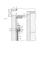
- FIG. 2 is a partial enlarged view showing an example of a cross section of a shutter mechanism in the embodiment.
- FIG. 3 is a diagram showing an example of the appearance of a shutter mechanism in the embodiment.
- FIG. 4 is a diagram illustrating an example of a pipe member according to the embodiment.
- FIG. 5 is a diagram illustrating an example of a configuration of a valve body in the embodiment.
- FIG. 6 is a diagram illustrating the flow of dry air within the cavity of the valve body in the embodiment.
- FIG. 7 is a diagram illustrating the flow of dry air within the cavity of the valve body in the embodiment.
- FIG. 8 is a diagram illustrating an example of a structure of a side wall of a chamber in the embodiment.
- a configuration can be considered in which, using conventional technology, a flow path (cavity) is formed in the circumferential direction inside the wall member of the chamber, and a cooling gas such as dry air is circulated through the flow path to cool the wall member.
- a cooling gas such as dry air
- the wall member is cooled more strongly by the cooling gas near the inlet of the flow path where the cooling gas flows in, and the further away from the inlet the temperature of the cooling gas in the flow path increases and the cooling weakens, resulting in a large temperature difference in the circumferential direction. Therefore, it is hoped that the temperature difference in the circumferential direction of the wall member can be suppressed.
- FIG. 1 is a diagram showing an example of a plasma processing apparatus in an embodiment.
- the plasma processing apparatus 1 is configured as a capacitively coupled parallel plate plasma etching apparatus.
- the plasma processing apparatus 1 includes a chamber 10.
- the chamber 10 is made of aluminum whose surface is anodized (anodized) and is formed in a cylindrical shape.
- the chamber 10 is safety grounded.
- the plasma processing apparatus 1 is not limited to a capacitively coupled parallel plate plasma etching apparatus, and may be any type of plasma processing apparatus such as an inductively coupled plasma (ICP), microwave plasma, or magnetron plasma.
- ICP inductively coupled plasma
- microwave plasma microwave plasma
- magnetron plasma magnetron plasma
- a susceptor 13 is placed inside the chamber 10.
- a cylindrical susceptor support 12 is placed at the bottom of the chamber 10 via an insulating plate 11 made of ceramic or the like.
- the susceptor 13 is placed on the susceptor support 12.
- the susceptor 13 is made of a conductive material such as aluminum, and functions as a lower electrode.
- An electrostatic chuck (ESC) 14 for holding the wafer W by electrostatic attraction is disposed on the upper surface of the susceptor 13.
- the electrostatic chuck 14 is made of an electrode plate 15 made of a conductive film and a pair of insulating layers sandwiching the electrode plate 15, e.g., dielectrics such as Y2O3 , Al2O3 , and AlN.
- the electrode plate 15 is electrically connected to a DC power supply 16 via a connection terminal.
- the electrostatic chuck 14 attracts and holds the wafer W by Coulomb force or Johnsen-Rahbek force resulting from a DC voltage applied by the DC power supply 16.
- a plurality of pusher pins are arranged as lift pins that can be freely protruded and retracted from the upper surface of the electrostatic chuck 14 at the portion of the upper surface of the electrostatic chuck 14 where the wafer W is adsorbed and held.
- These pusher pins are connected to a motor (not shown) via a ball screw (not shown).
- the pusher pins freely protrude from the upper surface of the electrostatic chuck 14 due to the rotational motion of the motor converted into linear motion by the ball screw. As a result, the pusher pins penetrate the electrostatic chuck 14 and the susceptor 13, and protrude and retract up and down in the inner space.
- the pusher pins are accommodated in the electrostatic chuck 14.
- the pusher pins protrude from the electrostatic chuck 14 and lift the wafer W upward while separating it from the electrostatic chuck 14.
- An edge ring 17 made of, for example, silicon is placed around the upper peripheral surface of the susceptor 13 to improve the uniformity of etching.
- a cover ring 54 is placed around the edge ring 17 to protect the sides of the edge ring 17.
- the sides of the susceptor 13 and susceptor support 12 are covered with a cylindrical member 18 made of, for example, quartz.
- a coolant chamber 19 extending, for example, in the circumferential direction is disposed inside the susceptor support base 12.
- a coolant for example, cooling water, at a predetermined temperature is circulated and supplied to the coolant chamber 19 from an external chiller unit (not shown) via pipes 20a and 20b.
- the coolant chamber 19 controls the processing temperature of the wafer W on the susceptor 13 by the temperature of the coolant.
- a heat transfer gas such as helium gas, is supplied from a heat transfer gas supply mechanism (not shown) through a gas supply line 21 between the upper surface of the electrostatic chuck 14 and the back surface of the wafer W.
- the heat transfer gas efficiently and uniformly controls the heat transfer between the wafer W and the susceptor 13.
- the plasma processing apparatus 1 also includes a gas inlet.
- the gas inlet is configured to introduce at least one processing gas into the chamber 10.
- the gas inlet includes a showerhead 22.
- the showerhead 22 is disposed above the susceptor 13.
- the showerhead 22 constitutes at least a part of the ceiling of the chamber 10.
- the chamber 10 has a plasma processing space 10s defined by the showerhead 22, the sidewall 10a of the chamber 10, and the susceptor 13.
- the chamber 10 is grounded.
- the showerhead 22 and the susceptor 13 are electrically insulated from the housing of the chamber 10.
- the plasma processing apparatus 1 also includes a gas supply unit 40.
- the gas supply unit 40 supplies various processing gases used in the plasma processing.
- the shower head 22 is configured to introduce at least one processing gas from the gas supply unit 40 into the plasma processing space 10s.
- the shower head 22 has at least one gas supply port 22a, at least one gas diffusion chamber 22b, and multiple gas inlets 22c.
- the processing gas supplied to the gas supply port 22a passes through the gas diffusion chamber 22b and is introduced into the plasma processing space 10s from the multiple gas inlets 22c.
- the gas inlet may include one or more side gas injectors (SGI) attached to one or more openings formed in the side wall 10a.
- SGI side gas injectors
- the gas supply 40 may include at least one gas source 41 and at least one flow controller 42.
- the gas supply 40 is configured to supply at least one process gas from a respective gas source 41 to the showerhead 22 via a respective flow controller 42.
- Each flow controller 42 may include, for example, a mass flow controller or a pressure-controlled flow controller.
- the gas supply 40 may include one or more flow modulation devices to modulate or pulse the flow rate of the at least one process gas.
- the shower head 22 includes at least one upper electrode.
- the upper high frequency power supply 31 is electrically connected to the upper electrode of the shower head 22 via the upper matcher 27.
- the upper matcher 27 is for matching the load impedance to the internal (or output) impedance of the upper high frequency power supply 31.
- the upper high frequency power supply 31 supplies high frequency power for plasma generation to the upper electrode of the shower head 22 via the upper matcher 27.
- the high frequency power for plasma generation has a frequency in the range of 10 MHz to 150 MHz.
- the upper high frequency power supply 31 may be configured to generate a plurality of high frequency powers having different frequencies.
- the upper matcher 27 functions so that the output impedance of the upper high frequency power supply 31 and the load impedance appear to match when plasma is generated in the chamber 10.
- the shower head 22 may also be provided with a refrigerant chamber or cooling jacket (not shown) to control the temperature of the electrode by a refrigerant supplied from an external chiller unit (not shown).
- An exhaust port 46 is provided at the bottom of the chamber 10.
- An automatic pressure control valve (hereinafter referred to as the "APC valve”) 48 which is a variable butterfly valve, and a turbo molecular pump (hereinafter referred to as the "TMP”) 49 are connected to the exhaust port 46.
- the APC valve 48 and the TMP 49 work together to reduce the pressure in the plasma processing space 10s in the chamber 10 to the desired vacuum level.
- an annular baffle plate 50 with multiple ventilation holes is disposed between the exhaust port 46 and the plasma processing space 10s so as to surround the susceptor 13, and the baffle plate 50 prevents leakage of plasma from the plasma processing space 10s to the exhaust port 46.
- an opening 51 for loading and unloading the wafer W is provided on the side wall 10a of the chamber 10, and a gate valve 52 for opening and closing the opening 51 is disposed therein.
- a first deposit shield 71 and a second deposit shield 72 are detachably provided along the inner wall of the chamber 10.
- the first deposit shield 71 is an upper member of the deposit shield and is provided above the opening 51 of the chamber 10.
- the second deposit shield 72 is a lower member of the deposit shield and is provided below the baffle plate 50.
- the lower portion of the first deposit shield 71 closes the opening 51 by contacting the upper portion of a valve body 81 of a shutter mechanism 80 described later.
- the first deposit shield 71 and the second deposit shield 72 can be formed, for example, by coating an aluminum material with ceramics such as Y 2 O 3 .
- the lower portion of the first deposit shield 71 is covered with a conductive material, such as stainless steel or a nickel alloy, so as to be electrically conductive with the valve body 81 that comes into contact with it.
- the wafer W is loaded and unloaded by opening and closing the gate valve 52.
- the gate valve 52 is disposed outside the chamber 10 (on the transfer chamber side)
- a space is formed in which the opening 51 protrudes toward the transfer chamber side.
- the plasma generated in the chamber 10 diffuses to the space protruding toward the transfer chamber side, causing deterioration of the plasma uniformity and deterioration of the seal material of the gate valve 52.
- the valve body 81 blocks the space between the first deposit shield 71 and the second deposit shield 72, thereby blocking the space between the opening 51 of the chamber 10 and the plasma processing space 10s.
- a lifting mechanism 82 that drives the valve body 81 is disposed, for example, below the second deposit shield 72.
- the valve body 81 is driven up and down by the lifting mechanism 82 to open and close the space between the first deposit shield 71 and the second deposit shield 72, i.e., the opening 51.
- the valve body 81 and the lifting mechanism 82 may be collectively referred to as a shutter mechanism 80.
- the first deposit shield 71, the second deposit shield 72, and the valve body 81 are examples of inner wall members of the chamber 10.
- the lower high frequency power supply 59 is electrically connected to the susceptor 13 as the lower electrode via the lower matcher 58.
- the lower high frequency power supply 59 supplies high frequency power for bias to the susceptor 13 via the lower matcher 58.
- the frequency of the high frequency power for bias may be the same as or different from that of the high frequency power for plasma generation.
- the frequency of the high frequency power for bias has a lower frequency than that of the high frequency power for plasma generation.
- the frequency of the high frequency power for bias has a frequency within the range of 100 kHz to 60 MHz.
- the lower matcher 58 is for matching the load impedance to the internal (or output) impedance of the lower high frequency power supply 59.
- the lower matcher 58 functions so that the internal impedance of the lower high frequency power supply 59 and the load impedance appear to match when plasma is generated in the plasma processing space 10s in the chamber 10.
- a second lower high frequency power supply may be connected to the lower electrode.
- a low pass filter (LPF) 61 is electrically connected to the upper electrode of the shower head 22.
- the LPF 61 is configured to pass the high frequency power from the lower high frequency power supply 59 to ground without passing the high frequency power from the upper high frequency power supply 31 to ground.
- the LPF 61 is preferably configured as an LR filter or an LC filter. However, even a single conductor can provide a sufficiently large reactance to the high frequency power from the upper high frequency power supply 31.
- the LPF 61 may be configured by simply electrically connecting a single conductor to the upper electrode of the shower head 22 instead of an LR filter or an LC filter.
- HPF high pass filter
- the plasma processing apparatus 1 may be configured to supply high frequency power for plasma generation together with high frequency power for bias to the susceptor 13 serving as the lower electrode during plasma processing.
- the plasma processing apparatus 1 may be configured to electrically connect the upper high frequency power supply 31 to the susceptor 13 via the upper matcher 27, and supply high frequency power for plasma generation from the upper high frequency power supply 31 to the susceptor 13 together with high frequency power for bias.
- the lower high frequency power supply 59 may also be configured to generate multiple high frequency powers having different frequencies. The generated one or multiple high frequency powers are supplied to the susceptor 13.
- at least one of the high frequency power for bias and the high frequency power for plasma generation may be pulsed.
- the plasma processing apparatus 1 opens the gate valve 52 and the valve body 81.
- the wafer W to be processed is carried into the chamber 10 and placed on the electrostatic chuck 14.
- the plasma processing apparatus 1 closes the gate valve 52 and the valve body 81.
- the plasma processing apparatus 1 applies a DC voltage from the DC power source 16 to the electrode plate 15 of the electrostatic chuck 14 to electrostatically attract the wafer W to the susceptor 13.
- the plasma processing apparatus 1 introduces a processing gas for etching (e.g., a mixed gas of C 4 F 8 gas and argon (Ar) gas) from the gas supply unit 40 into the plasma processing space 10s at a predetermined flow rate and flow rate ratio.
- a processing gas for etching e.g., a mixed gas of C 4 F 8 gas and argon (Ar) gas
- the plasma processing apparatus 1 also sets the pressure of the plasma processing space 10s in the chamber 10 to a value suitable for etching, for example, any value within a range of several mTorr to 1 Torr, by the APC valve 48 and the TMP 49.
- 1 Torr is equal to 133 Pa.
- the plasma processing apparatus 1 applies high-frequency power for plasma generation at a predetermined power from the upper high-frequency power supply 31 to the shower head 22, and applies high-frequency power for bias at a predetermined power from the lower high-frequency power supply 59 to the lower electrode of the susceptor 13.
- plasma is generated in the plasma processing space 10s in the plasma processing apparatus 1.
- the radicals and ions generated at this time physically or chemically etch the surface to be processed of the wafer W.
- the plasma is densified in a favorable dissociation state by applying high frequency waves in a high frequency range (a frequency range in which ions cannot move) to the shower head 22.
- high frequency waves in a high frequency range (a frequency range in which ions cannot move) to the shower head 22.
- high density plasma can be formed even under lower pressure conditions.
- FIG. 2 is a partially enlarged view showing an example of a cross section of the shutter mechanism 80 in the embodiment.
- FIG. 3 is a view showing an example of the appearance of the shutter mechanism 80 in the embodiment.
- the shutter mechanism 80 has a valve body 81 having a length of more than half of the inner circumference of the chamber 10, and two or more lifting mechanisms 82 for lifting and lowering the valve body 81.
- the valve body 81 is an annular valve body along the inner circumference of the chamber 10, for example, as shown in FIG. 3.
- the valve body 81 has a conductive member 83 that contacts the first deposit shield 71 and a conductive member 84 that contacts the second deposit shield 72 when the opening 51 is closed.
- the valve body 81 is formed, for example, from an aluminum material or the like, with a cross section that is approximately L-shaped.
- the surface of the valve body 81 is coated, for example, with Y 2 O 3 or the like.
- a conductive member 83 is disposed at the upper end of the valve body 81.
- a conductive member 84 is disposed at the step portion of the valve body 81.
- the conductive members 83 and 84 are also called conductance bands or spirals, and are conductive elastic members.
- the conductive members 83 and 84 may be made of, for example, stainless steel or nickel alloy.
- the conductive members 83 and 84 are formed, for example, by winding a band-shaped member in a spiral shape.
- the conductive members 83 and 84 may be made of, for example, a diagonally wound coil spring with a U-shaped jacket. That is, the conductive members 83 and 84 are in a state of being crushed when the valve body 81 abuts against the first deposit shield 71 and the second deposit shield 72.
- the lifting mechanism 82 has a rod.
- the rod is fixed and connected to the bottom of the valve body 81 by a screw or the like.
- the lifting mechanism 82 raises and lowers the rod up and down, for example, by an air cylinder, a motor, or the like.
- the lifting mechanism 82 is controlled so that the flow rate of dry air supplied to each lifting mechanism 82 is equal.
- three lifting mechanisms 82 are arranged at equal intervals of 120 degrees.
- Each lifting mechanism 82 raises and lowers at the same timing and speed, so that the valve body 81 can be raised and lowered without bending or tilting.
- the valve body 81 can be raised and lowered in the same way by providing lifting mechanisms 82 at both ends.
- the valve body 81 is pushed upward by the lifting mechanism 82 to close the opening 51, and is pulled downward by the lifting mechanism 82 to open the opening 51.
- the conductive members 83 and 84 arranged on the upper and lower parts of the valve body 81 abut against the first deposit shield 71 and the second deposit shield 72, respectively.
- the valve body 81 is electrically connected to the first deposit shield 71 and the second deposit shield 72 via the conductive members 83 and 84.
- the first deposit shield 71 is in contact with the chamber 10, which is grounded. Therefore, when the opening 51 is closed, the valve body 81 is grounded via the first deposit shield 71 and the second deposit shield 72.
- the valve body 81 corresponds to a part of a conventional deposit shield, and thus corresponds to a part of a conventional deposit shield divided into multiple parts.
- Conventional deposit shields are heavy and therefore difficult to work on during maintenance, but in this embodiment, because it is divided into a first deposit shield 71, a second deposit shield 72, and the valve body 81, it is easier to work on during maintenance.
- the shutter mechanism 80 is capable of controlling the temperature.
- the shutter mechanism 80 rises and falls. If an attempt is made to control the temperature of a member that rises and falls in this way by circulating a temperature-controlled liquid such as a refrigerant, the weight increases.
- a relatively large device such as a chiller unit that controls the temperature and circulates the liquid is required.
- the shutter mechanism 80 is cooled by a cooling gas.
- the shutter mechanism 80 has a cavity 90 formed inside the valve body 81 along the circumferential direction of the chamber 10.
- the cavity 90 has a rectangular cross section.
- the cavity 90 is connected around the valve body 81 in the circumferential direction and formed in a ring shape.
- the shutter mechanism 80 has at least one lifting mechanism 82 provided with a supply path and an exhaust path.
- the supply path is connected to a gas supply unit (not shown), such as a pump capable of supplying cooling gas, and the cooling gas is supplied from the gas supply unit.
- the cooling gas is, for example, dry air.
- a supply path 85 is shown in FIG. 2 in the lifting mechanism 82.
- the shutter mechanism 80 also has a heater 87 disposed inside the valve body 81.
- the heater 87 is provided on the upper surface of the cavity 90 with its lower side protruding into the cavity 90. Electricity is supplied to the heater 87 via wiring (not shown) provided in at least one of the lifting mechanisms 82.
- the temperature of the shutter mechanism 80 can be controlled by cooling it by flowing dry air into the cavity 90 and by heating it by supplying power to the heater 87.
- the dry air may be at room temperature or may be cooled.
- the shutter mechanism 80 becomes hot due to heat input from the plasma and heating by the heater 87. Therefore, even at room temperature, the dry air is relatively cold to the shutter mechanism 80, and can cool the shutter mechanism 80.
- the shutter mechanism 80 can be configured to supply dry air from the supply path to the cavity 90, circulate the air through the cavity 90, and exhaust the air from the exhaust path to cool the valve body 81.
- the valve body 81 is strongly cooled by the dry air near the entrance of the cavity 90 where the dry air flows in from the supply path 85, and the temperature of the dry air increases and the cooling weakens as the valve body 81 moves away from the entrance, resulting in a large temperature difference in the circumferential direction.
- the valve body 81 has a tube member 91 disposed within the cavity 90.
- the tube member 91 has an outer cross section formed in a rectangular shape.
- the tube member 91 is disposed within the cavity 90 along the cavity 90 of the valve body 81.
- the tube member 91 is supported by support portions 92 at multiple locations within the cavity 90.
- the tube member 91 is supported by support portions 92 provided at regular intervals (for example, every 90°), and the portions other than the support portions 92 are spaced apart from the inner surface of the cavity 90.
- the tube member 91 has a cavity 93 formed therein for flowing cooling gas.
- the cavity 93 has a rectangular cross section.
- the cavity 93 is formed in a ring shape within the tube member 91.
- the tube member 91 has a supply port 94 formed therein that communicates with the cavity 93.
- the supply port 94 is connected to the supply path 85.
- FIG. 4 is a diagram showing an example of a pipe member 91 in an embodiment.
- the pipe member 91 is connected around the circumference to form a ring.
- the pipe member 91 is made of a material with a lower thermal conductivity than the valve body 81.
- the pipe member 91 is made of a resin such as PTFE (polytetrafluoroethylene) or PEEK (polyether ether ketone).
- the pipe member 91 may also be made of stainless steel (SUS) or the like.
- the pipe member 91 has a plurality of holes 95 formed therein that communicate with the cavity 93.
- the holes 95 are formed on the upper surface of the pipe member 91 that faces the heater. Each hole 95 blows out the dry air supplied to the cavity 93.
- each hole 95 in the pipe member 91 when the size and spacing of each hole 95 in the pipe member 91 is the same, the pressure inside the cavity 93 is higher closer to the supply port 94, so the hole 95 closer to the supply port 94 blows out a greater amount of dry air, and the hole closer to the supply port 94 ends up being cooled more.
- the size of each hole 95 and/or the interval between the holes 95 of the tube member 91 are adjusted.
- the diameter of the holes 95 of the tube member 91 is increased as the tube member 91 moves away from the supply port 94 along the cavity 93.
- the holes 95 of the tube member 91 are formed at shorter intervals as the tube member 91 moves away from the supply port 94 along the cavity 93.
- the holes 95 are formed at shorter intervals as the tube member 91 moves away from the supply port 94 along the cavity 93, the amount of dry air blown out from each hole 95 of the tube member 91 can be made uniform per unit length of the tube member 91. This makes it possible to suppress the temperature difference in the circumferential direction of the valve body 81.
- a hole 95 is formed on the upper surface at a position that is ring-symmetrical to the supply port 94. This allows the pipe member 91 to blow out the dry air that has flowed through the cavity 93 from the supply port 94 through the hole 95 at the symmetrical position, thereby preventing the dry air from accumulating at a position that is ring-symmetrical to the supply port 94.
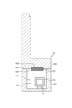
- FIG. 5 is a diagram illustrating an example of the configuration of the valve body 81 in the embodiment.
- the valve body 81 is configured by joining an upper member 100 on the upper side and a lower member 101 on the lower side.
- the upper member 100 and the lower member 101 are formed in an annular shape with the same diameter.
- the lower member 101 has a groove 103 formed in the circumferential direction on the upper surface 102 that joins with the upper member 100.
- a tube member 91 is placed in the groove 103.
- the upper member 100 has a heater 87 attached to the lower surface 105 that joins with the lower member 101.
- the upper member 100 has a groove 106 formed at a position corresponding to the groove 103.
- the groove 106 is formed in the circumferential direction on the entire circumference.
- the heater 87 is formed with a width slightly larger than the groove 106, and is attached to the upper member 100 by pressing it into the groove 106, and is integrated with the upper member 100.
- the valve body 81 is manufactured, for example, as follows: A tube member 91 is placed in the groove 103 of the lower member 101. A heater 87 is attached to the groove 106 of the upper member 100. The lower surface 105 of the upper member 100 and the upper surface 102 of the lower member 101 are then aligned so that the heater 87 of the upper member 100 is inside the groove 103 of the lower member 101, and the lower member 101 and upper member 100 are airtightly joined.
- sealing members such as O-rings are provided on the inner and outer periphery of the upper surface 102 of the lower member 101, and the upper member 100 is joined to the lower member 100 to form an airtight bond.
- the lower member 101 and upper member 100 are airtightly joined by welding.
- FIGS. 6 and 7 are diagrams illustrating the flow of dry air within the cavity 90 of the valve body 81 in the embodiment.
- FIG. 6 shows a supply path 85 and an exhaust path 86 provided in the lifting mechanism 82.
- the supply path 85 is connected to a supply port 94 of the pipe member 91.
- the exhaust path 86 is connected to the cavity 90.
- the exhaust path 86 is connected to an exhaust section provided outside the chamber 10.
- the exhaust section may be, for example, the APC valve 48 and the TMP 49, or may be a different exhaust device.
- Dry air supplied from the supply path 85 is supplied to the supply port 94 of the tube member 91.
- the dry air supplied to the supply port 94 flows through the cavity 93 of the tube member 91 and is blown out from the hole 95 into the cavity 90. Because the holes 95 are formed at multiple positions in the circumferential direction of the tube member 91, the dry air is blown out into the cavity 90 from multiple positions in the circumferential direction. This allows the valve body 81 to be cooled at multiple positions in the circumferential direction, thereby suppressing the temperature difference around the valve body 81. This allows the temperature uniformity around the valve body 81 to be improved.
- the dry air blown out from the hole 95 flows inside the cavity 90 around the tube member 91 and is exhausted from the exhaust path 86 to the outside of the chamber 10.
- the shutter mechanism 80 blows out the dry air supplied from the supply path 85 from multiple positions around the circumference of the tube member 91 and exhausts the blown out dry air from the exhaust path, thereby circulating the dry air and cooling the valve body 81.
- valve body 81 of the shutter mechanism 80 an example of cooling the valve body 81 of the shutter mechanism 80 has been described.
- the structure of the valve body 81 in the embodiment may be applied to the inner wall member of the chamber 10 to cool the inner wall member.
- a cavity may be formed in the circumferential direction in a deposit shield such as the first deposit shield 71 or the second deposit shield 72, similar to the valve body 81, and a tube member may be placed in the cavity to cool the deposit shield.
- the structure of the valve body 81 in the embodiment may be applied to the outer wall member of the chamber 10 to cool the outer wall member.
- the structure of the valve body 81 in the embodiment may be applied to the side wall 10a of the chamber 10 as the outer wall member to cool the side wall 10a.
- FIG. 8 is a diagram showing an example of the structure of the side wall 10a of the chamber 10 in the embodiment.
- the side wall 10a has a cavity 110 formed therein.
- the cavity 110 has a rectangular cross section.
- the cavity 110 is connected around the circumference of the chamber 10 to form a ring shape.
- the side wall 10a also has a heater 111 disposed inside.
- the heater 111 is disposed above the cavity 110.
- the side wall 10a has a tube member 112 disposed within the cavity 110.
- the tube member 112 is disposed within the cavity 110 along the cavity 110 of the side wall 10a.
- the pipe member 112 is supported by the support parts 114 at multiple locations in the cavity 110.
- the pipe member 112 is configured in the same manner as the pipe member 91, and a cavity 113 for flowing cooling gas is formed inside, and holes communicating with the cavity 113 are formed at multiple locations in the circumferential direction.
- Dry air is supplied to the pipe member 112 from a supply path (not shown).
- the supplied dry air flows through the cavity 113 of the pipe member 112 and is blown out from the hole into the cavity 110.
- the dry air blown out from the hole flows inside the cavity 110 and is exhausted from an exhaust path (not shown) communicating with the cavity 110.
- the side wall 10a supplies dry air from the supply path to the pipe member 112 and blows dry air into the cavity 110 from multiple locations in the circumferential direction of the pipe member 112, thereby cooling the side wall 10a from multiple locations in the circumferential direction and suppressing the temperature difference in the circumferential direction of the side wall 10a.
- the valve body 81 is cooled by flowing dry air into the cavity 90, and the valve body 81 is heated by supplying power to the heater 87, thereby controlling the temperature of the valve body 81.
- this is not limited to this. If the valve body 81 is sufficiently heated by the heat input from the plasma, the heater 87 does not need to be provided.
- the tube members 91 are arranged in a ring shape around the entire circumference of the cavity 90.
- the tube members 91 may be arranged discretely around the entire circumference of the cavity 90.
- multiple arc-shaped tube members 91 may be individually arranged in a circumferential range in the cavity 90 of the valve body 81, and cooling gas may be supplied to each tube member 91 from a supply path provided in each of the multiple lifting mechanisms 82.
- the exhaust path may be provided in any one of the lifting mechanisms 82, or in each of the multiple lifting mechanisms 82.
- the cross-sectional shape of the cavity 90 and the cavity 110 is rectangular. However, this is not limited to this.
- the cross-sectional shape of the cavity 90 and the cavity 110 may be any shape.
- the cross-sectional shape of the cavity 90 and the cavity 110 may be circular, elliptical, or polygonal.
- the cross-sectional shape of the pipe members 91 and 112 is rectangular. However, this is not limited to this.
- the cross-sectional shape of the pipe members 91 and 112 may be any shape. It is preferable that the cross-sectional shape of the pipe members 91 and 112 be the same as that of the cavities 90 and 110, so that when the pipe members 91 and 112 are placed in the cavities 90 and 110, gaps are provided around them to facilitate the flow of gas.
- the cross-sectional shape of the cavity 93 and the cavity 113 is rectangular. However, this is not limited to this.
- the cross-sectional shape of the cavity 93 and the cavity 113 may be any shape. Since the cavity 93 and the cavity 113 are formed in the tube member 91 and the tube member 112, it is preferable that they have a cross-sectional shape similar to the outer shape of the tube member 91 and the tube member 112.
- the wall member in the embodiment has a wall member body (e.g., valve body 81, side wall 10a) and a tube member (e.g., tube member 91, tube member 112).
- the wall member body is provided in the circumferential direction of the processing vessel (chamber 10) and is configured to form a first cavity (e.g., cavity 90, cavity 110) along the circumferential direction inside.
- the tube member is disposed in the first cavity and is formed of a material having a lower thermal conductivity than the wall member body, and is configured to form a second cavity (e.g., cavity 93, cavity 113) for flowing cooling gas therein and to have at least one hole (e.g., hole 95) configured to communicate the first cavity with the second cavity. This makes it possible to suppress the temperature difference in the circumferential direction of the wall member.
- the wall member body is an inner wall member of the processing vessel (e.g., valve body 81, deposit shield). This makes it possible to suppress the temperature difference in the circumferential direction of the inner wall member of the processing vessel.
- the wall member body is the outer wall member of the processing vessel (e.g., side wall 10a). This makes it possible to suppress the temperature difference in the circumferential direction of the outer wall member of the processing vessel.
- the wall member main body e.g., valve body 81
- a lifting mechanism e.g., lifting mechanism 82
- the wall member main body is supported by a lifting mechanism (e.g., lifting mechanism 82) that can be raised and lowered, and is configured so that cooling gas is supplied to the second cavity (e.g., cavity 93) from a supply path (e.g., supply path 85) provided in the lifting mechanism, and cooling gas in the first cavity (e.g., cavity 90) is exhausted to an exhaust path (e.g., exhaust path 86) provided in the lifting mechanism.
- a supply path e.g., supply path 85
- an exhaust path e.g., exhaust path 86
- the wall member body is made of aluminum.
- the tube member is made of resin. This allows the wall member body to have high thermal conductivity. Also, by making the tube member out of resin, it is possible to reduce heat transfer to the cooling gas flowing in the second cavity.
- the wall member body is formed in a ring shape along the circumferential direction
- the first cavity is formed in a ring shape along the circumferential direction inside.
- the tube members are configured to be arranged in a ring shape around the entire circumference of the first cavity, or are configured to be arranged discretely around the entire circumference of the first cavity. This makes it possible to suppress the temperature difference around the wall member.
- the tube members e.g., tube members 91 and 112 are formed so that their cross sections are smaller than the cross sections of the first cavity (e.g., cavity 90 and 110), and are supported at multiple points on their undersides by support portions (e.g., support portions 92 and 114), and are configured to be positioned apart from the underside of the first cavity at points other than the support portions. This makes it possible to suppress heat transfer to the tube members.
- the tube member is configured so that the diameter of the hole increases the further away along the second cavity from the supply port (e.g., supply port 94) through which the cooling gas is supplied. This makes it possible to further suppress the temperature difference in the circumferential direction of the wall member.
- the pipe member is also configured so that the holes are spaced closer together along the second cavity as they move away from the supply port (e.g., supply port 94) through which the cooling gas is supplied. This makes it possible to further suppress the temperature difference in the circumferential direction of the wall member.
- the cooling gas is dry air. This allows cooling while suppressing the occurrence of condensation in the first and second cavities.
- the wall member body also has a heater (heater 87) provided inside along the circumferential direction.
- the tube member is configured so that a hole is formed on the heater side. This allows the heater side of the valve body 81 to be strongly cooled.
- the plasma processing apparatus performs etching as the plasma processing.
- the plasma processing may be any processing such as a film formation process or an ashing process.
- a wall member body provided in a circumferential direction of the processing vessel and configured to define a first cavity therein along the circumferential direction;
- a pipe member that is disposed in the first cavity, is made of a material having a lower thermal conductivity than the wall member body, has a second cavity formed therein for flowing a cooling gas, and is configured to have at least one hole formed therein that is configured to communicate the first cavity with the second cavity;
- Appendix 4 The wall member described in any one of Appendices 1 to 3, wherein the wall member main body is configured to be supported by a lifting mechanism that can be raised and lowered, and a cooling gas is supplied to the second cavity from a supply path provided in the lifting mechanism, and the cooling gas in the first cavity is exhausted to an exhaust path provided in the lifting mechanism.
- the wall member body is formed in a ring shape along the circumferential direction
- the first cavity is formed in a ring shape along the circumferential direction inside the wall member body
- Appendix 8 The wall member of any one of appendices 1 to 8, wherein the pipe member is supported by support portions at multiple points on the underside and is configured to be positioned apart from the underside of the first cavity at portions other than the support portions.
- Appendix 10 The wall member according to any one of appendices 1 to 9, wherein the pipe member is configured such that the holes are formed at shorter intervals as the pipe member moves away from a supply port through which a cooling gas is supplied along the second cavity.
- the wall member body has a heater provided therein along the circumferential direction, The wall member according to any one of appendices 1 to 11, wherein the pipe member is configured so that the hole is formed on the heater side.
- REFERENCE SIGNS LIST 1 plasma processing apparatus 10 chamber 10a side wall 10s plasma processing space 71 first deposit shield 72 second deposit shield 80 shutter mechanism 81 valve body 82 lift mechanism 83 conductive member 84 conductive member 85 supply path 86 exhaust path 87 heater 90 cavity 91 tube member 92 support portion 93 cavity 94 supply port 100 upper member 101 lower member 102 upper surface 110 cavity 111 heater 112 tube member 113 cavity 114 support portion W wafer
Landscapes
- Physics & Mathematics (AREA)
- Engineering & Computer Science (AREA)
- Plasma & Fusion (AREA)
- Chemical & Material Sciences (AREA)
- Analytical Chemistry (AREA)
- Electromagnetism (AREA)
- Spectroscopy & Molecular Physics (AREA)
- Plasma Technology (AREA)
- Chemical Vapour Deposition (AREA)
- Physical Or Chemical Processes And Apparatus (AREA)
Priority Applications (4)
| Application Number | Priority Date | Filing Date | Title |
|---|---|---|---|
| KR1020257026941A KR20250153776A (ko) | 2023-02-21 | 2024-02-16 | 벽부재 및 플라즈마 처리 장치 |
| JP2025502338A JP7770611B2 (ja) | 2023-02-21 | 2024-02-16 | 壁部材およびプラズマ処理装置 |
| CN202480012463.1A CN120693683A (zh) | 2023-02-21 | 2024-02-16 | 壁部件和等离子体处理装置 |
| US19/298,235 US20250364232A1 (en) | 2023-02-21 | 2025-08-13 | Wall member and plasma processing apparatus |
Applications Claiming Priority (2)
| Application Number | Priority Date | Filing Date | Title |
|---|---|---|---|
| JP2023-024921 | 2023-02-21 | ||
| JP2023024921 | 2023-02-21 |
Related Child Applications (1)
| Application Number | Title | Priority Date | Filing Date |
|---|---|---|---|
| US19/298,235 Continuation US20250364232A1 (en) | 2023-02-21 | 2025-08-13 | Wall member and plasma processing apparatus |
Publications (1)
| Publication Number | Publication Date |
|---|---|
| WO2024176976A1 true WO2024176976A1 (ja) | 2024-08-29 |
Family
ID=92501208
Family Applications (1)
| Application Number | Title | Priority Date | Filing Date |
|---|---|---|---|
| PCT/JP2024/005562 Ceased WO2024176976A1 (ja) | 2023-02-21 | 2024-02-16 | 壁部材およびプラズマ処理装置 |
Country Status (6)
| Country | Link |
|---|---|
| US (1) | US20250364232A1 (https=) |
| JP (1) | JP7770611B2 (https=) |
| KR (1) | KR20250153776A (https=) |
| CN (1) | CN120693683A (https=) |
| TW (1) | TW202507794A (https=) |
| WO (1) | WO2024176976A1 (https=) |
Citations (5)
| Publication number | Priority date | Publication date | Assignee | Title |
|---|---|---|---|---|
| JP2006093411A (ja) * | 2004-09-24 | 2006-04-06 | Hitachi Kokusai Electric Inc | 基板処理装置 |
| JP2010258404A (ja) * | 2009-03-31 | 2010-11-11 | Tokyo Electron Ltd | 半導体製造装置及び温調方法 |
| JP2019197849A (ja) * | 2018-05-11 | 2019-11-14 | 東京エレクトロン株式会社 | プラズマ処理装置 |
| JP2021002642A (ja) * | 2019-06-18 | 2021-01-07 | 東京エレクトロン株式会社 | 基板処理装置 |
| JP2022070597A (ja) * | 2020-10-27 | 2022-05-13 | 東京エレクトロン株式会社 | プラズマ処理装置 |
Family Cites Families (1)
| Publication number | Priority date | Publication date | Assignee | Title |
|---|---|---|---|---|
| JP5396256B2 (ja) | 2009-12-10 | 2014-01-22 | 東京エレクトロン株式会社 | プラズマ処理装置 |
-
2024
- 2024-02-15 TW TW113105292A patent/TW202507794A/zh unknown
- 2024-02-16 KR KR1020257026941A patent/KR20250153776A/ko active Pending
- 2024-02-16 JP JP2025502338A patent/JP7770611B2/ja active Active
- 2024-02-16 CN CN202480012463.1A patent/CN120693683A/zh active Pending
- 2024-02-16 WO PCT/JP2024/005562 patent/WO2024176976A1/ja not_active Ceased
-
2025
- 2025-08-13 US US19/298,235 patent/US20250364232A1/en active Pending
Patent Citations (5)
| Publication number | Priority date | Publication date | Assignee | Title |
|---|---|---|---|---|
| JP2006093411A (ja) * | 2004-09-24 | 2006-04-06 | Hitachi Kokusai Electric Inc | 基板処理装置 |
| JP2010258404A (ja) * | 2009-03-31 | 2010-11-11 | Tokyo Electron Ltd | 半導体製造装置及び温調方法 |
| JP2019197849A (ja) * | 2018-05-11 | 2019-11-14 | 東京エレクトロン株式会社 | プラズマ処理装置 |
| JP2021002642A (ja) * | 2019-06-18 | 2021-01-07 | 東京エレクトロン株式会社 | 基板処理装置 |
| JP2022070597A (ja) * | 2020-10-27 | 2022-05-13 | 東京エレクトロン株式会社 | プラズマ処理装置 |
Also Published As
| Publication number | Publication date |
|---|---|
| CN120693683A (zh) | 2025-09-23 |
| JPWO2024176976A1 (https=) | 2024-08-29 |
| TW202507794A (zh) | 2025-02-16 |
| US20250364232A1 (en) | 2025-11-27 |
| KR20250153776A (ko) | 2025-10-27 |
| JP7770611B2 (ja) | 2025-11-14 |
Similar Documents
| Publication | Publication Date | Title |
|---|---|---|
| CN111524850B (zh) | 载置台和基片处理装置 | |
| US11862436B2 (en) | Plasma processing apparatus and plasma processing method | |
| JP4997842B2 (ja) | 処理装置 | |
| US5683537A (en) | Plasma processing apparatus | |
| US20150187542A1 (en) | Substrate processing apparatus, shutter device and plasma processing apparatus | |
| JP6199638B2 (ja) | プラズマ処理装置 | |
| TWI902937B (zh) | 電漿處理裝置 | |
| TW201936014A (zh) | 電漿處理裝置 | |
| JP2004342703A (ja) | プラズマ処理装置及びプラズマ処理方法 | |
| JP7686038B2 (ja) | 基板処理装置 | |
| JP4583618B2 (ja) | プラズマ処理装置 | |
| WO2007148690A1 (ja) | マイクロ波導入装置及びプラズマ処理装置 | |
| KR20240077235A (ko) | 냉각 플레이트 및 이를 포함하는 플라즈마 처리 챔버 | |
| JP7770611B2 (ja) | 壁部材およびプラズマ処理装置 | |
| CN100477091C (zh) | 处理装置 | |
| KR102212998B1 (ko) | 기판 처리 장치 | |
| JP4436098B2 (ja) | 半導体製造装置 | |
| WO2026028899A1 (ja) | 基板保持機構、基板処理装置及び制御方法 | |
| JP2026007621A (ja) | 基板処理装置、および基板処理方法 | |
| WO2026042745A1 (ja) | 半導体製造装置、および温度調整方法 | |
| TW202607818A (zh) | 基板處理裝置及擋門機構 |
Legal Events
| Date | Code | Title | Description |
|---|---|---|---|
| 121 | Ep: the epo has been informed by wipo that ep was designated in this application |
Ref document number: 24760275 Country of ref document: EP Kind code of ref document: A1 |
|
| WWE | Wipo information: entry into national phase |
Ref document number: 2025502338 Country of ref document: JP |
|
| ENP | Entry into the national phase |
Ref document number: 1020257026941 Country of ref document: KR Free format text: ST27 STATUS EVENT CODE: A-0-1-A10-A15-NAP-PA0105 (AS PROVIDED BY THE NATIONAL OFFICE) |
|
| WWE | Wipo information: entry into national phase |
Ref document number: 202480012463.1 Country of ref document: CN |
|
| NENP | Non-entry into the national phase |
Ref country code: DE |
|
| WWP | Wipo information: published in national office |
Ref document number: 202480012463.1 Country of ref document: CN |
|
| WWP | Wipo information: published in national office |
Ref document number: 1020257026941 Country of ref document: KR |
|
| 122 | Ep: pct application non-entry in european phase |
Ref document number: 24760275 Country of ref document: EP Kind code of ref document: A1 |