WO2024176809A1 - 電線固定部材およびワイヤハーネス - Google Patents
電線固定部材およびワイヤハーネス Download PDFInfo
- Publication number
- WO2024176809A1 WO2024176809A1 PCT/JP2024/003846 JP2024003846W WO2024176809A1 WO 2024176809 A1 WO2024176809 A1 WO 2024176809A1 JP 2024003846 W JP2024003846 W JP 2024003846W WO 2024176809 A1 WO2024176809 A1 WO 2024176809A1
- Authority
- WO
- WIPO (PCT)
- Prior art keywords
- fixing member
- electric wire
- locking portion
- fixed
- clamping member
- Prior art date
- Legal status (The legal status is an assumption and is not a legal conclusion. Google has not performed a legal analysis and makes no representation as to the accuracy of the status listed.)
- Ceased
Links
Images


Classifications
-
- H—ELECTRICITY
- H02—GENERATION; CONVERSION OR DISTRIBUTION OF ELECTRIC POWER
- H02G—INSTALLATION OF ELECTRIC CABLES OR LINES, OR OF COMBINED OPTICAL AND ELECTRIC CABLES OR LINES
- H02G3/00—Installations of electric cables or lines or protective tubing therefor in or on buildings, equivalent structures or vehicles
- H02G3/30—Installations of cables or lines on walls, floors or ceilings
- H02G3/32—Installations of cables or lines on walls, floors or ceilings using mounting clamps
-
- B—PERFORMING OPERATIONS; TRANSPORTING
- B60—VEHICLES IN GENERAL
- B60R—VEHICLES, VEHICLE FITTINGS, OR VEHICLE PARTS, NOT OTHERWISE PROVIDED FOR
- B60R16/00—Electric or fluid circuits specially adapted for vehicles and not otherwise provided for; Arrangement of elements of electric or fluid circuits specially adapted for vehicles and not otherwise provided for
- B60R16/02—Electric or fluid circuits specially adapted for vehicles and not otherwise provided for; Arrangement of elements of electric or fluid circuits specially adapted for vehicles and not otherwise provided for electric constitutive elements
- B60R16/0207—Wire harnesses
- B60R16/0215—Protecting, fastening and routing means therefor
-
- F—MECHANICAL ENGINEERING; LIGHTING; HEATING; WEAPONS; BLASTING
- F16—ENGINEERING ELEMENTS AND UNITS; GENERAL MEASURES FOR PRODUCING AND MAINTAINING EFFECTIVE FUNCTIONING OF MACHINES OR INSTALLATIONS; THERMAL INSULATION IN GENERAL
- F16B—DEVICES FOR FASTENING OR SECURING CONSTRUCTIONAL ELEMENTS OR MACHINE PARTS TOGETHER, e.g. NAILS, BOLTS, CIRCLIPS, CLAMPS, CLIPS OR WEDGES; JOINTS OR JOINTING
- F16B2/00—Friction-grip releasable fastenings
- F16B2/02—Clamps, i.e. with gripping action effected by positive means other than the inherent resistance to deformation of the material of the fastening
- F16B2/06—Clamps, i.e. with gripping action effected by positive means other than the inherent resistance to deformation of the material of the fastening external, i.e. with contracting action
- F16B2/10—Clamps, i.e. with gripping action effected by positive means other than the inherent resistance to deformation of the material of the fastening external, i.e. with contracting action using pivoting jaws
-
- H—ELECTRICITY
- H01—ELECTRIC ELEMENTS
- H01B—CABLES; CONDUCTORS; INSULATORS; SELECTION OF MATERIALS FOR THEIR CONDUCTIVE, INSULATING OR DIELECTRIC PROPERTIES
- H01B7/00—Insulated conductors or cables characterised by their form
-
- H—ELECTRICITY
- H02—GENERATION; CONVERSION OR DISTRIBUTION OF ELECTRIC POWER
- H02G—INSTALLATION OF ELECTRIC CABLES OR LINES, OR OF COMBINED OPTICAL AND ELECTRIC CABLES OR LINES
- H02G3/00—Installations of electric cables or lines or protective tubing therefor in or on buildings, equivalent structures or vehicles
- H02G3/30—Installations of cables or lines on walls, floors or ceilings
Definitions
- This disclosure relates to an electric wire fixing member and a wire harness.
- Patent Document 1 describes an electric wire fixing member that is fixed to a plate-shaped bracket provided on a vehicle.
- the electric wire fixing member includes a holding portion that holds the electric wire member, and a fixing portion that is fixed to the plate-shaped bracket.
- the fixing portion has an insertion hole into which the bracket is inserted. Inside the insertion hole, a locking portion is provided that hooks onto the bracket to prevent the bracket from slipping out of the insertion hole.
- the thickness of the bracket in a vehicle is set to various thicknesses depending on the weight of the electric wire member, etc., from the perspective of ensuring strength.
- the size of the insertion hole, etc. must be designed to match the plate thickness of the bracket. For example, consider a case where an electric wire fixing member suitable for a first bracket is fixed to a second bracket that is thinner than the first bracket. In this case, a large gap occurs between the insertion hole of the electric wire fixing member and the second bracket, which may cause rattling or even the electric wire fixing member to fall off. Therefore, it was necessary to prepare a variety of electric wire fixing members according to the plate thickness of the bracket.
- the purpose of this disclosure is to provide a wire fixing member and a wire harness that enable improved versatility.
- the electric wire fixing member of the present disclosure is an electric wire fixing member for fixing an electric wire member to a plate-shaped fixed part, and includes a fixing member main body having a holding part for holding the electric wire member and an arrangement surface on which the fixed part is arranged, and a clamping member that is separate from the fixing member main body and is assembled to the fixing member main body, and the arrangement surface and the clamping member are configured to be able to clamp the fixed part between them.
- the electric wire fixing member and wire harness disclosed herein can improve versatility.
- FIG. 1 is a front view showing a wire harness according to an embodiment.
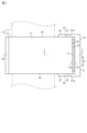
- FIG. 2 is a plan view of the wire harness of the same embodiment.
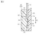
- FIG. 3 is a cross-sectional view taken along line 3-3 in FIG.
- FIG. 4 is a cross-sectional view showing a part of a wire fixing member in a modified example.
- the electric wire fixing member of the present disclosure includes: [1] An electric wire fixing member for fixing an electric wire member to a plate-shaped fixed portion, comprising: a fixing member main body having a holding portion for holding the electric wire member and an arrangement surface on which the fixed portion is arranged; and a clamping member that is separate from the fixing member main body and is assembled to the fixing member main body, wherein the arrangement surface and the clamping member are configured to be able to clamp the fixed portion between them.
- the fixing member body has a first locking portion
- the clamping member has a second locking portion that hooks onto the first locking portion
- the fixing member body and the clamping member are fixed to each other by the first locking portion and the second locking portion hooking onto each other
- the first locking portion and the second locking portion may be configured to be capable of fixing the clamping member at a plurality of fixing positions having different distances from the placement surface.
- the distance between the arrangement surface of the fixing member main body and the clamping member can be changed by changing the configuration of the first locking portion and the second locking portion.
- a plurality of combinations of the first locking portion and the second locking portion hooked onto the first locking portion may be provided.
- either the placement surface or the clamping member may have a protrusion that is inserted into a hole provided in the fixed portion.
- a wire harness according to the present disclosure includes the wire fixing member according to any one of [1] to [4] above, and a wire member held by the wire fixing member.
- the wire harness 10 of this embodiment is installed in a vehicle such as an automobile.
- the wire harness 10 includes an electric wire member 11 and an electric wire fixing member 12.
- the electric wire fixing member 12 is a component for fixing to a plate-shaped fixed part 13 installed in the vehicle.
- the fixed part 13 is, for example, a metal plate-shaped bracket.
- the electric wire member 11 electrically connects two or more on-board devices.
- the electric wire member 11 includes, for example, an electric wire and an exterior member that covers the outer circumference of the electric wire.
- the plate-shaped fixed portion 13 has a first main surface 13x and a second main surface 13y that are parallel to each other. As shown in FIG. 3, the fixed portion 13 has, for example, a hole 14.
- the hole 14 is, for example, a through hole that penetrates the fixed portion 13 from the first main surface 13x to the second main surface 13y.
- the electric wire fixing member 12 includes a fixing member body 20 and a clamping member 30 that is separate from the fixing member body 20.
- the fixing member body 20 and the clamping member 30 are each formed of, for example, a synthetic resin.
- the fixing member body 20 and the clamping member 30 clamp the fixed portion 13 in the plate thickness direction.
- the fixing member body 20 has a holding portion 21 that holds the electric wire member 11 and an attachment portion 22 to which the clamping member 30 is attached.
- the holding portion 21 is annular when viewed in the longitudinal direction of the electric wire member 11.
- the holding portion 21 surrounds the outer periphery of the electric wire member 11. This allows the electric wire member 11 to be held by the holding portion 21.
- the holding portion 21 has, for example, a protruding portion 23 protruding from an inner circumferential surface of the holding portion 21.
- the protruding portion 23 is configured to hook onto the electric wire member 11 in the longitudinal direction.
- the protruding portion 23 By the protruding portion 23 being hooked onto the electric wire member 11 in the longitudinal direction, a relative positional deviation between the electric wire member 11 and the electric wire fixing member 12 in the longitudinal direction is suppressed. Note that, when the exterior member of the electric wire member 11 is, for example, a corrugated tube, the protruding portion 23 fits into a recess in the outer circumferential surface of the corrugated tube.
- the attachment portion 22 has an arrangement surface 24 on which the fixed portion 13 is arranged, and a plurality of first locking portions 25.
- the arrangement surface 24 is, for example, a flat surface parallel to the fixed portion 13.
- the placement surface 24 has, for example, a protrusion 26 that is inserted into the hole 14 of the fixed portion 13.
- the protrusion 26 fits into the hole 14, positioning the fixed portion 13 in a direction parallel to the placement surface 24.
- the fixed portion 13 is positioned in the width direction D1 and height direction D2 by the protrusion 26.
- the first locking portions 25 are, for example, locking projections that protrude from both side surfaces 22a of the mounting portion 22 in the width direction D1.
- a pair of first locking portions 25 provided on both side surfaces 22a of the mounting portion 22 are provided in a plurality of sets so as to be aligned in the height direction D2 of the mounting portion 22 (see FIG. 1).
- the pair of first locking portions 25 is provided in the vicinity of one end and the other end of the mounting portion 22 in the height direction D2. That is, the mounting portion 22 of this embodiment is provided with four first locking portions 25.
- Each first locking portion 25 is adapted to hook onto a fixing piece 32 of the clamping member 30, which will be described later.
- the height direction D2 of the mounting portion 22 is parallel to the arrangement surface 24 and perpendicular to the width direction D1.
- the fixed portion 13 is arranged along the height direction D2 so as to be in contact with the arrangement surface 24.
- the fixing member main body 20 has a structure divided into two parts, a first part 41 and a second part 42, for example, from the holding part 21 to the mounting part 22.
- the first part 41 and the second part 42 are connected to each other via a hinge part 43.
- the first part 41, the second part 42 and the hinge part 43 are integrally formed.
- the second part 42 can rotate with respect to the first part 41, with the hinge part 43 as an axis.
- the hinge part 43 is provided, for example, on the holding part 21.
- the mounting portion 22 of the fixing member main body 20 is formed, for example, by a part of the first portion 41 and a part of the second portion 42.
- the first portion 41 and the second portion 42 are held closed by connecting the connecting portions (not shown) provided on each of the first portion 41 and the second portion 42 in the mounting portion 22.
- the placement surface 24 of the mounting portion 22 is formed, for example, by a part of the first portion 41 and a part of the second portion 42.
- the first locking portion 25 is provided, for example, on each of the first portion 41 and the second portion 42 in the mounting portion 22.
- the clamping member 30 has, for example, a main body portion 31 and a plurality of fixing pieces 32 extending from the main body portion 31.
- Each fixing piece 32 extends from the main body portion 31 in a direction perpendicular to the arrangement surface 24.
- Each fixing piece 32 has a second locking portion 33 that is hooked onto each first locking portion 25 of the mounting portion 22.
- the second locking portion 33 in each fixing piece 32 is, for example, a through hole that penetrates the fixing piece 32 in the width direction D1.
- each first locking portion 25 enters and gets hooked onto the second locking portion 33 of each fixing piece 32, so that the clamping member 30 is fixed to the mounting portion 22 in a state in which the fixed portion 13 is sandwiched between the arrangement surface 24 and the main body portion 31 in the plate thickness direction.
- the arrangement surface 24 contacts a first main surface 13x of the fixed portion 13
- the main body portion 31 contacts a second main surface 13y of the fixed portion 13 .
- the first locking portion 25 of the attachment portion 22 and the second locking portion 33 of the clamping member 30 are configured to be able to fix the clamping member 30 at a plurality of fixing positions having different distances from the placement surface 24 . More specifically, in each fixed piece 32, a plurality of second locking portions 33 are provided along a direction perpendicular to the arrangement surface 24. The number of second locking portions 33 is the same for each fixed piece 32. The distance between the second locking portions 33 in the direction perpendicular to the arrangement surface 24 is also the same for each fixed piece 32. Note that, although the drawings show three second locking portions 33 in each fixed piece 32, the number of second locking portions 33 in each fixed piece 32 is not limited to three, and may be two or four or more.
- the first locking portion 25 is adapted to hook onto one of the second locking portions 33 in the fixed piece 32.
- the distance between the main body portion 31 of the clamping member 30 and the placement surface 24 of the mounting portion 22 changes depending on which second locking portion 33 in the fixed piece 32 the first locking portion 25 is hooked onto.
- the clamping member 30 has, for example, a covering portion 34.
- the covering portion 34 is formed on the clamping member 30, for example, between the fixing pieces 32 in the height direction D2.
- the covering portion 34 extends from both ends of the main body portion 31 in the width direction D1.
- Each covering portion 34 faces the side surface 22a of the mounting portion 22 in the width direction D1.
- the covering portion 34 is configured to cover the gap between the placement surface 24 and the main body portion 31 in the width direction D1. As a result, the covering portion 34 prevents the fixed portion 13 from being exposed from the gap between the placement surface 24 and the main body portion 31 when viewed from the width direction D1.
- the clamping member 30 is attached to the mounting portion 22 by hooking the second locking portion 33 of the clamping member 30 to the first locking portion 25 of the mounting portion 22 of the fixing member main body 20.
- the fixed portion 13 is clamped in the plate thickness direction by the arrangement surface 24 of the mounting portion 22 and the main body portion 31 of the clamping member 30.
- the distance between the arrangement surface 24 of the mounting portion 22 and the main body portion 31 of the clamping member 30 can be adjusted depending on which second locking portion 33 of the fixing piece 32 the first locking portion 25 is hooked to.
- the electric wire fixing member 12 includes a fixing member main body 20 and a clamping member 30 assembled to the fixing member main body 20.
- the arrangement surface 24 of the fixing member main body 20 and the clamping member 30 are configured to be able to clamp the fixed portion 13 therebetween. According to this configuration, by changing the distance between the arrangement surface 24 of the fixing member main body 20 and the clamping member 30, it is possible to clamp various fixed portions 13 having different plate thicknesses while suppressing rattling. In other words, by changing the distance between the arrangement surface 24 and the clamping member 30 according to the plate thickness of the fixed portion 13, it is possible to accommodate various fixed portions 13 having different plate thicknesses. Therefore, it is possible to improve the versatility of the electric wire fixing member 12.
- the fixing member body 20 has a first locking portion 25.
- the clamping member 30 has a second locking portion 33 that hooks onto the first locking portion 25.
- the fixing member body 20 and the clamping member 30 are fixed to each other by the first locking portion 25 hooking onto the second locking portion 33.
- the first locking portion 25 and the second locking portion 33 are configured so that the clamping member 30 can be fixed at a plurality of fixing positions with different distances from the placement surface 24. With this configuration, it is possible to change the distance between the placement surface 24 of the fixing member body 20 and the clamping member 30 depending on the configuration of the first locking portion 25 and the second locking portion 33.
- the placement surface 24 has a protrusion 26 that is inserted into a hole 14 provided in the fixed portion 13.
- the protrusion 26 inserted into the hole 14 of the fixed portion 13 makes it possible to prevent the fixed portion 13 from slipping out from between the placement surface 24 and the clamping member 30.
- the configuration of the first locking portion 25 of the fixing member main body 20 and the second locking portion 33 of the clamping member 30 is not limited to the above embodiment.
- the first locking portion 25 and the second locking portion 33 need only be configured to be able to fix the clamping member 30 at a plurality of fixing positions with different distances from the placement surface 24.
- the configuration of the first locking portion 25 and the second locking portion 33 can be changed, for example, as shown in FIG. 4.
- the mounting portion 22 of the fixing member main body 20 has a first locking portion 51 having a plurality of projections and recesses.
- the first locking portion 51 is provided, for example, on at least a portion of the inner circumferential surface of a cylindrical portion 52 formed on the side surface 22a of the mounting portion 22 in the width direction D1.
- a plurality of projections and recesses are alternately arranged along a direction perpendicular to the placement surface 24.
- the fixed piece 32 of the clamping member 30 has a second locking portion 53 with multiple concave and convex shapes.
- the second locking portion 53 multiple concave and convex shapes are arranged alternately along a direction perpendicular to the placement surface 24.
- the concave and convex shapes of the second locking portion 53 are formed in the same manner as the concave and convex shapes of the first locking portion 51.
- the first and second locking portions 51 and 53 have a configuration in which multiple projections and recesses are arranged alternately in a direction perpendicular to the placement surface 24. This allows the first and second locking portions 51 and 53 to fix the clamping member 30 at multiple fixing positions with different distances from the placement surface 24. Even with this configuration, it is possible to change the distance between the placement surface 24 and the clamping member 30 depending on the configuration of the first and second locking portions 51 and 53.
- the protrusion 26 to be inserted into the hole 14 of the fixed part 13 is provided on the arrangement surface 24, but this is not limited thereto, and the protrusion to be inserted into the hole 14 of the fixed part 13 may be provided on the main body part 31 of the clamping member 30.
- the hole 14 of the fixed part 13 may be a recess formed in the first main surface 13x. In other words, the hole 14 of the fixed part 13 may not extend from the first main surface 13x to the second main surface 13y of the fixed part 13.
- the clamping member 30 is fixed to the fixing member body 20 by the hooking of the first locking portion 25 of the fixing member body 20 and the second locking portion 33 of the clamping member 30, but this is not particularly limited.
- the electric wire fixing member 12 may be configured to include a connecting member separate from each of the fixing member body 20 and the clamping member 30, and the mounting portion 22 of the fixing member body 20 and the clamping member 30 may be connected to each other by the connecting member.
- the connecting member connects the mounting portion 22 and the clamping member 30 so that the distance between the main body portion 31 of the clamping member 30 and the arrangement surface 24 can be changed. This makes it possible to adjust the distance between the main body portion 31 of the clamping member 30 and the arrangement surface 24 according to the plate thickness of the fixed portion 13.
- the configuration of the holding portion 21 of the electric wire fixing member 12, such as its shape, is not limited to the above embodiment.
- the holding portion 21 may be an extension piece extending in the length direction of the electric wire member 11, and the electric wire member 11 may be fixed to the extension piece by wrapping tape around it, etc.
- the attachment portion 22 may be formed on only one of the first portion 41 and the second portion 42 .
- the fixed portion 13 in the above embodiment has a flat plate shape, the present invention is not limited to this.
- the end of the fixed portion 13 in the width direction D1 may have a shape bent at a substantially right angle, for example.
- the placement surface 24 of the mounting portion 22 may be configured to be in direct contact with the first main surface 13x of the plate-shaped fixed portion 13, and may be referred to as a first receiving surface or a first flat receiving surface.
- the clamping member 30 may be configured to be in direct contact with the first main surface 13y of the plate-shaped fixed portion 13, and may include a second receiving surface or a second flat receiving surface configured to cooperate with the placement surface 24 (first receiving surface) of the mounting portion 22 to clamp the plate-shaped fixed portion 13.
- the first receiving surface (positioning surface 24) of the mounting portion 22 and the second receiving surface of the clamping member 30 may define a slot therebetween that can receive the plate-shaped fixed portion 13.
- the separation distance between the first receiving surface (positioning surface 24) of the mounting portion 22 and the second receiving surface of the clamping member 30 may be referred to as the slot width.
- the multiple second engaging portions 33 may be configured such that when the clamping member 30 is attached to the mounting portion 22, the first receiving surface (positioning surface 24) of the mounting portion 22 and the second receiving surface of the clamping member 30 are separated by a selected one of multiple predetermined separation distances.
- the multiple second locking portions 33 of the clamping member 30 may be set to correspond to the plate thicknesses of the multiple plate-shaped fixed portions 13, each having a different plate thickness.
- the first locking portion 25 of the mounting portion 22 may engage with one of the multiple second locking portions 33 of the clamping member 30 that corresponds to the plate thickness of the selected plate-shaped fixed portion 13, whereby the plate-shaped fixed portion 13 is fixedly clamped by the mounting portion 22 and the clamping member 30, and the clamping member 30 may be fixedly attached to the mounting portion 22.
Landscapes
- Engineering & Computer Science (AREA)
- Architecture (AREA)
- Civil Engineering (AREA)
- Structural Engineering (AREA)
- Mechanical Engineering (AREA)
- General Engineering & Computer Science (AREA)
- Installation Of Indoor Wiring (AREA)
- Clamps And Clips (AREA)
- Insulated Conductors (AREA)
Abstract
Description
最初に本開示の実施態様を列記して説明する。
本開示の電線固定部材は、
[1]電線部材を板状の被固定部に固定するための電線固定部材であって、前記電線部材を保持する保持部と、前記被固定部が配置される配置面とを有する固定部材本体と、前記固定部材本体とは別体をなし、前記固定部材本体に組み付けられる挟持部材と、を備え、前記配置面と前記挟持部材とは、それらの間で前記被固定部を挟持可能に構成されている。
[3]上記[2]において、前記第1係止部と当該第1係止部に引っ掛かる前記第2係止部との組み合わせは、複数設けられていてもよい。
[4]上記[1]から[3]のいずれかにおいて、前記配置面および前記挟持部材のいずれか一方は、前記被固定部に設けられた孔に挿入される凸部を有していてもよい。
[5]本開示のワイヤハーネスは、上記[1]から[4]のいずれかの電線固定部材と、前記電線固定部材に保持された電線部材と、を備える。
[本開示の実施形態の詳細]
本開示の電線固定部材およびワイヤハーネスの具体例を、以下に図面を参照しつつ説明する。各図面では、説明の便宜上、構成の一部を誇張または簡略化して示す場合がある。また、各部分の寸法比率については各図面で異なる場合がある。また、本明細書における「平行」や「垂直」は、厳密に平行や垂直の場合のみでなく、本実施形態における作用ならびに効果を奏する範囲内で概ね平行や垂直の場合も含まれる。
図1および図2に示すように、電線固定部材12は、固定部材本体20と、固定部材本体20とは別体をなす挟持部材30とを備える。固定部材本体20および挟持部材30はそれぞれ、例えば合成樹脂にて形成されている。固定部材本体20と挟持部材30とは、被固定部13を板厚方向に挟持する。
図1に示すように、保持部21は、電線部材11の長さ方向から見て環状をなしている。保持部21は、電線部材11の外周を囲っている。これにより、電線部材11は、保持部21によって保持される。保持部21は、例えば、保持部21の内周面から突出する突出部23を有している。突出部23は、電線部材11に対して長さ方向に引っ掛かるように構成されている。突出部23が電線部材11に対して長さ方向に引っ掛かることによって、長さ方向における電線部材11と電線固定部材12との相対的な位置ずれが抑制されている。なお、電線部材11の前記外装部材が例えばコルゲートチューブの場合、突出部23は、当該コルゲートチューブの外周面の凹部に嵌まり込む。
図1および図2に示すように、取付部22は、被固定部13が配置される配置面24と、複数の第1係止部25とを有している。配置面24は、例えば、被固定部13に対して平行な平面状をなしている。
図1および図2に示すように、挟持部材30は、例えば、本体部31と、本体部31から延びる複数の固定片32とを有している。各固定片32は、本体部31から、配置面24に対して垂直な方向に延びている。各固定片32は、取付部22の各第1係止部25に引っ掛かる第2係止部33を有している。各固定片32における第2係止部33は、例えば、固定片32を幅方向D1に貫通する貫通孔である。そして、各固定片32の第2係止部33に各第1係止部25が入り込んで引っ掛かることによって、配置面24と本体部31とで被固定部13を板厚方向に挟んだ状態で、挟持部材30が取付部22に固定される。配置面24と本体部31とで被固定部13を挟持する状態では、配置面24は被固定部13の第1主面13xに接し、本体部31は被固定部13の第2主面13yに接する。
詳しくは、各固定片32において、第2係止部33は、配置面24に対して垂直な方向に沿って複数設けられている。第2係止部33の個数は各固定片32で互いに同数である。また、配置面24に対して垂直な方向における第2係止部33同士の間隔についても、各固定片32で同じである。なお、図面では、各固定片32に3つの第2係止部33を図示しているが、各固定片32における第2係止部33の個数は、3つに限定されるものではなく、2つまたは4つ以上であってもよい。
被固定部13に対する電線固定部材12の組み付け態様について説明する。まず、被固定部13を固定部材本体20における配置面24に配置する。このとき、被固定部13の孔14に配置面24の凸部26を挿入する。
(1)電線固定部材12は、固定部材本体20と、固定部材本体20に組み付けられる挟持部材30とを備える。そして、固定部材本体20の配置面24と挟持部材30とは、それらの間で被固定部13を挟持可能に構成されている。この構成によれば、固定部材本体20の配置面24と挟持部材30との間の距離を変更することで、板厚が異なる種々の被固定部13を、がたつきを抑えつつ挟持させることが可能となる。すなわち、配置面24と挟持部材30との間の距離を被固定部13の板厚に応じて変更することで、板厚が異なる種々の被固定部13に対応することが可能となる。したがって、電線固定部材12の汎用性を向上させることが可能となる。
本実施形態は、以下のように変更して実施することができる。本実施形態及び以下の変更例は、技術的に矛盾しない範囲で互いに組み合わせて実施することができる。
・上記実施形態の被固定部13は平板状をなすが、これに限らず、例えば、幅方向D1における被固定部13の端部が例えば略直角に屈曲した形状であってもよい。
11 電線部材
12 電線固定部材
13 被固定部
13x 第1主面
13y 第2主面
14 孔
20 固定部材本体
21 保持部
22 取付部
22a 側面
23 突出部
24 配置面
25 第1係止部
26 凸部
30 挟持部材
31 本体部
32 固定片
33 第2係止部
34 被覆部
41 第1部位
42 第2部位
43 ヒンジ部
51 第1係止部
52 筒状部
53 第2係止部
D1 幅方向
D2 高さ方向
Claims (5)
- 電線部材を板状の被固定部に固定するための電線固定部材であって、
前記電線部材を保持する保持部と、前記被固定部が配置される配置面とを有する固定部材本体と、
前記固定部材本体とは別体をなし、前記固定部材本体に組み付けられる挟持部材と、
を備え、
前記配置面と前記挟持部材とは、それらの間で前記被固定部を挟持可能に構成されている、
電線固定部材。 - 前記固定部材本体は、第1係止部を有し、
前記挟持部材は、前記第1係止部に引っ掛かる第2係止部を有し、
前記固定部材本体と前記挟持部材とは、前記第1係止部と前記第2係止部との引っ掛かりによって互いに固定され、
前記第1係止部および前記第2係止部は、前記挟持部材を前記配置面との間の距離が異なる複数の固定位置で固定可能に構成されている、
請求項1に記載の電線固定部材。 - 前記第1係止部と当該第1係止部に引っ掛かる前記第2係止部との組み合わせは、複数設けられている、
請求項2に記載の電線固定部材。 - 前記配置面および前記挟持部材のいずれか一方は、前記被固定部に設けられた孔に挿入される凸部を有している、
請求項1に記載の電線固定部材。 - 請求項1から請求項4のいずれか1項に記載の電線固定部材と、
前記電線固定部材に保持された電線部材と、を備える、
ワイヤハーネス。
Priority Applications (2)
| Application Number | Priority Date | Filing Date | Title |
|---|---|---|---|
| CN202480011118.6A CN120660251A (zh) | 2023-02-22 | 2024-02-06 | 电线固定构件及线束 |
| US19/156,180 US20260237990A1 (en) | 2023-02-22 | 2024-02-06 | Wire fixing member and wire harness |
Applications Claiming Priority (2)
| Application Number | Priority Date | Filing Date | Title |
|---|---|---|---|
| JP2023-026014 | 2023-02-22 | ||
| JP2023026014A JP7860505B2 (ja) | 2023-02-22 | 2023-02-22 | 電線固定部材およびワイヤハーネス |
Publications (1)
| Publication Number | Publication Date |
|---|---|
| WO2024176809A1 true WO2024176809A1 (ja) | 2024-08-29 |
Family
ID=92500796
Family Applications (1)
| Application Number | Title | Priority Date | Filing Date |
|---|---|---|---|
| PCT/JP2024/003846 Ceased WO2024176809A1 (ja) | 2023-02-22 | 2024-02-06 | 電線固定部材およびワイヤハーネス |
Country Status (4)
| Country | Link |
|---|---|
| US (1) | US20260237990A1 (ja) |
| JP (1) | JP7860505B2 (ja) |
| CN (1) | CN120660251A (ja) |
| WO (1) | WO2024176809A1 (ja) |
Citations (2)
| Publication number | Priority date | Publication date | Assignee | Title |
|---|---|---|---|---|
| JP2007166807A (ja) * | 2005-12-14 | 2007-06-28 | Yazaki Corp | 取付具 |
| JP2009185934A (ja) * | 2008-02-07 | 2009-08-20 | Yazaki Corp | 樹脂部品の取付構造 |
-
2023
- 2023-02-22 JP JP2023026014A patent/JP7860505B2/ja active Active
-
2024
- 2024-02-06 CN CN202480011118.6A patent/CN120660251A/zh active Pending
- 2024-02-06 US US19/156,180 patent/US20260237990A1/en active Pending
- 2024-02-06 WO PCT/JP2024/003846 patent/WO2024176809A1/ja not_active Ceased
Patent Citations (2)
| Publication number | Priority date | Publication date | Assignee | Title |
|---|---|---|---|---|
| JP2007166807A (ja) * | 2005-12-14 | 2007-06-28 | Yazaki Corp | 取付具 |
| JP2009185934A (ja) * | 2008-02-07 | 2009-08-20 | Yazaki Corp | 樹脂部品の取付構造 |
Also Published As
| Publication number | Publication date |
|---|---|
| US20260237990A1 (en) | 2026-08-13 |
| CN120660251A (zh) | 2025-09-16 |
| JP2024119247A (ja) | 2024-09-03 |
| JP7860505B2 (ja) | 2026-05-18 |
Similar Documents
| Publication | Publication Date | Title |
|---|---|---|
| JP6015624B2 (ja) | コルゲートチューブへのバンドクリップ取付構造 | |
| CN102361288A (zh) | 线缆固定构件和线缆固定结构 | |
| WO2013061623A1 (ja) | 経路維持部材付コルゲートチューブ、ワイヤーハーネス及び経路維持部材 | |
| JP6899812B2 (ja) | 連結具、及び、ワイヤハーネス | |
| JP4963265B2 (ja) | シールドコネクタ | |
| JP6052131B2 (ja) | コルゲートチューブへのバンドクリップ取付構造 | |
| US11114832B2 (en) | Wiring member fixing body | |
| CN103026570A (zh) | 端子对 | |
| CN103636088A (zh) | 带有路径维持构件的波纹管以及线束 | |
| JP2024119247A (ja) | 電線固定部材およびワイヤハーネス | |
| JP2012029484A (ja) | コルゲートチューブ用のバンドクランプ | |
| JP2018201284A (ja) | 車体固定用クリップ及びワイヤハーネス | |
| JP7235570B2 (ja) | クランプ | |
| JP7806723B2 (ja) | 電線固定部材およびワイヤハーネス | |
| JP5833456B2 (ja) | 電線用固定部材の係止構造 | |
| JP5765101B2 (ja) | グロメット | |
| JP7643892B2 (ja) | クリップ及びワイヤハーネス | |
| JP3928299B2 (ja) | ワイヤハーネスの取付構造 | |
| KR20100053918A (ko) | 자동차용 클리어런스 클립 | |
| US11167703B2 (en) | Route restriction member for a wire harness for restricting a route of an electrical wire, and a wire harness thereof | |
| JP7649602B2 (ja) | 扁平ワイヤーハーネスの取付構造 | |
| JP2021061715A (ja) | クッションシート及びワイヤハーネス | |
| WO2024162432A1 (ja) | 電線固定部材およびワイヤハーネス | |
| JP2004166457A (ja) | フラットケーブル用クランプ | |
| CN215835053U (zh) | 线束固定装置及车辆 |
Legal Events
| Date | Code | Title | Description |
|---|---|---|---|
| 121 | Ep: the epo has been informed by wipo that ep was designated in this application |
Ref document number: 24760114 Country of ref document: EP Kind code of ref document: A1 |
|
| WWE | Wipo information: entry into national phase |
Ref document number: 202480011118.6 Country of ref document: CN |
|
| WWP | Wipo information: published in national office |
Ref document number: 202480011118.6 Country of ref document: CN |
|
| NENP | Non-entry into the national phase |
Ref country code: DE |
|
| 122 | Ep: pct application non-entry in european phase |
Ref document number: 24760114 Country of ref document: EP Kind code of ref document: A1 |