WO2024176461A1 - 射出成形機 - Google Patents
射出成形機 Download PDFInfo
- Publication number
- WO2024176461A1 WO2024176461A1 PCT/JP2023/006850 JP2023006850W WO2024176461A1 WO 2024176461 A1 WO2024176461 A1 WO 2024176461A1 JP 2023006850 W JP2023006850 W JP 2023006850W WO 2024176461 A1 WO2024176461 A1 WO 2024176461A1
- Authority
- WO
- WIPO (PCT)
- Prior art keywords
- mold
- ejector pin
- protrusion
- end surface
- injection molding
- Prior art date
- Legal status (The legal status is an assumption and is not a legal conclusion. Google has not performed a legal analysis and makes no representation as to the accuracy of the status listed.)
- Ceased
Links
Images




Classifications
-
- B—PERFORMING OPERATIONS; TRANSPORTING
- B29—WORKING OF PLASTICS; WORKING OF SUBSTANCES IN A PLASTIC STATE IN GENERAL
- B29C—SHAPING OR JOINING OF PLASTICS; SHAPING OF MATERIAL IN A PLASTIC STATE, NOT OTHERWISE PROVIDED FOR; AFTER-TREATMENT OF THE SHAPED PRODUCTS, e.g. REPAIRING
- B29C33/00—Moulds or cores; Details thereof or accessories therefor
- B29C33/44—Moulds or cores; Details thereof or accessories therefor with means for, or specially constructed to facilitate, the removal of articles, e.g. of undercut articles
-
- B—PERFORMING OPERATIONS; TRANSPORTING
- B29—WORKING OF PLASTICS; WORKING OF SUBSTANCES IN A PLASTIC STATE IN GENERAL
- B29C—SHAPING OR JOINING OF PLASTICS; SHAPING OF MATERIAL IN A PLASTIC STATE, NOT OTHERWISE PROVIDED FOR; AFTER-TREATMENT OF THE SHAPED PRODUCTS, e.g. REPAIRING
- B29C45/00—Injection moulding, i.e. forcing the required volume of moulding material through a nozzle into a closed mould; Apparatus therefor
- B29C45/17—Component parts, details or accessories; Auxiliary operations
- B29C45/26—Moulds
- B29C45/27—Sprue channels ; Runner channels or runner nozzles
-
- B—PERFORMING OPERATIONS; TRANSPORTING
- B29—WORKING OF PLASTICS; WORKING OF SUBSTANCES IN A PLASTIC STATE IN GENERAL
- B29C—SHAPING OR JOINING OF PLASTICS; SHAPING OF MATERIAL IN A PLASTIC STATE, NOT OTHERWISE PROVIDED FOR; AFTER-TREATMENT OF THE SHAPED PRODUCTS, e.g. REPAIRING
- B29C45/00—Injection moulding, i.e. forcing the required volume of moulding material through a nozzle into a closed mould; Apparatus therefor
- B29C45/17—Component parts, details or accessories; Auxiliary operations
- B29C45/40—Removing or ejecting moulded articles
-
- B—PERFORMING OPERATIONS; TRANSPORTING
- B29—WORKING OF PLASTICS; WORKING OF SUBSTANCES IN A PLASTIC STATE IN GENERAL
- B29C—SHAPING OR JOINING OF PLASTICS; SHAPING OF MATERIAL IN A PLASTIC STATE, NOT OTHERWISE PROVIDED FOR; AFTER-TREATMENT OF THE SHAPED PRODUCTS, e.g. REPAIRING
- B29C45/00—Injection moulding, i.e. forcing the required volume of moulding material through a nozzle into a closed mould; Apparatus therefor
- B29C45/17—Component parts, details or accessories; Auxiliary operations
- B29C45/76—Measuring, controlling or regulating
- B29C45/77—Measuring, controlling or regulating of velocity or pressure of moulding material
Definitions
- the present invention relates to an injection molding machine.
- Patent Document 1 discloses an ejector pin equipped with a pressure sensor for detecting the pressure in the internal space of a mold.
- the ejector pin with pressure sensor includes an ejector pin having a tip facing the internal space of the mold, and a pressure detection means provided at the rear end of the ejector pin.
- the pressure detection means detects the pressure in the internal space of the mold acting on the tip of the ejector pin.
- the detected pressure can be used to set various parameters in injection molding and to detect molding abnormalities.
- cold slug can get mixed in with the molten resin that fills the internal space of the mold (spaces into which the molten resin flows, such as the spool, runner, gate, and cavity).
- Cold slug is solidified resin. Cold slug occurs when part of the molten resin solidifies when it is injected into the internal space of the mold, and gets mixed in with the molten resin.
- the purpose of this disclosure is to provide a technology that can stably detect the pressure in the internal space of a mold while minimizing variation.
- the injection molding machine includes a first mold, a second mold that defines an internal space of the mold between the first mold and the second mold and has a through hole that opens into the internal space of the mold, a cylindrical ejector pin that is movably inserted into the through hole and has a first end face that faces the internal space of the mold, and a pressure sensor provided on a second end face of the ejector pin that is opposite to the first end face.
- the first end face has a periphery that connects to a side of the ejector pin and a protruding portion that protrudes in the axial direction beyond the periphery.
- the pressure in the internal space of a mold can be detected stably with reduced variation.
- FIG. 1 is a diagram showing an overall configuration of an injection molding machine according to an embodiment.
- FIG. 2A is a cross-sectional view showing only the mold portion in FIG.
- FIG. 2B is a cross-sectional view taken along line II-II in FIG. 2A.
- FIG. 3 is a cross-sectional view showing the mold parts in an open state.
- FIG. 4A is a partial cross-sectional view of the second mold showing a main portion of the ejector pin of this embodiment.
- FIG. 4B is a plan view of a first end surface of the ejector pin in FIG. 4A.
- FIG. 5 is a block diagram showing the configuration of the control device.
- FIG. 5 is a block diagram showing the configuration of the control device.
- FIG. 6 is a graph showing the change in pressure in the internal space of the mold obtained from the output of the central pressure sensor during injection molding.
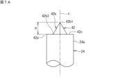
- FIG. 7A is a side view of a tip portion of an ejector pin according to a modified example.
- 7B is a plan view of a first end surface of the ejector pin in FIG. 7A.
- FIG. 8A is a side view of a tip portion of an ejector pin according to another modified example.
- FIG. 8B is a side view of a tip portion of an ejector pin according to still another modified example.
- FIG. 9A is a graph showing the detection results of the central pressure sensor in the comparative example.
- FIG. 9B is a graph showing the detection results of the central pressure sensor in the example.
- An embodiment of an injection molding machine includes a first mold, a second mold that defines an internal space of the mold between the first mold and the second mold and has a through hole that opens into the internal space of the mold, a cylindrical ejector pin that is movably inserted into the through hole and has a first end face that faces the internal space of the mold, and a pressure sensor provided on a second end face side of the ejector pin opposite to the first end face.
- the first end face has a periphery that is connected to a side face of the ejector pin and a protruding portion that protrudes in the axial direction beyond the periphery.
- the first end face facing the internal space of the mold has a protruding portion that protrudes in the axial direction. Therefore, compared to, for example, a case in which the first end face is a plane perpendicular to the axial direction, the area of the entire first end face can be relatively increased, and the pressure-receiving area for the molten resin in the internal space of the mold can be relatively increased. Therefore, even if a situation arises in which an error occurs in the detection result of the pressure sensor due to a cold slug approaching or contacting the first end face, the effect of the error caused by the cold slug can be reduced. As a result, the pressure in the internal space of the mold can be stably detected with reduced variation.
- the protrusion may have a central axis coinciding with a central axis of the ejector pin and may have a conical shape or a regular polygonal cone shape tapering from the periphery side toward the tip side of the protrusion. In this case, the protrusion can be easily released from the molded product.
- the protrusion may have a shape having a tapered side surface that tapers from the periphery toward the tip of the protrusion. In this case as well, the protrusion can be easily released from the molded product.
- the first end surface further has an annular end surface extending from the periphery toward a radially inner side of the ejector pin and connecting between a base end of the protrusion and the periphery.
- the ratio of the height of the protrusion in a direction along the central axis of the ejector pin to the radius of a circumscribing circle with respect to the contour shape of a cross section of the protrusion along the periphery be greater than or equal to 1/3 and less than or equal to 3. If the ratio is less than 1/3, the amount of protrusion of the protrusion is small, and the area of the entire first end face may not be increased sufficiently, whereas if the ratio is more than 3, the height of the protrusion becomes greater than necessary, and there is a risk of the protrusion buckling. By setting the ratio to be 1/3 or more and 3 or less, an ejector pin having a protruding portion of an appropriate height can be obtained.
- the internal space of the mold includes a spool forming space provided in the first mold, a runner forming space extending radially from the spool forming space, a gate connected to a tip end of the runner forming space, and a cavity connected to the gate,
- the through hole be provided along an extension direction of the spool forming space and form a cold slug well together with the first end surface.
- the protrusion can be provided inside the cold slug well, and the protrusion can be provided without affecting the molded product.
- FIG. 1 is a diagram showing an overall configuration of an injection molding machine according to an embodiment.
- the injection molding machine 1 is a device having a function of performing injection molding of a resin molded product.
- the injection molding machine 1 includes an injection unit 2, a mold clamping unit 4, a mold section 6, and a control device 8.
- the injection unit 2 is a unit for injecting molten resin into the mold portion 6 .
- the mold section 6 is a mold for forming a molded product.
- the mold section 6 has a first mold 21 and a second mold 22.
- the mold clamping unit 4 performs mold clamping by moving the first mold 21 and the second mold 22 relative to each other.
- the control device 8 has a function of controlling each unit to perform injection molding of the molded product.
- the control device 8 also has a function of detecting abnormalities when forming the molded product.
- the direction along the top-to-bottom direction of the paper is referred to as the axial direction
- the end of the injection molding machine 1 on the injection unit 2 side in the axial direction is referred to as the first end 1a
- the end opposite the first end 1a in the axial direction is referred to as the second end 1b
- the direction toward the first end 1a in the axial direction is also referred to as one axial side (first direction)
- the direction toward the second end 1b in the axial direction is also referred to as the other axial side (second direction).
- the injection unit 2 has a hopper 12 , a cylinder 14 , a screw 15 , and a heater 18 .
- the hopper 12 has a function of storing the resin pellets to be supplied into the cylinder 14 .
- the cylinder 14 is a cylindrical member extending along the axial direction.
- the screw 15 is inserted inside the cylinder 14.
- the cylinder 14 has an injection port 14b provided at the tip 14a and a storage space 14c.
- the storage space 14c is a space between the tip 14a and the tip of the screw 15. Molten resin obtained by melting resin pellets is stored in the storage space 14c.
- the injection port 14b is an opening for injecting the molten resin in the storage space 14c.
- the screw 15 is inserted into the cylinder 14 so as to be movable along the axial direction within the cylinder 14 and rotatable about its axis.
- the heater 18 is provided on the outer surface of the cylinder 14. The heater 18 heats the resin pellets supplied into the cylinder 14.
- the hopper 12 is connected to the internal space of the cylinder 14.
- the resin pellets stored in the hopper 12 are supplied to the storage space 14c of the cylinder 14 as the screw 15 rotates about its axis.
- the resin pellets are measured based on the rotation speed and rotation time of the screw 15, and a required amount of the resin pellets is supplied to the storage space 14c.
- the resin pellets in the storage space 14c are melted by heating with the heater 18.
- the resin pellets in the storage space 14c are heated by the heater 18 to become molten resin.
- the molten resin in the storage space 14c is injected from the injection port 14b by the movement along the axial direction of the screw 15. When injecting the molten resin, the screw 15 moves toward the tip 14a.
- the injection amount, injection speed, and injection pressure of the molten resin are controlled by the movement amount and movement speed of the screw 15.
- the injection port 14b is connected to an opening 6a of the mold portion 6. Therefore, the molten resin injected from the injection port 14b is supplied to the mold portion 6.
- the mold clamping unit 4 has a fixed platen 4a, a movable platen 4b, a plurality of tie bars 4c, and a drive unit 4d.
- the injection unit 2 is fixed to the fixed platen 4a, and the first mold 21 of the mold section 6 is fixed to the fixed platen 4a.
- the injection unit 2 is fixed to the first surface 4a1 of the fixed platen 4a.
- the first mold 21 is fixed to the second surface 4a2 of the fixed platen 4a.
- the first surface 4a1 is a surface facing one axial side of the fixed platen 4a.
- the second surface 4a2 is a surface facing the other axial side of the fixed platen 4a.
- the injection unit 2 is held in a state in which it penetrates the fixed platen 4a in the axial direction, thereby connecting the injection port 14b and the opening 6a.
- the movable platen 4b is capable of moving relative to the fixed platen 4a in the axial direction.
- the second mold 22 of the mold portion 6 is fixed to the movable platen 4b.
- the second mold 22 is fixed to a first surface 4b1 of the movable platen 4b.
- a movable mechanism 16 for axially moving an ejector pin 24 (described later) of the mold portion 6 is provided on the second surface 4b2 of the movable platen 4b.
- the movable mechanism 16 includes an actuator for axially moving the ejector pin 24.
- the first surface 4b1 faces one axial side of the movable platen 4b, and the second surface 4b2 faces the other axial side of the movable platen 4b.
- the tie bars 4c are rod-shaped members extending along the axial direction. One axial end of each of the tie bars 4c is fixed to the fixed platen 4a. The tie bars 4c guide the movable platen 4b in the
- the drive unit 4d has a function of moving the movable platen 4b relative to the fixed platen 4a.
- the drive unit 4d has a main body 4d1 and a plurality of shafts 4d2. The other axial ends of the plurality of tie bars 4c are fixed to the main body 4d1.
- the multiple shafts 4d2 are provided between the main body 4d1 and the movable platen 4b.
- the main body 4d1 has an actuator that moves the multiple shafts 4d2 in the axial direction.
- the main body 4d1 moves the multiple shafts 4d2 in the axial direction, thereby moving the movable platen 4b relative to the fixed platen 4a. Therefore, the drive unit 4d has the function of clamping and opening the mold unit 6.
- the mold section 6 includes the first mold 21, the second mold 22, and the ejector pin 24.
- the first mold 21 and the second mold 22 are combined with each other.
- An internal space 30 of the mold is defined between the first mold 21 and the second mold 22 that are combined with each other.
- the ejector pin (ejector pin) 24 is inserted into a through hole 40 of the second mold 22.
- the through hole 40 opens into the internal space 30 of the mold.
- the through hole 40 communicates between the inner end surface 22a and the outer end surface 22b.
- the through hole 40 is provided along the extension direction of a spool forming space 32 (described later) of the first mold 21.
- the inner end surface 22a is the surface of the second mold 22 facing into the internal space 30 of the mold.
- the outer end surface 22b is the surface opposite to the inner end surface 22a, and is the surface that abuts against and is fixed to the movable platen 4b.
- the ejector pin 24 is a cylindrical pin, and is movably inserted into the through hole 40.
- the ejector pin 24 has a first end surface 42 that faces the internal space 30 of the mold.
- the ejector pin 24 is provided to penetrate the second mold 22 and the movable platen 4b.
- the ejector pin 24 is driven by the movable mechanism 16 and moves in the axial direction relative to the second mold 22 and the movable platen 4b.
- Fig. 2A is a cross-sectional view showing only the mold part 6 in Fig. 1.
- Fig. 2B is a cross-sectional view taken along line II-II in Fig. 2A.
- the internal space 30 of the mold includes a spool forming space 32, a plurality of runner forming spaces 34 (four in the illustrated example), a plurality of gates 35 (four in the illustrated example), and a cavity 36.
- the spool forming space 32 is provided in the first mold 21. One axial end of the spool forming space 32 is connected to the opening 6a.
- the spool forming space 32 is a space in the shape of a truncated cone extending in the axial direction from the opening 6a. In the spool forming space 32, the spool of the molded product is formed.
- the cavity 36 is the space in which the product portion of the molded product is formed.
- the product portion is a circular ring-shaped member. Therefore, the cavity 36 is circular in shape to correspond to the product portion.
- the cavity 36 is formed between the first mold 21 and the second mold 22.
- the multiple runner forming spaces 34 are spaces in which runners of the molded product are formed.
- the multiple runner forming spaces 34 extend radially from the spool forming space 32.
- the angle between a pair of adjacent runner forming spaces 34 among the four runner forming spaces 34 is a right angle.
- the ends of the runner forming spaces 34 have gates 35.
- the gates 35 open into a cavity 36.
- the plurality of runner forming spaces 34 communicate with the spool forming space 32 and the cavity 36 .
- the internal space 30 of the mold further includes a cold slug well 38.
- the cold slug well 38 is a bottomed cylindrical space that extends axially on the other side of the multiple runner forming spaces 34.
- the cold slug well 38 extends along the extension direction of the spool forming space 32.
- the cold slug well 38 is defined by a through hole 40 of the second die 22 and a first end surface 42 of the ejector pin 24.
- the cold slug well 38 is recessed with respect to the inner end surface 22a.
- the second mold 22 is provided with a plurality of pressure sensors 44 (four in the illustrated example).
- the pressure sensors 44 are provided at positions facing the cavity 36.
- the pressure sensors 44 are provided at equal intervals in the circumferential direction in correspondence with the circumferential positions of the four runner forming spaces 34.
- the multiple pressure sensors 44 include piezoelectric elements or the like and have the function of detecting pressure on a detection surface.
- the detection surfaces of the multiple pressure sensors 44 face the cavity 36.
- the multiple pressure sensors 44 detect the pressure inside the cavity 36.
- the multiple pressure sensors 44 are connected to the control device 8.
- the outputs of the multiple pressure sensors 44 are provided to the control device 8.
- the ejector pin 24 is provided with a central pressure sensor 46 .
- the central pressure sensor 46 is provided on the second end surface 43 side of the ejector pin 24.
- the second end surface 43 of the ejector pin 24 is an end surface opposite to the first end surface 42.
- the central pressure sensor 46 includes a piezoelectric element or the like and has the function of detecting pressure on a detection surface.
- the central pressure sensor 46 is provided between the second end surface 43 and the movable mechanism 16. The detection surface of the central pressure sensor 46 abuts against the second end surface 43.
- the central pressure sensor 46 detects the pressure in the internal space 30 (cold slug well 38) of the mold via the ejector pin 24.
- the central pressure sensor 46 is connected to the control device 8.
- the output of the central pressure sensor 46 is provided to the control device 8.
- a control device 8 controls each unit to perform injection molding of a molded product. That is, the control device 8 first causes the mold clamping unit 4 to clamp the mold part 6. Next, the control device 8 causes the injection unit 2 to inject molten resin. At this time, the molten resin is injected from the opening 6a into the inside of the mold section 6. The molten resin injected into the mold section 6 passes through the spool forming space 32 and the plurality of runner forming spaces 34, and further passes through the plurality of gates 35 to reach the cavity 36. As a result, the molten resin is filled throughout the entire internal space 30 of the mold.
- the control device 8 When the molten resin is filled into the internal space 30 of the mold, the control device 8 maintains the pressure in the internal space 30 of the mold constant for a predetermined period of time. During this time, the molten resin in the internal space 30 of the mold solidifies. Thereafter, the control device 8 opens the mold section 6. A molded product is removed from the mold section 6 after the mold opening.
- the control device 8 controls each part based on the output of the multiple pressure sensors 44 and the central pressure sensor 46, and controls the injection unit 2 so that the molten resin is filled into the internal space 30 of the mold under appropriate conditions. In addition, the control device 8 performs processing to detect abnormalities that occur when the molten resin is injected and filled, based on the output of the central pressure sensor 46.
- FIG. 3 is a cross-sectional view showing the mold part 6 in an open state. 3, the first mold 21 and the second mold 22 are separated from each other, so that the molded product 50 is exposed.
- the molded product 50 includes a spool 50a, a plurality of runners 50b, a product portion 50c, and a protrusion portion 50d.
- the molded product 50 is exposed in a state where it is fixed to the second mold 22.
- the protrusion 50d is a protrusion formed by the cold slug well 38.
- the control device 8 controls the movable mechanism 16 to move the ejector pin 24 to one side in the axial direction.
- the ejector pin 24 moves along the through hole 40 to one side in the axial direction and presses the protrusion 50d of the molded product 50 to one side in the axial direction.
- the molded product 50 is pressed axially to one side by the first end surface 42 of the ejector pin 24 .
- the molded product 50 adhered to the second mold 22 is released from the second mold 22 . In this manner, the injection molding machine 1 forms the molded product 50 .
- Fig. 4A is a partial cross-sectional view of the second mold 22 showing a main portion of the ejector pin 24 of this embodiment.
- Fig. 4B is a plan view of the first end surface 42 of the ejector pin 24 in Fig. 4A.
- the cold slug well 38 is recessed with respect to the inner end surface 22 a of the second die 22 .
- a first end surface 42 of the ejector pin 24, which is the bottom surface of the cold slug well 38 has a peripheral edge 42a, a protruding portion 42b, and an annular end surface 42c.
- the peripheral edge 42 a is an edge portion that connects to the side surface 24 a of the ejector pin 24 at the first end surface 42 .
- the protruding portion 42b protrudes toward one side in the axial direction beyond the peripheral edge 42a.
- the protruding portion 42b has a conical shape whose central axis coincides with the central axis c of the ejector pin 24.
- the conical shape of the protruding portion 42b tapers from the circumferential edge 42a toward a tip 42b1 of the protruding portion 42b.
- the protrusion 42b has a tapered side surface 42b2 that tapers from the periphery 42a toward the tip 42b1. Since the protrusion 42b has a conical shape, the protrusion 42b can be easily released from the molded product 50.
- the annular end surface 42c is a surface that extends from the peripheral edge 42a toward the inside in the radial direction of the ejector pin 24 and connects between the base end of the protruding portion 42b and the peripheral edge 42a.
- the annular end surface 42c is a flat surface along the radial direction. In this way, since the first end face 42 has an annular end face 42c, when the ejector pin 24 releases the molded product 50 from the second mold 22, the ejector pin 24 can reliably press the molded product 50 along the axial direction.
- the area of the entire first end face 42 can be relatively increased compared to, for example, a case in which the first end face 42 is a plane perpendicular to the axial direction, and the ejector pin 24 can relatively increase the pressure-receiving area for the molten resin in the internal space 30 of the mold. Therefore, even if a situation occurs in which an error occurs in the detection result of the central pressure sensor 46 due to a cold slug approaching or contacting the first end face 42, the effect of the error caused by the cold slug can be reduced. As a result, the pressure in the internal space 30 of the mold can be stably detected with reduced variation.
- the ratio of the height H of the protrusion 42b to the radius of the circumscribing circle with respect to the contour shape of the cross section of the protrusion 42b along the circumscribing edge 42a is preferably 1/3 or more and 3/10 or less.
- the height H is the height of the protrusion 42b in the direction along the central axis c.
- the contour shape and circumscribing circle of the cross section of the protrusion 42b along the periphery 42a are the contour shape of the base end 42b3 of the protrusion 42b.
- the contour shape of the base end 42b3 is a circle with a diameter D. Therefore, in this embodiment, it is preferable that the height H and the diameter D of the protrusion 42b satisfy the relationship shown in the following formula (1).
- H: (D/2) 1/3 to 3...(1)
- the ratio is smaller than 1/3, the amount of protrusion of the protrusion 42b is small, and there is a risk of not being able to sufficiently increase the area of the entire first end face 42. If the ratio is larger than 3, the height of the protrusion 42b becomes higher than necessary, and there is a risk of the protrusion 42b buckling. By setting the ratio to be 1/3 or more and 3 or less, it is possible to provide the ejector pin 24 having the protrusion 42b of an appropriate height.
- the through hole 40 and the first end surface 42 form the cold slug well 38, but even in this case, since the first end surface 42 has a protrusion 42b, the pressure inside the internal space 30 of the mold can be detected with greater accuracy. Furthermore, since the protrusion 42b can be provided inside the cold slug well 38, the protrusion 42b can be provided without affecting the molded product 50.
- FIG. 5 is a block diagram showing the configuration of the control device 8.
- the control device 8 includes a processing unit 8a and a storage unit 8b.
- the processing unit 8a is, for example, one of various processors suitable for computer control, such as a CPU (Central Processing Unit) or a GPU (Graphics Processing Unit).
- the storage unit 8b is, for example, a flash memory, a hard disk, or a ROM (Read Only Memory).
- the storage unit 8b stores computer programs to be executed by the processing unit 8a and necessary information.
- the processing unit 8a executes computer programs stored in a computer-readable non-transitory recording medium such as the storage unit 8b to realize various processing functions of the control device 8.
- control device 8 is connected to a plurality of pressure sensors 44 and a central pressure sensor 46.
- the control device 8 receives output signals from these sensors.
- the processing unit 8a obtains the pressure of the central pressure sensor 46 based on output signals from the multiple pressure sensors 44 and the central pressure sensor 46, and controls each unit to cause each unit to perform injection molding. As described above, the processing unit 8a determines the pressure of the central pressure sensor 46 based on the output signal from the central pressure sensor 46, and executes the abnormality detection process.
- the abnormality detection process is a process for detecting an abnormality that occurs when the molten resin is injected and filled.
- FIG. 6 is a graph showing the change in pressure in the internal space 30 of the mold obtained from the output of the central pressure sensor 46 during injection molding. 6, the horizontal axis indicates time, and the vertical axis indicates pressure obtained from the output signal of the central pressure sensor 46.
- line L1 is a graph showing pressure changes in a normal case
- line L2 is a graph showing pressure changes in a case where a part of the gate 35 is clogged.
- Time t1 is the time when the filling of the molten resin begins. After time t1, processing unit 8a fills the molten resin into the internal space 30 of the mold. Therefore, immediately after time t1, no increase in pressure is observed, but once the molten resin has filled the internal space 30 of the mold to a certain extent, the pressure increases rapidly.
- processing unit 8a keeps the pressure in the internal space 30 of the mold constant and maintains the pressure for a predetermined time. When the predetermined time has elapsed, at time t3, processing unit 8a stops maintaining the pressure.
- the processing conditions for the injection molding according to the line L1 and the injection molding according to the line L2 are all the same except for a partial blockage of the gate 35.
- the pressure indicated by line L2 is higher than that indicated by line L1.
- the abnormality detection process is performed by detecting such an increase in pressure in the internal space 30 of the mold.
- the processing unit 8a detects an abnormality based on whether the pressure based on the signal detected by the central pressure sensor 46 between time t2 and time t3 is greater than a predetermined threshold value.
- the processor 8a compares the pressure measured by the central pressure sensor 46 at a certain time with a threshold value at a certain time between time t2 and time t3. If the pressure is greater than the threshold value, the processor 8a determines that there is an abnormality. Conversely, if the pressure is equal to or less than the threshold value, the processor 8a determines that there is a normality. In this manner, an abnormality is detected based on the pressure obtained from the output signal from the central pressure sensor 46 .
- the injection molding machine 1 of this embodiment can stably detect the pressure within the internal space 30 of the mold with reduced variation using the central pressure sensor 46, thereby improving the detection accuracy in the abnormality detection process.
- Fig. 7A is a side view of a tip portion of an ejector pin 24 according to a modified example
- Fig. 7B is a plan view of a first end surface 42 of the ejector pin 24 in Fig. 7A.
- This modification differs from the above embodiment in that the protruding portion 42b has a square pyramid shape.
- the protruding portion 42b has a regular square pyramid shape whose central axis coincides with the central axis c of the ejector pin 24.
- the square pyramid shape of the protruding portion 42b tapers from the periphery 42a side toward the tip 42b1 of the protruding portion 42b. In this embodiment as well, the pressure within the internal space 30 of the mold can be detected stably with reduced variation.
- the cross-sectional contour shape of the protruding portion 42b along the periphery 42a is the contour shape of the base end portion 42b3 of the protruding portion 42b, which is a square.
- the height H of the protrusion 42b and the diameter D of the circumscribing circle E for the contour shape of the base end 42b3 of the protrusion 42b satisfy the relationship of the above formula (1). Therefore, in this embodiment as well, it is possible to obtain the ejector pin 24 having the protrusion 42b with an appropriate height.
- FIG. 8A is a side view of a tip portion of an ejector pin 24 according to another modified example.
- This modified example differs from the above embodiment in that the first end surface 42 does not have an annular end surface 42c.
- the protrusion 42 b has a conical shape whose central axis coincides with the central axis c of the ejector pin 24 .
- FIG. 8B is a side view of the tip portion of an ejector pin 24 according to yet another modified example.
- This modification differs from the above embodiment in that the protruding portion 42b has a truncated cone shape.
- the truncated cone shape of the protrusion 42 b has a tip surface 42 b 4 , and the central axis coincides with the central axis c of the ejector pin 24 .
- the side surface 42b2 of the protruding portion 42b is tapered from the peripheral edge 42a toward the tip surface 42b4.
- the pressure within the internal space 30 of the mold can be detected stably with reduced variation.
- an ejector pin 24 is exemplified in which the protrusion 42b has a tapered side surface 42b2 that tapers from the periphery 42a toward the tip, but the protrusion 42b may also be cylindrical or prismatic.
- the first end surface 42 of the ejector pin 24 forms the bottom surface of the cold slug well 38, but the ejector pin 24 may be provided at a location other than the cold slug well 38.
- an ejector pin having a protrusion at the pressure sensor 44 may be used, and pressure may be detected via this ejector pin.
- the pressures used for comparison were obtained as follows. That is, in the examples and comparative examples, the output signal of the central pressure sensor 46 detected at a predetermined timing when normal injection molding was performed was obtained, and the pressure was calculated based on the output signal.
- the predetermined timing is a preset timing within a predetermined time during which the pressure in the internal space of the mold is kept constant. Injection molding according to the embodiment and injection molding according to the comparative example were each performed 20 times to obtain pressure values, and the variations in pressure were compared.
- Fig. 9A is a graph showing the pressure obtained from the output signal of the central pressure sensor 46 in a comparative example.
- Fig. 9B is a graph showing the pressure obtained from the output signal of the central pressure sensor 46 in an example.
- the vertical axis in Figures 9A and 9B indicates the pressure obtained from the output signal of the central pressure sensor 46, and the horizontal axis indicates an identification number for identifying which of the 20 injection moldings performed corresponds to which injection molding.
- the dotted line in FIG. 9A and the dotted line in FIG. 9B indicate the same predetermined pressure P1.
- the pressure in the comparative example fluctuates, with the value increasing and decreasing around pressure P1.
- FIG. 9B it can be seen that the pressure in the embodiment is stable around pressure P1 and the variation is suppressed compared to the comparative example. From these results, it became clear that by using the injection molding machine 1 of the embodiment, the pressure in the internal space of the mold can be detected stably with reduced variation.
Landscapes
- Engineering & Computer Science (AREA)
- Mechanical Engineering (AREA)
- Manufacturing & Machinery (AREA)
- Moulds For Moulding Plastics Or The Like (AREA)
- Injection Moulding Of Plastics Or The Like (AREA)
Priority Applications (2)
| Application Number | Priority Date | Filing Date | Title |
|---|---|---|---|
| JP2025502078A JPWO2024176461A1 (https=) | 2023-02-24 | 2023-02-24 | |
| PCT/JP2023/006850 WO2024176461A1 (ja) | 2023-02-24 | 2023-02-24 | 射出成形機 |
Applications Claiming Priority (1)
| Application Number | Priority Date | Filing Date | Title |
|---|---|---|---|
| PCT/JP2023/006850 WO2024176461A1 (ja) | 2023-02-24 | 2023-02-24 | 射出成形機 |
Publications (1)
| Publication Number | Publication Date |
|---|---|
| WO2024176461A1 true WO2024176461A1 (ja) | 2024-08-29 |
Family
ID=92500450
Family Applications (1)
| Application Number | Title | Priority Date | Filing Date |
|---|---|---|---|
| PCT/JP2023/006850 Ceased WO2024176461A1 (ja) | 2023-02-24 | 2023-02-24 | 射出成形機 |
Country Status (2)
| Country | Link |
|---|---|
| JP (1) | JPWO2024176461A1 (https=) |
| WO (1) | WO2024176461A1 (https=) |
Citations (9)
| Publication number | Priority date | Publication date | Assignee | Title |
|---|---|---|---|---|
| JPS5150357A (en) * | 1974-10-30 | 1976-05-01 | Hitachi Ltd | Jushifuji niokeru ryohinhanbetsuhoho oyobisono sochi |
| JPS60125112U (ja) * | 1984-02-01 | 1985-08-23 | 株式会社東芝 | 射出成形用金型 |
| JPH01122914U (https=) * | 1988-02-15 | 1989-08-21 | ||
| JPH07290516A (ja) * | 1994-04-20 | 1995-11-07 | Fuji Photo Film Co Ltd | 射出成形金型及び射出成形方法 |
| JPH0994834A (ja) * | 1995-10-02 | 1997-04-08 | Hitachi Ltd | 樹脂成形装置およびそれを用いて製造した半導体集積回路装置 |
| JPH1076554A (ja) * | 1996-09-04 | 1998-03-24 | Futaba Corp | 圧力センサ付エジェクタピン |
| JP2002086500A (ja) * | 2000-09-12 | 2002-03-26 | Futaba Corp | 不良品の検出方法及び装置並びに成形装置。 |
| JP2008012740A (ja) * | 2006-07-04 | 2008-01-24 | Ricoh Co Ltd | 射出成形金型装置 |
| JP2013515630A (ja) * | 2009-12-23 | 2013-05-09 | アールジェイジー,インク. | モールドを機械加工することなく、間接的及び直接的なモールドの圧力、温度、及びフローフロントの検出センサーを導入する新規な方法 |
-
2023
- 2023-02-24 JP JP2025502078A patent/JPWO2024176461A1/ja active Pending
- 2023-02-24 WO PCT/JP2023/006850 patent/WO2024176461A1/ja not_active Ceased
Patent Citations (9)
| Publication number | Priority date | Publication date | Assignee | Title |
|---|---|---|---|---|
| JPS5150357A (en) * | 1974-10-30 | 1976-05-01 | Hitachi Ltd | Jushifuji niokeru ryohinhanbetsuhoho oyobisono sochi |
| JPS60125112U (ja) * | 1984-02-01 | 1985-08-23 | 株式会社東芝 | 射出成形用金型 |
| JPH01122914U (https=) * | 1988-02-15 | 1989-08-21 | ||
| JPH07290516A (ja) * | 1994-04-20 | 1995-11-07 | Fuji Photo Film Co Ltd | 射出成形金型及び射出成形方法 |
| JPH0994834A (ja) * | 1995-10-02 | 1997-04-08 | Hitachi Ltd | 樹脂成形装置およびそれを用いて製造した半導体集積回路装置 |
| JPH1076554A (ja) * | 1996-09-04 | 1998-03-24 | Futaba Corp | 圧力センサ付エジェクタピン |
| JP2002086500A (ja) * | 2000-09-12 | 2002-03-26 | Futaba Corp | 不良品の検出方法及び装置並びに成形装置。 |
| JP2008012740A (ja) * | 2006-07-04 | 2008-01-24 | Ricoh Co Ltd | 射出成形金型装置 |
| JP2013515630A (ja) * | 2009-12-23 | 2013-05-09 | アールジェイジー,インク. | モールドを機械加工することなく、間接的及び直接的なモールドの圧力、温度、及びフローフロントの検出センサーを導入する新規な方法 |
Also Published As
| Publication number | Publication date |
|---|---|
| JPWO2024176461A1 (https=) | 2024-08-29 |
Similar Documents
| Publication | Publication Date | Title |
|---|---|---|
| JP7205225B2 (ja) | 成形条件決定支援装置および射出成形機 | |
| WO2024176461A1 (ja) | 射出成形機 | |
| JP7297215B2 (ja) | 演算装置、演算処理プログラム、および演算方法 | |
| JP7826842B2 (ja) | 射出成形装置 | |
| JP5102186B2 (ja) | 射出成形方法および射出成形機 | |
| JPH03218810A (ja) | 射出成形機の充填量検出方法 | |
| JPH02202420A (ja) | 射出成形での可塑材料の圧力測定方法および射出成形機 | |
| JP4367172B2 (ja) | 射出装置及び射出成形方法 | |
| JP2901010B2 (ja) | 射出成形機の運転方法 | |
| US20160200021A1 (en) | Compression controller of injection molding machine | |
| JPH053815B2 (https=) | ||
| JP5052246B2 (ja) | 射出成形機 | |
| JPH0749213B2 (ja) | 射出成形機の成形品良品判別方法 | |
| JPS6290212A (ja) | 樹脂成形方法およびその装置 | |
| JP2908091B2 (ja) | 射出成形機の逆流防止弁 | |
| JPH0314338Y2 (https=) | ||
| JP2025086148A (ja) | 射出装置及び射出成形機 | |
| CN121816254A (zh) | 注射成型机 | |
| JPS6125816A (ja) | 射出成形方法および射出成形機 | |
| JP2514272Y2 (ja) | 射出成形機の逆流防止弁 | |
| US20210387391A1 (en) | Independent startup mode for injection molding | |
| WO2025105336A1 (ja) | 射出成形機及び型内圧の検出方法 | |
| JPH08323825A (ja) | 射出成形装置 | |
| JP3317653B2 (ja) | 射出成形機の射出速度制御装置 | |
| JP2005119000A (ja) | ゴム射出成形システム及びゴム射出成形システム用射出成形加硫条件設定方法 |
Legal Events
| Date | Code | Title | Description |
|---|---|---|---|
| 121 | Ep: the epo has been informed by wipo that ep was designated in this application |
Ref document number: 23923224 Country of ref document: EP Kind code of ref document: A1 |
|
| WWE | Wipo information: entry into national phase |
Ref document number: 2025502078 Country of ref document: JP |
|
| NENP | Non-entry into the national phase |
Ref country code: DE |
|
| 122 | Ep: pct application non-entry in european phase |
Ref document number: 23923224 Country of ref document: EP Kind code of ref document: A1 |