WO2024171939A1 - 誘電体磁器組成物および積層セラミック電子部品 - Google Patents
誘電体磁器組成物および積層セラミック電子部品 Download PDFInfo
- Publication number
- WO2024171939A1 WO2024171939A1 PCT/JP2024/004289 JP2024004289W WO2024171939A1 WO 2024171939 A1 WO2024171939 A1 WO 2024171939A1 JP 2024004289 W JP2024004289 W JP 2024004289W WO 2024171939 A1 WO2024171939 A1 WO 2024171939A1
- Authority
- WO
- WIPO (PCT)
- Prior art keywords
- mol
- ceramic composition
- dielectric ceramic
- titanium
- manganese
- Prior art date
- Legal status (The legal status is an assumption and is not a legal conclusion. Google has not performed a legal analysis and makes no representation as to the accuracy of the status listed.)
- Ceased
Links
Images





Classifications
-
- H—ELECTRICITY
- H01—ELECTRIC ELEMENTS
- H01G—CAPACITORS; CAPACITORS, RECTIFIERS, DETECTORS, SWITCHING DEVICES, LIGHT-SENSITIVE OR TEMPERATURE-SENSITIVE DEVICES OF THE ELECTROLYTIC TYPE
- H01G4/00—Fixed capacitors; Processes of their manufacture
- H01G4/30—Stacked capacitors
-
- C—CHEMISTRY; METALLURGY
- C04—CEMENTS; CONCRETE; ARTIFICIAL STONE; CERAMICS; REFRACTORIES
- C04B—LIME, MAGNESIA; SLAG; CEMENTS; COMPOSITIONS THEREOF, e.g. MORTARS, CONCRETE OR LIKE BUILDING MATERIALS; ARTIFICIAL STONE; CERAMICS; REFRACTORIES; TREATMENT OF NATURAL STONE
- C04B35/00—Shaped ceramic products characterised by their composition; Ceramics compositions; Processing powders of inorganic compounds preparatory to the manufacturing of ceramic products
- C04B35/01—Shaped ceramic products characterised by their composition; Ceramics compositions; Processing powders of inorganic compounds preparatory to the manufacturing of ceramic products based on oxide ceramics
- C04B35/46—Shaped ceramic products characterised by their composition; Ceramics compositions; Processing powders of inorganic compounds preparatory to the manufacturing of ceramic products based on oxide ceramics based on titanium oxides or titanates
- C04B35/462—Shaped ceramic products characterised by their composition; Ceramics compositions; Processing powders of inorganic compounds preparatory to the manufacturing of ceramic products based on oxide ceramics based on titanium oxides or titanates based on titanates
- C04B35/465—Shaped ceramic products characterised by their composition; Ceramics compositions; Processing powders of inorganic compounds preparatory to the manufacturing of ceramic products based on oxide ceramics based on titanium oxides or titanates based on titanates based on alkaline earth metal titanates
- C04B35/468—Shaped ceramic products characterised by their composition; Ceramics compositions; Processing powders of inorganic compounds preparatory to the manufacturing of ceramic products based on oxide ceramics based on titanium oxides or titanates based on titanates based on alkaline earth metal titanates based on barium titanates
- C04B35/4682—Shaped ceramic products characterised by their composition; Ceramics compositions; Processing powders of inorganic compounds preparatory to the manufacturing of ceramic products based on oxide ceramics based on titanium oxides or titanates based on titanates based on alkaline earth metal titanates based on barium titanates based on BaTiO3 perovskite phase
-
- H—ELECTRICITY
- H01—ELECTRIC ELEMENTS
- H01G—CAPACITORS; CAPACITORS, RECTIFIERS, DETECTORS, SWITCHING DEVICES, LIGHT-SENSITIVE OR TEMPERATURE-SENSITIVE DEVICES OF THE ELECTROLYTIC TYPE
- H01G4/00—Fixed capacitors; Processes of their manufacture
- H01G4/002—Details
- H01G4/005—Electrodes
- H01G4/012—Form of non-self-supporting electrodes
-
- H—ELECTRICITY
- H01—ELECTRIC ELEMENTS
- H01G—CAPACITORS; CAPACITORS, RECTIFIERS, DETECTORS, SWITCHING DEVICES, LIGHT-SENSITIVE OR TEMPERATURE-SENSITIVE DEVICES OF THE ELECTROLYTIC TYPE
- H01G4/00—Fixed capacitors; Processes of their manufacture
- H01G4/002—Details
- H01G4/018—Dielectrics
- H01G4/06—Solid dielectrics
- H01G4/08—Inorganic dielectrics
- H01G4/12—Ceramic dielectrics
- H01G4/1209—Ceramic dielectrics characterised by the ceramic dielectric material
- H01G4/1218—Ceramic dielectrics characterised by the ceramic dielectric material based on titanium oxides or titanates
- H01G4/1227—Ceramic dielectrics characterised by the ceramic dielectric material based on titanium oxides or titanates based on alkaline earth titanates
-
- H—ELECTRICITY
- H01—ELECTRIC ELEMENTS
- H01G—CAPACITORS; CAPACITORS, RECTIFIERS, DETECTORS, SWITCHING DEVICES, LIGHT-SENSITIVE OR TEMPERATURE-SENSITIVE DEVICES OF THE ELECTROLYTIC TYPE
- H01G4/00—Fixed capacitors; Processes of their manufacture
- H01G4/002—Details
- H01G4/228—Terminals
- H01G4/232—Terminals electrically connecting two or more layers of a stacked or rolled capacitor
-
- C—CHEMISTRY; METALLURGY
- C04—CEMENTS; CONCRETE; ARTIFICIAL STONE; CERAMICS; REFRACTORIES
- C04B—LIME, MAGNESIA; SLAG; CEMENTS; COMPOSITIONS THEREOF, e.g. MORTARS, CONCRETE OR LIKE BUILDING MATERIALS; ARTIFICIAL STONE; CERAMICS; REFRACTORIES; TREATMENT OF NATURAL STONE
- C04B2235/00—Aspects relating to ceramic starting mixtures or sintered ceramic products
- C04B2235/02—Composition of constituents of the starting material or of secondary phases of the final product
- C04B2235/30—Constituents and secondary phases not being of a fibrous nature
- C04B2235/32—Metal oxides, mixed metal oxides, or oxide-forming salts thereof, e.g. carbonates, nitrates, (oxy)hydroxides, chlorides
- C04B2235/3224—Rare earth oxide or oxide forming salts thereof, e.g. scandium oxide
-
- C—CHEMISTRY; METALLURGY
- C04—CEMENTS; CONCRETE; ARTIFICIAL STONE; CERAMICS; REFRACTORIES
- C04B—LIME, MAGNESIA; SLAG; CEMENTS; COMPOSITIONS THEREOF, e.g. MORTARS, CONCRETE OR LIKE BUILDING MATERIALS; ARTIFICIAL STONE; CERAMICS; REFRACTORIES; TREATMENT OF NATURAL STONE
- C04B2235/00—Aspects relating to ceramic starting mixtures or sintered ceramic products
- C04B2235/02—Composition of constituents of the starting material or of secondary phases of the final product
- C04B2235/30—Constituents and secondary phases not being of a fibrous nature
- C04B2235/32—Metal oxides, mixed metal oxides, or oxide-forming salts thereof, e.g. carbonates, nitrates, (oxy)hydroxides, chlorides
- C04B2235/3262—Manganese oxides, manganates, rhenium oxides or oxide-forming salts thereof, e.g. MnO
-
- C—CHEMISTRY; METALLURGY
- C04—CEMENTS; CONCRETE; ARTIFICIAL STONE; CERAMICS; REFRACTORIES
- C04B—LIME, MAGNESIA; SLAG; CEMENTS; COMPOSITIONS THEREOF, e.g. MORTARS, CONCRETE OR LIKE BUILDING MATERIALS; ARTIFICIAL STONE; CERAMICS; REFRACTORIES; TREATMENT OF NATURAL STONE
- C04B2235/00—Aspects relating to ceramic starting mixtures or sintered ceramic products
- C04B2235/02—Composition of constituents of the starting material or of secondary phases of the final product
- C04B2235/30—Constituents and secondary phases not being of a fibrous nature
- C04B2235/34—Non-metal oxides, non-metal mixed oxides, or salts thereof that form the non-metal oxides upon heating, e.g. carbonates, nitrates, (oxy)hydroxides, chlorides
- C04B2235/3418—Silicon oxide, silicic acids or oxide forming salts thereof, e.g. silica sol, fused silica, silica fume, cristobalite, quartz or flint
Definitions
- the present invention relates to a dielectric ceramic composition and a multilayer ceramic electronic component.
- Multilayer ceramic electronic components such as multilayer ceramic capacitors (MLCCs) are used in high-frequency communication systems such as mobile phones.
- MLCCs multilayer ceramic capacitors
- the dielectric ceramic composition used in the dielectric layers of multilayer ceramic electronic components uses a sintered body with a core-shell structure in which barium titanate is the core and is surrounded by a shell in which various additives are dissolved.
- This structure makes it possible to transition the large capacitance that occurs near the Curie temperature, around 125°C, where barium titanate changes from a ferroelectric phase to a paraelectric phase, to a lower temperature in the shell due to the effects of various additives, making it possible to design a device that further increases capacitance in the practical temperature range around room temperature.
- the core-shell structure is thought to be created by dissolving various additives in barium titanate.
- the core-shell structure is thought to be created when various additives react with the barium titanate particles (the main component) in a firing temperature range of, for example, 1000°C to 1400°C.
- the various additives dissolve and the shell becomes thicker. Therefore, in order to keep the capacitance of multilayer ceramic electronic components within the required range, the firing temperature must be precisely controlled.
- a piezoelectric ceramic containing at least one of Ba 4 Ti 12 O 27 and Ba 6 Ti 17 O 40 as a barium titanate composite oxide and further containing 0.04% by mass to 0.20% by mass of manganese in terms of metal relative to the barium titanate has been disclosed (see, for example, Patent Document 1).
- the present invention also includes a metal oxide represented by the formula (Ba1 -xCax ) a (Ti1 -yZry ) O3 (wherein 0.09 ⁇ x ⁇ 0.30, 0.025 ⁇ y ⁇ 0.085, and 0.986 ⁇ a ⁇ 1.020) and 0.04 parts by weight or more and 0.36 parts by weight or less of manganese calculated as a metal relative to 100 parts by weight of the metal oxide.
- a metal oxide represented by the formula (Ba1 -xCax ) a (Ti1 -yZry ) O3 (wherein 0.09 ⁇ x ⁇ 0.30, 0.025 ⁇ y ⁇ 0.085, and 0.986 ⁇ a ⁇ 1.020) and 0.04 parts by weight or more and 0.36 parts by weight or less of manganese calculated as a metal relative to 100 parts by weight of the metal oxide.
- the barium titanate composite oxide includes BaTi2O5 , BaTi4O9 , BaTi5O11 , BaTi6O13 , BaTi7O14 , BaTi8O16 , Ba2Ti5O12 , Ba2Ti6O13 , Ba2Ti Japanese Patent Application Laid- Open No.
- 2003-134633 discloses a piezoelectric ceramic containing at least one metal oxide selected from the group consisting of BaTiO20 , Ba4Ti11O26 , Ba4Ti13O30 , CaTi2O4 , CaTi2O5 , CaTi4O9 , Ca2Ti5O12 , CaZr4O9 , Ca2Zr7O16 , Ca6Zr19O44 , CaZrTi2O7 , and Ca2Zr5Ti2O16 .
- the present invention has been made in consideration of the above problems, and aims to provide a dielectric ceramic composition and a multilayer ceramic electronic component that can suppress changes in capacitance due to firing temperature.
- the dielectric ceramic composition according to the present invention has a perovskite structure represented by the general formula ABO3 , and comprises first crystal particles having a core portion and a shell portion covering the core portion and containing a rare earth element and manganese, and second crystal particles mainly composed of a barium titanate-based composite oxide in which the element ratio of barium to titanium is 0.70 or less.
- the rare earth element may be at least one selected from gadolinium, europium, terbium, dysprosium, holmium, erbium, and ytterbium.
- the element ratio of barium to titanium may be 0.926 or more and 0.995 or less
- the element ratio of the rare earth element to titanium may be 0.005 or more and 0.05 or less
- the element ratio of manganese to titanium may be 0.002 or more and 0.05 or less.
- the dielectric ceramic composition may further contain silicon having an elemental ratio of 0.002 to 0.05 relative to titanium, and magnesium having an elemental ratio of 0.00 to 0.05 relative to titanium.
- the elemental concentrations of the rare earth element and manganese in the shell portion may be greater than the elemental concentrations of the rare earth element and manganese in the core portion.
- the maximum grain size of the first crystal grains may be 2 ⁇ m or less.
- the second crystal particles may have an elemental ratio of barium to titanium of 0.16 or more.
- the second crystal particles may be at least one selected from BaTi2O5 , BaTi4O9 , BaTi5O11 , BaTi6O13 , Ba4Ti11O26 , Ba4Ti12O27 , Ba4Ti13O30 , and Ba6Ti17O40 .
- the dielectric ceramic composition may be such that the second crystal particles contain manganese, and the elemental ratio of manganese to titanium in the second crystal particles is 0.02 or more and 0.10 or less.
- the dielectric ceramic composition may be such that the second crystal particles contain manganese, and the elemental ratio of manganese to titanium in the second crystal particles is 0.02 or more and 0.05 or less.
- Another dielectric ceramic composition according to the present invention has a perovskite structure represented by the general formula ABO3 , and comprises first crystal particles having a core portion and a shell portion covering the core portion and containing a rare earth element and manganese , and second crystal particles which are a barium titanate-based composite oxide represented by Ba4Ti11O26 , contain manganese, and have an element ratio of manganese to titanium of 0.02 or more and 0.10 or less.
- the rare earth element may be at least one selected from gadolinium, europium, terbium, dysprosium, holmium, erbium, and ytterbium.
- the element ratio of barium to titanium may be 0.926 or more and 0.995 or less
- the element ratio of the rare earth element to titanium may be 0.005 or more and 0.05 or less
- the element ratio of manganese to titanium may be 0.002 or more and 0.05 or less.
- the dielectric ceramic composition may further contain silicon having an elemental ratio of 0.002 to 0.05 relative to titanium, and magnesium having an elemental ratio of 0.00 to 0.05 relative to titanium.
- the elemental concentrations of the rare earth element and manganese in the shell portion may be greater than the elemental concentrations of the rare earth element and manganese in the core portion.
- the maximum grain size of the first crystal grains may be 2 ⁇ m or less.
- the element ratio of manganese to titanium in the second crystal particles may be 0.02 or more and 0.05 or less.
- the multilayer ceramic electronic component according to the present invention uses any of the dielectric ceramic compositions described above.
- the laminated ceramic electronic component includes a plurality of mutually opposing internal electrodes, a dielectric layer sandwiched between the plurality of internal electrodes and including the dielectric ceramic composition according to claim 1, and an external electrode electrically connected to the internal electrodes.
- the present invention provides a dielectric ceramic composition and a multilayer ceramic electronic component that can suppress changes in capacitance due to firing temperature.
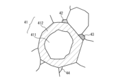
- FIG. 1 is a diagram illustrating a dielectric ceramic composition according to a first embodiment.
- FIG. FIG. 2 is a diagram illustrating a unit lattice.
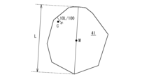
- FIG. 1 is a diagram illustrating a method for confirming a core-shell structure.
- FIG. 2 is a partial cross-sectional perspective view of a multilayer ceramic capacitor.
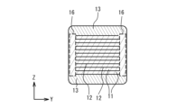
- 5 is a cross-sectional view taken along line AA in FIG. 4.
- 5 is a cross-sectional view taken along line BB in FIG. 4.
- 1 is a diagram illustrating a flow of a method for manufacturing a multilayer ceramic capacitor.
- 4A and 4B are diagrams illustrating an internal electrode forming step.
- 1A to 1C are diagrams illustrating a pressure bonding process.
- 11A and 11B are diagrams illustrating an example of a side margin portion.
- the dielectric ceramic composition according to the first embodiment is a ceramic polycrystalline body including crystal grains having a perovskite structure represented by the general formula ABO3 , as exemplified in Fig. 1.
- these ceramic polycrystalline bodies at least one is a first crystal grain 41 having a core-shell structure, and at least one is a second crystal grain 42 in which the element ratio of barium to titanium is 0.70 or less.
- the first crystal particle 41 has a core portion 411 having a substantially spherical shape and a shell portion 412 surrounding and covering the core portion 411.
- the core portion 411 is a crystal portion in which the additive compound is not dissolved or in which the amount of the additive compound dissolved is small.
- the shell portion 412 is a crystal portion in which the additive compound is dissolved and has a higher additive compound concentration than the additive compound concentration of the core portion 411.
- the shell portion 412 contains a rare earth element and manganese.
- the rare earth element is not particularly limited, but may be at least one selected from gadolinium, europium, terbium, dysprosium, holmium, erbium, and ytterbium.
- the elemental concentrations of the rare earth element and manganese in the shell portion 412 are greater than the elemental concentrations of the rare earth element and manganese in the core portion 411.
- the dielectric ceramic composition according to this embodiment contains the first crystal particles 41 and the second crystal particles 42, which makes it possible to suppress the change in capacitance due to the firing temperature.
- the area ratio of the first crystal particles 41 is 50% or more and 99.95% or less
- the area ratio of the second crystal particles 42 is 0.05% or more and 50% or less.
- the dielectric ceramic composition may contain third crystal grains 43 having a different composition or crystal structure, voids 44, etc.
- the area ratio of the third crystal grains 43 is 0.05% or more and 20% or less.
- Crystal particles having a perovskite structure which are the main component of the first crystal particles 41, have a unit lattice as shown in FIG. 2.
- This unit lattice has A sites located at the vertices of the lattice, O sites located at the face centers of the lattice, and B sites located within an octahedron with the O sites as vertices.
- alkaline earth metals that can take divalent cations such as barium (Ba), strontium (Sr), and calcium (Ca) are located at the A sites, and metal atoms that can take tetravalent cations, such as hafnium (Hf), zirconium (Zr), and titanium (Ti), are located at the B sites.
- the perovskite structure also allows for a composition formula that deviates from the stoichiometric composition. That is, the ratio of the A-site element to the B-site element does not necessarily have to be 1:1, and defects may be generated within a range that allows the perovskite structure to be maintained. Also, defects may be generated in oxygen. For example, when the composition formula is A ⁇ BO 3- ⁇ , a composition in the range of 0.98 ⁇ 1.01 and 0 ⁇ 0.20 is allowed.
- the first crystal particles 41 having a perovskite structure may contain at least one of the first transition elements scandium (Sc), titanium (Ti), vanadium (V), chromium (Cr), iron (Fe), cobalt (Co), nickel (Ni), copper (Cu), and zinc (Zn) as necessary. This can improve resistivity, increase electrical life, and reduce dielectric loss relative to capacitance.
- the first crystal particles 41 may also contain at least one of the second transition elements yttrium (Y), zirconium (Zr), niobium (Nb), molybdenum (Mo), ruthenium (Ru), rhodium (Rh), palladium (Pd), and silver (Ag) as necessary. This can improve resistivity, increase electrical life, and reduce dielectric loss relative to capacitance.
- the first crystal particles 41 may also contain at least one of the third transition elements lanthanum (La), cerium (Ce), praseodymium (Pr), neodymium (Nd), samarium (Sm), europium (Eu), gadolinium (Gd), terbium (Tb), dysprosium (Dy), holmium (Ho), erbium (Er), thulium (Tm), ytterbium (Yb), lutetium (Lu), hafnium (Hf), tantalum (Ta), tungsten (W), rhenium (Re), osmium (Os), iridium (Ir), platinum (Pt), and gold (Au), as necessary. This can improve resistivity, increase electrical life, and reduce dielectric loss relative to capacitance.
- This can improve resistivity, increase electrical life, and reduce dielectric loss relative to capacitance.
- the Ba/Ti element ratio x which is the element ratio of barium to the titanium content
- the Ba/Ti element ratio x which is the element ratio of barium to the titanium content
- the solid solution reaction with barium titanate crystal particles is relatively suppressed compared to when no additive containing titanium is added. Due to this effect, for example, by applying it to a multilayer ceramic capacitor, which requires high mass productivity, it is possible to achieve firing in a shorter time while suppressing the rate of change in capacitance due to changes in firing temperature, thereby achieving high mass productivity.
- the dielectric composition is added with 2.0 mol or more and 6.4 mol or less of titanium in terms of titanium oxide (TiO 2 ) per 100 mol of barium titanate so that the Ba/Ti element ratio x is 0.940 ⁇ x ⁇ 0.980.
- TiO 2 titanium oxide
- titanium-containing additive is titanium oxide, but titanium hydroxide (Ti(OH) 4 ), titanium chloride (TiCl 4 ), titanium carbide (TiC), titanium sulfide (TiS 2 ), etc. can also be used.
- gadolinium oxide Gd 2 O 3
- barium titanate it is preferable to add 0.25 mol or more and 2.5 mol or less of gadolinium in terms of gadolinium oxide (Gd 2 O 3 ) to 100 mol of barium titanate so that the Gd/Ti element ratio y, which is the element ratio of the rare earth element, for example, gadolinium, to the titanium content, satisfies 0.005 ⁇ y ⁇ 0.05.
- MnO manganese oxide
- the added gadolinium, manganese, and titanium react on the surface of the barium titanate crystal grains, and can be generated as the shell portion in the form of a composite perovskite compound considered to be Gd(Ti,Mn)O 3.
- the dielectric ceramic composition not only suppresses the change in capacitance caused by the change in firing temperature, but also suppresses the movement of oxygen defects in the grain boundaries and inside the shell portion, suppresses the decrease in resistivity, and improves the electrical life.
- the amounts of gadolinium and manganese are adjusted to satisfy 0.005 ⁇ y ⁇ 0.02 and 0.005 ⁇ z ⁇ 0.02. In this case, it becomes possible to suppress the excessive dissolution of excess gadolinium into crystal particles made of barium titanate in the dielectric ceramic composition, and the precipitation of excess manganese on the surface of the dielectric ceramic composition, thereby further suppressing the range of change in capacitance due to changes in firing temperature, and also making it possible to maintain a high resistivity.
- silicon may be added in an amount of 0.2 mol or more and 5.0 mol or less in terms of silicon oxide (SiO 2 ) so that the Si/Ti element ratio a, which is the element ratio of silicon to the titanium content, is 0.002 ⁇ a ⁇ 0.05.
- silicon oxide SiO 2
- Magnesium may be added in an amount of 0 mol or more and 5.0 mol or less in terms of magnesium oxide (MgO) so that the Mg/Ti element ratio b, which is the element ratio of magnesium to the titanium content, is 0.00 ⁇ b ⁇ 0.05.
- the dielectric ceramic composition generates first crystal particles 41 containing silicon or second crystal particles 42 that become glass particles, and generates a liquid phase inside during firing, making it possible to obtain dense ceramics at a lower temperature. Furthermore, by adding magnesium oxide, it becomes possible to generate the shell portion in the form of Gd(Mg,Ti,Mn) O3 or (Gd,Ba)(Mg,Ti,Mn) O3 , which further suppresses the movement of oxygen defects at the grain boundaries and inside the shell portion, and makes it possible to suppress a decrease in resistivity.
- 0.005 ⁇ a ⁇ 0.02 and 0.002 ⁇ b ⁇ 0.02 are desirable. At this time, it is possible to prevent excess additives from being generated as third crystal particles 43, and it is possible to suppress the decrease in the relative dielectric constant while achieving the effect of densification at low temperatures and suppressing the decrease in resistivity.
- rare earth elements such as cerium, praseodymium, neodymium, samarium, europium, gadolinium, terbium, dysprosium, holmium, erbium, thulium, ytterbium, and lutetium as additives among the first transition metal elements, the second transition metal elements, and the third transition metal elements, in the firing temperature range of 1000°C to 1400°C for obtaining a dielectric ceramic composition, the rare earth elements are dissolved from the interface to the inside of the first crystal particles 41, and crystal particles having a core-shell structure in which a shell portion and a core portion are generated can be obtained.
- rare earth elements such as cerium, praseodymium, neodymium, samarium, europium, gadolinium, terbium, dysprosium, holmium, erbium, thulium, ytterbium, and lutetium as additives among the first transition metal elements,
- the dielectric ceramic composition according to this embodiment is obtained by firing at 1000°C to 1300°C and by rapidly increasing the temperature during the firing process at a rate of 3000°C/h to 10000°C/h.
- the first crystal grains 41 having a core-shell structure in which a shell portion 412 containing a rare earth element and manganese is formed have a different formation process from conventional core-shell structures. Specifically, not only is the rare earth element dissolved in the crystal grains made of barium titanate, but the added rare earth element, manganese, and titanium react on the surface of the barium titanate crystal grains to form the shell portion in the form of a composite perovskite compound such as Gd(Ti,Mn) O3 .
- the shell portion 412 may be formed as a shell portion in the form of a composite perovskite compound such as Gd(Mg, Ti, Mn) O3 by reacting with the added magnesium on the surface of the barium titanate crystal particle.
- the shell portion 412 in the form of a composite perovskite compound thought to be Gd(Ti,Mn) O3 or Gd(Mg,Ti,Mn) O3 may be generated as the shell portion as (Gd,Ba)(Ti,Mn) O3 or (Gd,Ba)(Mg,Ti,Mn) O3 by reaction with the surrounding barium titanate crystal particles, which is the main component.
- the core portion 411 in the core-shell structure is mainly composed of crystal particles made of barium titanate, but may also contain added rare earth elements, manganese, magnesium, etc. However, it is sufficient that the shell portion 412 contains relatively more of the additives such as rare earth elements, manganese, magnesium, etc. than the core portion 411.
- crystal grains having a core-shell structure in which a shell containing gadolinium and manganese is formed with crystal grains made of barium titanate as the main component may contain a relatively large amount of gadolinium or manganese at any point within a range in which the distance from the surface toward the center is 10% of the diameter of the crystal grain in question, compared to the element ratio of gadolinium or manganese to titanium at the center.
- the presence of crystal grains having such a core-shell structure not only suppresses the range of change in capacitance retained due to changes in firing temperature, but also suppresses the movement of oxygen defects at grain boundaries and inside the shell, suppressing a decrease in resistivity and making it possible to improve electrical life.
- the average particle size of the first crystal particles 41 in the dielectric ceramic composition is within the range of 50 nm to 500 nm, and large particles of 3 ⁇ m or more are not retained in areas that are electrically utilized as a dielectric.
- the maximum particle size of the first crystal particles is preferably 2 ⁇ m or less. Also, in view of the general ceramic characteristic that the particle size and composition distribution of the contained crystal particles falls within a relatively narrow range, if it can be confirmed that the first crystal particles 41 have a core-shell structure, it can be said that the presence of a large number of first crystal particles 41 with a similar structure has a positive effect on the electrical life of the dielectric ceramic composition.
- the particle diameter of the first crystal particles 41 can be measured by the following procedure.
- the dielectric ceramic composition having the first crystal particles 41 is cut or polished to expose the observation surface.
- the exposure method is not particularly limited, and a method of cutting or polishing the element can be adopted.
- the surface is observed with a scanning electron microscope (SEM) and a photograph of the first crystal particles 41 is taken.
- SEM scanning electron microscope
- the grain size of the first crystal grains 41 is measured for 400 or more grains, and the average of the results is taken as the average grain size of the first crystal grains 41. If the outline of the first crystal grains 41 is difficult to see in the exposed ceramic, it is advisable to subject the exposed ceramic to a heat treatment (thermal etching) for about 5 minutes at a temperature about 50°C lower than the firing temperature prior to deposition of platinum or osmium. Instead of this heat treatment, it is also possible to chemically etch the ceramic using an acid such as hydrofluoric acid, hydrochloric acid, sulfuric acid, nitric acid, or a mixture of these acids at an appropriate concentration for etching.
- an acid such as hydrofluoric acid, hydrochloric acid, sulfuric acid, nitric acid, or a mixture of these acids at an appropriate concentration for etching.
- the core-shell structure of the first crystal grains 41 is formed as a shell portion in the form of a composite perovskite compound considered to be Gd(Ti,Mn)O 3 , or Gd(Mg,Ti,Mn)O 3 , or (Gd,Ba)(Ti,Mn)O 3 , or (Gd,Ba)(Mg,Ti,Mn)O 3 , by the reaction of the added gadolinium, manganese, and titanium on the surface of the barium titanate crystal grains.
- the added titanium is involved in the reaction, the solid-solution reaction with the barium titanate crystal grains is relatively suppressed compared to the case where no titanium is added. Due to this effect, by applying it to a multilayer ceramic capacitor, which is required to have high mass productivity, for example, it is possible to achieve firing in a shorter time while suppressing the change in capacitance due to changes in firing temperature, thereby achieving high mass productivity.
- first crystal particles 41 having a core-shell structure in the dielectric ceramic composition can be confirmed by the following procedure.
- TEM transmission electron microscope
- FIB focused ion beam
- the cut sample for TEM observation is observed using a TEM equipped with an energy dispersive X-ray spectrometer (EDS) or a wavelength dispersive X-ray spectrometer (WDS) to determine the crystal grains to be measured and to identify the peripheral shape of the grains.
- EDS energy dispersive X-ray spectrometer
- WDS wavelength dispersive X-ray spectrometer
- the longest line segment connecting any two points located on the outer periphery of the crystal particle to be measured is determined, and the length L of that line segment is measured. This length L is then taken as the diameter of the crystal particle to be measured. In addition, the midpoint M of the line segment is determined from the length of the line segment obtained.
- a composition analysis is performed by EDS or WDS for any point C on the periphery within a range of 10% of the diameter of the crystal particle, i.e., 10L/100, from both ends of the line segment, to calculate the elemental abundance ratio between the element being analyzed and titanium.
- the titanium K-line intensity is simply determined relative to the barium K-line or L-line, gadolinium L-line, manganese K-line, and magnesium K-line.
- a correction ZAF correction
- a correction ZAF correction
- a composition analysis is also performed in the same way for the midpoint M of the line segment, and the ratio is calculated, which is the ratio of each element to titanium in the core portion 411.
- the ratio of each element to titanium in the shell portion 412 is compared with the ratio of each element to titanium in the core portion 411, and since the ratio in the shell portion 412 is higher than that in the core portion 411, it is determined that the first crystal particle 41 being measured has a core-shell structure.
- the dielectric ceramic composition contains, in addition to the first crystal grains 41, at least one second crystal grain 42 other than the first crystal grains 41, the second crystal grain 42 being made of a barium titanate-based composite oxide in which the elemental ratio of barium to titanium is 0.70 or less.
- the elemental ratio of barium to titanium is preferably 0.16 or more.
- the second crystal particles 42 may also contain manganese.
- the elemental ratio of manganese to titanium in the second crystal particles may be 0.02 or more and 0.10 or less, or may be 0.02 or more and 0.05 or less.
- Examples of the second crystal particles 42 include BaTi2O5 , BaTi4O9 , BaTi5O11 , BaTi6O13 , Ba4Ti11O26 , Ba4Ti12O27 , Ba4Ti13O30 , and Ba6Ti17O40 .
- the second crystal particles 42 are barium titanate composite oxides with a smaller amount of barium relative to barium titanate.
- the second crystal particles 42 generate the shell portion 412 in the form of a composite perovskite compound that is considered to be Gd(Ti, Mn)O 3 , Gd(Mg, Ti, Mn)O 3 , (Gd, Ba)(Ti, Mn)O 3 or (Gd, Ba)(Mg, Ti, Mn)O 3 , and therefore become crystal particles that are generated secondarily when an additive containing titanium as a main component is used as an additive.
- the dielectric ceramic composition according to the present embodiment which includes the second crystal grains 42, needs to be fired at a relatively high temperature in order to form the shell portion 412 in the form of the composite perovskite compound described above. It has been confirmed that when firing is performed at a heating rate of at most 10° C./min (600° C./h) as disclosed in Patent Documents 1 and 2, the second crystal grains 42 grow large, resulting in the generation of gigantic grains exceeding 10 ⁇ m.
- the dielectric ceramic composition according to the present embodiment is heated rapidly at a rate of 3000° C./h to 10000° C./h, and the thermal energy applied to the firing process is reduced as much as possible to suppress the growth of the grains.
- the barium titanate composite oxide has a ratio of barium to titanium relatively close to 1, and can be easily precipitated intentionally without using a large amount of additives mainly composed of titanium.
- the barium titanate composite oxide is described in, for example, Acta Cryst. (1979). B35, 1590-1593, which is a non-patent document.
- the second crystal grains 42 it is desirable that manganese is dissolved in Ba 4 Ti 11 O 26 to occupy the defect sites or to replace some of the titanium.
- Ba 4 Ti 11 O 26 has a crystal structure in which defects occur at some of the titanium sites. Therefore, at the defect sites, titanium is likely to change from a tetravalent cation to a trivalent cation, and as a result, the resistivity is likely to decrease. To compensate for this, it is effective to have manganese dissolved in the solid solution.
- the dielectric ceramic composition contains the second crystal particles 42 can be confirmed by the following procedure.
- the diffraction line profile of the surface of the dielectric ceramic composition to be confirmed or the powder obtained by pulverizing the dielectric ceramic composition is measured using an X-ray diffractometer (XRD) using Cu-K ⁇ radiation.
- the pulverization means for obtaining the powder is not particularly limited, and a hand mill (mortar and pestle) or the like can be used.
- the electrodes and coating formed on the surface of the element and the parts other than the dielectric layer of the multilayer ceramic capacitor are removed to expose the surface of the dielectric ceramic composition.
- the method for this exposure is not particularly limited, and a method of cutting or polishing the element can be used.
- the percentage of the strongest diffraction line intensity from other structures relative to the strongest diffraction line intensity from the perovskite structure is calculated. If this percentage is 10% or less, it is determined that the dielectric ceramic composition being confirmed is composed of first crystal particles 41 having a perovskite structure. Note that when the surface of the dielectric ceramic composition of the multilayer ceramic capacitor is exposed using the above method, or when XRD measurement is performed on the pulverized powder, peaks from the materials that make up the electrodes and coating may also be detected, so these are excluded before calculating the percentage of the diffraction line intensity described above.
- the crystal phase is identified by focusing on peaks other than the diffraction line intensity derived from the perovskite structure. It is preferable to identify the crystal phase by searching PDF (Powder Diffraction File) issued by ICDD (International Centre for Diffraction Data; Pennsylvania, USA) to search and confirm whether the second crystal particles 42 are contained.
- PDF Powder Diffraction File
- ICDD International Centre for Diffraction Data; Pennsylvania, USA
- the following method is used to determine whether the second crystal particles 42 are made of a barium titanate-based composite oxide in which the element ratio of barium to titanium is 0.70 or less.
- the surface of the dielectric ceramic composition is exposed.
- methods such as cutting or polishing the element can be used.
- the composition of the second crystal particles 42 is identified using an energy dispersive X-ray spectrometry (EDS) or wavelength dispersive X-ray spectrometry (WDS) attached to a scanning electron microscope (SEM) or transmission electron microscope (TEM), an electron probe microanalyzer (EPMA), and a laser-induced inductively coupled plasma mass spectrometry (LA-ICP-MS).
- EDS energy dispersive X-ray spectrometry
- WDS wavelength dispersive X-ray spectrometry
- SEM scanning electron microscope
- TEM transmission electron microscope
- EPMA electron probe microanalyzer
- LA-ICP-MS laser-induced inductively coupled plasma mass spectrometry
- titanium is identified by its K-line intensity relative to the barium K-line or L-line and manganese K-line. More specifically, corrections (ZAF corrections) are made from these intensities, taking into account the atomic number effect, absorption effect, and fluorescence excitation effect, and the ratio of each relative to the titanium element content is calculated, which is the ratio of each element.
- the energy peaks are close to each other, making it difficult to adequately compare element contents. For this reason, it is desirable to obtain barium L ⁇ 2 rays and LIIIab rays with sufficient intensity and without peak overlap during measurement. Specifically, it is desirable for the intensity of the peak to be 10,000 counts or more. At this time, the intensity of the characteristic X-rays from barium can be identified and the element content can be calculated, so even if the barium L ⁇ rays and Ti K ⁇ rays overlap, the intensity of the titanium K ⁇ rays can be identified and the element content can be evaluated with high accuracy.
- the crystal particle is determined to be the second crystal particle 42.
- the crystal particle is determined to be one of the above barium titanate composite oxides because the elemental ratio of barium to titanium is smaller than that of the surrounding first crystal particle 41 made of barium titanate.
- the second crystal particle 42 is characterized by being observed to have a relatively low brightness and appear darker than the first crystal particle 41 in observation using a backscattered electron image (BSE image).
- BSE image backscattered electron image
- the portion determined to be the second crystal grain 42 is cut out as a sample for observation with a transmission electron microscope (TEM), and a diffraction image obtained by a selected area diffraction method is compared with data from known literature to confirm whether it can be determined as BaTi 2 O 5 , BaTi 4 O 9 , BaTi 5 O 11 , BaTi 6 O 13 , Ba 4 Ti 11 O 26 , Ba 4 Ti 12 O 27 , Ba 4 Ti 13 O 30 , or Ba 6 Ti 17 O 40.
- This cutting can be performed by an FIB device or the like.
- the dissolution of manganese in the second crystal grains 42 can be confirmed by the K-line intensity of titanium relative to the K-line of Mn by EDS, WDS, or EPMA. More specifically, from these intensities, ZAF correction is performed to calculate the ratio w of the elemental content of manganese to the elemental content of titanium. At this time, it is desirable that the range of w is 0.02 ⁇ w ⁇ 0.10, and more preferably 0.02 ⁇ w ⁇ 0.05 . At this time, as an example, manganese is dissolved at the defect positions of the Ti sites in Ba4Ti11O26 , and the decrease in the resistivity of the dielectric ceramic composition can be suppressed.
- the dielectric ceramic composition may contain third crystal particles 43 having a different composition or crystal structure from the first crystal particles 41 and the second crystal particles 42.
- the dielectric ceramic composition may also contain crystal particles or glass particles containing silicon. This makes it possible to sinter the dielectric ceramic composition at 1300°C or less and sufficiently densify it.
- Typical examples of the third crystal particles 43 include crystal particles such as silicate (SiO 2 ), enstatite (MgSiO 3 ), barium magnesium silicate (BaMgSiO 4 ), and fresnoite (Ba 2 TiSi 2 O 8 ), or glass particles.
- crystal particles such as silicate (SiO 2 ), enstatite (MgSiO 3 ), barium magnesium silicate (BaMgSiO 4 ), and fresnoite (Ba 2 TiSi 2 O 8 ), or glass particles.
- third crystal particles 43 include secondary compounds derived from the added substance, such as geikierite (MgTiO 3 ), manganese nickel oxide ((Mn,Ni)O), and pyrophanite (MnTiO 3 ), or derived from the electrode.
- geikierite MgTiO 3
- manganese nickel oxide (Mn,Ni)O
- pyrophanite MnTiO 3
- Second Embodiment In the second embodiment, a laminated ceramic capacitor 100 using the dielectric ceramic composition according to the first embodiment will be described.
- FIG. 4 is a partial cross-sectional perspective view of the multilayer ceramic capacitor 100.
- FIG. 5 is a cross-sectional view taken along line A-A in FIG. 4.
- FIG. 6 is a cross-sectional view taken along line B-B in FIG. 4.
- the multilayer ceramic capacitor 100 comprises a laminated chip 10 having a substantially rectangular parallelepiped shape, and external electrodes 20a, 20b provided on either of two opposing end faces of the laminated chip 10. Of the four faces of the laminated chip 10 other than the two end faces, the two faces other than the top and bottom faces in the stacking direction are referred to as side faces.
- the external electrodes 20a, 20b extend on the top, bottom and two side faces in the stacking direction of the laminated chip 10. However, the external electrodes 20a, 20b are spaced apart from each other.
- the laminated chip 10 has a configuration in which dielectric layers 11 containing a dielectric ceramic composition and internal electrode layers 12 containing a base metal material are alternately laminated. The edges of each internal electrode layer 12 are alternately exposed to the end face of the laminated chip 10 on which the external electrode 20a is provided and the end face on which the external electrode 20b is provided. As a result, each internal electrode layer 12 is alternately conductive to the external electrode 20a and the external electrode 20b. As a result, the laminated ceramic capacitor 100 has a configuration in which multiple dielectric layers 11 are laminated via the internal electrode layers 12.
- the internal electrode layer 12 is arranged on the outermost layer in the lamination direction, and the upper and lower surfaces of the laminate are covered by the cover layer 13.
- the cover layer 13 is mainly composed of a ceramic material.
- the material of the cover layer 13 is the same as that of the dielectric layers 11 and the ceramic material.
- the size of the multilayer ceramic capacitor 100 is, for example, 0.25 mm long, 0.125 mm wide, and 0.125 mm high, or 0.4 mm long, 0.2 mm wide, and 0.2 mm high, or 0.6 mm long, 0.3 mm wide, and 0.3 mm high, or 1.0 mm long, 0.5 mm wide, and 0.5 mm high, or 3.2 mm long, 1.6 mm wide, and 1.6 mm high, or 4.5 mm long, 3.2 mm wide, and 2.5 mm high, but is not limited to these sizes.
- the internal electrode layer 12 is mainly composed of base metals such as Ni (nickel), Cu (copper), and Sn (tin).
- Noble metals such as Pt (platinum), Pd (palladium), Ag (silver), and Au (gold), or alloys containing these metals, may also be used as the internal electrode layer 12.
- the region where the internal electrode layer 12 connected to the external electrode 20a and the internal electrode layer 12 connected to the external electrode 20b face each other is a region that generates capacitance in the multilayer ceramic capacitor 100. Therefore, this region that generates capacitance is referred to as the capacitance region 14.
- the capacitance region 14 is a region where adjacent internal electrode layers 12 connected to different external electrodes face each other.
- the region where the internal electrode layers 12 connected to the external electrode 20a face each other without an internal electrode layer 12 connected to the external electrode 20b being interposed therebetween is called the end margin 15.
- the region where the internal electrode layers 12 connected to the external electrode 20b face each other without an internal electrode layer 12 connected to the external electrode 20a being interposed therebetween is also an end margin 15.
- the end margin 15 is the region where the internal electrode layers 12 connected to the same external electrode face each other without an internal electrode layer 12 connected to a different external electrode being interposed therebetween.
- the end margin 15 is a region that does not generate electrical capacitance.
- the side margin 16 is a region that is provided to cover the ends of the multiple internal electrode layers 12 that are laminated in the laminated structure and extend to the two side faces.
- the side margin 16 is also a region that does not generate electrical capacitance.
- the dielectric layer 11 in the capacitance region 14 contains the first crystal particles 41 illustrated in FIG. 2, and also contains the second crystal particles 42. This makes it possible to suppress the rate of change in capacitance due to changes in the firing temperature, and to achieve high mass productivity.
- Figure 7 is a diagram illustrating the flow of the manufacturing method of the multilayer ceramic capacitor 100.
- a dielectric ceramic composition for forming the dielectric layer 11 is prepared.
- the A-site elements and B-site elements contained in the dielectric layer 11 are usually contained in the dielectric layer 11 in the form of a sintered body of ABO3 particles.
- barium titanate is a compound that has a perovskite structure and belongs to the tetragonal system at around room temperature, and shows a high relative dielectric constant. This barium titanate can generally be synthesized by reacting a titanium raw material such as titanium dioxide with a barium raw material such as barium carbonate.
- a specific additive is added to the barium titanate powder obtained by the above method.
- additives in the range shown in the example of the dielectric ceramic composition according to the first embodiment are used.
- oxides or glasses containing Zr (zirconium), V (vanadium), Cr (chromium), Co (cobalt), Ni (nickel), Li (lithium), B (boron), Na (sodium), and K (potassium) may be used.
- a compound containing an additive compound is wet mixed with barium titanate powder, and then dried and pulverized to prepare a ceramic material in which barium titanate powder and the additive compound are mixed.
- the ceramic material obtained as described above may be pulverized as necessary to adjust the particle size, or may be combined with a classification process to adjust the particle size.
- the ceramic material may be mixed with beads having a diameter of 0.1 mm to 3 mm, such as yttrium-stabilized zirconia, alumina, or silicon nitride, and stirred for 10 to 100 hours to adjust the particle size. The above process results in a dielectric ceramic composition.
- a binder such as polyvinyl butyral (PVB) resin, an organic solvent such as ethanol or toluene, and a plasticizer are added to the obtained dielectric ceramic composition and wet mixed.
- the obtained slurry is used to coat a ceramic green sheet 51 on a substrate by, for example, a die coater method or a doctor blade method, and then dried.
- the substrate is, for example, a polyethylene terephthalate (PET) film.
- PET polyethylene terephthalate
- a metal conductive paste containing an organic binder for forming internal electrodes is printed on the surface of the ceramic green sheet 51 by screen printing, gravure printing, or the like to form electrodes of different polarities.
- the internal electrode patterns 52 are arranged so that they are alternately drawn out to a pair of external electrodes.
- Ceramic particles are added to the metal conductive paste as a co-material.
- the main component of the ceramic particles is not particularly limited, but may be the same as that of the dielectric layer. It is preferable that the main component ceramic is the same as that of No. 11.
- barium titanate having an average particle size of 50 nm or less may be uniformly dispersed.
- a binder such as an ethyl cellulose-based binder and an organic solvent such as a terpineol-based binder are added to the dielectric ceramic composition obtained in the raw powder preparation process, and the mixture is kneaded in a roll mill to obtain a dielectric pattern paste for the reverse pattern layer.
- the dielectric pattern paste is printed on the peripheral area of a ceramic green sheet 51 where the internal electrode pattern 52 is not printed, thereby arranging the dielectric pattern 53 and filling in the step with the internal electrode pattern 52.
- the ceramic green sheet 51 on which the internal electrode pattern 52 and the dielectric pattern 53 are printed is referred to as a stacking unit.
- the stacking units are stacked so that the internal electrode layers 12 and the dielectric layers 11 are alternated, and so that the edges of the internal electrode layers 12 are alternately exposed on both end faces in the length direction of the dielectric layers 11 and alternately drawn out to a pair of external electrodes 20a, 20b of different polarity.
- the number of stacked layers of the internal electrode pattern 52 is 100 to 1000 layers.
- a predetermined number of cover sheets 54 (for example, 2 to 10 layers) are laminated on the top and bottom of the laminate in which the lamination units are laminated, and then thermocompression bonded.
- the ceramic material of the cover sheets 54 the above-mentioned dielectric ceramic composition can be used as an example.
- the laminate is cut to a predetermined chip size (for example, 1.0 mm x 0.5 mm).
- the side margins may be attached or applied to the side surfaces of the laminated portion.
- the ceramic green sheets 51 and the internal electrode patterns 52 having the same width as the ceramic green sheets 51 are alternately laminated to obtain the laminated portion.
- a sheet formed of a dielectric pattern paste may be attached to the side surfaces of the laminated portion as the side margins 55.
- the ceramic laminate thus obtained is subjected to a binder removal process in an N2 atmosphere, an air atmosphere, or the like, and then a metal paste that will become the base layer of the external electrodes 20a, 20b is applied by a dipping method, and the laminate is fired at 1100 to 1300°C for 10 minutes to 2 hours in a reducing atmosphere with an oxygen partial pressure of 10-12 to 10-9 atm.
- the multilayer ceramic capacitor 100 is obtained.
- the temperature is rapidly raised.
- the heating rate in the firing process is, for example, 6000°C/h. This prevents the second crystal particles 42 from becoming gigantic particles, and furthermore, the actual firing time is shortened, making it possible to obtain higher mass productivity.
- a re-oxidation treatment may be performed at 600° C. to 1000° C. in a N 2 gas atmosphere.
- the underlayers of the external electrodes 20a, 20b are coated with a metal such as Cu, Ni, Sn, etc. by plating.
- a metal such as Cu, Ni, Sn, etc.
- the first crystal particles 41 illustrated in FIG. 2 are formed in at least a portion of the dielectric layer 11 in the capacitance region 14, and the dielectric layer 11 can also contain the second crystal particles 42. This makes it possible to suppress the rate of change in capacitance due to changes in firing temperature and achieve high mass productivity in multilayer ceramic capacitors, which require high mass productivity.
- the firing temperature dependency ( ⁇ /°C) of the dielectric constant of the multilayer ceramic capacitor 100 due to changes in firing temperature is determined by the following method.
- the capacitance Cp (nF) and DC current I (nA) are measured for the multilayer ceramic capacitor 100 that has undergone the firing, reoxidation, and plating processes.
- the capacitance region 14 is exposed by cutting or polishing the cross section of line A-A and the cross section of line B-B shown in Figures 5 and 6, and finally, the effective area of the internal electrode layer is calculated using a diamond paste of 2 ⁇ m or less, etc., until a smoothness that can be judged as a mirror surface is obtained.
- the thickness of each of the dielectric layers 11 is also measured, and the average thickness t is calculated.
- the capacitance Cp can be measured at a room temperature of 25°C, with a measurement frequency of 1 kHz and a measurement electric field of 0.5 Vrms/ ⁇ m, i.e., 1 Vrms when the thickness of the dielectric layer 11 is 2 ⁇ m.
- the DC current I is generally preferably measured using an insulation resistance meter. It is necessary to determine the measurement voltage when measuring, and it is preferable to determine it as a measurement electric field that depends on the thickness of the dielectric layer 11.
- the laminated ceramic capacitor 100 is held in a thermostatic chamber at 150°C for 30 minutes, insulation from the surroundings is ensured using ceramic insulators or the like, and a measurement electric field of 30 V/ ⁇ m (for example, 60 V for 30 seconds when the thickness of the dielectric layer 11 is 2 ⁇ m) is applied through an electric wire connected from the thermostatic chamber to the external electrodes 20a and 20b, and the DC current I is measured to calculate the DC resistivity ⁇ .
- the measurement is performed in accordance with Japan Industrial Standards C5101-22:2021, Fixed Capacitors for Electronic Equipment - Part 22: General Rules by Type - Fixed Multilayer Ceramic Capacitors for Surface Mount Type 2.
- the DC resistivity ⁇ is measured for the multilayer ceramic capacitors obtained at each firing temperature, and the firing temperature that maintains the highest resistivity is determined to be the optimal firing temperature. In general, if the firing temperature is too low, the density will be low and the resistivity will be low, and if the firing temperature is too high, the ceramic particles will become larger and the number of grain boundaries will decrease, resulting in a decrease in resistivity.
- the dielectric constant ⁇ of the multilayer ceramic capacitor obtained at the firing temperature that maintains the highest resistivity and the dielectric constants of the multilayer ceramic capacitors obtained by firing at firing temperatures of -20°C and +20°C from the firing temperature that maintains the highest resistivity are used to find the slope of a straight line using the least squares method based on these firing temperatures and dielectric constants, and this value is used to determine the firing temperature dependence of the dielectric constant ( ⁇ /°C) and is used as an index of high mass productivity.
- the direct current resistivity measured at 150° C. is desirably 2.0 ⁇ 10 8 ⁇ cm or more.
- the direct current resistivity measured at 150° C. is desirably 2.0 ⁇ 10 8 ⁇ cm or more.
- the DC resistivity measured at 150° C. is 1.0 ⁇ 10 10 ⁇ cm or more.
- the multilayer ceramic capacitor 100 using the dielectric ceramic composition of this embodiment not only has sufficient resistance, but also can be designed to be thinner and the number of laminated internal electrodes can be increased more easily.
- ⁇ /°C is 12 or less.
- it is 12 or less, in the multilayer ceramic capacitor 100 using the dielectric ceramic composition of this embodiment, it is possible to achieve firing in a shorter time while suppressing changes in capacitance due to changes in firing temperature, thereby making it possible to achieve high mass productivity.
- ⁇ /°C is preferably 6 or less.
- ⁇ /°C is preferably 6 or less.
- the relative dielectric constant ⁇ is preferably not less than 2500. Even if the DC resistivity measured at 150° C. is not less than 2.0 ⁇ 10 8 ⁇ cm and the firing temperature dependency of the relative dielectric constant ⁇ /° C. is not more than 12, if ⁇ is small, the capacitance Cp will be an insufficient value as a result, and the characteristics will be unsuitable for the application of the multilayer ceramic capacitor 100 using the dielectric ceramic composition.
- a multilayer ceramic capacitor has been described as an example of a multilayer ceramic electronic component, but the present invention is not limited to this.
- other multilayer ceramic electronic components such as varistors and thermistors may also be used.
- Example 1 A barium titanate powder having an average particle size of 150 nm was prepared, and 0.75 mol of Gd2O3 , 0.5 mol of TiO2 , 1.5 mol of MnCO3, and 1.0 mol of SiO2 were added to 100 mol of the barium titanate powder to obtain a dielectric ceramic composition.
- the Ba/Ti element ratio was 0.995.
- the dielectric ceramic composition was mixed with ethanol, toluene, and PVB (polyvinyl butyral) resin to produce a dielectric slurry.
- This slurry was formed into ceramic green sheets using a die coater. After drying the ceramic green sheets, nickel paste was printed on them to form an internal electrode pattern.
- the resulting laminated units were stacked, and then pressed with thick layers of ceramic green sheets that did not form internal electrode patterns on the top and bottom, and cut into small pieces.
- Ni paste was then dipped into the two end faces as a conductive paste for the external electrodes, and degreased in nitrogen gas. The degreased small pieces were fired and sintered in a reducing atmosphere where the oxygen partial pressure was controlled so that nickel would not oxidize, producing a multilayer ceramic capacitor.
- the firing temperature was set to 1220°C.
- the size of the multilayer ceramic capacitor produced was 1005 shape (1.0 mm x 1.0 mm x 0.5 mm). After that, a reoxidation treatment was performed at 950°C. After that, a plating treatment was performed to form a Cu plating layer, a Ni plating layer, and a Sn plating layer on the surface of the base layer, and a multilayer ceramic capacitor was obtained.
- the average thickness of the dielectric layer 11 was 2.0 ⁇ m.
- Example 2 In Example 2, 0.75 mol of Gd2O3 , 1.0 mol of TiO2 , 1.5 mol of MnCO3, and 1.0 mol of SiO2 were added to 100 mol of barium titanate powder to obtain a dielectric ceramic composition.
- the Ba/Ti element ratio was 0.990.
- the firing temperature was 1230°C.
- the other conditions were the same as those in Example 1.
- Example 3 In Example 3, 0.75 mol of Gd2O3 , 2.0 mol of TiO2 , 1.5 mol of MnCO3, and 1.0 mol of SiO2 were added to 100 mol of barium titanate powder to obtain a dielectric ceramic composition.
- the Ba/Ti element ratio was 0.980.
- the firing temperature was 1240°C.
- the other conditions were the same as those in Example 1.
- Example 4 In Example 4, 0.75 mol of Gd2O3 , 4.0 mol of TiO2 , 1.5 mol of MnCO3, and 1.0 mol of SiO2 were added to 100 mol of barium titanate powder to obtain a dielectric ceramic composition.
- the Ba/Ti element ratio was 0.962.
- the firing temperature was 1270°C.
- the other conditions were the same as those of Example 1.
- Example 5 In Example 5, 0.75 mol of Gd2O3 , 8.0 mol of TiO2 , 1.5 mol of MnCO3, and 1.0 mol of SiO2 were added to 100 mol of barium titanate powder to obtain a dielectric ceramic composition.
- the Ba/Ti element ratio was 0.926.
- the firing temperature was 1270°C.
- the other conditions were the same as those of Example 1.
- Comparative Example 1 In Comparative Example 1, no Gd2O3 was added, 1.5 mol of TiO2 , 1.5 mol of MnCO3, and 1.0 mol of SiO2 were added to 100 mol of barium titanate powder to obtain a dielectric ceramic composition.
- the Ba/Ti element ratio was 0.985.
- the firing temperature was 1220°C. The other conditions were the same as those in Example 1.
- Comparative Example 2 In Comparative Example 2, 0.75 mol of Gd2O3 , 0.2 mol of TiO2 , 1.5 mol of MnCO3 , and 1.0 mol of SiO2 were added to 100 mol of barium titanate powder to obtain a dielectric ceramic composition.
- the Ba/Ti element ratio was 0.998.
- the firing temperature was 1210°C.
- the other conditions were the same as those of Example 1.
- the capacitance Cp was measured at room temperature (25°C) at 1 kHz and 1 Vrms using an LCR meter, and the direct current I was measured at 150°C when 60 V was applied for 30 seconds using an insulation resistance meter.
- the cross sections of lines A-A and B-B in Figure 4 were exposed to calculate the effective area S of the internal electrode layer and the average thickness t of the dielectric layer.
- the relative dielectric constant ⁇ and resistivity ⁇ were calculated from the effective area S and average thickness t.
- the resistivity ⁇ of each of the multilayer ceramic capacitors of Examples 1 to 5 and Comparative Examples 1 and 2 was compared, and the relative dielectric constants of the multilayer ceramic capacitors fired at temperatures of -20°C and +20°C were referenced from the multilayer ceramic capacitor obtained at the firing temperature with the highest resistivity, and the slope of the straight line was calculated using the least squares method based on these firing temperatures and relative dielectric constants, and defined as the firing temperature dependence of the relative dielectric constant ( ⁇ /°C).
- a conductive material made of osmium was vapor-deposited onto the exposed dielectric layer, and photographs of the crystal particles present in the dielectric layer were taken using SEM observation. The average particle size of the crystal particles that make up the dielectric layer was then calculated.
- the cover layer, end margins, side margins, and external electrodes other than the capacitance region were separated by polishing or cutting, and the dielectric layer constituting the capacitance region was then pulverized to obtain a powder, which was then subjected to diffraction line profile measurement using an X-ray diffraction device (XRD) using Cu-K ⁇ radiation to confirm the presence of second crystal particles 42 that could be identified as Ba 4 Ti 11 O 26 .
- XRD X-ray diffraction device
- Table 1 summarizes the amounts of additives added in Comparative Examples 1 and 2 and Examples 1 to 5, as well as the firing temperatures, average particle sizes, ⁇ , ⁇ /° C., and resistivities at 150° C.
- Comparative Example 1 is a comparative example in which gadolinium is not contained as a rare earth element.
- Comparative Example 2 is a comparative example in which the amount of TiO 2 added is small, which is the lower limit.
- the particle size during firing cannot be controlled, and the particles grow large to 2400 nm, resulting in a low resistance state.
- the average particle size is 520 nm, and the resistivity at 150 ° C. is 2.6 ⁇ 10 10 ⁇ cm, and sufficient resistivity can be maintained.
- the value of ⁇ / ° C. is 12.5, and the preferable value of 12 or less cannot be obtained.
- the amount of TiO 2 added was 0.5 mol to 8.0 mol per 100 mol of BaTiO 3 , and the Ba/Ti element ratio x in the dielectric layer was in the range of 0.926 ⁇ x ⁇ 0.995. In this range, the value of ⁇ /°C was 12 or less. In particular, when the amount of TiO 2 added was 1.0 mol or more, ⁇ /°C was 3 or less. For example, even when a firing furnace larger than the existing firing furnace was used to increase productivity, the relative dielectric constant obtained with respect to the temperature distribution in the furnace, that is, the value of the electrostatic capacitance Cp as a multilayer ceramic capacitor, did not have a large distribution.
- the average particle size was 500 nm or less, and the resistivity was 2.0 ⁇ 10 8 ⁇ cm or more, so that a preferable electrical life was obtained.
- the multilayer ceramic capacitors obtained in the comparative examples 1 and 2 and the examples 1 to 5 were examined by TEM-EDS, SEM-EDS and XRD measurements to determine whether a core-shell structure exists, whether Ba 4 Ti 11 O 26 exists, whether the element ratio v of Ba to Ti in the second crystal particles 42 is in the range of 0.16 ⁇ v ⁇ 0.70, and whether the element ratio w of Mn to Ti is in the range of 0.02 ⁇ w ⁇ 0.10.
- Table 2 The results are summarized in Table 2.
- Comparative Example 1 since it does not contain gadolinium, which is a rare earth element, a core-shell structure was not obtained.
- the Mn/Ti ratio of the shell in Comparative Example 1 is the Mn/Ti ratio measured at point C in FIG. 3, and the Mn/Ti ratio of the core is the Mn/Ti ratio measured at the midpoint M in FIG. 3.
- Comparative Example 2 since the amount of TiO 2 added is insufficient, the presence of Ba 4 Ti 11 O 26 could not be clarified by XRD measurement. Furthermore, in SEM-EDS, the presence of second crystal particles 42, which are observed to have a relatively low brightness and are dark compared to the main crystal particles made of barium titanate, could not be confirmed.
- Examples 1 to 5 it was determined that a core-shell structure was present, and Ba 4 Ti 11 O 26 was present in XRD, and further, the element ratio v of Ba to Ti and the element ratio w of Mn to Ti in the second crystal particles 42 were in the ranges of 0.16 ⁇ v ⁇ 0.70 and 0.02 ⁇ w ⁇ 0.10, so that the presence of the second crystal particles 42 was evident. Furthermore, as shown in Table 1, the value of ⁇ /°C was 12 or less, the resistivity was 2.0 ⁇ 10 8 ⁇ cm or more, the average particle diameter was 500 nm or less, and the relative dielectric constant was ⁇ >2500 or more.
- multilayer ceramic capacitors made of the dielectric ceramic composition were fabricated as examples within the scope of the present invention using the same procedures as those in Comparative Examples 1 and 2 and Examples 1 to 5 described below.
- Example 6 [Verification of the effect of changing rare earth species]
- Example 6 In Example 6, 0.75 mol of Eu2O3 (europium oxide), 4.0 mol of TiO2 , 1.5 mol of MnCO3, and 1.0 mol of SiO2 were added to 100 mol of barium titanate powder to obtain a dielectric ceramic composition.
- the Ba/Ti element ratio was 0.962.
- the firing temperature was 1280°C.
- the other conditions were the same as those in Example 1.
- Example 7 In Example 7, 0.75 mol of Tb2O3 (terbium oxide), 4.0 mol of TiO2 , 1.5 mol of MnCO3, and 1.0 mol of SiO2 were added to 100 mol of barium titanate powder to obtain a dielectric ceramic composition.
- the Ba/Ti element ratio was 0.962.
- the firing temperature was 1260°C.
- the other conditions were the same as those of Example 1.
- Example 8 In Example 8, 0.75 mol of Dy2O3 (dysprosium oxide), 4.0 mol of TiO2 , 1.5 mol of MnCO3, and 1.0 mol of SiO2 were added to 100 mol of barium titanate powder to obtain a dielectric ceramic composition.
- the Ba/Ti element ratio was 0.962.
- the firing temperature was 1260°C.
- the other conditions were the same as those of Example 1.
- Example 9 In Example 9, 0.75 mol of Y2O3 (yttrium oxide), 4.0 mol of TiO2 , 1.5 mol of MnCO3 , and 1.0 mol of SiO2 were added to 100 mol of barium titanate powder to obtain a dielectric ceramic composition.
- the Ba/Ti element ratio was 0.962.
- the firing temperature was 1260°C.
- the other conditions were the same as those in Example 1.
- Example 10 In Example 10, 0.75 mol of Ho2O3 (holmium oxide), 4.0 mol of TiO2 , 1.5 mol of MnCO3, and 1.0 mol of SiO2 were added to 100 mol of barium titanate powder to obtain a dielectric ceramic composition.
- the Ba/Ti element ratio was 0.962.
- the firing temperature was 1250°C.
- the other conditions were the same as those of Example 1.
- Example 11 In Example 11, 0.75 mol of Er2O3 (erbium oxide), 4.0 mol of TiO2 , 1.5 mol of MnCO3, and 1.0 mol of SiO2 were added to 100 mol of barium titanate powder to obtain a dielectric ceramic composition.
- the Ba/Ti element ratio was 0.962.
- the firing temperature was 1250°C.
- the other conditions were the same as those of Example 1.
- Example 12 In Example 12, 0.75 mol of Yb2O3 (ytterbium oxide), 4.0 mol of TiO2 , 1.5 mol of MnCO3 , and 1.0 mol of SiO2 were added to 100 mol of barium titanate powder to obtain a dielectric ceramic composition.
- the Ba/Ti element ratio was 0.962.
- the firing temperature was 1250°C.
- the other conditions were the same as those of Example 1.
- Example 13 In Example 13, 0.375 mol of Gd2O3 , 0.375 mol of Dy2O3 , 4.0 mol of TiO2 , 1.5 mol of MnCO3, and 1.0 mol of SiO2 were added to 100 mol of barium titanate powder to obtain a dielectric ceramic composition.
- the Ba/Ti element ratio was 0.962.
- the firing temperature was 1260°C.
- the other conditions were the same as those of Example 1.
- Example 14 In Example 14, 0.375 mol of Eu2O3 , 0.375 mol of Ho2O3 , 4.0 mol of TiO2 , 1.5 mol of MnCO3, and 1.0 mol of SiO2 were added to 100 mol of barium titanate powder to obtain a dielectric ceramic composition.
- the Ba/Ti element ratio was 0.962.
- the firing temperature was 1270°C.
- the other conditions were the same as those of Example 1.
- Example 15 In Example 15, 0.25 mol of Gd2O3 , 0.25 mol of Tb2O3 , 0.25 mol of Y2O3 , 4.0 mol of TiO2 , 1.5 mol of MnCO3, and 1.0 mol of SiO2 were added to 100 mol of barium titanate powder to obtain a dielectric ceramic composition.
- the Ba/Ti element ratio was 0.962.
- the firing temperature was 1250°C.
- the other conditions were the same as those of Example 1.
- the rare earth species was changed to europium, terbium, dysprosium, holmium, erbium, and ytterbium, and in Examples 13 to 15, two or more of the rare earth elements were added to the dielectric ceramic composition.
- the value of ⁇ /°C was 2 or less, and it was found that the relative dielectric constant was sufficiently stable against the firing temperature. Furthermore, the average particle size was 500 nm or less, and the resistivity at 150°C was 2.0 x 10 8 ⁇ cm or more. Therefore, even with firing in a short time by rapid temperature rise, mass production can be made possible, and sufficient reliability can be obtained.
- Example 16 [Verification of the effect of the amount of MnCO3 added] (Example 16)
- 0.75 mol of Gd2O3 , 4.0 mol of TiO2 , 0.2 mol of MnCO3, and 1.0 mol of SiO2 were added to 100 mol of barium titanate powder to obtain a dielectric ceramic composition.
- the Ba/Ti element ratio was 0.962.
- the firing temperature was 1280°C.
- the other conditions were the same as those of Example 1.
- Example 17 In Example 17, 0.75 mol of Gd2O3 , 4.0 mol of TiO2 , 1.0 mol of MnCO3, and 1.0 mol of SiO2 were added to 100 mol of barium titanate powder to obtain a dielectric ceramic composition.
- the Ba/Ti element ratio was 0.962.
- the firing temperature was 1280°C.
- the other conditions were the same as those of Example 1.
- Example 18 In Example 18, 0.75 mol of Gd2O3 , 4.0 mol of TiO2 , 2.0 mol of MnCO3, and 1.0 mol of SiO2 were added to 100 mol of barium titanate powder to obtain a dielectric ceramic composition.
- the Ba/Ti element ratio was 0.962.
- the firing temperature was 1230°C.
- the other conditions were the same as those of Example 1.
- Example 19 In Example 19, 0.75 mol of Gd2O3 , 4.0 mol of TiO2 , 5.0 mol of MnCO3 , and 1.0 mol of SiO2 were added to 100 mol of barium titanate powder to obtain a dielectric ceramic composition.
- the Ba/Ti element ratio was 0.962.
- the firing temperature was 1210°C.
- the other conditions were the same as those of Example 1.
- Examples 16 to 19 are examples of dielectric ceramic compositions in which the amount of MnCO 3 added is changed in the range of 0.2 mol to 5.0 mol relative to 100 mol of BaTiO 3.
- the value of ⁇ /°C was 12 or less.
- the average particle size was 500 nm or less, and the resistivity was 2.0 ⁇ 10 8 ⁇ cm or more.
- the relative dielectric constant obtained with respect to the temperature distribution in the furnace that is, the value of the capacitance Cp as a multilayer ceramic capacitor does not have a large distribution. Therefore, even when firing in a short time by rapid temperature rise is performed, mass production can be made possible, and sufficient reliability can be obtained.
- Example 20 [Verification of the effect of different amounts of MgO added] (Example 20)
- 0.75 mol of Gd2O3 , 4.0 mol of TiO2 , 1.5 mol of MnCO3, 1.0 mol of SiO2 , and 0.05 mol of MgO were added to 100 mol of barium titanate powder to obtain a dielectric ceramic composition.
- the Ba/Ti element ratio was 0.962.
- the firing temperature was 1270°C.
- the other conditions were the same as those of Example 1.
- Example 21 In Example 21, 0.75 mol of Gd2O3 , 4.0 mol of TiO2 , 1.5 mol of MnCO3, 1.0 mol of SiO2 , and 0.2 mol of MgO were added to 100 mol of barium titanate powder to obtain a dielectric ceramic composition.
- the Ba/Ti element ratio was 0.962.
- the firing temperature was 1290°C.
- the other conditions were the same as those of Example 1.
- Example 22 In Example 22, 0.75 mol of Gd2O3 , 4.0 mol of TiO2 , 1.5 mol of MnCO3, 1.0 mol of SiO2 , and 0.5 mol of MgO were added to 100 mol of barium titanate powder to obtain a dielectric ceramic composition.
- the Ba/Ti element ratio was 0.962.
- the firing temperature was 1270°C.
- the other conditions were the same as those of Example 1.
- Example 23 In Example 23, 0.75 mol of Gd2O3 , 4.0 mol of TiO2 , 1.5 mol of MnCO3, 1.0 mol of SiO2 , and 1.0 mol of MgO were added to 100 mol of barium titanate powder to obtain a dielectric ceramic composition.
- the Ba/Ti element ratio was 0.962.
- the firing temperature was 1260°C.
- the other conditions were the same as those of Example 1.
- Example 24 In Example 24, 0.75 mol of Gd2O3 , 4.0 mol of TiO2 , 1.5 mol of MnCO3, 1.0 mol of SiO2 , and 2.0 mol of MgO were added to 100 mol of barium titanate powder to obtain a dielectric ceramic composition.
- the Ba/Ti element ratio was 0.962.
- the firing temperature was 1240°C.
- the other conditions were the same as those of Example 1.
- Example 25 In Example 25, 0.75 mol of Gd2O3 , 4.0 mol of TiO2 , 1.5 mol of MnCO3, 1.0 mol of SiO2 , and 5.0 mol of MgO were added to 100 mol of barium titanate powder to obtain a dielectric ceramic composition.
- the Ba/Ti element ratio was 0.962.
- the firing temperature was 1230°C. The other conditions were the same as those of Example 1.
- Examples 20 to 25 are examples of dielectric ceramic compositions in which the amount of MgO added was changed within the range of 0.05 mol to 5.0 mol per 100 mol of BaTiO 3 .
- the value of ⁇ /°C was 2 or less, and it was found that the dielectric constant was sufficiently stable against the firing temperature. Furthermore, the average particle size was 500 nm or less, and the resistivity was 2.0 ⁇ 10 8 ⁇ cm or more. Therefore, even if a firing furnace larger than an existing one is used to increase productivity, for example, the dielectric constant obtained with respect to the temperature distribution in the furnace, that is, the capacitance Cp value of the multilayer ceramic capacitor, does not have a large distribution. Therefore, even with firing in a short time by rapid temperature rise, mass production is possible, and sufficient reliability can be obtained.
- Example 26 [Verification of the effect of the amount of Gd2O3 added ] (Example 26)
- 0.25 mol of Gd2O3 , 4.0 mol of TiO2 , 1.5 mol of MnCO3, 1.0 mol of SiO2 , and 0.5 mol of MgO were added to 100 mol of barium titanate powder to obtain a dielectric ceramic composition.
- the Ba/Ti element ratio was 0.962.
- the firing temperature was 1280°C.
- the other conditions were the same as those of Example 1.
- Example 27 In Example 27, 1.0 mol of Gd2O3 , 4.0 mol of TiO2 , 1.5 mol of MnCO3, 1.0 mol of SiO2 , and 0.5 mol of MgO were added to 100 mol of barium titanate powder to obtain a dielectric ceramic composition.
- the Ba/Ti element ratio was 0.962.
- the firing temperature was 1250°C. The other conditions were the same as those of Example 1.
- Example 28 In Example 28, 2.5 mol of Gd2O3 , 4.0 mol of TiO2 , 1.5 mol of MnCO3, 1.0 mol of SiO2 , and 0.5 mol of MgO were added to 100 mol of barium titanate powder to obtain a dielectric ceramic composition.
- the Ba/Ti element ratio was 0.962.
- the firing temperature was 1230°C. The other conditions were the same as those of Example 1.
- Examples 26 to 28 are examples of dielectric ceramic compositions in which the amount of Gd 2 O 3 added was changed within the range of 0.25 mol to 2.5 mol per 100 mol of BaTiO 3 .
- ⁇ /°C the value of ⁇ /°C was 2 or less, and it was found that the relative dielectric constant was sufficiently stable against the firing temperature. Furthermore, the average particle size was 500 nm or less, and the resistivity at 150°C was 2.0 x 10 8 ⁇ cm or more. Therefore, even with firing in a short time by rapid temperature rise, mass production can be made possible, and sufficient reliability can be obtained.
- Example 29 In Example 29, 0.25 mol of Eu2O3 , 4.0 mol of TiO2 , 1.5 mol of MnCO3, 1.0 mol of SiO2 , and 0.5 mol of MgO were added to 100 mol of barium titanate powder to obtain a dielectric ceramic composition.
- the Ba/Ti element ratio was 0.962.
- the firing temperature was 1290°C.
- the other conditions were the same as those of Example 1.
- Example 30 In Example 30, 2.5 mol of Eu2O3 , 4.0 mol of TiO2 , 1.5 mol of MnCO3, 1.0 mol of SiO2 , and 0.5 mol of MgO were added to 100 mol of barium titanate powder to obtain a dielectric ceramic composition.
- the Ba/Ti element ratio was 0.962.
- the firing temperature was 1260°C.
- the other conditions were the same as those of Example 1.
- Example 31 In Example 31, 0.25 mol of Tb2O3 , 4.0 mol of TiO2 , 1.5 mol of MnCO3, 1.0 mol of SiO2 , and 0.5 mol of MgO were added to 100 mol of barium titanate powder to obtain a dielectric ceramic composition.
- the Ba/Ti element ratio was 0.962.
- the firing temperature was 1280°C.
- the other conditions were the same as those of Example 1.
- Example 32 In Example 32, 2.5 mol of Tb2O3 , 4.0 mol of TiO2 , 1.5 mol of MnCO3, 1.0 mol of SiO2 , and 0.5 mol of MgO were added to 100 mol of barium titanate powder to obtain a dielectric ceramic composition.
- the Ba/Ti element ratio was 0.962.
- the firing temperature was 1260°C. The other conditions were the same as those of Example 1.
- Example 33 In Example 33, 0.25 mol of Dy2O3 , 4.0 mol of TiO2 , 1.5 mol of MnCO3, 1.0 mol of SiO2 , and 0.5 mol of MgO were added to 100 mol of barium titanate powder to obtain a dielectric ceramic composition.
- the Ba/Ti element ratio was 0.962.
- the firing temperature was 1270°C.
- the other conditions were the same as those of Example 1.
- Example 34 In Example 34, 2.5 mol of Dy2O3 , 4.0 mol of TiO2 , 1.5 mol of MnCO3, 1.0 mol of SiO2 , and 0.5 mol of MgO were added to 100 mol of barium titanate powder to obtain a dielectric ceramic composition.
- the Ba/Ti element ratio was 0.962.
- the firing temperature was 1250°C.
- the other conditions were the same as those of Example 1.
- Example 35 In Example 35, 0.25 mol of Y2O3 , 4.0 mol of TiO2 , 1.5 mol of MnCO3, 1.0 mol of SiO2 , and 0.5 mol of MgO were added to 100 mol of barium titanate powder to obtain a dielectric ceramic composition.
- the Ba/Ti element ratio was 0.962.
- the firing temperature was 1270°C.
- the other conditions were the same as those of Example 1.
- Example 36 In Example 36, 2.5 mol of Y2O3 , 4.0 mol of TiO2 , 1.5 mol of MnCO3, 1.0 mol of SiO2 , and 0.5 mol of MgO were added to 100 mol of barium titanate powder to obtain a dielectric ceramic composition.
- the Ba/Ti element ratio was 0.962.
- the firing temperature was 1240°C.
- the other conditions were the same as those of Example 1.
- Example 37 In Example 37, 0.25 mol of Ho2O3 , 4.0 mol of TiO2 , 1.5 mol of MnCO3, 1.0 mol of SiO2 , and 0.5 mol of MgO were added to 100 mol of barium titanate powder to obtain a dielectric ceramic composition.
- the Ba/Ti element ratio was 0.962.
- the firing temperature was 1260°C. The other conditions were the same as those of Example 1.
- Example 38 In Example 38, 2.5 mol of Ho2O3 , 4.0 mol of TiO2 , 1.5 mol of MnCO3, 1.0 mol of SiO2 , and 0.5 mol of MgO were added to 100 mol of barium titanate powder to obtain a dielectric ceramic composition.
- the Ba/Ti element ratio was 0.962.
- the firing temperature was 1240°C.
- the other conditions were the same as those of Example 1.
- Example 39 In Example 39, 0.25 mol of Er2O3 , 4.0 mol of TiO2 , 1.5 mol of MnCO3, 1.0 mol of SiO2 , and 0.5 mol of MgO were added to 100 mol of barium titanate powder to obtain a dielectric ceramic composition.
- the Ba/Ti element ratio was 0.962.
- the firing temperature was 1260°C. The other conditions were the same as those of Example 1.
- Example 40 In Example 40, 2.5 mol of Er2O3 , 4.0 mol of TiO2 , 1.5 mol of MnCO3, 1.0 mol of SiO2 , and 0.5 mol of MgO were added to 100 mol of barium titanate powder to obtain a dielectric ceramic composition.
- the Ba/Ti element ratio was 0.962.
- the firing temperature was 1240°C.
- the other conditions were the same as those of Example 1.
- Example 41 In Example 41, 0.25 mol of Yb2O3 , 4.0 mol of TiO2 , 1.5 mol of MnCO3, 1.0 mol of SiO2 , and 0.5 mol of MgO were added to 100 mol of barium titanate powder to obtain a dielectric ceramic composition.
- the Ba/Ti element ratio was 0.962.
- the firing temperature was 1260°C. The other conditions were the same as those of Example 1.
- Example 42 In Example 42, 2.5 mol of Yb2O3 , 4.0 mol of TiO2 , 1.5 mol of MnCO3, 1.0 mol of SiO2 , and 0.5 mol of MgO were added to 100 mol of barium titanate powder to obtain a dielectric ceramic composition.
- the Ba/Ti element ratio was 0.962.
- the firing temperature was 1240°C.
- the other conditions were the same as those of Example 1.
- Example 43 In Example 43, 0.125 mol of Gd2O3 , 0.125 mol of Dy2O3 , 4.0 mol of TiO2, 1.5 mol of MnCO3, 1.0 mol of SiO2, and 0.5 mol of MgO were added to 100 mol of barium titanate powder to obtain a dielectric ceramic composition.
- the Ba/Ti element ratio was 0.962.
- the firing temperature was 1270°C. The other conditions were the same as those of Example 1.
- Example 44 In Example 44, 1.25 mol of Gd2O3 , 1.25 mol of Dy2O3 , 4.0 mol of TiO2 , 1.5 mol of MnCO3, 1.0 mol of SiO2, and 0.5 mol of MgO were added to 100 mol of barium titanate powder to obtain a dielectric ceramic composition.
- the Ba/Ti element ratio was 0.962.
- the firing temperature was 1250°C. The other conditions were the same as those of Example 1.
- Example 45 In Example 45, 0.125 mol of Eu2O3 , 0.125 mol of Ho2O3 , 4.0 mol of TiO2, 1.5 mol of MnCO3, 1.0 mol of SiO2 , and 0.5 mol of MgO were added to 100 mol of barium titanate powder to obtain a dielectric ceramic composition.
- the Ba/Ti element ratio was 0.962.
- the firing temperature was 1270°C. The other conditions were the same as those of Example 1.
- Example 46 In Example 46, 1.25 mol of Eu2O3 , 1.25 mol of Ho2O3 , 4.0 mol of TiO2 , 1.5 mol of MnCO3, 1.0 mol of SiO2, and 0.5 mol of MgO were added to 100 mol of barium titanate powder to obtain a dielectric ceramic composition.
- the Ba/Ti element ratio was 0.962.
- the firing temperature was 1240°C. The other conditions were the same as those of Example 1.
- Example 47 In Example 47, 0.08 mol of Gd2O3 , 0.08 mol of Tb2O3 , 0.09 mol of Y2O3 , 4.0 mol of TiO2 , 1.5 mol of MnCO3 , 1.0 mol of SiO2 , and 0.5 mol of MgO were added to 100 mol of barium titanate powder to obtain a dielectric ceramic composition.
- the Ba/Ti element ratio was 0.962.
- the firing temperature was 1270°C.
- the other conditions were the same as those of Example 1.
- Example 48 In Example 48, 0.8 mol of Gd2O3 , 0.8 mol of Tb2O3, 0.9 mol of Y2O3 , 4.0 mol of TiO2 , 1.5 mol of MnCO3, 1.0 mol of SiO2 , and 0.5 mol of MgO were added to 100 mol of barium titanate powder to obtain a dielectric ceramic composition.
- the Ba/Ti element ratio was 0.962.
- the firing temperature was 1230°C. The other conditions were the same as those of Example 1.
- Examples 26 to 48 are examples of dielectric ceramic compositions in which the amount of rare earth element added was changed within the range of 0.25 mol to 2.5 mol per 100 mol of BaTiO 3 .
- the value of ⁇ /°C was 2 or less, and it was found that the relative dielectric constant was sufficiently stable against the firing temperature. Furthermore, the average particle size was 500 nm or less, and the resistivity at 150°C was 2.0 x 10 8 ⁇ cm or more. Therefore, even with firing in a short time by rapid temperature rise, mass production can be made possible, and sufficient reliability can be obtained.
- Example 49 [Verification of the effect of the amount of SiO2 added] (Example 49)
- 0.75 mol of Gd2O3 , 4.0 mol of TiO2 , 1.5 mol of MnCO3, 0.2 mol of SiO2 , and 0.5 mol of MgO were added to 100 mol of barium titanate powder to obtain a dielectric ceramic composition.
- the Ba/Ti element ratio was 0.962.
- the firing temperature was 1290°C.
- the other conditions were the same as those of Example 1.
- Example 50 In Example 50, 0.75 mol of Gd2O3 , 4.0 mol of TiO2 , 1.5 mol of MnCO3, 0.5 mol of SiO2, and 0.5 mol of MgO were added to 100 mol of barium titanate powder to obtain a dielectric ceramic composition.
- the Ba/Ti element ratio was 0.962.
- the firing temperature was 1280°C.
- the other conditions were the same as those of Example 1.
- Example 51 In Example 51, 0.75 mol of Gd2O3 , 4.0 mol of TiO2 , 1.5 mol of MnCO3, 2.0 mol of SiO2 , and 0.5 mol of MgO were added to 100 mol of barium titanate powder to obtain a dielectric ceramic composition.
- the Ba/Ti element ratio was 0.962.
- the firing temperature was 1220°C. The other conditions were the same as those of Example 1.
- Example 52 In Example 52, 0.75 mol of Gd2O3 , 4.0 mol of TiO2 , 1.5 mol of MnCO3, 5.0 mol of SiO2 , and 0.5 mol of MgO were added to 100 mol of barium titanate powder to obtain a dielectric ceramic composition.
- the Ba/Ti element ratio was 0.962.
- the firing temperature was 1200°C. The other conditions were the same as those of Example 1.
- Examples 49 to 52 are examples of dielectric ceramic compositions in which the amount of SiO 2 added was changed within the range of 0.2 mol to 5.0 mol per 100 mol of BaTiO 3 .
- the value of ⁇ /°C was 12 or less, and it was found that the relative dielectric constant was sufficiently stable against the firing temperature. Furthermore, the average particle size was 500 nm or less, and the resistivity at 150°C was 2.0 x 10 8 ⁇ cm or more. Therefore, even with firing in a short time by rapid temperature rise, mass production is possible, and sufficient reliability can be obtained.
- Example 53 [Verification of the effect of the amount of TiO2 added when MgO is added] (Example 53)
- 0.75 mol of Gd2O3 , 1.0 mol of TiO2, 1.5 mol of MnCO3, 1.0 mol of SiO2 , and 0.5 mol of MgO were added to 100 mol of barium titanate powder to obtain a dielectric ceramic composition.
- the Ba/Ti element ratio was 0.990.
- the firing temperature was 1230°C.
- the other conditions were the same as those of Example 1.
- Example 54 In Example 54, 0.75 mol of Gd2O3 , 2.0 mol of TiO2 , 1.5 mol of MnCO3, 1.0 mol of SiO2 , and 0.5 mol of MgO were added to 100 mol of barium titanate powder to obtain a dielectric ceramic composition.
- the Ba/Ti element ratio was 0.980.
- the firing temperature was 1240°C. The other conditions were the same as those of Example 1.
- Example 55 In Example 55, 0.75 mol of Gd2O3 , 6.0 mol of TiO2 , 1.5 mol of MnCO3, 1.0 mol of SiO2 , and 0.5 mol of MgO were added to 100 mol of barium titanate powder to obtain a dielectric ceramic composition.
- the Ba/Ti element ratio was 0.943.
- the firing temperature was 1270°C. The other conditions were the same as those of Example 1.
- Example 56 In Example 56, 0.75 mol of Gd2O3 , 8.0 mol of TiO2 , 1.5 mol of MnCO3, 1.0 mol of SiO2 , and 0.5 mol of MgO were added to 100 mol of barium titanate powder to obtain a dielectric ceramic composition.
- the Ba/Ti element ratio was 0.926.
- the firing temperature was 1270°C. The other conditions were the same as those of Example 1.
- Examples 53 to 56 are examples of dielectric ceramic compositions in which the amount of TiO 2 added is changed to 1.0 mol, 2.0 mol, 6.0 mol, and 8.0 mol relative to 100 mol of BaTiO 3. Together with Example 22, these are examples implemented to determine the upper and lower limits of TiO 2 when the amount of TiO 2 added is controlled to 1.0 to 8.0 mol and the amounts of other additives, Gd 2 O 3 , MnCO 3 , SiO 2 , and MgO added are fixed.
- Example 53 the value of ⁇ /°C was 2 or less, and it was found that the dielectric constant was extremely stable against the firing temperature. Furthermore, the average particle size was 500 nm or less, and the resistivity at 150°C was 2.0 x 10 8 ⁇ cm or more. Therefore, even in the case of firing in a short time by rapid temperature rise, it is possible to make mass production possible, and it is also possible to obtain sufficient reliability. In addition, the dielectric constant of Example 56 was 2550.
- Examples 6 to 56 in Table 5 it was determined that a core-shell structure was present, and Ba 4 Ti 11 O 26 was present in XRD, and further, the element ratio v of barium to titanium and the element ratio w of manganese to titanium in the second crystal particles 42 were in the ranges of 0.16 ⁇ v ⁇ 0.70 and 0.02 ⁇ w ⁇ 0.10, so that the presence of the second crystal particles 42 was also evident.
- the value of ⁇ /°C was 12 or less
- the resistivity at 150°C was 2.0 ⁇ 10 8 ⁇ cm or more
- the average particle diameter was 500 nm or less
- the relative dielectric constant was ⁇ >2500 or more, so that it was determined that they were promising as multilayer ceramic capacitors.
Landscapes
- Engineering & Computer Science (AREA)
- Power Engineering (AREA)
- Chemical & Material Sciences (AREA)
- Manufacturing & Machinery (AREA)
- Ceramic Engineering (AREA)
- Microelectronics & Electronic Packaging (AREA)
- Materials Engineering (AREA)
- Inorganic Chemistry (AREA)
- Structural Engineering (AREA)
- Organic Chemistry (AREA)
- Compositions Of Oxide Ceramics (AREA)
- Ceramic Capacitors (AREA)
Priority Applications (4)
| Application Number | Priority Date | Filing Date | Title |
|---|---|---|---|
| KR1020257027055A KR20250149982A (ko) | 2023-02-14 | 2024-02-08 | 유전체 자기 조성물 및 적층 세라믹 전자 부품 |
| DE112024000403.2T DE112024000403T5 (de) | 2023-02-14 | 2024-02-08 | Dielektrische keramikzusammensetzung und laminiertes elektronisches keramikbauteil |
| CN202480012637.4A CN120712243A (zh) | 2023-02-14 | 2024-02-08 | 电介质陶瓷组合物和层叠陶瓷电子部件 |
| JP2025501100A JPWO2024171939A1 (https=) | 2023-02-14 | 2024-02-08 |
Applications Claiming Priority (4)
| Application Number | Priority Date | Filing Date | Title |
|---|---|---|---|
| JP2023020850 | 2023-02-14 | ||
| JP2023-020850 | 2023-10-10 | ||
| JP2024-011638 | 2024-01-30 | ||
| JP2024011638 | 2024-01-30 |
Publications (1)
| Publication Number | Publication Date |
|---|---|
| WO2024171939A1 true WO2024171939A1 (ja) | 2024-08-22 |
Family
ID=92421699
Family Applications (1)
| Application Number | Title | Priority Date | Filing Date |
|---|---|---|---|
| PCT/JP2024/004289 Ceased WO2024171939A1 (ja) | 2023-02-14 | 2024-02-08 | 誘電体磁器組成物および積層セラミック電子部品 |
Country Status (5)
| Country | Link |
|---|---|
| JP (1) | JPWO2024171939A1 (https=) |
| KR (1) | KR20250149982A (https=) |
| CN (1) | CN120712243A (https=) |
| DE (1) | DE112024000403T5 (https=) |
| WO (1) | WO2024171939A1 (https=) |
Citations (4)
| Publication number | Priority date | Publication date | Assignee | Title |
|---|---|---|---|---|
| JP2008010530A (ja) * | 2006-06-28 | 2008-01-17 | Kyocera Corp | 積層セラミックコンデンサおよびその製法 |
| JP2020021820A (ja) * | 2018-07-31 | 2020-02-06 | Tdk株式会社 | 誘電体磁器組成物および積層セラミック電子部品 |
| WO2021131819A1 (ja) * | 2019-12-23 | 2021-07-01 | 京セラ株式会社 | コンデンサ |
| WO2021171920A1 (ja) * | 2020-02-27 | 2021-09-02 | 京セラ株式会社 | コンデンサ |
Family Cites Families (2)
| Publication number | Priority date | Publication date | Assignee | Title |
|---|---|---|---|---|
| JP5932216B2 (ja) | 2010-12-22 | 2016-06-08 | キヤノン株式会社 | 圧電セラミックス、その製造方法、圧電素子、液体吐出ヘッド、超音波モータ、塵埃除去装置、光学デバイスおよび電子機器 |
| US9614141B2 (en) | 2015-01-09 | 2017-04-04 | Canon Kabushiki Kaisha | Piezoelectric ceramic, piezoelectric element, piezoelectric device and piezoelectric ceramic manufacturing method |
-
2024
- 2024-02-08 CN CN202480012637.4A patent/CN120712243A/zh active Pending
- 2024-02-08 KR KR1020257027055A patent/KR20250149982A/ko active Pending
- 2024-02-08 DE DE112024000403.2T patent/DE112024000403T5/de active Pending
- 2024-02-08 WO PCT/JP2024/004289 patent/WO2024171939A1/ja not_active Ceased
- 2024-02-08 JP JP2025501100A patent/JPWO2024171939A1/ja active Pending
Patent Citations (4)
| Publication number | Priority date | Publication date | Assignee | Title |
|---|---|---|---|---|
| JP2008010530A (ja) * | 2006-06-28 | 2008-01-17 | Kyocera Corp | 積層セラミックコンデンサおよびその製法 |
| JP2020021820A (ja) * | 2018-07-31 | 2020-02-06 | Tdk株式会社 | 誘電体磁器組成物および積層セラミック電子部品 |
| WO2021131819A1 (ja) * | 2019-12-23 | 2021-07-01 | 京セラ株式会社 | コンデンサ |
| WO2021171920A1 (ja) * | 2020-02-27 | 2021-09-02 | 京セラ株式会社 | コンデンサ |
Also Published As
| Publication number | Publication date |
|---|---|
| CN120712243A (zh) | 2025-09-26 |
| DE112024000403T5 (de) | 2025-10-16 |
| KR20250149982A (ko) | 2025-10-17 |
| JPWO2024171939A1 (https=) | 2024-08-22 |
Similar Documents
| Publication | Publication Date | Title |
|---|---|---|
| US7652870B2 (en) | Multilayer ceramic capacitor | |
| TWI525651B (zh) | Laminated ceramic capacitors | |
| CN1776844B (zh) | 电介体陶瓷组合物和电子部件 | |
| JP5998765B2 (ja) | 誘電体磁器組成物およびこれを用いたセラミック電子部品 | |
| TWI401235B (zh) | Dielectric ceramics and laminated ceramic capacitors | |
| TW202311201A (zh) | 介電體、積層陶瓷電容器、介電體之製造方法、及積層陶瓷電容器之製造方法 | |
| JP4552419B2 (ja) | 誘電体セラミックおよび積層セラミックコンデンサ | |
| TW202305845A (zh) | 陶瓷電子零件及其製造方法 | |
| JP5094283B2 (ja) | 誘電体磁器および積層セラミックコンデンサ | |
| CN103563024A (zh) | 层叠陶瓷电容器 | |
| TWI406310B (zh) | Dielectric ceramics and laminated ceramic capacitors | |
| US20240409470A1 (en) | Dielectric ceramic composition and multilayer ceramic electronic device | |
| JP2011132056A (ja) | 積層セラミックコンデンサ | |
| JP7262640B2 (ja) | セラミックコンデンサ | |
| JP4594049B2 (ja) | 積層セラミックコンデンサ | |
| WO2024171939A1 (ja) | 誘電体磁器組成物および積層セラミック電子部品 | |
| US20260120951A1 (en) | Multilayer ceramic electronic component and dielectric ceramic composition | |
| US20250239402A1 (en) | Multilayer ceramic electronic device and dielectric ceramic composition | |
| JP5084657B2 (ja) | 積層セラミックコンデンサ | |
| WO2024203277A1 (ja) | 誘電体磁器組成物および積層セラミック電子部品 | |
| JP2024173434A (ja) | 誘電体磁器組成物および積層セラミック電子部品 | |
| US20250182970A1 (en) | Multilayer ceramic electronic device and dielectric ceramic composition | |
| JP4771817B2 (ja) | 積層セラミックコンデンサ | |
| WO2026070743A1 (ja) | 積層セラミックコンデンサ | |
| WO2025070580A1 (ja) | 積層セラミックコンデンサ |
Legal Events
| Date | Code | Title | Description |
|---|---|---|---|
| 121 | Ep: the epo has been informed by wipo that ep was designated in this application |
Ref document number: 24756785 Country of ref document: EP Kind code of ref document: A1 |
|
| ENP | Entry into the national phase |
Ref document number: 2025501100 Country of ref document: JP Kind code of ref document: A |
|
| WWE | Wipo information: entry into national phase |
Ref document number: 2025501100 Country of ref document: JP |
|
| WWE | Wipo information: entry into national phase |
Ref document number: 202517076305 Country of ref document: IN |
|
| ENP | Entry into the national phase |
Ref document number: 1020257027055 Country of ref document: KR Free format text: ST27 STATUS EVENT CODE: A-0-1-A10-A15-NAP-PA0105 (AS PROVIDED BY THE NATIONAL OFFICE) |
|
| WWE | Wipo information: entry into national phase |
Ref document number: 112024000403 Country of ref document: DE |
|
| WWP | Wipo information: published in national office |
Ref document number: 202517076305 Country of ref document: IN |
|
| WWP | Wipo information: published in national office |
Ref document number: 112024000403 Country of ref document: DE |
|
| WWP | Wipo information: published in national office |
Ref document number: 1020257027055 Country of ref document: KR |
|
| 122 | Ep: pct application non-entry in european phase |
Ref document number: 24756785 Country of ref document: EP Kind code of ref document: A1 |