WO2024171242A1 - 車両用表示方法及び車両用表示装置 - Google Patents
車両用表示方法及び車両用表示装置 Download PDFInfo
- Publication number
- WO2024171242A1 WO2024171242A1 PCT/JP2023/004739 JP2023004739W WO2024171242A1 WO 2024171242 A1 WO2024171242 A1 WO 2024171242A1 JP 2023004739 W JP2023004739 W JP 2023004739W WO 2024171242 A1 WO2024171242 A1 WO 2024171242A1
- Authority
- WO
- WIPO (PCT)
- Prior art keywords
- screen
- switch
- display portion
- display
- controller
- Prior art date
- Legal status (The legal status is an assumption and is not a legal conclusion. Google has not performed a legal analysis and makes no representation as to the accuracy of the status listed.)
- Ceased
Links
Images




Classifications
-
- B—PERFORMING OPERATIONS; TRANSPORTING
- B60—VEHICLES IN GENERAL
- B60K—ARRANGEMENT OR MOUNTING OF PROPULSION UNITS OR OF TRANSMISSIONS IN VEHICLES; ARRANGEMENT OR MOUNTING OF PLURAL DIVERSE PRIME-MOVERS IN VEHICLES; AUXILIARY DRIVES FOR VEHICLES; INSTRUMENTATION OR DASHBOARDS FOR VEHICLES; ARRANGEMENTS IN CONNECTION WITH COOLING, AIR INTAKE, GAS EXHAUST OR FUEL SUPPLY OF PROPULSION UNITS IN VEHICLES
- B60K35/00—Instruments specially adapted for vehicles; Arrangement of instruments in or on vehicles
- B60K35/10—Input arrangements, i.e. from user to vehicle, associated with vehicle functions or specially adapted therefor
-
- B—PERFORMING OPERATIONS; TRANSPORTING
- B60—VEHICLES IN GENERAL
- B60K—ARRANGEMENT OR MOUNTING OF PROPULSION UNITS OR OF TRANSMISSIONS IN VEHICLES; ARRANGEMENT OR MOUNTING OF PLURAL DIVERSE PRIME-MOVERS IN VEHICLES; AUXILIARY DRIVES FOR VEHICLES; INSTRUMENTATION OR DASHBOARDS FOR VEHICLES; ARRANGEMENTS IN CONNECTION WITH COOLING, AIR INTAKE, GAS EXHAUST OR FUEL SUPPLY OF PROPULSION UNITS IN VEHICLES
- B60K35/00—Instruments specially adapted for vehicles; Arrangement of instruments in or on vehicles
- B60K35/20—Output arrangements, i.e. from vehicle to user, associated with vehicle functions or specially adapted therefor
- B60K35/21—Output arrangements, i.e. from vehicle to user, associated with vehicle functions or specially adapted therefor using visual output, e.g. blinking lights or matrix displays
- B60K35/22—Display screens
-
- B—PERFORMING OPERATIONS; TRANSPORTING
- B60—VEHICLES IN GENERAL
- B60K—ARRANGEMENT OR MOUNTING OF PROPULSION UNITS OR OF TRANSMISSIONS IN VEHICLES; ARRANGEMENT OR MOUNTING OF PLURAL DIVERSE PRIME-MOVERS IN VEHICLES; AUXILIARY DRIVES FOR VEHICLES; INSTRUMENTATION OR DASHBOARDS FOR VEHICLES; ARRANGEMENTS IN CONNECTION WITH COOLING, AIR INTAKE, GAS EXHAUST OR FUEL SUPPLY OF PROPULSION UNITS IN VEHICLES
- B60K2360/00—Indexing scheme associated with groups B60K35/00 or B60K37/00 relating to details of instruments or dashboards
- B60K2360/11—Instrument graphical user interfaces or menu aspects
- B60K2360/115—Selection of menu items
-
- B—PERFORMING OPERATIONS; TRANSPORTING
- B60—VEHICLES IN GENERAL
- B60K—ARRANGEMENT OR MOUNTING OF PROPULSION UNITS OR OF TRANSMISSIONS IN VEHICLES; ARRANGEMENT OR MOUNTING OF PLURAL DIVERSE PRIME-MOVERS IN VEHICLES; AUXILIARY DRIVES FOR VEHICLES; INSTRUMENTATION OR DASHBOARDS FOR VEHICLES; ARRANGEMENTS IN CONNECTION WITH COOLING, AIR INTAKE, GAS EXHAUST OR FUEL SUPPLY OF PROPULSION UNITS IN VEHICLES
- B60K2360/00—Indexing scheme associated with groups B60K35/00 or B60K37/00 relating to details of instruments or dashboards
- B60K2360/11—Instrument graphical user interfaces or menu aspects
- B60K2360/119—Icons
-
- B—PERFORMING OPERATIONS; TRANSPORTING
- B60—VEHICLES IN GENERAL
- B60K—ARRANGEMENT OR MOUNTING OF PROPULSION UNITS OR OF TRANSMISSIONS IN VEHICLES; ARRANGEMENT OR MOUNTING OF PLURAL DIVERSE PRIME-MOVERS IN VEHICLES; AUXILIARY DRIVES FOR VEHICLES; INSTRUMENTATION OR DASHBOARDS FOR VEHICLES; ARRANGEMENTS IN CONNECTION WITH COOLING, AIR INTAKE, GAS EXHAUST OR FUEL SUPPLY OF PROPULSION UNITS IN VEHICLES
- B60K2360/00—Indexing scheme associated with groups B60K35/00 or B60K37/00 relating to details of instruments or dashboards
- B60K2360/122—Instrument input devices with reconfigurable control functions, e.g. reconfigurable menus
-
- B—PERFORMING OPERATIONS; TRANSPORTING
- B60—VEHICLES IN GENERAL
- B60K—ARRANGEMENT OR MOUNTING OF PROPULSION UNITS OR OF TRANSMISSIONS IN VEHICLES; ARRANGEMENT OR MOUNTING OF PLURAL DIVERSE PRIME-MOVERS IN VEHICLES; AUXILIARY DRIVES FOR VEHICLES; INSTRUMENTATION OR DASHBOARDS FOR VEHICLES; ARRANGEMENTS IN CONNECTION WITH COOLING, AIR INTAKE, GAS EXHAUST OR FUEL SUPPLY OF PROPULSION UNITS IN VEHICLES
- B60K2360/00—Indexing scheme associated with groups B60K35/00 or B60K37/00 relating to details of instruments or dashboards
- B60K2360/128—Axially displaceable input devices for instruments
-
- B—PERFORMING OPERATIONS; TRANSPORTING
- B60—VEHICLES IN GENERAL
- B60K—ARRANGEMENT OR MOUNTING OF PROPULSION UNITS OR OF TRANSMISSIONS IN VEHICLES; ARRANGEMENT OR MOUNTING OF PLURAL DIVERSE PRIME-MOVERS IN VEHICLES; AUXILIARY DRIVES FOR VEHICLES; INSTRUMENTATION OR DASHBOARDS FOR VEHICLES; ARRANGEMENTS IN CONNECTION WITH COOLING, AIR INTAKE, GAS EXHAUST OR FUEL SUPPLY OF PROPULSION UNITS IN VEHICLES
- B60K2360/00—Indexing scheme associated with groups B60K35/00 or B60K37/00 relating to details of instruments or dashboards
- B60K2360/139—Clusters of instrument input devices
-
- B—PERFORMING OPERATIONS; TRANSPORTING
- B60—VEHICLES IN GENERAL
- B60K—ARRANGEMENT OR MOUNTING OF PROPULSION UNITS OR OF TRANSMISSIONS IN VEHICLES; ARRANGEMENT OR MOUNTING OF PLURAL DIVERSE PRIME-MOVERS IN VEHICLES; AUXILIARY DRIVES FOR VEHICLES; INSTRUMENTATION OR DASHBOARDS FOR VEHICLES; ARRANGEMENTS IN CONNECTION WITH COOLING, AIR INTAKE, GAS EXHAUST OR FUEL SUPPLY OF PROPULSION UNITS IN VEHICLES
- B60K2360/00—Indexing scheme associated with groups B60K35/00 or B60K37/00 relating to details of instruments or dashboards
- B60K2360/18—Information management
- B60K2360/191—Highlight information
Definitions
- the present invention relates to a display method and a display device for a vehicle.
- a vehicle display control system includes a first display unit and a second display unit arranged in the vehicle cabin, and a screen switching operation receiving unit that is arranged in a position that the user can operate while maintaining the driving posture and that receives a first screen switching operation and a second screen switching operation by the user, and that switches the display of content on the first display unit when a first screen switching operation is received, and switches the display of content on the second display unit when a second screen switching operation is received (Patent Document 1).
- the above-mentioned conventional technology has the problem that when there are multiple screens, it is difficult to intuitively understand the correspondence between the operation to switch the display of a screen and the screen whose display is switched by said operation.
- the problem that this invention aims to solve is to provide a vehicle display method and vehicle display device that allows a user to easily grasp which screen changes its display depending on the operation when the display device has multiple screens.
- the present invention solves the above problem by arranging the first switch and the second switch so that, when a first switch that enables a first operation on the first screen by the operation switch is operated, a first display portion of the display portion of the first screen that displays information on the operation target of the first operation is highlighted, and when a second switch that enables a second operation on the second screen by the operation switch is operated, a second display portion of the display portion of the second screen that displays information on the operation target of the second operation is highlighted, and the direction from the first switch to the second switch is the same as the direction from the first screen to the second screen.
- FIG. 1 is a front view showing an example of a vehicle equipped with a vehicle display device according to the present invention.
- FIG. 2 is a front view showing an example of a steering switch shown in FIG. 1 .
- 1 is a block diagram showing an example of an embodiment of a display device for a vehicle according to the present invention;
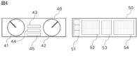
- FIG. 2 is a front view showing an example of a display on the first screen and the second screen of FIG. 1 .
- 5 is a front view showing an example of a display when a first switch is operated in FIG. 4.
- FIG. 5 is a front view showing an example of a display when a second switch is operated in FIG. 4.
- FIG. 7 is a front view showing an example of a display when a second switch is operated in FIG. 6;
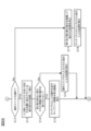
- FIG. 4 is a flowchart showing an example of a processing procedure in the vehicle display device of FIG. 3 (part 1);
- 4 is a flowchart showing an example of a processing procedure in the vehicle display device of FIG. 3
- the driver's seat of the vehicle is assumed to be installed on the left side of the vehicle. If the driver's seat is installed on the right side of the vehicle, the right and left in the following description will be interpreted as being symmetrical. In the following description, the vehicle occupants, including the driver, will also be referred to as users.
- FIG. 1 is a front view showing an example of a vehicle equipped with a vehicle display device according to the present invention, showing the arrangement of each device when the front of the vehicle is viewed from the driver's seat.
- An instrument panel 10 and a steering wheel 20 are arranged in front of the driver's seat, and a center console 30 is arranged between the driver's seat and the passenger seat.
- the instrument panel 10 includes a first screen 40 and a second screen 50
- the second screen 50 includes a touch panel 60 that inputs a touch operation by a user's finger touch or a stylus pen on the second screen 50.
- the touch panel 60 is arranged on the second screen 50, and constitutes a touch screen together with the second screen 50.
- the first screen 40 and the second screen 50 are, for example, liquid crystal displays, and may include speakers as output devices.
- the first screen 40 is disposed in front of the driver's seat, and the second screen 50 is disposed alongside the first screen 40 in the width direction of the vehicle.
- the location of the second screen 50 is not particularly limited as long as it is within a range where the driver can view the information displayed on the second screen 50, and examples include the central part of the instrument panel 10 in the vehicle width direction, or in front of the passenger seat.
- the first screen 40 and the second screen 50 may also be disposed adjacent to each other.
- the size of the first screen 40 and the second screen 50 is not particularly limited as long as it is within a range that allows the user to operate it appropriately, for example, 10 to 15 inches.
- the first screen 40 and the second screen 50 are not particularly limited as long as they are display devices that present information to the user, and may be a projector such as a head-up display.
- the steering wheel 20 is equipped with steering switches 21 and 22 that input commands to in-vehicle devices, etc.
- the steering switch 21 is located in a position where the driver can operate it with his/her left hand while holding the steering wheel 20, and the steering switch 22 is located in a position where the driver can operate it with his/her right hand while holding the steering wheel 20.
- FIG. 2 is a front view showing an example of the steering switches 21, 22 provided on the steering wheel 20.
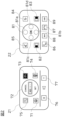
- the right-side steering switch 22 includes an operation switch 81, a first switch 82, and a second switch 83.
- the operation switch 81 is a switch through which the driver inputs operations for the first screen 40 and the second screen 50, and is, for example, a button switch, a toggle switch, a capacitance switch, or a combination of these. As shown in FIG. 2, the operation switch 81 is disposed between the first switch 82 and the second switch 83.
- the operation switch 81 also has a direction input unit through which the driver inputs an arbitrary direction in order to select information to be operated on the first screen 40 by the operation switch 81 (hereinafter also referred to as the first operation) from the information displayed on the first screen 40, and to select information to be operated on the second screen 50 by the operation switch 81 (hereinafter also referred to as the second operation) from the information displayed on the second screen 50.
- the information to be operated refers to information whose contents displayed on the screen (specifically, at least one of the first screen 40 and the second screen 50) change due to a certain operation (for example, the first operation, the second operation, an operation by the touch panel 60, etc.).
- the operation switch 81 shown in FIG. 2 includes directional input units 81a to 81d.
- Each directional input unit is a capacitance switch, and when directional input unit 81a is operated, the controller 90 controls the display on the first screen 40 and the second screen 50 assuming that an upward direction has been input.
- the controller 90 controls the display assuming that a downward direction has been input
- the controller 90 controls the display assuming that a left direction has been input
- directional input unit 81d when directional input unit 81d is operated, the controller 90 controls the display assuming that a right direction has been input.
- the first switch 82 and the second switch 83 are switches that respectively enable the driver to operate the first screen 40 and the second screen 50 by the operation switch 81 (i.e., enable operation of the first screen 40 and the second screen 50 by the operation switch 81).
- the first switch 82 and the second switch 83 are physical switches such as button switches and toggle switches.
- the arrangement of the first switch 82 and the second switch 83 corresponds to the arrangement of the first screen 40 and the second screen 50, so that it is intuitively understood which switch will enable operation input to which screen when operated.
- the first switch 82 and the second switch 83 are arranged so that the direction from the first switch 82 to the second switch 83 is the same as the direction from the first screen 40 to the second screen 50.
- the first switch 82 is arranged to the left of the second switch 83 as shown in FIG. 2.
- the direction from the first switch 82 to the second switch 83 and the direction from the first screen 40 to the second screen 50 are both to the right in the drawing.
- the first switch 82 will be located to the right of the second switch 83.
- the direction from the first switch 82 to the second switch 83 and the direction from the first screen 40 to the second screen 50 are both to the left.
- the operation switch 81, the first switch 82, and the second switch 83 may be arranged on the steering switch 22 of the steering wheel 20, or may be arranged on the center console 30 between the driver's seat and the passenger seat of the vehicle as shown in FIG. 1. In either case, the shape and size of each switch is appropriate within the range that allows the driver to operate them appropriately. Note that if the steering switch 22 is a touch screen equipped with a touch panel, the operation switch 81, the first switch 82, and the second switch 83 may be icons displayed on the steering switch 22.
- the first switch 82 may display a first icon that corresponds to the form of the first screen 40 and the second screen 50 and highlights the first screen 40.
- the second switch 83 may display a second icon that corresponds to the form of the first screen 40 and the second screen 50 and highlights the second screen 50.
- “Corresponding to the form of the first screen 40 and the second screen 50” means, for example, corresponding to the shape, arrangement, etc. of the first screen 40 and the second screen 50.
- “Highlighting the first screen 40 and the second screen 50” means, for example, making the part of the icon that corresponds to the first screen 40 or the second screen 50 a different color from the other parts, adding a display that highlights the part that corresponds to the first screen 40 or the second screen 50, etc.
- the first switch 82 and the second switch 83 are icons having two rectangles corresponding to the shapes of the first screen 40 and the second screen 50, and in the first icon of the first switch 82, the rectangle on the left side corresponding to the first screen 40 is black hatched, and in the second icon of the second switch 83, the rectangle on the right side corresponding to the second screen 50 is black hatched. If the first switch 82 and the second switch 83 are physical switches such as button switches, the first icon and the second icon shown in FIG. 2 are displayed on the first switch 82 and the second switch 83, respectively, and if the steering switch 22 is a touch screen, the first icon and the second icon shown in FIG. 2 are displayed on the steering switch 22.
- the steering switch 22 includes switches 84 to 89 in addition to the above-mentioned operation switch 81, first switch 82, and second switch 83.
- Switch 84 is a switch that cancels an input operation
- switch 85 is a switch that activates a voice input function using voice recognition.
- Switch 86 is a switch that activates a telephone function
- switch 87 is a switch that terminates the telephone function.
- Switches 88 and 89 are switches that are used for operations such as changing the song being played when the music player is activated.
- the left steering switch 21 includes switches 71 to 77.
- Switch 71 is a switch that activates autonomous driving control
- switch 72 is a switch that adjusts the vehicle speed and following distance while autonomous driving control is being executed.
- Switch 73 is a switch that changes the set vehicle speed during constant speed driving control
- switch 74 is a switch that changes the following distance during following driving.
- Switch 75 is a switch that activates the lane change assistance function.
- Switches 76 and 77 are switches that adjust the speaker volume.
- the steering switches 21, 22 shown in FIG. 2 have a function of displaying the switches 71-77, the operation switch 81, the first switch 82, the second switch 83, and the switches 84-89 in any color by using a backlight of any color.
- the steering switches 21, 22 including the operation switch 81, the first switch 82, and the second switch 83 can only be operated by the driver.
- the touch panel 60 can be operated by passengers other than the driver.
- FIG. 3 is a block diagram showing an example of an embodiment of the vehicle display device 1 according to the present invention.
- the vehicle display device 1 is a system consisting of the operation switch 81, first switch 82, second switch 83, touch panel 60, first screen 40, and second screen 50, which are among the devices shown in FIGS. 1 and 2.
- the controller 90 acquires instructions and information input from the operation switch 81, first switch 82, second switch 83, and touch panel 60, and controls the display of the first screen 40 and second screen 50 based on the acquired instructions and information.
- the controller 90 may include a first controller 91 that controls the display of the first screen 40 and the second screen 50 according to instructions output from the operation switch 81, and a second controller 92 different from the first controller 91 that controls the display of the first screen 40 and the second screen 50 according to instructions output from the first switch 82 and the second switch 83.
- the controller 90 is a device that controls each device that constitutes the vehicle display device 1 to make them work together and present information to the user.
- the controller 90 is, for example, a computer, and includes a CPU (Central Processing Unit) which is a processor, a ROM (Read Only Memory) in which programs are stored, and a RAM (Random Access Memory) which functions as an accessible storage device.
- the CPU is an operating circuit that executes the programs stored in the ROM and realizes the display function of the controller 90.
- the display function of the controller 90 allows the user to easily understand which screen changes in response to an operation when the controller 90 controls the display of the first screen 40 and the second screen 50.
- the ROM of the controller 90 stores a program for implementing the display function, and the CPU executes the program stored in the ROM to implement the display function.
- the display function is explained below with reference to Figures 4 to 7.
- Controller display function 4 is a front view showing an example of information displayed on the first screen 40 and the second screen 50.
- the display portion 41 of the first screen 40 shows information on the vehicle's traveling speed
- the display portion 42 shows information on the engine RPM.
- the display portions 43, 44, and 45 show items of information displayed between the display portion 41 and the display portion 42. Examples of information displayed between the display portion 41 and the display portion 42 include information on autonomous driving control, information on audio equipment, information on route guidance, information on the vehicle's traveling state, and warning information on the vehicle's state and the traveling environment.
- the display portion 51 of the second screen 50 shows menu icons indicating candidates for information to be displayed on the second screen 50.
- the menu icons are displayed at a predetermined position on the second screen 50, and unlike other display portions, the display position does not change due to user operation, and is always displayed in the same position while the second screen 50 is operating (power is ON).
- the predetermined position may be, for example, the left edge of the second screen 50 as shown in FIG. 4, or the lower side of the second screen 50 (particularly the lower center of the screen).
- the menu icons shown in FIG. 4 are divided into three sections, and in each section, an icon indicating a candidate for information to be displayed on the second screen 50 is displayed.
- Display areas 52, 53, and 54 respectively show map information with the driving route superimposed, route guidance information showing the vehicle's travel direction, and information related to audio equipment.
- the information displayed on second screen 50 is not limited to these, and in addition to menu icons, information related to telephone functions using a mobile device, information related to concierge services using AI, information related to the vehicle's driving status, time information, information related to the vehicle's battery, information related to game apps, and the like can be displayed on second screen 50.
- the controller 90 highlights the display portion of the first screen 40 that displays information on the operation target of the first operation by the operation switch 81 (hereinafter also referred to as the first display portion).
- the controller 90 highlights the display portion of the second screen 50 that displays information on the operation target of the second operation by the operation switch 81 (hereinafter also referred to as the second display portion).
- the information that is the target of a first operation refers to information whose content displayed on the first screen 40 changes due to a first operation
- the information that is the target of a second operation refers to information whose content displayed on the second screen 50 changes due to a second operation.
- displaying the first display part and the second display part in an emphasized manner refers to making part of the display part a different color from the other parts (for example, a color that is the opposite of the color surrounding the display part), adding a display to part of the display part that emphasizes that part, etc.
- the controller 90 when the controller 90 highlights the first display portion, it displays a first frame around the first display portion having a shape corresponding to that of the first display portion, and when the controller 90 highlights the second display portion, it displays a second frame around the second display portion having a shape corresponding to that of the second display portion.
- the colors of the first frame and the second frame are each set to a color (e.g., yellow) different from the color of the surroundings of the first display portion and the second display portion.
- the colors of the first switch 82 and the second switch 83 may be set to the same color as the colors of the first frame and the second frame, respectively.
- the first switch 82 causes the controller 90 to enable operation on the first screen 40 using the operation switch 81.
- the information displayed on the display portion 43 is set as the operation target of the first operation, and as shown in FIG. 5, a frame having a shape corresponding to the shape of the display portion 43 is displayed around the display portion 43, which is the first display portion.
- the information displayed on the display portion 43 is set as the operation target of the first operation in the case shown in FIG. 5, other information displayed on the first screen 40 may also be set as the operation target.
- the controller 90 When the controller 90 is highlighting the first display portion, if the second switch 83 is operated, the controller 90 highlights the menu icon displayed on the second screen 50. For example, when the information shown in FIG. 5 is displayed on the first screen 40 and the second screen 50, if the second switch 83 is operated, the controller 90 enables operation on the second screen 50 by the operation switch 81. Then, the controller 90 sets the information (icon) corresponding to the section 51a above the menu icon displayed on the display portion 51 as the operation target of the second operation, and displays a frame having a shape corresponding to the shape of the section 51a around the section 51a, which is the second display portion, as shown in FIG. 6. Note that, although the information displayed in the section 51a of the display portion 51 is set as the operation target of the second operation in the case shown in FIG. 6, information in other sections of the display portion 51 may be set as the operation target.
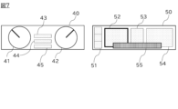
- the controller 90 When the controller 90 is highlighting the menu icons displayed on the second screen 50, if the second switch 83 is operated, the controller 90 highlights the display portions of the second screen 50 other than the menu icons. For example, when the information shown in FIG. 6 is displayed on the first screen 40 and the second screen 50, operating the second switch 83 causes the controller 90 to set the information displayed on the display portion 52 as the operation target of the second operation, and display a frame having a shape corresponding to the shape of the display portion 52 around the second display portion, as shown in FIG. 7. Note that, although the information displayed on the display portion 52 is set as the operation target of the second operation in the case shown in FIG. 7, other information displayed on the second screen 50 may also be set as the operation target.
- the controller 90 When the controller 90 is highlighting the display portion of the second screen 50 other than the menu icon, and the second switch 83 is operated, the controller 90 highlights the menu icon. For example, when the information shown in FIG. 7 is displayed on the first screen 40 and the second screen 50, operating the second switch 83 causes the controller 90 to set the information (icon) corresponding to the section 51a above the menu icon displayed on the display portion 51 as the operation target for the second operation, and displays a frame having a shape corresponding to the shape of section 51a around section 51a, which is the second display portion, as shown in FIG. 6.
- the controller 90 When the controller 90 is highlighting the second display portion, and the first switch 82 is operated, the controller 90 highlights one of the display portions of the first screen 40. For example, when the information shown in FIG. 6 is displayed on the first screen 40 and the second screen 50, operating the first switch 82 causes the controller 90 to enable operation on the first screen 40 using the operation switch 81. The controller 90 then sets the information displayed on the display portion 43 as the operation target of the first operation, and displays a frame having a shape corresponding to the shape of the display portion 43 around the first display portion, the display portion 43, as shown in FIG. 5.
- the controller 90 When a direction is input to the direction input unit of the operation switch 81 to select information to be operated from information displayed on the first screen 40 and the second screen 50, the controller 90 highlights the display portion displayed at a position corresponding to the input direction among the display portions around the first display portion or the second display portion currently highlighted and displayed. For example, when the information shown in FIG. 5 is displayed on the first screen 40 and the second screen 50, and the direction input unit 81b shown in FIG. 2 is operated, the controller 90 displays a frame having a shape corresponding to the shape of the display portion 44 around the display portion 44 shown in FIG. 5. When the information shown in FIG. 7 is displayed on the first screen 40 and the second screen 50, and the direction input unit 81d shown in FIG. 2 is operated, the controller 90 displays a frame having a shape corresponding to the shape of the display portion 53 around the display portion 53 shown in FIG. 7.
- the first display portion is one of the display portions of the first screen 40
- the second display portion is one of the display portions of the second screen 50
- the controller 90 highlights either the first display portion or the second display portion.
- first display portion is one of the display portions of the first screen 40
- second display portion is one of the display portions of the second screen 50
- the controller 90 highlights either the first display portion or the second display portion.
- multiple display portions of the first screen 40 may be highlighted as the first display portion
- multiple display portions of the second screen 50 may be highlighted as the second display portion.
- the controller 90 may stop the process of highlighting the first and second display parts when a touch operation is input to the touch panel 60. This is because, when a touch operation is input, the user can easily understand which screen the operation is being input to. As an example, when the display part 43 of the first screen 40 is highlighted as shown in FIG. 5, if a touch operation is input to the touch panel 60, the controller 90 stops the process of highlighting the display part 43. Then, the display of the first screen 40 becomes the display shown in FIG. 4. In addition, the controller 90 may stop the process of highlighting the first and second display parts when the first switch 82 and the second switch 83 are not operated for a predetermined time or more. This is because, if a state in which the driver does not input an operation continues for a predetermined time or more (for example, 5 to 30 seconds), it is assumed that the driver will not input a new operation.
- a predetermined time or more for example, 5 to 30 seconds
- the above-mentioned stopping of the process may be switched between enabled and disabled by the user.
- the controller 90 has a function to stop the process of highlighting the first and second display parts when the first and second switches 82 and 83 have not been operated for a predetermined time or longer, and when this function is enabled, the process of highlighting the display parts is stopped when the first and second switches have not been operated for a predetermined time or longer.
- this function is disabled, the process of highlighting the display parts continues even if the first and second switches have not been operated for a predetermined time or longer.
- the controller 90 may highlight the display portion showing the information that was displayed in the first display portion or the second display portion. This is because if a display portion showing information different from the information that was highlighted when the process was stopped is highlighted, the user will feel uncomfortable.
- the controller 90 may store the information displayed in the first display portion or the second display portion when the vehicle engine is stopped, and when the engine is started after the engine is stopped, the display portion showing the stored information will be highlighted. This is because if a display portion showing information different from the information that was highlighted when the engine was stopped is highlighted, the user will feel uncomfortable.
- the controller 90 may set in advance some of the information displayed on the second screen 50 not to accept the second operation by the operation switch 81 but to accept an operation input from the touch panel 60, and when the second operation is input, if the information displayed on the second display portion is set not to accept the second operation, a pop-up image may be displayed to prompt the driver to operate the information on the touch panel 60. For example, if the information displayed on the display portion 52 is set in advance not to accept the second operation by the operation switch 81, when a second operation on the information displayed on the display portion 52 is detected, the controller 90 displays a pop-up image 55 at the bottom center of the second screen 50.
- the controller 90 presets, among the information displayed on the second screen, information that the driver checks while driving at a frequency below a predetermined value as information that does not accept a second operation via the operation switch 81, and presets information that the driver checks while driving at a frequency higher than the predetermined value as information that accepts a second operation via the operation switch 81.
- the predetermined value can be set to an appropriate value within a range in which the driver does not feel uncomfortable about not being able to operate the operation switch 81 while driving, and is set so that, for example, information that the driver checks more than twice from the current position to the destination can be set as information that accepts a second operation.
- Information that the driver checks more than twice from the current position to the destination includes, for example, map information, route guidance information, information related to audio equipment, information related to the vehicle's driving status, time information, and information related to the vehicle's battery.
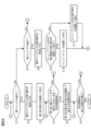
- FIGS. 8A and 8B are an example of a flowchart showing information processing in the vehicle display device 1 of this embodiment. The processing described below is executed by a processor (CPU) included in the controller 90 when some operation is performed on the vehicle display device 1.
- CPU central processing unit
- step S1 of FIG. 8A it is determined whether or not the driver has operated the first switch 82. If it is determined that the driver has operated the first switch 82, the process proceeds to step S2, where the first operation by the operation switch 81 is enabled, and in the subsequent step S3, the first display portion that displays information on the target of the first operation is highlighted, and the process proceeds to step S4.
- step S7 it is determined whether or not the driver has operated the second switch 83. If it is determined that the driver has operated the second switch 83, the process proceeds to step S8, where the second operation by the operation switch 81 is enabled, and in the subsequent step S9, it is determined whether or not the display portion of the second screen other than the menu icons is being highlighted.
- step S10 where the menu icon is highlighted
- step S4 If it is determined that the display portion of the second screen is not highlighted, the process also proceeds to step S10. On the other hand, if it is determined that the menu icon is highlighted, the process proceeds to step S11, where the display portion of the second screen other than the menu icon is highlighted, and the process proceeds to step S4.
- step S4 it is determined whether a predetermined time has passed without the first switch 82 and the second switch 83 being operated. If it is determined that the first switch 82 or the second switch 83 has been operated within the predetermined time, the process proceeds to step S1. In contrast, if it is determined that the predetermined time has passed without the first switch 82 and the second switch 83 being operated, the process proceeds to step S5, and the process of highlighting and displaying the first display portion and the second display portion is stopped.
- step S6 it is determined whether or not a new operation has been detected within the specified time. If it is determined that a new operation has been detected within the specified time, the process proceeds to step S1. In contrast, if it is determined that a new operation has not been detected within the specified time, execution of the routine is terminated.
- step S7 if it is determined in step S7 that the driver has not operated the second switch 83, the process proceeds to step S12 in FIG. 8B, where it is determined whether or not the driver has operated the operation switch 81. If it is determined that the driver has operated the operation switch 81, the process proceeds to step S13, where the display portion displayed at the position corresponding to the direction input to the direction input unit is highlighted. Furthermore, if a second operation has been input, it is determined in step S14 whether or not the information displayed in the second display portion has been preset so as not to accept the second operation.
- step S15 a pop-up image 55 prompting operation via the touch panel 60 is displayed on the second screen 50.
- step S16 processing is performed according to the instruction input from the operation switch 81. Then, the process proceeds to step S6 in FIG. 8A.
- step S17 where it is assumed that an operation has been input to the touch panel 60, and the process of highlighting and displaying the first and second display portions is stopped.
- step S18 the process is executed according to the instruction input from the touch panel 60. After that, the process proceeds to step S6 in FIG. 8A.
- the display device in the vehicular display method executed by the display device of the vehicle, includes a first screen 40 arranged in front of a driver's seat, a second screen 50 arranged alongside the first screen 40 in the width direction of the vehicle, an operation switch 81 through which a driver of the vehicle inputs operations on the first screen 40 and the second screen 50, a first switch 82 that enables a first operation on the first screen 40 by the operation switch 81, a second switch 83 that enables a second operation on the second screen 50 by the operation switch 81, and a controller 90 that controls display of the first screen 40 and the second screen 50.
- the operation switch 81 is disposed between the first switch 82 and the second switch 83, the direction from the first switch 82 to the second switch 83 is the same as the direction from the first screen 40 to the second screen 50, and when the first switch 82 is operated, the controller 90 highlights a first display portion of the display portion of the first screen 40 that displays information of an operation target of the first operation, and when the second switch 83 is operated, the controller 90 highlights a second display portion of the display portion of the second screen 50 that displays information of an operation target of the second operation. This makes it easy to grasp which screen changes its display depending on the operation when the display device has a plurality of screens.
- the controller 90 displays a menu icon indicating candidates for information to be displayed on the second screen 50 at a predetermined position on the second screen 50, and when the first display portion is displayed in an emphasized manner, when the second switch 83 is operated, the menu icon is displayed in an emphasized manner. This allows the driver to immediately select information to be displayed on the second screen 50.
- the controller 90 when the controller 90 is displaying the menu icon in an emphasized manner, if the second switch 83 is operated, the controller 90 displays the display portion of the second screen 50 other than the menu icon in an emphasized manner, and when the controller 90 is displaying the display portion of the second screen 50 other than the menu icon in an emphasized manner, if the second switch 83 is operated, the controller 90 displays the menu icon in an emphasized manner. This makes it possible to switch between the menu icon and the display portion other than the menu icon without using the operation switch 81.
- the controller 90 when the controller 90 is highlighting the second display portion, if the first switch 82 is operated, it highlights one of the display portions of the first screen 40. This makes it easy to grasp which screens change display depending on the operation.
- the operation switch 81 has direction input units 81a to 81d that input any direction so that the driver can select information to be operated in the first operation from the information displayed on the first screen 40 and select information to be operated in the second operation from the information displayed on the second screen 50, and when the direction is input to the direction input units 81a to 81d, the controller 90 highlights the display portion displayed in the position corresponding to the input direction among the display portions around the first display portion or the second display portion. This makes it possible to accurately highlight and display the display portion of the information selected by the driver as the operation target.
- the display device includes a touch panel 60 for inputting a touch operation to the second screen 50, and the controller 90 stops the process of highlighting the first display portion and the second display portion when the touch operation is input to the touch panel 60. This makes it possible to stop unnecessary processing of highlighting display portions when the user can easily determine which screen the operation is being input to.
- the controller 90 stops the process of highlighting the first display portion and the second display portion. This makes it possible to stop unnecessary processing of highlighting the display portions when it is estimated that the driver will not input a new operation.
- the controller 90 has a function of stopping the process of highlighting the first display portion and the second display portion when the first switch 82 and the second switch 83 have not been operated for a predetermined time or longer, and when the function is enabled, stops the process when the first switch 82 and the second switch 83 have not been operated for the predetermined time or longer. This makes it possible to stop unnecessary processing of highlighting the display portions when it is estimated that the driver will not input a new operation.
- the controller 90 highlights the display portion that displays the information that was displayed in the first display portion or the second display portion. This makes it possible to suppress the sense of discomfort felt by the user by highlighting the display portion that displays information different from the information that was highlighted when the processing was stopped.
- the controller 90 stores the information displayed on the first display portion or the second display portion when the engine of the vehicle is stopped, and when the engine is started after the engine is stopped, the display portion showing the stored information is highlighted. This makes it possible to reduce the sense of discomfort felt by the user when the display portion showing information different from the information that was highlighted when the engine was stopped is highlighted.
- the controller 90 when the first display portion is to be displayed with emphasis, the controller 90 displays a first frame around the first display portion, and when the second display portion is to be displayed with emphasis, the controller 90 displays a second frame around the second display portion, and sets the color of the first switch 82 and the color of the second switch 83 to the same color as the color of the first frame and the color of the second frame, respectively. This makes it possible to more reliably highlight the display portion and to more easily grasp the screen whose display changes in response to operation.
- the controller 90 displays, on the first switch 82, a first icon that corresponds to the form of the first screen 40 and the second screen 50 and highlights the first screen 40, and displays, on the second switch 83, a second icon that corresponds to the form and highlights the second screen 50. This makes it easier to grasp the screens whose display changes depending on the operation.
- the operation switch 81, the first switch 82, and the second switch 83 are provided on the steering wheel 20 of the vehicle or on the center console 30 between the driver's seat and the passenger seat. This makes it easier for the driver to operate the switches.
- the display device includes a touch panel 60 for inputting a touch operation to the second screen 50, and the controller 90 pre-sets a portion of the information displayed on the second screen 50 to not accept the second operation but to accept an operation input from the touch panel 60, and when the second operation is input, if the information displayed on the second display portion is set not to accept the second operation, a pop-up image 55 is displayed on the second screen 50 to prompt the driver to operate the touch panel 60. This allows the driver to recognize more quickly that an operation using the touch panel 60 is required.
- the controller 90 pre-sets, among the information displayed on the second screen 50, information that the driver checks more frequently while driving than a predetermined value as information that accepts the second operation. This makes it possible to operate the information that the driver frequently checks while driving using the operation switch 81 while driving.
- the first display portion is one of the display portions of the first screen 40
- the second display portion is one of the display portions of the second screen 50
- the controller 90 highlights and displays one of the first display portion and the second display portion. This makes it possible to highlight the display portions more reliably.
- the controller 90 includes a first controller 91 that controls the display of the first screen 40 and the second screen 50 according to instructions output from the operation switch 81, and a second controller 92 different from the first controller 91 that controls the display of the first screen 40 and the second screen 50 according to instructions output from the first switch 82 and the second switch 83.
- a controller suitable for processing each switch is possible to use.
- the controller 90 when the controller 90 is to highlight the first display portion, it displays a first frame having a shape corresponding to the shape of the first display portion around the first display portion, and when the controller 90 is to highlight the second display portion, it displays a second frame having a shape corresponding to the shape of the second display portion around the second display portion. This makes it possible to highlight the display portions more reliably.
- the vehicle includes a first screen 40 arranged in front of the driver's seat of the vehicle, a second screen 50 arranged alongside the first screen 40 in the width direction of the vehicle, an operation switch 81 through which the driver of the vehicle inputs operations on the first screen 40 and the second screen 50, a first switch 82 that enables a first operation on the first screen 40 by the operation switch 81, a second switch 83 that enables a second operation on the second screen 50 by the operation switch 81, and a controller 90 that controls the display of the first screen 40 and the second screen 50, and the operation switch 81 is
- the vehicle display device 1 is provided in such a manner that, when the first switch 82 is operated, the controller 90 highlights a first display portion of the display portion of the first screen 40 that displays information on the operation target of the first operation, and when the second switch 83 is operated, the controller 90 highlights a second display portion of the display portion of the second screen 50 that displays information on the operation target of the second operation.
Landscapes
- Engineering & Computer Science (AREA)
- Chemical & Material Sciences (AREA)
- Combustion & Propulsion (AREA)
- Transportation (AREA)
- Mechanical Engineering (AREA)
- Fittings On The Vehicle Exterior For Carrying Loads, And Devices For Holding Or Mounting Articles (AREA)
Priority Applications (4)
| Application Number | Priority Date | Filing Date | Title |
|---|---|---|---|
| PCT/JP2023/004739 WO2024171242A1 (ja) | 2023-02-13 | 2023-02-13 | 車両用表示方法及び車両用表示装置 |
| JP2025500424A JPWO2024171242A1 (https=) | 2023-02-13 | 2023-02-13 | |
| EP23922583.2A EP4667265A4 (en) | 2023-02-13 | 2023-02-13 | AUTOMOTIVE DISPLAY METHOD AND AUTOMOTIVE DISPLAY DEVICE |
| CN202380093745.4A CN120615064A (zh) | 2023-02-13 | 2023-02-13 | 车辆用显示方法和车辆用显示装置 |
Applications Claiming Priority (1)
| Application Number | Priority Date | Filing Date | Title |
|---|---|---|---|
| PCT/JP2023/004739 WO2024171242A1 (ja) | 2023-02-13 | 2023-02-13 | 車両用表示方法及び車両用表示装置 |
Publications (1)
| Publication Number | Publication Date |
|---|---|
| WO2024171242A1 true WO2024171242A1 (ja) | 2024-08-22 |
Family
ID=92420901
Family Applications (1)
| Application Number | Title | Priority Date | Filing Date |
|---|---|---|---|
| PCT/JP2023/004739 Ceased WO2024171242A1 (ja) | 2023-02-13 | 2023-02-13 | 車両用表示方法及び車両用表示装置 |
Country Status (4)
| Country | Link |
|---|---|
| EP (1) | EP4667265A4 (https=) |
| JP (1) | JPWO2024171242A1 (https=) |
| CN (1) | CN120615064A (https=) |
| WO (1) | WO2024171242A1 (https=) |
Citations (5)
| Publication number | Priority date | Publication date | Assignee | Title |
|---|---|---|---|---|
| JP2007153194A (ja) * | 2005-12-07 | 2007-06-21 | Mazda Motor Corp | 車両用情報表示装置 |
| JP2013120447A (ja) * | 2011-12-06 | 2013-06-17 | Nippon Soken Inc | 表示制御システム |
| JP2013121804A (ja) * | 2011-12-12 | 2013-06-20 | Fujitsu Ten Ltd | 車載表示システム |
| JP2016147665A (ja) * | 2016-03-02 | 2016-08-18 | トヨタ自動車株式会社 | 車両用情報表示装置 |
| WO2019225305A1 (ja) | 2018-05-25 | 2019-11-28 | 株式会社デンソー | 車両用表示制御システム、車両用表示制御プログラム及び記憶媒体 |
Family Cites Families (3)
| Publication number | Priority date | Publication date | Assignee | Title |
|---|---|---|---|---|
| KR20170089328A (ko) * | 2016-01-26 | 2017-08-03 | 삼성전자주식회사 | 자동차 제어 시스템과 그의 운영 방법 |
| JP2021075157A (ja) * | 2019-11-08 | 2021-05-20 | トヨタ自動車株式会社 | 車両用入力装置 |
| US11620006B2 (en) * | 2020-07-07 | 2023-04-04 | Hyundai Mobis Co., Ltd. | Display control system using knob |
-
2023
- 2023-02-13 WO PCT/JP2023/004739 patent/WO2024171242A1/ja not_active Ceased
- 2023-02-13 CN CN202380093745.4A patent/CN120615064A/zh active Pending
- 2023-02-13 EP EP23922583.2A patent/EP4667265A4/en active Pending
- 2023-02-13 JP JP2025500424A patent/JPWO2024171242A1/ja active Pending
Patent Citations (5)
| Publication number | Priority date | Publication date | Assignee | Title |
|---|---|---|---|---|
| JP2007153194A (ja) * | 2005-12-07 | 2007-06-21 | Mazda Motor Corp | 車両用情報表示装置 |
| JP2013120447A (ja) * | 2011-12-06 | 2013-06-17 | Nippon Soken Inc | 表示制御システム |
| JP2013121804A (ja) * | 2011-12-12 | 2013-06-20 | Fujitsu Ten Ltd | 車載表示システム |
| JP2016147665A (ja) * | 2016-03-02 | 2016-08-18 | トヨタ自動車株式会社 | 車両用情報表示装置 |
| WO2019225305A1 (ja) | 2018-05-25 | 2019-11-28 | 株式会社デンソー | 車両用表示制御システム、車両用表示制御プログラム及び記憶媒体 |
Non-Patent Citations (1)
| Title |
|---|
| See also references of EP4667265A4 |
Also Published As
| Publication number | Publication date |
|---|---|
| CN120615064A (zh) | 2025-09-09 |
| EP4667265A1 (en) | 2025-12-24 |
| JPWO2024171242A1 (https=) | 2024-08-22 |
| EP4667265A4 (en) | 2026-04-08 |
Similar Documents
| Publication | Publication Date | Title |
|---|---|---|
| KR101613407B1 (ko) | 지원 기능을 갖춘 차량 시스템 및 차량 시스템 작동 방법 | |
| JP4260383B2 (ja) | 車載用表示装置 | |
| JP4631957B2 (ja) | ナビゲーション装置 | |
| JP5136947B2 (ja) | 車両用操作装置 | |
| US10967737B2 (en) | Input device for vehicle and input method | |
| JP2013096736A (ja) | 車両用表示装置 | |
| JP5534161B2 (ja) | ユーザインタフェース装置 | |
| JP6406088B2 (ja) | 操作システム | |
| JP2007310496A (ja) | タッチ操作入力装置 | |
| JP2016184238A (ja) | 操作システム | |
| JP2008195142A (ja) | 車載機器の操作支援装置、操作支援方法 | |
| US20210129673A1 (en) | Input device | |
| KR20150055680A (ko) | 차량용 블라인드 콘트롤 시스템 | |
| JP2006264615A (ja) | 車両用表示装置 | |
| JP2008039731A (ja) | ナビゲーション装置およびその画面表示方法 | |
| WO2024171242A1 (ja) | 車両用表示方法及び車両用表示装置 | |
| JP2012096670A (ja) | 入力装置及び入力方法 | |
| JP2016006601A (ja) | 視線入力装置 | |
| JP7120047B2 (ja) | 入力装置 | |
| JP7240895B2 (ja) | 表示装置、および、表示制御方法 | |
| JP2009162691A (ja) | 車載情報端末 | |
| JP5125977B2 (ja) | 入力支援装置 | |
| US12472824B2 (en) | Display device for vehicles and display method for vehicles | |
| JP2009126366A (ja) | 車両用表示装置 | |
| US20240042856A1 (en) | Method for Operating a Digital Assistant of a Vehicle, Computer-Readable Medium, System, and Vehicle |
Legal Events
| Date | Code | Title | Description |
|---|---|---|---|
| 121 | Ep: the epo has been informed by wipo that ep was designated in this application |
Ref document number: 23922583 Country of ref document: EP Kind code of ref document: A1 |
|
| ENP | Entry into the national phase |
Ref document number: 2025500424 Country of ref document: JP Kind code of ref document: A |
|
| WWE | Wipo information: entry into national phase |
Ref document number: 2025500424 Country of ref document: JP |
|
| WWE | Wipo information: entry into national phase |
Ref document number: 202380093745.4 Country of ref document: CN |
|
| WWP | Wipo information: published in national office |
Ref document number: 202380093745.4 Country of ref document: CN |
|
| WWE | Wipo information: entry into national phase |
Ref document number: 2023922583 Country of ref document: EP |
|
| NENP | Non-entry into the national phase |
Ref country code: DE |
|
| ENP | Entry into the national phase |
Ref document number: 2023922583 Country of ref document: EP Effective date: 20250915 |
|
| WWP | Wipo information: published in national office |
Ref document number: 2023922583 Country of ref document: EP |