WO2024166518A1 - 液体材料気化装置、液体材料気化システム - Google Patents
液体材料気化装置、液体材料気化システム Download PDFInfo
- Publication number
- WO2024166518A1 WO2024166518A1 PCT/JP2023/044041 JP2023044041W WO2024166518A1 WO 2024166518 A1 WO2024166518 A1 WO 2024166518A1 JP 2023044041 W JP2023044041 W JP 2023044041W WO 2024166518 A1 WO2024166518 A1 WO 2024166518A1
- Authority
- WO
- WIPO (PCT)
- Prior art keywords
- liquid material
- heater
- wall
- container
- storage container
- Prior art date
- Legal status (The legal status is an assumption and is not a legal conclusion. Google has not performed a legal analysis and makes no representation as to the accuracy of the status listed.)
- Ceased
Links
Images



Classifications
-
- H—ELECTRICITY
- H10—SEMICONDUCTOR DEVICES; ELECTRIC SOLID-STATE DEVICES NOT OTHERWISE PROVIDED FOR
- H10P—GENERIC PROCESSES OR APPARATUS FOR THE MANUFACTURE OR TREATMENT OF DEVICES COVERED BY CLASS H10
- H10P72/00—Handling or holding of wafers, substrates or devices during manufacture or treatment thereof
- H10P72/04—Apparatus for manufacture or treatment
- H10P72/0402—Apparatus for fluid treatment
-
- B—PERFORMING OPERATIONS; TRANSPORTING
- B01—PHYSICAL OR CHEMICAL PROCESSES OR APPARATUS IN GENERAL
- B01J—CHEMICAL OR PHYSICAL PROCESSES, e.g. CATALYSIS OR COLLOID CHEMISTRY; THEIR RELEVANT APPARATUS
- B01J19/00—Chemical, physical or physico-chemical processes in general; Their relevant apparatus
- B01J19/0006—Controlling or regulating processes
- B01J19/0013—Controlling the temperature of the process
-
- B—PERFORMING OPERATIONS; TRANSPORTING
- B01—PHYSICAL OR CHEMICAL PROCESSES OR APPARATUS IN GENERAL
- B01J—CHEMICAL OR PHYSICAL PROCESSES, e.g. CATALYSIS OR COLLOID CHEMISTRY; THEIR RELEVANT APPARATUS
- B01J7/00—Apparatus for generating gases
- B01J7/02—Apparatus for generating gases by wet methods
-
- C—CHEMISTRY; METALLURGY
- C23—COATING METALLIC MATERIAL; COATING MATERIAL WITH METALLIC MATERIAL; CHEMICAL SURFACE TREATMENT; DIFFUSION TREATMENT OF METALLIC MATERIAL; COATING BY VACUUM EVAPORATION, BY SPUTTERING, BY ION IMPLANTATION OR BY CHEMICAL VAPOUR DEPOSITION, IN GENERAL; INHIBITING CORROSION OF METALLIC MATERIAL OR INCRUSTATION IN GENERAL
- C23C—COATING METALLIC MATERIAL; COATING MATERIAL WITH METALLIC MATERIAL; SURFACE TREATMENT OF METALLIC MATERIAL BY DIFFUSION INTO THE SURFACE, BY CHEMICAL CONVERSION OR SUBSTITUTION; COATING BY VACUUM EVAPORATION, BY SPUTTERING, BY ION IMPLANTATION OR BY CHEMICAL VAPOUR DEPOSITION, IN GENERAL
- C23C16/00—Chemical coating by decomposition of gaseous compounds, without leaving reaction products of surface material in the coating, i.e. chemical vapour deposition [CVD] processes
- C23C16/44—Chemical coating by decomposition of gaseous compounds, without leaving reaction products of surface material in the coating, i.e. chemical vapour deposition [CVD] processes characterised by the method of coating
- C23C16/448—Chemical coating by decomposition of gaseous compounds, without leaving reaction products of surface material in the coating, i.e. chemical vapour deposition [CVD] processes characterised by the method of coating characterised by the method used for generating reactive gas streams, e.g. by evaporation or sublimation of precursor materials
-
- C—CHEMISTRY; METALLURGY
- C23—COATING METALLIC MATERIAL; COATING MATERIAL WITH METALLIC MATERIAL; CHEMICAL SURFACE TREATMENT; DIFFUSION TREATMENT OF METALLIC MATERIAL; COATING BY VACUUM EVAPORATION, BY SPUTTERING, BY ION IMPLANTATION OR BY CHEMICAL VAPOUR DEPOSITION, IN GENERAL; INHIBITING CORROSION OF METALLIC MATERIAL OR INCRUSTATION IN GENERAL
- C23C—COATING METALLIC MATERIAL; COATING MATERIAL WITH METALLIC MATERIAL; SURFACE TREATMENT OF METALLIC MATERIAL BY DIFFUSION INTO THE SURFACE, BY CHEMICAL CONVERSION OR SUBSTITUTION; COATING BY VACUUM EVAPORATION, BY SPUTTERING, BY ION IMPLANTATION OR BY CHEMICAL VAPOUR DEPOSITION, IN GENERAL
- C23C16/00—Chemical coating by decomposition of gaseous compounds, without leaving reaction products of surface material in the coating, i.e. chemical vapour deposition [CVD] processes
- C23C16/44—Chemical coating by decomposition of gaseous compounds, without leaving reaction products of surface material in the coating, i.e. chemical vapour deposition [CVD] processes characterised by the method of coating
- C23C16/448—Chemical coating by decomposition of gaseous compounds, without leaving reaction products of surface material in the coating, i.e. chemical vapour deposition [CVD] processes characterised by the method of coating characterised by the method used for generating reactive gas streams, e.g. by evaporation or sublimation of precursor materials
- C23C16/4485—Chemical coating by decomposition of gaseous compounds, without leaving reaction products of surface material in the coating, i.e. chemical vapour deposition [CVD] processes characterised by the method of coating characterised by the method used for generating reactive gas streams, e.g. by evaporation or sublimation of precursor materials by evaporation without using carrier gas in contact with the source material
-
- H—ELECTRICITY
- H10—SEMICONDUCTOR DEVICES; ELECTRIC SOLID-STATE DEVICES NOT OTHERWISE PROVIDED FOR
- H10P—GENERIC PROCESSES OR APPARATUS FOR THE MANUFACTURE OR TREATMENT OF DEVICES COVERED BY CLASS H10
- H10P14/00—Formation of materials, e.g. in the shape of layers or pillars
- H10P14/20—Formation of materials, e.g. in the shape of layers or pillars of semiconductor materials
- H10P14/29—Formation of materials, e.g. in the shape of layers or pillars of semiconductor materials characterised by the substrates
-
- H—ELECTRICITY
- H10—SEMICONDUCTOR DEVICES; ELECTRIC SOLID-STATE DEVICES NOT OTHERWISE PROVIDED FOR
- H10P—GENERIC PROCESSES OR APPARATUS FOR THE MANUFACTURE OR TREATMENT OF DEVICES COVERED BY CLASS H10
- H10P14/00—Formation of materials, e.g. in the shape of layers or pillars
- H10P14/60—Formation of materials, e.g. in the shape of layers or pillars of insulating materials
-
- H—ELECTRICITY
- H10—SEMICONDUCTOR DEVICES; ELECTRIC SOLID-STATE DEVICES NOT OTHERWISE PROVIDED FOR
- H10P—GENERIC PROCESSES OR APPARATUS FOR THE MANUFACTURE OR TREATMENT OF DEVICES COVERED BY CLASS H10
- H10P72/00—Handling or holding of wafers, substrates or devices during manufacture or treatment thereof
- H10P72/04—Apparatus for manufacture or treatment
- H10P72/0431—Apparatus for thermal treatment
- H10P72/0432—Apparatus for thermal treatment mainly by conduction
Definitions
- the present invention relates to a liquid material vaporizer and liquid material vaporizer system that heats and vaporizes liquid materials.
- Patent Document 1 discloses such a liquid material vaporizer that includes a material tank that contains the liquid material, a heater that heats the liquid material in the material tank, an outlet pipe through which gas produced by vaporizing the liquid material in the material tank is discharged, and a liquid flow control device that controls the flow rate of the gas that flows through the outlet pipe.
- the heater is positioned so as to cover the entire sides and bottom of the material tank.
- Patent Document 2 also discloses a liquid material vaporizer that uses a different heater system. This system does not heat the container that holds the liquid material from the outside, but instead inserts a cartridge heater into the top wall of the container to bring it into contact with the liquid material, heating the liquid material from inside the container.
- the above-mentioned conventional liquid material vaporizers have a problem in that the heater is difficult to maintain.
- a rubber heater is used as the heater, and the rubber heater is wrapped around the entire side of the material tank to cover it, and then fixed with a metal plate, or the rubber heater is laid on the bottom of the tank, so that it is difficult to easily attach and detach the heater.
- a heater is provided so as to pass through the upper wall of a container, but an inlet pipe for introducing liquid material and an outlet pipe for discharging gas are usually also inserted through the upper wall of the liquid material vaporizer, and other components such as a liquid flow rate control device such as a mass flow controller are mounted on the upper surface of the liquid material vaporizer. Therefore, access to the upper surface of the liquid material vaporizer is poor, and since other components are mounted on the upper surface, it is difficult to pull out the heater from the upper surface.
- the present invention was made in consideration of the above problems, and its main objective is to provide a liquid material vaporizer with excellent maintainability, allowing easy replacement of the heater, etc.
- the liquid material vaporization device of the present invention is characterized in that it comprises a storage container having side walls and a bottom wall that form a storage space for storing liquid material, and a heater that heats and vaporizes the liquid material stored in the storage space, and that an insertion hole is formed in the side wall or the bottom wall that extends along the inner wall surface and opens to the outer surface of the storage container, and that the heater is inserted into the insertion hole.
- the heater since the heater is attached by inserting it into the side wall or bottom wall through an insertion hole that opens on the outer surface of the container, which does not have an inlet pipe or outlet pipe inserted therethrough and does not interfere with a liquid flow rate control device such as a mass flow controller, the heater can be easily attached and detached from the container as long as the outer surface of the container is accessible. This makes it easy to replace the heater, improving the maintainability of the liquid material vaporizer.
- the term “bottom wall” refers to a wall that covers the storage space from below when the storage container is in the correct usage state
- the term “side wall” refers to a wall that covers the storage space from the side (i.e., transversely) when the storage container is in the correct usage state.
- a specific embodiment in which the heater can be more easily attached and detached from the container is one in which the insertion hole of the liquid material vaporizer extends straight along the inner wall surface and the heater is columnar. With this type of heater, the heater can be easily attached and detached by simply inserting and removing the heater straight along the insertion hole.
- the liquid material vaporization device preferably contains a casing that contains the storage container in a predetermined orientation and has an opening formed in its side wall, and the insertion hole is preferably formed on the outer surface of the storage container contained within the casing, facing the opening of the casing.
- the first step would be to enlarge the tank to increase the amount of liquid material that can be stored in it, but most of the semiconductor manufacturing equipment that uses this gas is relatively small, and if the tank were made larger, it would be impossible to incorporate it into the semiconductor manufacturing equipment. Therefore, in order to generate a large amount of gas without making the tank larger, it is conceivable to increase the heating rate of the liquid material to generate a large amount of gas. However, when the heating rate of the liquid material is increased, another problem occurs in that the internal pressure of the tank fluctuates greatly when the phase transition from liquid to gas occurs.
- a grooved region is formed in the inner wall surface of the side wall or the bottom wall at a location closest to the heater.
- grooves are provided in the area of the inner wall surface of the bottom wall of the container that is most likely to be heated by the heater, so bubbles that become the nuclei of boiling can be easily generated in the recesses of the grooves, and bumping due to an overheating state where the container is heated above the boiling point can be prevented.
- bubbles generated in the recesses of the grooves can be desorbed more quickly than bubbles generated on a surface that is not grooved, so the size of the bubbles can be prevented from becoming large. This reduces the size of the bubbles that are generated when the phase transition from liquid to gas occurs, thereby reducing pressure fluctuations, thereby increasing the amount of gas generated without increasing the size of the storage container.
- a plurality of grooves are formed in the groove processing area in a lattice pattern, a twill pattern, a flat pattern, or a concentric circle pattern.
- the grooved region is partially formed on an inner wall surface of the side wall or the bottom wall. Rather than forming grooves on the entire inner wall surface of the bottom wall, grooves are formed only in areas near the inserted heater where boiling is likely to occur, thereby improving cost-effectiveness. Furthermore, when performing maintenance on the liquid material vaporizer, it is necessary to purge the container of liquid material to empty it, but if grooves are formed on the entire inner wall surface of the bottom wall, there is a risk that liquid will remain in the grooves. By forming grooves only in necessary parts of the inner wall surface of the bottom wall, it is possible to easily prevent liquid material from remaining during maintenance.
- the width of the groove processing area along a direction perpendicular to the insertion/removal direction of the heater is about 2.5 times or more and about 5 times or less than the width of the heater when viewed from above in a plan view.
- an overheat protection element is attached to the outer wall surface of the storage container, and when the heater becomes excessively hot, this overheat protection element cuts off the supply of power to the heater, thereby preventing overheating.
- the hottest part of the heater i.e., the inside of the container
- the overheat protection element is separated from the overheat protection element, resulting in poor heat transfer and a large discrepancy between the actual temperature of the heater and the temperature detected by the overheat protection element.
- the liquid material vaporization device is configured so that the storage container comprises a downwardly opening container body that constitutes the side wall, and a bottom plate member that covers the opening of the container body and constitutes the bottom wall, and further comprises an overheating prevention mechanism that prevents the heater from overheating, the overheating prevention mechanism being provided within the side wall, within the bottom wall, on the outer surface of the side wall or on the surface of the bottom plate member, and further comprises an overheating protection element that cuts off the supply of power to the heater when the heater becomes excessively hot.
- the liquid material vaporizing device further includes a flow rate adjusting section for adjusting the flow rate of the gas discharged from the storage vessel.
- a flow rate adjusting section for adjusting the flow rate of the gas discharged from the storage vessel.
- a liquid material vaporization system includes the liquid material vaporization device described above, and a liquid material supply device that supplies a liquid material to the liquid material vaporization device.
- a liquid material vaporization system can achieve the same effects as the liquid material vaporization device of the present invention.
- the present invention provides a liquid material vaporizer that is easy to maintain and allows for easy heater replacement.
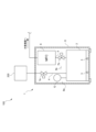
- FIG. 1 is a schematic diagram showing the configuration of a liquid material vaporizing device according to one embodiment of the present invention
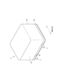
- FIG. 2 is a perspective view showing a schematic configuration of a storage container according to the embodiment.
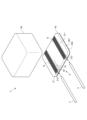
- FIG. 2 is an exploded perspective view showing a schematic configuration of a storage container according to the embodiment.
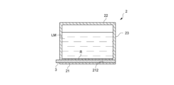
- 5A and 5B are cross-sectional views showing a schematic configuration of a storage container according to the embodiment, in which FIG. 5A shows a cross section perpendicular to a direction in which a heater is inserted and removed, and FIG. 5B shows a cross section along the direction in which a heater is inserted and removed.
- FIG. 13 is a perspective view showing a configuration of a bottom plate member of a storage container according to another embodiment.
- FIG. 13 is a perspective view showing a configuration of a bottom plate member of a storage container according to another embodiment.
- FIG. 13 is a perspective view showing a configuration of a bottom plate member of a storage container according to another embodiment.
- FIG. 13 is a perspective view showing a configuration of a bottom plate member of a storage container according to another embodiment.
- FIG. 13 is a perspective view showing a configuration of a bottom plate member of a storage container according to another embodiment.
- FIG. 13 is a perspective view showing a configuration of a bottom plate member of a storage container according to another embodiment.
- FIG. 11 is a cross-sectional view illustrating a configuration of a storage container according to another embodiment.
- FIG. 11 is a cross-sectional view illustrating a configuration of a storage container according to another embodiment.
- FIG. 13 is a perspective view illustrating a configuration of a storage container according to another embodiment.
- the liquid material vaporization system 100 of this embodiment vaporizes liquid material to generate gas for use in the manufacturing process of, for example, semiconductors, and sends this gas to the target device.
- This liquid material vaporization system 100 includes a liquid material supply device 200 that supplies liquid material, and a liquid material vaporization device 1 that vaporizes the liquid material supplied from the liquid material supply device 200 to generate gas.
- the liquid material vaporization device 1 will be described in detail below.
- this liquid material vaporization device 1 comprises a storage container 2 that stores liquid material LM, a heater 3 that heats and vaporizes the liquid material LM stored in the storage container 2, an inlet pipe 4 that supplies the liquid material LM to the storage container 2, an outlet pipe 5 that guides the gas resulting from the vaporization of the liquid material LM from the storage container 2 to the target device, a flow rate regulator 6 that adjusts the flow rate of the gas flowing through the outlet pipe 5, and a casing 8 that houses these components inside.
- the upstream end of the inlet pipe 4 is connected to a liquid material supply device 200 that supplies the liquid material LM.
- the storage container 2 has a generally rectangular parallelepiped shape with an internal storage space for storing the liquid material LM.
- the storage container 2 has a bottom wall 21, an upper wall 22, and a side wall 23, and the storage space is formed by these inner wall surfaces.
- the lower wall in the vertical direction is the bottom wall 21
- the upper wall is the upper wall 22, and the wall that intersects with the horizontal direction is the side wall 23.
- An inlet pipe 4, an outlet pipe 5, and a pressure gauge 12 for measuring the pressure inside the container are provided so as to penetrate the upper wall 22 of the storage container 2 (these components are omitted in each figure other than Figure 1).
- the storage container 2 of this embodiment has a container body 2a that opens downward and a bottom plate member 2b that closes the opening of the container body 2a.
- the container body 2a is watertightly attached to the upper surface of the bottom plate member 2b by welding or the like.
- the top wall 22 and side wall 23 of the storage container 2 are formed by the container body 2a, and the bottom wall 21 is formed by the bottom plate member 2b.
- the inlet pipe 4 and outlet pipe 5 are provided with on-off valves 7a and 7b, respectively.
- the flow rate adjustment unit 6 is composed of, for example, a mass flow controller, and this mass flow controller has a measurement unit that measures the flow rate of the gas flowing through the outlet pipe 5, and an opening/closing unit that opens and closes the line of the outlet pipe 5 so that the value measured by the measurement unit becomes a predetermined flow rate.
- This flow rate adjustment unit 6 is disposed above (for example, directly above) the storage vessel 2.
- the casing 8 has a roughly rectangular parallelepiped shape with a storage chamber 8s formed therein that contains at least the storage container 2 and the flow rate adjustment unit 6.
- An opening 8a is formed in one side wall of the casing 8 that forms the storage chamber 8s, and a user can access and operate the equipment stored in the storage chamber 8s through the opening 8a, as well as insert and remove the equipment.
- the casing 8 is configured to store the storage container 2 and the flow rate adjustment unit 6 in the storage chamber 8s in a predetermined orientation.
- the casing 8 may have an opening and closing door that closes the opening 8a.
- the heater 3 is attached by being inserted into the bottom wall 21 of the container 2 from its outer surface 2s (i.e., from the side).
- a linear insertion hole 212 is formed that extends straight along the inner wall surface (also called the bottom surface 211) of the bottom wall 21 that forms the storage space and opens from the outer surface 2s. "Extending along the inner wall surface” means that the insertion hole 212 extends in a direction that intersects with the wall thickness direction and is formed so as not to open on the inner wall surface, and includes not only those formed parallel to the inner wall surface but also those formed at an angle to the inner wall surface.
- the heater 3 is a cartridge heater that is columnar (specifically, approximately cylindrical), and is inserted straight into the insertion hole 212 formed in the bottom wall 21 so as to be insertable and removable. In this embodiment, a plurality of parallel insertion holes 212 are formed horizontally spaced apart in the bottom wall 21 of the storage container 2, and the heater 3 is inserted into each insertion hole 212.
- the insertion hole 212 is formed so as to open to the surface of the outer surface 2s of the storage container 2 housed in the casing 8, facing the opening 8a of the casing 8.
- the heater 3 is designed to be inserted and removed from the surface of the outer surface 2s of the storage container 2 housed in the casing 8, facing the opening 8a of the casing 8.
- the bottom plate member 2b in which the insertion hole 212 is formed is composed of multiple plate materials stacked in the thickness direction.
- the bottom plate member 2b has an inner wall surface that forms a storage space on one face plate, and is equipped with a bottom plate body 2b1 in which a U-shaped groove is formed on the other face plate (i.e., the back side), and a cover plate 2b2 provided on the back side of the bottom plate body 2b1 to close the U-shaped groove.
- This U-shaped groove is formed straight along the inner wall surface of the bottom plate body 2b1, and the insertion hole 212 is formed by closing the U-shaped groove of this bottom plate body 2b1 with the cover plate 2b2.
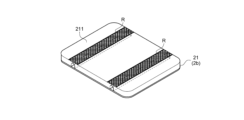
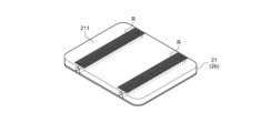
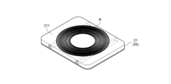
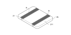
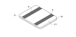
- a grooved region R is formed on the bottom surface 211 of the storage container 2 in a location closest to the inserted heater 3 (i.e., directly above the heater 3) where grooves are machined.
- This grooved region R is an area where multiple grooves are formed by, for example, knurling, milling, lathe machining, fine groove machining, etc., and many fine irregularities are formed on its surface.
- multiple grooves are formed in a lattice pattern in the grooved region R so that they intersect with each other, and each groove is formed with, for example, a depth of 0.2 mm, a width of 1.0 mm, and a pitch of 1.2 mm, but this is not limited to this.
- the surface of the groove in the groove processing region R is subjected to a surface treatment, for example, electrolytic polishing.
- a surface treatment for example, electrolytic polishing.
- electrolytic polishing it is possible to reduce the fine irregularities that occur after machining. This reduces the amount of liquid material LM remaining during purging, improving purging efficiency and cleanliness.
- the groove processing area R is formed partially, not entirely on the bottom surface 211 of the storage container 2, and specifically, only in the area corresponding to the inserted heater 3.
- the groove processing area R has a rectangular shape extending along the axial direction (i.e., the insertion/removal direction) of the heater 3, and is formed along the axial direction from one end to the other end of the bottom surface 211 of the storage container 2.
- the groove processing area R is also formed so that its width along a direction perpendicular to the axial direction of the heater 3 is larger than the width of the heater 3, and is approximately 2.5 times or more and approximately 5.0 times or less.
- the width of the heater 3 means the length along a direction perpendicular to the insertion/removal direction of the heater 3 in a top view, and means the diameter of the heater 3 in this embodiment.
- the liquid material vaporizer 1 of this embodiment also includes an overheating prevention mechanism 9 for preventing the heater 3 from overheating.
- This overheating prevention mechanism 9 prevents the heater 3 from overheating by cutting off the supply of power to the heater 3 when the heater 3 becomes overheated.
- the overheating prevention mechanism 9 is configured using an overheating protection element 91 such as a thermoswitch, a thermostat, or a temperature fuse.
- the overheating protection element 91 is attached to an attachment portion 92 provided on the side wall 23 or the bottom wall 21 of the storage container 2 (bottom wall 21 in this case).
- the attachment portion 92 is configured with an insertion hole (protection element insertion hole) formed in the side wall 23 or the bottom wall 21, extending along the inner wall surface and opening to the outer surface of the storage container 2, and the overheating protection element 91 is inserted and attached into the protection element insertion hole 92.
- the protection element insertion hole 92 is formed in the vicinity of the insertion hole 212 into which the heater 3 is inserted so as to extend straight along the insertion and removal direction of the heater 3, and is formed in the bottom wall 21 in this embodiment.
- the overheating protection element 91 is connected to a circuit that supplies power to the heater 3, and when a predetermined set temperature is exceeded, the circuit is cut off and the supply of power to the heater 3 is automatically stopped.
- liquid material LM is supplied to the storage container 2 from the inlet pipe 4 connected to the liquid material supply device 200. Then, when the heater 3 set on the bottom wall 21 of the storage container 2 is made to generate heat, the liquid material LM in contact with the bottom surface 211 of the storage container 2 is heated. Then, bubbles that become the nuclei of boiling are generated in the knurled grooves provided in the groove processing region R of the bottom surface 211, and a phase transition from liquid to gas occurs.
- the heater 3 is inserted into the bottom wall 21 and attached from the outer surface 2s of the storage container 2, which does not have the inlet pipe 4 or outlet pipe 5 inserted therethrough and does not interfere with the flow rate adjustment unit 6 such as a mass flow controller. Therefore, as long as the outer surface 2s of the storage container 2 is accessible, the heater 3 can be easily detached from the storage container 2. This makes it easy to replace the heater 3, improving the maintainability of the liquid material vaporizer 1.
- grooves are machined into the inner wall surface 211 of the bottom wall 21 of the storage container 2 in the area most likely to be heated by the heater 3, making it easier for bubbles to form in the recesses of the grooves, which are the nuclei of boiling, and preventing bumping due to overheating above the boiling point.
- bubbles generated in the recesses of the grooves can be desorbed more quickly than bubbles generated on surfaces that are not grooved, preventing the bubbles from becoming large. This reduces the size of the bubbles generated when a phase transition from liquid to gas occurs, reducing pressure fluctuations, and increasing the amount of gas generated without enlarging the storage container 2.
- the heater 3 is not limited to being columnar, and may have other shapes as long as it is configured so that the heater 3 can be inserted and attached from the outer surface 2s of the bottom wall 21 of the storage container 2.
- the number of heaters 3 to be inserted may be one, or three or more. When multiple heaters 3 are inserted and attached, they do not have to be parallel to each other.
- the groove processing region R formed on the bottom surface 211 of the storage container 2 may have multiple grooves formed in a twill or flat pattern as shown in Figures 5 and 6, and the depth, width, and pitch of the grooves may be changed as appropriate.
- the groove processing region R may also be formed so that multiple grooves form concentric circles as shown in Figure 7.
- the groove processing region R may not be formed on the bottom surface 211 of the storage container 2.
- the bottom plate member 2b is formed by stacking multiple plate materials, but this is not limited to this. In other embodiments, the bottom plate member 2b may be formed from a single plate material as shown in FIG. 8. In this case, it is preferable that the insertion hole 212 is formed by a round hole formed in the bottom plate member 2b.
- the bottom plate member 2b may be formed by stacking multiple plate materials with grooves formed therein, as shown in FIG. 9. In this case, it is preferable that the bottom plate member 2b is formed by stacking multiple plate materials with U-shaped grooves formed therein, with the U-shaped grooves facing each other.
- the insertion hole 212 may be formed in the side wall 23 instead of the bottom wall 21, and the heater 3 may be inserted into the side wall 23 along its inner wall surface.
- liquid material vaporizer 1 in other embodiments may not be equipped with an overheating prevention mechanism.
- the storage container 2 is composed of a container body 2a and a bottom plate member 2b, but this is not limited to this.
- the storage container 2 may have the bottom wall 21, the top wall 22, and the side wall 23 integrally formed from the same material, or the bottom wall 21, the top wall 22, and the side wall 23 each formed from a different material.
- the container body 2a may be cylindrical in appearance.
- the flow rate adjustment unit 6 is housed together with the storage container 2 inside the casing 8, but this is not limited to the above. In other embodiments of the liquid material vaporizer 1, the flow rate adjustment unit 6 may be installed outside the casing 8, or may not be provided with a flow rate adjustment unit 6.
- the groove processing area R may be applied to the entire bottom surface 211 of the storage container 2 rather than being applied partially.
- the overheat protection element 91 of the overheat prevention mechanism 9 is attached to the mounting portion (insertion hole) 92 provided on the side wall 23 or bottom wall 21 of the storage container 2, but this is not limited to this. In other embodiments, as shown in FIG. 12, the overheat protection element 91 may be attached to the surface (e.g., the upper surface) of the flange portion (brim portion) of the bottom plate member 2b on which the container body 2a is not placed.
- the overheating prevention mechanism 9 in the above embodiment is configured using an overheating protection element 91, this is not limited to this.
- the overheating prevention mechanism 9 may be configured with a temperature sensor that directly or indirectly measures the temperature of the heater 3, an on-off switch that switches the circuit that supplies power to the heater 3 between on and off, and a control unit that switches the on-off switch between on and off based on the temperature measured by the temperature sensor.
- the temperature sensor is preferably attached to a mounting portion 92 provided on the side wall 23 or bottom wall 21 of the storage container 2.
- the present invention described above provides a liquid material vaporizer that is easy to maintain and allows for easy heater replacement.
Landscapes
- Chemical & Material Sciences (AREA)
- Organic Chemistry (AREA)
- Chemical Kinetics & Catalysis (AREA)
- General Chemical & Material Sciences (AREA)
- Engineering & Computer Science (AREA)
- Materials Engineering (AREA)
- Mechanical Engineering (AREA)
- Metallurgy (AREA)
- Filling Or Discharging Of Gas Storage Vessels (AREA)
- Physical Vapour Deposition (AREA)
- Chemical Vapour Deposition (AREA)
Priority Applications (3)
| Application Number | Priority Date | Filing Date | Title |
|---|---|---|---|
| KR1020257022072A KR20250141698A (ko) | 2023-02-08 | 2023-12-08 | 액체 재료 기화 장치, 액체 재료 기화 시스템 |
| CN202380091557.8A CN120604329A (zh) | 2023-02-08 | 2023-12-08 | 液体材料气化装置、液体材料气化系统 |
| JP2024576141A JPWO2024166518A1 (cg-RX-API-DMAC7.html) | 2023-02-08 | 2023-12-08 |
Applications Claiming Priority (4)
| Application Number | Priority Date | Filing Date | Title |
|---|---|---|---|
| JP2023-017679 | 2023-02-08 | ||
| JP2023017679 | 2023-02-08 | ||
| JP2023-088434 | 2023-05-30 | ||
| JP2023088434 | 2023-05-30 |
Publications (1)
| Publication Number | Publication Date |
|---|---|
| WO2024166518A1 true WO2024166518A1 (ja) | 2024-08-15 |
Family
ID=92262954
Family Applications (1)
| Application Number | Title | Priority Date | Filing Date |
|---|---|---|---|
| PCT/JP2023/044041 Ceased WO2024166518A1 (ja) | 2023-02-08 | 2023-12-08 | 液体材料気化装置、液体材料気化システム |
Country Status (5)
| Country | Link |
|---|---|
| JP (1) | JPWO2024166518A1 (cg-RX-API-DMAC7.html) |
| KR (1) | KR20250141698A (cg-RX-API-DMAC7.html) |
| CN (1) | CN120604329A (cg-RX-API-DMAC7.html) |
| TW (1) | TW202441001A (cg-RX-API-DMAC7.html) |
| WO (1) | WO2024166518A1 (cg-RX-API-DMAC7.html) |
Citations (4)
| Publication number | Priority date | Publication date | Assignee | Title |
|---|---|---|---|---|
| JPH04132300U (ja) * | 1991-05-27 | 1992-12-07 | 京セラ株式会社 | 液化ガス気化装置 |
| JP2005101564A (ja) * | 2003-08-19 | 2005-04-14 | Air Products & Chemicals Inc | 前駆体物質送給方法及び容器 |
| JP2016117937A (ja) * | 2014-12-22 | 2016-06-30 | 株式会社堀場エステック | 加熱型気化装置 |
| JP2016122841A (ja) * | 2014-12-22 | 2016-07-07 | 株式会社堀場エステック | 気化システム |
Family Cites Families (2)
| Publication number | Priority date | Publication date | Assignee | Title |
|---|---|---|---|---|
| JP3828821B2 (ja) | 2002-03-13 | 2006-10-04 | 株式会社堀場エステック | 液体材料気化供給装置 |
| JP6712440B2 (ja) | 2015-03-13 | 2020-06-24 | 株式会社堀場エステック | 液体材料気化装置、液体材料気化システム |
-
2023
- 2023-12-08 JP JP2024576141A patent/JPWO2024166518A1/ja active Pending
- 2023-12-08 CN CN202380091557.8A patent/CN120604329A/zh active Pending
- 2023-12-08 KR KR1020257022072A patent/KR20250141698A/ko active Pending
- 2023-12-08 WO PCT/JP2023/044041 patent/WO2024166518A1/ja not_active Ceased
-
2024
- 2024-01-29 TW TW113103396A patent/TW202441001A/zh unknown
Patent Citations (4)
| Publication number | Priority date | Publication date | Assignee | Title |
|---|---|---|---|---|
| JPH04132300U (ja) * | 1991-05-27 | 1992-12-07 | 京セラ株式会社 | 液化ガス気化装置 |
| JP2005101564A (ja) * | 2003-08-19 | 2005-04-14 | Air Products & Chemicals Inc | 前駆体物質送給方法及び容器 |
| JP2016117937A (ja) * | 2014-12-22 | 2016-06-30 | 株式会社堀場エステック | 加熱型気化装置 |
| JP2016122841A (ja) * | 2014-12-22 | 2016-07-07 | 株式会社堀場エステック | 気化システム |
Also Published As
| Publication number | Publication date |
|---|---|
| CN120604329A (zh) | 2025-09-05 |
| KR20250141698A (ko) | 2025-09-29 |
| JPWO2024166518A1 (cg-RX-API-DMAC7.html) | 2024-08-15 |
| TW202441001A (zh) | 2024-10-16 |
Similar Documents
| Publication | Publication Date | Title |
|---|---|---|
| US7833353B2 (en) | Liquid material vaporization apparatus for semiconductor processing apparatus | |
| CN105716225B (zh) | 流体加热器、加热块和汽化系统 | |
| KR20030091956A (ko) | 높은 유속으로 기체를 수송하는 방법 | |
| JP7137921B2 (ja) | 気化システム及び気化システム用プログラム | |
| TWI896767B (zh) | 氣化裝置、氣體供給裝置及氣體供給裝置之控制方法 | |
| CN103974908B (zh) | 电解装置以及具备该电解装置的热泵热水器 | |
| CN120604329A (zh) | 液体材料气化装置、液体材料气化系统 | |
| JP7148497B2 (ja) | 気化装置及び気化システム | |
| ITMI960486A1 (it) | Apparecchiatura per distillazione | |
| JP6712440B2 (ja) | 液体材料気化装置、液体材料気化システム | |
| KR101226520B1 (ko) | 멸균 장치 | |
| WO2025150448A1 (ja) | 液化ガス気化器ユニット | |
| TWI800264B (zh) | 汽化器及汽化供給裝置 | |
| JPWO2024166518A5 (cg-RX-API-DMAC7.html) | ||
| US20250108351A1 (en) | Vaporizer and vaporizing system | |
| JP2009300014A (ja) | 気化冷却装置 | |
| JP7129969B2 (ja) | 気化装置及び気化システム | |
| JP7793034B2 (ja) | 培養装置 | |
| JP4451173B2 (ja) | 密閉型熱交換装置 | |
| JP7606491B2 (ja) | 固体材料容器、固体材料供給装置、及び固体材料供給方法 | |
| JP6130707B2 (ja) | 液化ガス蒸発器 | |
| WO2025182352A1 (ja) | 気化タンク | |
| WO2008129119A1 (en) | Steam generator, method for operating a steam generator and a vessel of a steam generator | |
| KR20250159426A (ko) | 히팅 모듈을 구비한 전구체 캐니스터 | |
| JP2023158600A (ja) | 蒸発冷却システム |
Legal Events
| Date | Code | Title | Description |
|---|---|---|---|
| 121 | Ep: the epo has been informed by wipo that ep was designated in this application |
Ref document number: 23921338 Country of ref document: EP Kind code of ref document: A1 |
|
| WWE | Wipo information: entry into national phase |
Ref document number: 2024576141 Country of ref document: JP |
|
| WWE | Wipo information: entry into national phase |
Ref document number: 202380091557.8 Country of ref document: CN |
|
| WWP | Wipo information: published in national office |
Ref document number: 202380091557.8 Country of ref document: CN |
|
| NENP | Non-entry into the national phase |
Ref country code: DE |
|
| 122 | Ep: pct application non-entry in european phase |
Ref document number: 23921338 Country of ref document: EP Kind code of ref document: A1 |