WO2024166386A1 - マルチゾーンヒータ - Google Patents
マルチゾーンヒータ Download PDFInfo
- Publication number
- WO2024166386A1 WO2024166386A1 PCT/JP2023/004621 JP2023004621W WO2024166386A1 WO 2024166386 A1 WO2024166386 A1 WO 2024166386A1 JP 2023004621 W JP2023004621 W JP 2023004621W WO 2024166386 A1 WO2024166386 A1 WO 2024166386A1
- Authority
- WO
- WIPO (PCT)
- Prior art keywords
- zone heater
- heater
- zone
- power supply
- ceramic base
- Prior art date
- Legal status (The legal status is an assumption and is not a legal conclusion. Google has not performed a legal analysis and makes no representation as to the accuracy of the status listed.)
- Ceased
Links
Images

Classifications
-
- H—ELECTRICITY
- H05—ELECTRIC TECHNIQUES NOT OTHERWISE PROVIDED FOR
- H05B—ELECTRIC HEATING; ELECTRIC LIGHT SOURCES NOT OTHERWISE PROVIDED FOR; CIRCUIT ARRANGEMENTS FOR ELECTRIC LIGHT SOURCES, IN GENERAL
- H05B3/00—Ohmic-resistance heating
- H05B3/20—Heating elements having extended surface area substantially in a two-dimensional [2D] plane, e.g. plate-heater
- H05B3/22—Heating elements having extended surface area substantially in a two-dimensional [2D] plane, e.g. plate-heater non-flexible
- H05B3/28—Heating elements having extended surface area substantially in a two-dimensional [2D] plane, e.g. plate-heater non-flexible heating conductor embedded in insulating material
- H05B3/283—Heating elements having extended surface area substantially in a two-dimensional [2D] plane, e.g. plate-heater non-flexible heating conductor embedded in insulating material the insulating material being an inorganic material, e.g. ceramic
-
- H—ELECTRICITY
- H10—SEMICONDUCTOR DEVICES; ELECTRIC SOLID-STATE DEVICES NOT OTHERWISE PROVIDED FOR
- H10P—GENERIC PROCESSES OR APPARATUS FOR THE MANUFACTURE OR TREATMENT OF DEVICES COVERED BY CLASS H10
- H10P72/00—Handling or holding of wafers, substrates or devices during manufacture or treatment thereof
- H10P72/04—Apparatus for manufacture or treatment
- H10P72/0431—Apparatus for thermal treatment
- H10P72/0432—Apparatus for thermal treatment mainly by conduction
-
- H—ELECTRICITY
- H10—SEMICONDUCTOR DEVICES; ELECTRIC SOLID-STATE DEVICES NOT OTHERWISE PROVIDED FOR
- H10P—GENERIC PROCESSES OR APPARATUS FOR THE MANUFACTURE OR TREATMENT OF DEVICES COVERED BY CLASS H10
- H10P72/00—Handling or holding of wafers, substrates or devices during manufacture or treatment thereof
- H10P72/70—Handling or holding of wafers, substrates or devices during manufacture or treatment thereof for supporting or gripping
- H10P72/76—Handling or holding of wafers, substrates or devices during manufacture or treatment thereof for supporting or gripping using mechanical means, e.g. clamps or pinches
- H10P72/7604—Handling or holding of wafers, substrates or devices during manufacture or treatment thereof for supporting or gripping using mechanical means, e.g. clamps or pinches the wafers being placed on a susceptor, stage or support
- H10P72/7612—Handling or holding of wafers, substrates or devices during manufacture or treatment thereof for supporting or gripping using mechanical means, e.g. clamps or pinches the wafers being placed on a susceptor, stage or support characterised by lifting arrangements, e.g. lift pins
-
- H—ELECTRICITY
- H05—ELECTRIC TECHNIQUES NOT OTHERWISE PROVIDED FOR
- H05B—ELECTRIC HEATING; ELECTRIC LIGHT SOURCES NOT OTHERWISE PROVIDED FOR; CIRCUIT ARRANGEMENTS FOR ELECTRIC LIGHT SOURCES, IN GENERAL
- H05B2203/00—Aspects relating to Ohmic resistive heating covered by group H05B3/00
- H05B2203/002—Heaters using a particular layout for the resistive material or resistive elements
- H05B2203/005—Heaters using a particular layout for the resistive material or resistive elements using multiple resistive elements or resistive zones isolated from each other
Definitions
- the present invention relates to a multi-zone heater for heating semiconductor wafers.
- Ceramic heaters are widely used as heaters for heating wafers in semiconductor manufacturing equipment.
- a known example of such a ceramic heater is a so-called multi-zone heater that is configured to heat multiple zones with separate heaters.
- a two-zone heater is already known in which a heating element (coil) for heating the center (inner zone) of a disk-shaped ceramic base and a heating element (coil) for heating the outer periphery (outer zone) are embedded in one plane inside the ceramic base, and it is possible to apply voltages to each heating element independently, thereby making it possible to control the heat generated by each heating element independently (see, for example, Patent Documents 1 and 2).
- the heating elements of each zone are roughly arranged in multiple arcs concentric with a disk-shaped ceramic base.
- a connection terminal that is capable of supplying power from the outside is provided at the center of the ceramic base.
- the heating element arranged in the inner zone is directly connected to the connection terminal, while the heating element arranged in the outer zone is connected to the connection terminal via a lead that connects its end to the connection terminal.
- the lead wire must be positioned so that it crosses the inner zone. Therefore, the heating element for the inner zone is folded back at least around the lead wire in the inner zone. As a result, the radius of curvature of the heating element at the folded back portion is significantly different from that of the arc-shaped portion. Note that, depending on how the heating element pattern is positioned, such folding back of the heating element may occur in other locations as well, including the outer zone.
- the heating of the wafer by the ceramic heater is usually desirable for the heating of the wafer by the ceramic heater to be as uniform as possible across the wafer surface (high thermal uniformity). In other words, it is desirable for the temperature variation across the wafer surface when the wafer is heated to be as small as possible.
- the temperature distribution tends to become less uniform at the points where the heating element turns around, as described above.
- the temperature distribution tends to be less uniform even in areas that avoid the lift pin holes.
- the temperature distribution tends to become less uniform at singular points (curvature radius singular points) where the radius of curvature is significantly different from the normal arc-shaped portion.
- the heating element is embedded in a ceramic material molded body such as aluminum nitride, silicon carbide, silicon nitride, or aluminum oxide, and then the molded body is fired at a temperature exceeding 1500°C while applying a load of tons. Since the deformation behavior of the heating element during firing differs between the singular points of the radius of curvature and normal parts, it is thought that heat generation variations occur at the singular points of the radius of curvature in the completed ceramic heater.
- uniform heating can be achieved by using multiple types of heating elements with different heat densities due to differences in the thickness and material of the heating element, but this is not necessarily suitable for application to singular points of the radius of curvature.
- one idea is to improve thermal uniformity by creating multiple curvature radius singularities, but this is not realistic considering the complexity and cost of the design.
- the inventors of the present invention conducted extensive research into ensuring thermal uniformity in a multi-zone heater with lift pin holes, and as a result, came up with a configuration that can optimally ensure thermal uniformity while having a curvature radius singularity by comprehensively considering the placement of the lift pin holes and the placement of the lead wires connecting the heating elements arranged in the outer zone to the power supply connection terminals.
- the present invention was made in consideration of the above problems, and aims to improve the thermal uniformity in a multi-zone heater with lift pin holes.
- a first aspect of the present invention is a multi-zone heater that includes a disk-shaped ceramic base having one main surface serving as a wafer mounting surface and is capable of heating a wafer mounted on the one main surface, the multi-zone heater being provided in the ceramic base and including a plurality of lift pin holes through which lift pins for raising and lowering the wafer can be inserted, an inner zone heater embedded in an inner zone of the ceramic base, an outer zone heater embedded in an outer zone of the ceramic base that is located outside the inner zone, and an outer zone heater provided in the center of the ceramic base and configured to heat the inner zone of the ceramic base.
- the heater includes a first power supply terminal and a second power supply terminal to which both ends of the zone heater are connected, a first lead wire and a second lead wire to which both ends of the outer zone heater are connected, and a third power supply terminal provided in the center of the ceramic base to which the first lead wire is connected and a fourth power supply terminal to which the second lead wire is connected, the arrangement of the multiple lift pin holes, the inner zone heater, and the outer zone heater is arranged in line symmetry with a common axis of symmetry, and the first lead wire and the second lead wire are arranged symmetrically with each other along the axis of symmetry.
- the second aspect of the present invention is a multi-zone heater according to the first aspect, characterized in that the multiple lift pin holes are arranged on a circle concentric with the ceramic base.
- the third aspect of the present invention is a multi-zone heater according to the second aspect, characterized in that the diameter of a circle concentric with the ceramic base is 46% to 88% of the diameter of the ceramic base.
- the fourth aspect of the present invention is a multi-zone heater according to any one of the first to third aspects, characterized in that the inner zone and the outer zone are separated by a virtual boundary circle concentric with the ceramic base, and the diameter of the boundary circle is 51% to 82% of the diameter of the ceramic base.
- the thermal uniformity on the wafer placement surface when heating is performed by the heater, compared to a multi-zone heater in which the lead wires are not aligned along the axis of symmetry.
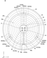
- FIG. 2 is a schematic plan view of the multi-zone heater 10.
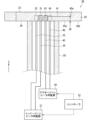
- FIG. 2 is a schematic plan view of the multi-zone heater 10.
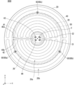
- FIG. 10 is a schematic plan view of an asymmetric multi-zone heater 1010.
- 1 is a diagram illustrating an example of a temperature distribution on a wafer mounting surface 22 when heater heating is performed in a multi-zone heater 10.
- FIG. 10 is a diagram illustrating an example of a temperature distribution on a wafer mounting surface 22 when heater heating is performed in an asymmetric multi-zone heater 1010.
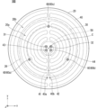
- FIG. FIG. 2 is a schematic plan view of a multi-zone heater 10B.
- 10 is a diagram illustrating an example of a temperature distribution on a wafer mounting surface 22 when heater heating is performed in a multi-zone heater 10B.
- FIG. FIG. 2 is a schematic plan view of a multi-zone heater 10C.
- Fig. 1 is a schematic plan view of a multi-zone heater 10 according to an embodiment of the present invention.
- Fig. 2 is a schematic plan view of the multi-zone heater 10.
- the xyz coordinate system is a right-handed system in which the left-right direction as viewed in the drawing is the x-axis direction, and the z-axis direction in Fig. 2 also coincides with that in Fig. 1.
- the multi-zone heater 10 is used as a support table (susceptor) that supports a semiconductor wafer downward in a semiconductor wafer heating step, which is one step in the semiconductor manufacturing process.
- a more specific example of such a heating step is the heating of a wafer in a step of forming a semiconductor thin film on the wafer by plasma CVD.
- the multi-zone heater 10 is used by being incorporated inside a semiconductor manufacturing device (not shown), such as a known plasma CVD device.
- the multi-zone heater 10 mainly comprises a ceramic base 20, an inner zone heater 30, an outer zone heater 40, a first lead wire 41, a second lead wire 42, and a shaft 50.
- the ceramic base 20 is a disk-shaped plate member made of a sintered ceramic material.
- ceramic materials include aluminum nitride, silicon carbide, silicon nitride, and aluminum oxide.
- the ceramic base 20 has, for example, a diameter of 320 mm to 385 mm and a thickness of 10 mm to 30 mm.
- One main surface of the ceramic base 20 (the upper surface in FIG. 2) serves as the wafer mounting surface 22.
- the wafer mounting surface 22 may have multiple projections and recesses formed by embossing, or multiple grooves may be formed.
- the ceramic base 20 is also provided with a plurality of lift pin holes 60, which are through holes.
- Support pins (lift pins) that are provided in a semiconductor manufacturing device (not shown) and that can support downward and raise and lower a wafer placed on the upper surface of the ceramic base can be freely inserted into the plurality of lift pin holes 60.
- the plurality of lift pin holes 60 are provided at equal angular intervals in the circumferential direction at positions equidistant from the axial center C of the ceramic base 20 (i.e., on a circle concentric with the ceramic base 20) and arranged in line symmetry (symmetrical about the y axis in FIG. 1).
- FIG. 1 shows an example in which three lift pin holes 60 (60a to 60c) are arranged in line symmetry, but the number of lift pin holes 60 is not limited to this.
- the shaft 50 is a hollow cylindrical member made of a sintered ceramic material similar to that of the ceramic base 20.
- the ceramic base 20 is divided into an inner zone 20a and an outer zone 20b by a virtual boundary circle 26, which is conceived as a circle concentric with the ceramic base 20.
- the inner zone 20a is a circular area inside the virtual boundary circle 26.
- the outer zone 20b is an annular area outside the virtual boundary circle 26.
- the virtual boundary circle 26 is set slightly inside the position of the lift pin hole 60 in the radial direction.
- An inner zone heater 30 is embedded in the inner zone 20a, and an outer zone heater 40 is embedded in the outer zone 20b.
- the inner zone heater 30 is a coil wired throughout the inner zone 20a in a plane (xy plane) parallel to the wafer mounting surface 22 inside the ceramic base 20.
- the inner zone heater 30 is wired in a single stroke while being folded back in a curve at folding portions 35 (35a-35d) near the yz plane passing through the axial center C.
- the outer zone heater 40 is a coil wired across the entire outer zone 20b within the same plane (xy plane) as the inner zone heater 30 inside the ceramic base 20. In the case shown in FIG. 1, the outer zone heater 40 is wired in a single stroke while being folded back in a curve at the folding portion 47 (47a, 47b) near the yz plane passing through the axial center C.
- the inner zone heater 30 and the outer zone heater 40 are arranged in the shape of arcs that are equally spaced in the radial direction of the ceramic base 20, that is, in the shape of concentric arcs, in most parts except for the folded portion 35 and the folded portion 47.
- the inner zone heater 30 and the outer zone heater 40 are locally provided with curved portions 36 and 48, respectively, to suppress the occurrence of temperature unevenness caused by the presence of the lift pin holes 60.
- the inner zone heater 30 has curved portions 36a, 36b, and 36c that are curved radially outward near the lift pin holes 60a, 60b, and 60c, respectively.
- the outer zone heater 40 also has curved portions 48a and 48b that curve radially outward near the lift pin holes 60a and 60b, respectively.
- the materials used for the coils that make up the inner zone heater 30 and the outer zone heater 40 include molybdenum, tungsten, or molybdenum/tungsten compounds.
- the number of turns per unit length of the coils constituting the inner zone heater 30 and the outer zone heater 40 may be appropriately changed depending on the location within the inner zone 20a and the outer zone 20b. For example, when plasma heating a wafer, temperature unevenness may occur on the wafer due to partial differences in the plasma heat input to the wafer, and the number of turns per unit length may be changed depending on the location to eliminate such temperature unevenness. The more turns a coil has per unit length, the more heat it generates and the more likely it is to reach a high temperature. Instead of changing the number of turns of the coil, the winding diameter or the line distance (the distance between adjacent coils) may be changed.
- the two ends of the inner zone heater 30 are connected to a first power supply terminal 31 and a second power supply terminal 32 disposed in the center (near the axial center C) of the ceramic base 20. As shown in FIG. 2, the first power supply terminal 31 and the second power supply terminal 32 are disposed in the same plane.
- the two ends 40a, 40b of the outer zone heater 40 are connected to one end of the first lead wire 41 and one end of the second lead wire 42, respectively, and the other end of the first lead wire 41 and the other end of the second lead wire 42 are connected to a third power supply terminal 43 and a fourth power supply terminal 44 disposed near the axial center C of the ceramic base 20. As shown in FIG. 2, the third power supply terminal 43 and the fourth power supply terminal 44 are provided in the same plane.
- the first leader 41 and the second leader 42 are arranged in a manner that crosses the inner zone 20a.
- FIG. 2 shows a schematic diagram of the first leader 41 crossing the inner zone 20a in a plane perpendicular to the z-axis. More specifically, as shown in FIG. 1, the first leader 41 and the second leader 42 are arranged between the two paired folded portions 35a and 35b of the inner zone heater 30.
- the first lead wire 41 and the second lead wire 42 are made of wire.
- the wire material include molybdenum, tungsten, and molybdenum/tungsten compounds.
- the wire diameter is not particularly limited, but is preferably 0.3 mm or more and 1.0 mm or less, for example.
- the first lead 41 and the second lead 42 are linear and symmetrical to each other along the y-axis passing through the axial center C. In other words, they are provided along the axis of symmetry of the line-symmetric arrangement of the lift pin holes 60. It is not essential that they are linear, and as long as they are line-symmetric, they may have a meandering shape (i.e., a meandering shape) or a curved shape when viewed in plan.
- the first lead 41 and the second lead 42 being line-symmetrical includes cases where they are positioned approximately symmetrically, and a degree of deviation that inevitably occurs during manufacturing is allowed. For example, a deviation of about 4 mm or less from the original line-symmetrical position is allowed. A positional deviation of this degree does not deteriorate the thermal uniformity described below.
- the first power supply terminal 31 and the second power supply terminal 32 are also connected to power supply members 33 and 34, which are power supply lines from the inner zone heater power supply 37.
- the third power supply terminal 43 and the fourth power supply terminal 44 are also connected to power supply members 45 and 46, which are power supply lines from the outer zone heater power supply 49.
- Various connection methods can be used for these connections, such as screws, crimping, fitting, brazing, welding, and eutectic soldering.
- the arrangement of the first power supply terminal 31 and the second power supply terminal 32, and the arrangement of the third power supply terminal 43 and the fourth power supply terminal 44 are also symmetrical with respect to the y-axis.
- Power supply members 33, 34, 45, and 46 are disposed inside shaft 50.
- Power supply members 33, 34, 45, and 46 are preferably made of metal, and more preferably made of nickel. Alternatively, they may be made of a nickel alloy such as Inconel (a registered trademark of Special Metal Corporation). Or they may be made of a tungsten/nickel composite. Examples of the shape of power supply members 33, 34, 45, and 46 include a rod shape, a wire shape, and the like.
- the multi-zone heater 10 has a configuration in which the inner zone 20a and the outer zone 20b outside it can be heated independently by separate heaters.
- the arrangement of the components is determined from the viewpoint of ensuring uniform heating on the wafer mounting surface 22.
- the inner zone heater 30 and the outer zone heater 40 have folded portions 35 and 47, but are arranged in a concentric arc shape for the majority of their portions.
- the shapes of folded portions 35 and 47 are determined so as to suppress temperature variations caused by the folding.
- the curved portion 36 of the inner zone heater 30 and the curved portion 48 of the outer zone heater 40 which are provided near the lift pin hole 60, are provided for the purpose of suppressing temperature variations caused by the presence of the lift pin hole 60.
- curvature radius singularities the radii of curvature of the folded-back portions 35 and 47, and the curved portions 36 and 48 are significantly different from the concentric arc-shaped portions of the inner zone heater 30 and the outer zone heater 40, and therefore these points are also referred to as curvature radius singularities.
- the inner zone heater 30 and the outer zone heater 40 are arranged so that temperature variation at the curvature radius singular point is suppressed.
- the inner zone heater 30, the outer zone heater 40, and the lift pin holes 60 are arranged in line symmetry with a common axis of symmetry. In the case shown in FIG. 1, these components are arranged symmetrically with respect to the y-axis, thereby realizing such a line symmetry arrangement.
- the first lead-out wire 41 and the second lead-out wire 42 are arranged along the axis of symmetry of the line-symmetrical arrangement.
- the arrangement of the folded-back portion 35 of the inner zone heater 30 and the arrangement of the folded-back portion 47 of the outer zone heater 40 are also line-symmetrical.
- the first lead wire 41 and the second lead wire 42 are located between a pair of turn-back portions 35 (35a, 35b), both of which are curvature radius singular points, and between a pair of turn-back portions 47 (47a, 47b), superior thermal uniformity is achieved compared to a multi-zone heater having a configuration in which the first lead wire 41 and the second lead wire 42 are provided at a position other than the axis of symmetry of the linearly symmetrical arrangement of the lift pin holes 60.
- FIG. 3 is a schematic plan view of a multi-zone heater 1010 (hereinafter, asymmetric multi-zone heater) in which the first lead wire 41 and the second lead wire 42 are provided at positions different from the axis of symmetry of the linearly symmetric arrangement of the lift pin holes 60.
- asymmetric multi-zone heater in which the first lead wire 41 and the second lead wire 42 are provided at positions different from the axis of symmetry of the linearly symmetric arrangement of the lift pin holes 60.
- the asymmetric multi-zone heater 1010 is the same as the multi-zone heater 10 shown in FIG. 1 in that the inner zone heater 30 is embedded in the inner zone 20a and the outer zone heater 40 is embedded in the outer zone 20b, and in the arrangement of the lift pin holes 60.
- most of the first lead wire 41 and the second lead wire 42 are linearly symmetrical to each other along the x-axis passing through the axial center C. Accordingly, the folded portions of the inner zone heater 30 and the outer zone heater 40 are also provided along the x-axis.
- the first lead wire 41 and the second lead wire 42 are provided at positions different from the axis of symmetry of the linearly symmetric arrangement of the lift pin holes 60.
- the arrangement of the first power supply terminal 31 and the second power supply terminal 32, and the arrangement of the third power supply terminal 43 and the fourth power supply terminal 44 are symmetrical with respect to the x-axis.
- FIGS. 4 and 5 are diagrams illustrating the temperature distribution on the wafer mounting surface 22 measured with a radiation thermometer when the set temperature was set to 550° C. and heater heating was performed in the multi-zone heater 10 and the asymmetric multi-zone heater 1010, respectively.
- the temperature distribution on the wafer placement surface 22 was generally uniform, with the maximum temperature being 552.1°C and the minimum temperature being 548.9°C. In other words, the temperature variation (the difference between the maximum and minimum temperatures) was within 3.2°C.
- the maximum temperature was 557.5°C and the minimum temperature was 547.7°C, confirming the presence of a hot spot A, which is a localized high-temperature area.
- the temperature variation reached 9.8°C. Comparing FIG. 3 with FIG. 5, it can be seen that the hot spot A is formed at the position where the first lead wire 41 and the second lead wire 42 are provided.
- the first and second lead wires 41 and 42 are short. This means that it is preferable that the diameter of the imaginary boundary circle 26 is small. However, the shorter the first and second lead wires 41 and 42 are, the smaller the inner zone 20a becomes and the larger the outer zone 20b becomes, resulting in a poor balance between the two. From the viewpoint of achieving a good balance between the heating of the inner zone 20a by the inner zone heater 30 and the heating of the outer zone 20b by the outer zone heater 40, it is preferable that the diameter of the imaginary boundary circle 26 is approximately 51% to 82% of the diameter of the ceramic base 20.
- the outer zone heater 40 will heat parts other than the edge of the wafer, which is undesirable as it becomes more difficult to adjust the temperature of the edge part.
- the diameter of the imaginary boundary circle 26 exceeds 86% of the diameter of the ceramic base 20, the temperature control ability in the outer zone 20b is significantly reduced.
- the diameter of the ceramic base 20 is 330 mm
- the diameter of the imaginary boundary circle 26 is preferably 200 mm to 260 mm.
- the diameter of the imaginary boundary circle 26 is defined as the average value (median value) of the PCD of the inner zone heater 30 located farthest from the axial center C and the PCD of the outer zone heater 40 located closest to the axial center C.
- FIG. 6 is a schematic plan view of a multi-zone heater 10B according to another embodiment of the multi-zone heater 10 shown in FIG.
- the multi-zone heater 10B has three lift pin holes 60 (60a-60c) in the inner zone 20a, and has the same configuration as the multi-zone heater 10, except that the inner zone heater 30 and the outer zone heater 40 are locally curved differently. In other words, the arrangement of the first lead wire 41 and the second lead wire 42 is the same as that of the multi-zone heater 10.
- the lift pin holes 60 should be concentric with the ceramic base 20 and located on a circle whose diameter is 46% to 88% of the diameter of the ceramic base 20. If the lift pin holes 60 are located on a circle that does not fall within this diameter range, the support of the wafer by the lift pins becomes unstable, and there is a risk of the wafer falling, which is undesirable. For example, if the diameter of the ceramic base 20 is 330 mm, then it is preferable that the lift pin holes 60 be located on a circle whose diameter is 180 mm to 280 mm.
- FIG. 7 is a diagram illustrating the temperature distribution on the wafer placement surface 22 measured with a radiation thermometer when the set temperature is set to 500° C. and heater heating is performed in the multi-zone heater 10B.
- the temperature distribution on the wafer placement surface 22 was also generally uniform, with the maximum temperature being 499.2°C and the minimum temperature being 495.9°C. In other words, the temperature variation was limited to 3.3°C.
- FIG. 8 is a schematic plan view of a multi-zone heater 10C according to yet another embodiment of the multi-zone heater 10 shown in FIG. 1.
- the arrangement of the first power supply terminal 31 and the second power supply terminal 32, and the arrangement of the third power supply terminal 43 and the fourth power supply terminal 44 are not symmetrical with respect to the y-axis, and therefore the arrangement of the first lead wire 41 and the second lead wire 42 is not symmetrical with respect to the y-axis only in the range located inside the shaft 50 in a plan view, and has the same configuration as the multi-zone heater 10.
- the thermal uniformity on the wafer placement surface when heated by the heater is improved. That is, as in the multi-zone heater 10C, the arrangement of the first power supply terminal 31 and the second power supply terminal 32 is asymmetric, and the arrangement of the third power supply terminal 43 and the fourth power supply terminal 44 is asymmetric, and therefore the asymmetric arrangement of the first lead wire 41 and the second lead wire 42 in the range located inside the shaft 50 in a plan view does not affect the thermal uniformity on the wafer placement surface 22.
- a multi-zone heater having a ceramic base with one main surface serving as a semiconductor wafer mounting surface and having a plurality of lift pin holes through which lift pins for raising and lowering the semiconductor wafer are inserted, and capable of independently heating an inner zone in the center of the ceramic base and an outer zone therearound by separate heaters
- the lift pin holes, inner zone heater, and outer zone heater are arranged in line symmetry with a common axis of symmetry, and the lead wires for supplying power to the outer zone heater are arranged symmetrically with respect to each other along the axis of symmetry.
- a multi-zone heater configured in this manner, it is possible to improve the thermal uniformity of the wafer mounting surface when heating is performed by the heater, compared to a multi-zone heater in which the lead wires are not aligned along the axis of symmetry.
- the lift pin holes 60 are provided at equal angular intervals on a circle concentric with the ceramic base 20, but an embodiment in which the lift pin holes are not at equal angular intervals is also acceptable.
- three lift pin holes may be arranged in an isosceles triangle shape other than an equilateral triangle on a circle concentric with the ceramic base 20.
- the first power supply terminal 31 and the second power supply terminal 32 are provided in the same plane
- the third power supply terminal 43 and the fourth power supply terminal 44 are provided in the same plane
- the inner zone heater 30 and the outer zone heater 40 are both arranged two-dimensionally in the xy plane.
- the first power supply terminal 31 and the second power supply terminal 32 may be provided above and below along the z-axis direction, and the inner zone heater 30 may have a three-dimensional arrangement in which the wiring is not only in the xy plane but also in the z-axis direction.
- the third power supply terminal 43 and the fourth power supply terminal 44 may be provided above and below along the z-axis direction, and the outer zone heater 40 may have a three-dimensional arrangement in which the wiring is not only in the xy plane but also in the z-axis direction.
Landscapes
- Chemical & Material Sciences (AREA)
- Engineering & Computer Science (AREA)
- Ceramic Engineering (AREA)
- Inorganic Chemistry (AREA)
- Resistance Heating (AREA)
- Container, Conveyance, Adherence, Positioning, Of Wafer (AREA)
- Surface Heating Bodies (AREA)
Abstract
Description
図1は本発明の実施の形態に係るマルチゾーンヒータ10の模式平面図である。図2はマルチゾーンヒータ10の模式平面図である。なお、図1においては、図面視左右方向をx軸方向とする右手系のxyz座標を付しており、図2のz軸方向も図1と一致させている。
図1に示したような構成を有する、本実施の形態に係るマルチゾーンヒータ10における、各構成要素の配置は、ウエハ載置面22における均熱性を確保する観点から定められてなる。
図6は、図1に示したマルチゾーンヒータ10の別態様に係るマルチゾーンヒータ10Bの模式平面図である。
上述の実施の形態においては、リフトピン穴60がセラミック基体20と同心の円上において等角度間隔にて設けられてなるが、等角度間隔ではない態様も許容される。例えば、3つのリフトピン穴が、セラミック基体20と同心の円上において正三角形ではない二等辺三角形状に配置される態様であってもよい。
Claims (4)
- 一方主面がウエハ載置面とされてなる円盤状のセラミック基体を備え、前記一方主面に載置されたウエハを加熱可能なマルチゾーンヒータであって、
前記セラミック基体に設けられてなり、前記ウエハを昇降させるためのリフトピンを挿通可能な複数のリフトピン穴と、
前記セラミック基体のインナーゾーンに埋設されてなるインナーゾーンヒータと、
前記セラミック基体の前記インナーゾーンよりも外側のアウターゾーンに埋設されてなるアウターゾーンヒータと、
前記セラミック基体の中央部に設けられてなり、前記インナーゾーンヒータの両端が接続されてなる第1の給電端子および第2の給電端子と、
前記アウターゾーンヒータの両端が接続されてなる第1引出線および第2引出線と、
前記セラミック基体の中央部に設けられてなり、前記第1引出線が接続されてなる第3の給電端子および前記第2引出線が接続されてなる第4の給電端子と、
を備え、
前記複数のリフトピン穴と前記インナーゾーンヒータと前記アウターゾーンヒータの配置が、対称軸を共通とする線対称配置とされてなり、
前記第1引出線および前記第2引出線が、前記対称軸に沿って互いに対称に設けられてなる、
ことを特徴とするマルチゾーンヒータ。 - 請求項1に記載のマルチゾーンヒータであって、
前記複数のリフトピン穴が、前記セラミック基体と同心の円上に設けられてなる、
ことを特徴とするマルチゾーンヒータ。 - 請求項2に記載のマルチゾーンヒータであって、
前記セラミック基体と同心の円の直径が、前記セラミック基体の直径の46%~88%である、
ことを特徴とするマルチゾーンヒータ。 - 請求項1ないし請求項3のいずれかに記載のマルチゾーンヒータであって、
前記インナーゾーンと前記アウターゾーンとが、前記セラミック基体と同心の仮想的な境界円にて区分され、前記境界円の直径が、前記セラミック基体の直径の51%~82%である、
ことを特徴とするマルチゾーンヒータ。
Priority Applications (7)
| Application Number | Priority Date | Filing Date | Title |
|---|---|---|---|
| KR1020247032077A KR102820998B1 (ko) | 2023-02-10 | 2023-02-10 | 멀티 존 히터 |
| PCT/JP2023/004621 WO2024166386A1 (ja) | 2023-02-10 | 2023-02-10 | マルチゾーンヒータ |
| CN202380009710.8A CN120642044A (zh) | 2023-02-10 | 2023-02-10 | 多区段加热器 |
| KR1020237024848A KR20240125839A (ko) | 2023-02-10 | 2023-02-10 | 멀티 존 히터 |
| JP2023542587A JP7376753B1 (ja) | 2023-02-10 | 2023-02-10 | マルチゾーンヒータ |
| US18/353,221 US12283496B2 (en) | 2023-02-10 | 2023-07-17 | Multi-zone heater |
| TW113102837A TW202507884A (zh) | 2023-02-10 | 2024-01-25 | 多區域加熱器 |
Applications Claiming Priority (1)
| Application Number | Priority Date | Filing Date | Title |
|---|---|---|---|
| PCT/JP2023/004621 WO2024166386A1 (ja) | 2023-02-10 | 2023-02-10 | マルチゾーンヒータ |
Related Child Applications (1)
| Application Number | Title | Priority Date | Filing Date |
|---|---|---|---|
| US18/353,221 Continuation US12283496B2 (en) | 2023-02-10 | 2023-07-17 | Multi-zone heater |
Publications (1)
| Publication Number | Publication Date |
|---|---|
| WO2024166386A1 true WO2024166386A1 (ja) | 2024-08-15 |
Family
ID=88645970
Family Applications (1)
| Application Number | Title | Priority Date | Filing Date |
|---|---|---|---|
| PCT/JP2023/004621 Ceased WO2024166386A1 (ja) | 2023-02-10 | 2023-02-10 | マルチゾーンヒータ |
Country Status (6)
| Country | Link |
|---|---|
| US (1) | US12283496B2 (ja) |
| JP (1) | JP7376753B1 (ja) |
| KR (2) | KR20240125839A (ja) |
| CN (1) | CN120642044A (ja) |
| TW (1) | TW202507884A (ja) |
| WO (1) | WO2024166386A1 (ja) |
Families Citing this family (4)
| Publication number | Priority date | Publication date | Assignee | Title |
|---|---|---|---|---|
| USD1066620S1 (en) * | 2021-02-12 | 2025-03-11 | Applied Materials, Inc. | Patterned heater pedestal with groove extensions |
| TW202427670A (zh) * | 2022-11-15 | 2024-07-01 | 荷蘭商Asm Ip私人控股有限公司 | 半導體設備以及半導體基座 |
| KR102789129B1 (ko) * | 2023-12-28 | 2025-04-03 | 주식회사 미코세라믹스 | 세라믹 서셉터 |
| WO2025187048A1 (ja) * | 2024-03-08 | 2025-09-12 | 日本碍子株式会社 | マルチゾーンヒータ |
Citations (8)
| Publication number | Priority date | Publication date | Assignee | Title |
|---|---|---|---|---|
| JP3182120U (ja) * | 2012-12-26 | 2013-03-07 | 日本碍子株式会社 | セラミックヒーター |
| JP2016115933A (ja) * | 2014-12-10 | 2016-06-23 | Toto株式会社 | 静電チャックおよびウェーハ処理装置 |
| KR20170052338A (ko) * | 2015-11-04 | 2017-05-12 | (주)포인트엔지니어링 | 서셉터 및 이를 포함하는 진공챔버 |
| WO2020153079A1 (ja) * | 2019-01-25 | 2020-07-30 | 日本碍子株式会社 | セラミックヒータ |
| WO2020153218A1 (ja) * | 2019-01-25 | 2020-07-30 | 日本碍子株式会社 | セラミックヒータ及びその製法 |
| WO2020153086A1 (ja) * | 2019-01-25 | 2020-07-30 | 日本碍子株式会社 | セラミックヒータ |
| JP2020161284A (ja) * | 2019-03-26 | 2020-10-01 | 日本碍子株式会社 | セラミックヒータ |
| JP2022065943A (ja) * | 2020-10-16 | 2022-04-28 | 日本碍子株式会社 | ウエハ載置台 |
Family Cites Families (7)
| Publication number | Priority date | Publication date | Assignee | Title |
|---|---|---|---|---|
| US6617553B2 (en) * | 1999-05-19 | 2003-09-09 | Applied Materials, Inc. | Multi-zone resistive heater |
| JP4119211B2 (ja) * | 2002-09-13 | 2008-07-16 | 日本碍子株式会社 | 加熱装置 |
| JP2006005095A (ja) * | 2004-06-16 | 2006-01-05 | Ngk Insulators Ltd | 基板加熱装置とその製造方法 |
| JP4732351B2 (ja) | 2004-07-05 | 2011-07-27 | 東京エレクトロン株式会社 | 処理装置及びヒーターユニット |
| WO2019181500A1 (ja) | 2018-03-23 | 2019-09-26 | 日本碍子株式会社 | マルチゾーンヒータ |
| JP6754514B1 (ja) * | 2019-02-19 | 2020-09-09 | 日本碍子株式会社 | セラミックヒータ及びその製法 |
| KR102539719B1 (ko) * | 2022-08-18 | 2023-06-13 | 주식회사 미코세라믹스 | 세라믹 서셉터 |
-
2023
- 2023-02-10 WO PCT/JP2023/004621 patent/WO2024166386A1/ja not_active Ceased
- 2023-02-10 KR KR1020237024848A patent/KR20240125839A/ko not_active Ceased
- 2023-02-10 KR KR1020247032077A patent/KR102820998B1/ko active Active
- 2023-02-10 JP JP2023542587A patent/JP7376753B1/ja active Active
- 2023-02-10 CN CN202380009710.8A patent/CN120642044A/zh active Pending
- 2023-07-17 US US18/353,221 patent/US12283496B2/en active Active
-
2024
- 2024-01-25 TW TW113102837A patent/TW202507884A/zh unknown
Patent Citations (8)
| Publication number | Priority date | Publication date | Assignee | Title |
|---|---|---|---|---|
| JP3182120U (ja) * | 2012-12-26 | 2013-03-07 | 日本碍子株式会社 | セラミックヒーター |
| JP2016115933A (ja) * | 2014-12-10 | 2016-06-23 | Toto株式会社 | 静電チャックおよびウェーハ処理装置 |
| KR20170052338A (ko) * | 2015-11-04 | 2017-05-12 | (주)포인트엔지니어링 | 서셉터 및 이를 포함하는 진공챔버 |
| WO2020153079A1 (ja) * | 2019-01-25 | 2020-07-30 | 日本碍子株式会社 | セラミックヒータ |
| WO2020153218A1 (ja) * | 2019-01-25 | 2020-07-30 | 日本碍子株式会社 | セラミックヒータ及びその製法 |
| WO2020153086A1 (ja) * | 2019-01-25 | 2020-07-30 | 日本碍子株式会社 | セラミックヒータ |
| JP2020161284A (ja) * | 2019-03-26 | 2020-10-01 | 日本碍子株式会社 | セラミックヒータ |
| JP2022065943A (ja) * | 2020-10-16 | 2022-04-28 | 日本碍子株式会社 | ウエハ載置台 |
Also Published As
| Publication number | Publication date |
|---|---|
| KR20250042692A (ko) | 2025-03-27 |
| US20240274446A1 (en) | 2024-08-15 |
| KR102820998B1 (ko) | 2025-06-16 |
| JPWO2024166386A1 (ja) | 2024-08-15 |
| CN120642044A (zh) | 2025-09-12 |
| KR20240125839A (ko) | 2024-08-20 |
| US12283496B2 (en) | 2025-04-22 |
| TW202507884A (zh) | 2025-02-16 |
| JP7376753B1 (ja) | 2023-11-08 |
Similar Documents
| Publication | Publication Date | Title |
|---|---|---|
| JP7376753B1 (ja) | マルチゾーンヒータ | |
| US11956863B2 (en) | Multi-zone heater | |
| US10483136B2 (en) | Ceramic heater and electrostatic chuck | |
| US7247817B2 (en) | Ceramic heater having a resistance heater element | |
| TWI816958B (zh) | 陶瓷加熱器 | |
| CN108028199B (zh) | 改善温度偏差特性的基板加热装置 | |
| TWI813839B (zh) | 陶瓷加熱器 | |
| TWI837264B (zh) | 陶瓷加熱器 | |
| US20260027666A1 (en) | Electrostatic chuck | |
| KR102581101B1 (ko) | 세라믹 히터 및 그 제법 | |
| JP2018005998A (ja) | セラミックスヒータ | |
| KR102762457B1 (ko) | 세라믹 히터 | |
| WO2025187048A1 (ja) | マルチゾーンヒータ | |
| WO2025158627A1 (ja) | セラミックヒータ | |
| WO2025163850A1 (ja) | セラミックヒータ |
Legal Events
| Date | Code | Title | Description |
|---|---|---|---|
| WWE | Wipo information: entry into national phase |
Ref document number: 2023542587 Country of ref document: JP |
|
| WWE | Wipo information: entry into national phase |
Ref document number: 202380009710.8 Country of ref document: CN |
|
| 121 | Ep: the epo has been informed by wipo that ep was designated in this application |
Ref document number: 23921215 Country of ref document: EP Kind code of ref document: A1 |
|
| WWP | Wipo information: published in national office |
Ref document number: 1020247032077 Country of ref document: KR |
|
| NENP | Non-entry into the national phase |
Ref country code: DE |
|
| WWP | Wipo information: published in national office |
Ref document number: 202380009710.8 Country of ref document: CN |
|
| 122 | Ep: pct application non-entry in european phase |
Ref document number: 23921215 Country of ref document: EP Kind code of ref document: A1 |