WO2024166371A1 - 数値制御装置、およびコンピュータ読み取り可能な記憶媒体 - Google Patents
数値制御装置、およびコンピュータ読み取り可能な記憶媒体 Download PDFInfo
- Publication number
- WO2024166371A1 WO2024166371A1 PCT/JP2023/004589 JP2023004589W WO2024166371A1 WO 2024166371 A1 WO2024166371 A1 WO 2024166371A1 JP 2023004589 W JP2023004589 W JP 2023004589W WO 2024166371 A1 WO2024166371 A1 WO 2024166371A1
- Authority
- WO
- WIPO (PCT)
- Prior art keywords
- axis
- movement amount
- area
- unit
- movement
- Prior art date
- Legal status (The legal status is an assumption and is not a legal conclusion. Google has not performed a legal analysis and makes no representation as to the accuracy of the status listed.)
- Ceased
Links
Images




Classifications
-
- B—PERFORMING OPERATIONS; TRANSPORTING
- B23—MACHINE TOOLS; METAL-WORKING NOT OTHERWISE PROVIDED FOR
- B23G—THREAD CUTTING; WORKING OF SCREWS, BOLT HEADS, OR NUTS, IN CONJUNCTION THEREWITH
- B23G1/00—Thread cutting; Automatic machines specially designed therefor
- B23G1/02—Thread cutting; Automatic machines specially designed therefor on an external or internal cylindrical or conical surface, e.g. on recesses
-
- B—PERFORMING OPERATIONS; TRANSPORTING
- B23—MACHINE TOOLS; METAL-WORKING NOT OTHERWISE PROVIDED FOR
- B23Q—DETAILS, COMPONENTS, OR ACCESSORIES FOR MACHINE TOOLS, e.g. ARRANGEMENTS FOR COPYING OR CONTROLLING; MACHINE TOOLS IN GENERAL CHARACTERISED BY THE CONSTRUCTION OF PARTICULAR DETAILS OR COMPONENTS; COMBINATIONS OR ASSOCIATIONS OF METAL-WORKING MACHINES, NOT DIRECTED TO A PARTICULAR RESULT
- B23Q15/00—Automatic control or regulation of feed movement, cutting velocity or position of tool or work
-
- G—PHYSICS
- G05—CONTROLLING; REGULATING
- G05B—CONTROL OR REGULATING SYSTEMS IN GENERAL; FUNCTIONAL ELEMENTS OF SUCH SYSTEMS; MONITORING OR TESTING ARRANGEMENTS FOR SUCH SYSTEMS OR ELEMENTS
- G05B19/00—Program-control systems
- G05B19/02—Program-control systems electric
- G05B19/18—Numerical control [NC], i.e. automatically operating machines, in particular machine tools, e.g. in a manufacturing environment, so as to execute positioning, movement or co-ordinated operations by means of program data in numerical form
Definitions
- the present disclosure relates to a numerical control device for controlling industrial machinery and a computer-readable storage medium.
- Synchronous control is a control that operates the slave axis in conjunction with the operation of the master axis.
- synchronous control is used in gear machining, thread cutting, cutting, and other processes (for example, Patent Document 1).
- the numerical control device disclosed herein includes an area information acquisition unit that acquires first area information that defines a first area in which the operation unit moves when the first axis and the second axis move synchronously at a first relative speed, and second area information that defines a second area in which the operation unit moves when the first axis and the second axis move at a second relative speed that is faster than the first relative speed, a timing search unit that searches for a phase alignment timing to align the phase of the first axis and the second axis before the operation unit starts moving in the first area, and a timing search unit that searches for a phase alignment timing to align the phase of the first axis and the second axis before the operation unit starts moving in the first area.
- the device includes a movement amount calculation unit that calculates at least one of the movement amount of the first axis and the movement amount of the second axis per unit time when the operation unit moves in the second area based on the phase alignment timing obtained, and a control unit that performs at least one of outputting first control information for controlling the first axis based on the movement amount of the first axis calculated by the movement amount calculation unit and outputting second control information for controlling the second axis based on the movement amount of the second axis calculated by the movement amount calculation unit.
- the computer-readable storage medium of the present disclosure stores instructions to cause a computer to execute at least one of the following: acquiring first area information that defines a first area in which the operation unit moves when the first axis and the second axis are synchronously moving at a first relative speed; and acquiring second area information that defines a second area in which the operation unit moves when the first axis and the second axis are moving at a second relative speed that is faster than the first relative speed; searching for a phase alignment timing for aligning the phases of the first axis and the second axis before the operation unit starts moving in the first area; calculating at least one of the movement amount of the first axis and the movement amount of the second axis per unit time when the operation unit moves in the second area based on the searched phase alignment timing; outputting first control information for controlling the first axis based on the calculated movement amount of the first axis; and outputting second control information for controlling the second axis based on the calculated movement amount of the second axis.
- FIG. 1 is a block diagram showing an example of a hardware configuration of an industrial machine
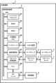
- FIG. 2 is a block diagram showing an example of a function of a numerical control device.
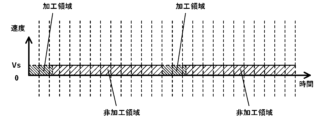
- FIG. 13 is a diagram for explaining a synchronous operation.
- FIG. 13 is a diagram showing the movement amount per unit time of the second axis.
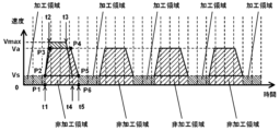
- FIG. 11 is a diagram for explaining an example of calculating a travel time.
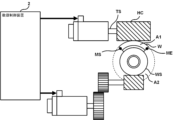
- FIG. 1 is a diagram for explaining gear machining.
- 4 is a flowchart showing an example of a flow of processing executed by a numerical control device.
- FIG. 13 is a diagram for explaining thread cutting.
- FIG. 13 is a diagram for explaining a cutting process.
- based on XX means “based on at least XX,” and includes cases where it is based on other elements in addition to XX. Furthermore, “based on XX” is not limited to cases where XX is used directly, but also includes cases where it is based on XX that has been calculated or processed. "XX” is any element (for example, any information).
- a numerical control device is a device for controlling industrial machinery.
- Industrial machinery is machinery that operates in industrial sites. Examples of industrial machinery include machine tools, cutting machines, injection molding machines, laser processing machines, 3D printers, and robots.
- FIG. 1 is a block diagram showing an example of the hardware configuration of an industrial machine in which a numerical control device is implemented.
- the industrial machine 1 includes a numerical control device 2, an input/output device 3, a servo amplifier 4, a servo motor 5, a spindle amplifier 6, a spindle motor 7, and auxiliary equipment 8.
- the numerical control device 2 includes, for example, a hardware processor 201, a bus 202, a ROM (Read Only Memory) 203, a RAM (Random Access Memory) 204, and a non-volatile memory 205.
- a hardware processor 201 for example, a hardware processor 201, a bus 202, a ROM (Read Only Memory) 203, a RAM (Random Access Memory) 204, and a non-volatile memory 205.
- the hardware processor 201 is a processor that controls the entire numerical control device 2 in accordance with a system program.
- the hardware processor 201 reads out the system program stored in the ROM 203 via the bus 202.
- the hardware processor 201 is, for example, a CPU (Central Processing Unit) or an electronic circuit.
- the bus 202 is a communication path that connects each piece of hardware in the numerical control device 2 to each other. Each piece of hardware in the numerical control device 2 exchanges data via the bus 202.
- ROM 203 is a storage device that stores system programs and the like. ROM 203 is a computer-readable storage medium.
- RAM 204 is a storage device that temporarily stores various data. RAM 204 functions as a working area for the hardware processor 201 to process various data.
- the non-volatile memory 205 is a storage device that retains data even when the power to the numerical control device 2 is turned off.
- the non-volatile memory 205 stores, for example, the operating program of the industrial machine 1.
- the non-volatile memory 205 is a computer-readable storage medium.
- the non-volatile memory 205 is, for example, a battery-backed memory or an SSD (Solid State Drive).
- the numerical control device 2 further includes an interface 206, an axis control circuit 207, a spindle control circuit 208, a PLC (Programmable Logic Controller) 209, and an I/O unit 210.
- an interface 206 an interface 206, an axis control circuit 207, a spindle control circuit 208, a PLC (Programmable Logic Controller) 209, and an I/O unit 210.
- PLC Programmable Logic Controller
- the interface 206 connects the bus 202 and the input/output device 3. For example, the interface 206 sends various data processed by the hardware processor 201 to the input/output device 3.
- the input/output device 3 receives various data via the interface 206 and displays the various data on a display.
- the input/output device 3 also receives input of various data and sends the various data via the interface 206 to, for example, the hardware processor 201.
- the input/output device 3 is, for example, a touch panel.
- the input/output device 3 is, for example, a capacitive touch panel.
- the touch panel is not limited to a capacitive touch panel, and may be a touch panel of another type.
- the input/output device 3 is installed in an operation panel (not shown) in which the numerical control device 2 is stored.
- the axis control circuit 207 is a circuit for controlling the servo motor 5.
- the axis control circuit 207 receives control commands from the hardware processor 201 and sends various commands to the servo amplifier 4 for driving the servo motor 5.
- the axis control circuit 207 sends, for example, a torque command for controlling the torque of the servo motor 5 to the servo amplifier 4.
- the servo amplifier 4 receives commands from the axis control circuit 207 and supplies current to the servo motor 5.
- the servo motors 5 are driven by receiving a current supply from the servo amplifier 4.
- the servo motors 5 are provided for each control axis of the industrial machine 1. If the industrial machine 1 is a machine tool having five axes, the servo motors 5 include, for example, an X-axis servo motor, a Y-axis servo motor, a Z-axis servo motor, an A-axis servo motor, and a C-axis servo motor.
- the axis control circuit 207 and the servo amplifier 4 are provided for each servo motor 5.
- the servo motor 5 is connected to, for example, a ball screw that drives the tool post.
- the structure of the industrial machine 1, such as the tool post moves along a specified control axis.
- the servo motor 5 has a built-in encoder (not shown) that detects the position and feed speed of the control axis. Position feedback information and speed feedback information indicating the position of the control axis and the feed speed of the control axis detected by the encoder, respectively, are fed back to the axis control circuit 207. In this way, the axis control circuit 207 performs feedback control of each control axis.
- the spindle control circuit 208 is a circuit for controlling the spindle motor 7.
- the spindle control circuit 208 receives a control command from the hardware processor 201 and sends a command to the spindle amplifier 6 to drive the spindle motor 7.
- the spindle control circuit 208 sends, for example, a spindle speed command to the spindle amplifier 6 to control the rotation speed of the spindle motor 7.
- the spindle amplifier 6 receives commands from the spindle control circuit 208 and supplies current to the spindle motor 7.
- the spindle motor 7 is driven by a current supplied from the spindle amplifier 6.
- the spindle motor 7 is connected to the main shaft and rotates the main shaft.
- the PLC 209 is a device that executes a ladder program to control the auxiliary device 8.
- the PLC 209 sends commands to the auxiliary device 8 via the I/O unit 210.
- the I/O unit 210 is an interface that connects the PLC 209 and the auxiliary device 8.
- the I/O unit 210 sends commands received from the PLC 209 to the auxiliary device 8.
- the auxiliary device 8 is installed in the industrial machine 1 and performs auxiliary operations in the industrial machine 1.
- the auxiliary device 8 operates based on commands received from the I/O unit 210.
- the auxiliary device 8 may be a device installed in the periphery of the industrial machine 1.
- the auxiliary device 8 is, for example, a tool changer, a cutting fluid injection device, or an opening/closing door drive device.
- the numerical control device 2 controls, for example, an industrial machine 1 having a first axis and a second axis.
- the numerical control device 2 causes the first axis and the second axis to operate synchronously.
- Synchronous operation means causing the slave axis to operate by following the operation of the master axis.
- the first axis is the master axis and the second axis is the slave axis.
- the numerical control device 2 synchronizes the first axis and the second axis in, for example, gear machining, thread cutting, and cutting.
- FIG. 2 is a block diagram showing an example of the functions of the numerical control device 2.
- the numerical control device 2 includes a program analysis unit 211, a first movement amount calculation unit 212, a first control unit 213, a second movement amount calculation unit 214, a second control unit 215, a phase alignment movement amount calculation unit 216, and a high-speed movement amount calculation unit 217.
- the first control unit 213 and the second control unit 215 correspond to the control units described in the claims.
- the program analysis unit 211, the first movement amount calculation unit 212, the first control unit 213, the second movement amount calculation unit 214, the second control unit 215, the phase alignment movement amount calculation unit 216, and the high-speed movement amount calculation unit 217 are realized, for example, by the hardware processor 201 performing calculation processing using the system program stored in the ROM 203 and the various data and operation programs stored in the non-volatile memory 205.
- the program analysis unit 211 analyzes the operation program of the industrial machine 1.
- the operation program is, for example, a machining program for a machine tool and a machining program for a cutting machine.
- the machining program for a machine tool is, for example, a program for gear machining and a program for thread cutting.
- the first movement amount calculation unit 212 calculates the movement amount of the first axis based on the analysis result of the operation program by the program analysis unit 211.
- the movement amount is, for example, the movement amount of the first axis per unit time.
- the movement amount calculated by the first movement amount calculation unit 212 is the movement speed of the first axis.
- the first movement amount calculation unit 212 also acquires position information indicating the position of the first axis.
- the position information is, for example, a value indicating the position or rotation angle of the first axis.
- the first movement amount calculation unit 212 acquires the position information, for example, from the servo motor 5 that drives the first axis.
- the first control unit 213 controls the first axis based on the amount of movement of the first axis calculated by the first movement amount calculation unit 212.
- the first control unit 213 controls the first axis, for example, by outputting a pulse signal corresponding to the amount of movement of the first axis.
- the second movement amount calculation unit 214 calculates the movement amount of the second axis by multiplying the movement amount of the first axis calculated by the first movement amount calculation unit 212 by a synchronization coefficient.
- the movement amount is, for example, the movement amount of the second axis per unit time.
- the movement amount calculated by the second movement amount calculation unit 214 is the movement speed of the second axis.
- the synchronization coefficient is, for example, a predetermined value, or a value calculated based on an operation program.
- the second movement amount calculation unit 214 also acquires position information indicating the position of the second axis.
- the position information is, for example, a value indicating the position or rotation angle of the second axis.
- the second movement amount calculation unit 214 acquires the position information, for example, from the servo motor 5 that drives the second axis.
- the second control unit 215 controls the second axis based on the amount of movement of the second axis calculated by the second movement amount calculation unit 214.
- the second control unit 215 controls the second axis, for example, by outputting a pulse signal corresponding to the amount of movement of the second axis.
- a constant relative speed means that the speed at which the second axis moves relative to the speed at which the first axis moves is constant. Movement includes rotation.
- first and second axes may not be in phase with each other until alignment is performed using the amount of movement calculated by the phase alignment movement amount calculation unit 216, which will be described later. Therefore, it is necessary to align the phase of the first and second axes before the gear machining, etc., described above, is performed.
- Phase refers to the positional relationship between the first axis and the second axis.
- Phase alignment refers to aligning the first axis and the second axis to a predetermined positional relationship.
- the phase alignment movement amount calculation unit 216 calculates the amount of movement for aligning the phase between the first axis and the second axis.
- the phase alignment movement amount calculation unit 216 calculates the amount of movement of at least one of the first axis and the second axis for aligning the phase between the first axis and the second axis based on position information indicating the position of the first axis and position information indicating the position of the second axis.
- the amount of movement calculated by the phase alignment movement amount calculation unit 216 corresponds to the amount of phase shift between the first axis and the second axis.
- the phase alignment movement amount calculation unit 216 obtains position information indicating the position of the first axis and position information indicating the position of the second axis from the first movement amount calculation unit 212 and the second movement amount calculation unit 214, respectively.
- the phase alignment movement amount calculation unit 216 outputs the calculated movement amount to, for example, the second control unit 215.
- the second control unit 215 performs phase alignment based on the amount of movement calculated by the phase alignment movement amount calculation unit 216. That is, the second control unit 215 increases or decreases the output of the pulse signal by an amount equivalent to the amount of movement calculated by the phase alignment movement amount calculation unit 216. This causes phase alignment between the first axis and the second axis, and the first axis and the second axis operate synchronously while being in phase with each other.
- FIG. 3A is a diagram for explaining the synchronous operation of the first axis and the second axis.
- FIG. 3A shows the rotation angles of the first axis and the second axis when they are operating synchronously.
- the first axis and the second axis each rotate at a constant rotation speed. Synchronous operation is performed in which the second axis rotates once while the first axis rotates 13 times.
- FIG. 3B is a diagram showing the amount of movement of the second axis per unit time.
- the second axis rotates at a constant amount of movement Vs per unit time.
- the second control unit 215 outputs a constant pulse signal per unit time.
- FIG. 3B also shows that the operating unit of the industrial machine 1 moves between the first area and the second area.
- the operating unit is a part of the industrial machine 1, and is a part that performs some operation on an object.
- the operating unit is, for example, a tool.
- the tool is, for example, a hob cutter, a thread cutting tool, a cutting tool, a milling tool, and a cutting tool.
- the object is, for example, a workpiece.
- the first area is a machining area.
- a machining area is an area where machining is performed by a tool.
- the second area is a non-machining area.
- a non-machining area is an area where machining is not performed by a tool.
- FIG. 4 is a diagram for explaining gear cutting.
- the gear cutting tool is, for example, a hob cutter HC.
- the hob cutter HC is fixed to, for example, a tool spindle TS.
- the tool spindle TS rotates by A-axis control.
- the A-axis corresponds to the first axis described above.
- the workpiece W is, for example, a sector gear.
- the workpiece W is gripped, for example, by a chuck fixed to the workpiece spindle WS and rotates at a constant speed.
- the workpiece spindle WS rotates under C-axis control.
- the C-axis corresponds to the second axis described above.
- the hob cutter HC and the workpiece W are positioned at the phase alignment position.
- machining of the workpiece W begins.
- the hob cutter HC moves through the first region to machine the workpiece W.
- the high-speed movement amount calculation unit 217 calculates the amount of movement for moving the operation unit at high speed along the second area A2.
- the amount of movement calculated by the high-speed movement amount calculation unit 217 is the amount of movement that is superimposed on the amount of movement of the second axis calculated by the second movement amount calculation unit 214.
- a method for moving the operation unit at high speed along the second area A2 will be described.
- the first control unit 213 When the first control unit 213 and the second control unit 215 synchronize the operation of the first axis and the second axis, the first control unit 213 outputs a constant pulse signal per unit time based on the movement amount of the first axis calculated by the first movement amount calculation unit 212.
- the second control unit 215 outputs a constant pulse signal per unit time based on the movement amount of the second axis calculated by the second movement amount calculation unit 214.
- the first axis and the second axis operate synchronously with the phase matched.
- the second control unit 215 when the second control unit 215 moves the operation unit at high speed along the second area A2, the second control unit 215 outputs a movement amount obtained by superimposing the second axis movement amount calculated by the high-speed movement amount calculation unit 217 on the second axis movement amount calculated by the second movement amount calculation unit 214.
- the second control unit 215 outputs a pulse signal corresponding to the second axis movement amount calculated by the high-speed movement amount calculation unit 217 in addition to a pulse signal corresponding to the second axis movement amount calculated by the second movement amount calculation unit 214 per unit time.
- the first control unit 213 may output a constant pulse signal per unit time based on the amount of movement of the first axis calculated by the first movement amount calculation unit 212.
- the high-speed movement amount calculation unit 217 includes an area information acquisition unit 221, a timing search unit 222, and a movement amount calculation unit 223.
- the area information acquisition unit 221 acquires first area information that defines the first area A1. As described above, the first area A1 is the machining area. Furthermore, the first area A1 is an area in which the operation unit moves with the first axis and the second axis moving synchronously at a first relative speed. The area information acquisition unit 221 acquires the first area information from the operation program analyzed by the program analysis unit 211.
- the first area information is, for example, coordinate values that define the first area A1.
- the coordinate values that define the first area A1 are the coordinate values of the machining start position MS and the coordinate values of the machining end position ME.
- the area information acquisition unit 221 further acquires second area information that defines the second area A2.
- the area information acquisition unit 221 acquires the second area information from the operation program analyzed by the program analysis unit 211.
- the second area A2 is a non-machining area.
- the second area A2 is also an area in which the operating part moves while the first axis and the second axis are moving at a second relative speed that is faster than the first relative speed.
- the second area A2 is an area in which the operating part moves at a speed faster than the speed at which it moves in the first area A1.
- the second area information may include information indicating the position of one end of the second area A2, and information indicating the movement distance when the operation unit moves through the second area A2.
- the position of one end of the second area A2 is the processing end position ME.
- the movement distance is expressed, for example, by the longitudinal length of the second area A2, or the rotation angle of the second axis.
- the second area information is, for example, information indicating the coordinate value of the machining end position ME and the clockwise rotation angle of the second axis from the machining end position ME to the machining start position MS.
- the machining end position ME and the machining start position MS are the start position and the end position of the second area A2, respectively.
- the second region information may include information indicating the positions of one end and the other end of the second region A2. That is, the second region information may be the coordinate values of the start position of the second region A2 and the coordinate values of the end position of the second region A2.
- the operating unit moves in the second area A2 at a faster speed than the moving speed in the first area A1.
- the positional relationship between the first axis and the second axis in the synchronous operation is shifted.
- the phase of the first axis and the second axis is shifted. Therefore, when the operating unit moves again in the first area A1, it is necessary to adjust the shifted phase again.
- the timing search unit 222 searches for a phase alignment timing for aligning the phases of the first axis and the second axis before the operation unit starts moving in the first area A1.
- the timing search unit 222 calculates the movement time required for the operation unit to move in the second area A2 based on, for example, information indicating the maximum speed and maximum acceleration of the second axis.
- FIG. 3C is a diagram for explaining an example in which the timing search unit 222 calculates the movement time.
- the timing search unit 222 calculates the shortest movement time for the operation unit to move in the second area A2.
- the timing search unit 222 calculates the time (t2-t1) it takes for the second axis to move at maximum acceleration from the synchronous operation speed Vs to the maximum speed Vmax at the start position of the second region A2, and the movement distance Sa at that time.
- the timing search unit 222 also calculates the time (t4-t3) it takes for the second axis to decelerate at minimum acceleration from the maximum speed Vmax to the synchronous operation speed Vs, and the movement distance Sd at that time.
- the timing search unit 222 calculates the time (t3-t2) for the second axis to move through the second area A2 at the maximum speed Vmax based on the movement distance when the operating unit moves through the second area A2, the movement distance Sa, the movement distance Sd, and the maximum speed Vmax. This allows the timing search unit 222 to calculate the shortest movement time (t4-t1) required for the operating unit to move through the second area A2.
- the timing search unit 222 further calculates, as the phase alignment timing, the timing at which the shortest movement time required for the operation unit to move through the second area A2 has elapsed, or the timing at which the phases of the first axis and the second axis can be aligned for the first time after the movement time has elapsed.
- the first axis moves based on the movement amount calculated by the first movement amount calculation unit 212. Therefore, even if the operation unit moves through the second area A2 in the shortest time, there are cases where the first axis has not yet reached the phase alignment position when the operation unit reaches the machining start position MS. Therefore, the timing at which the first axis reaches the phase alignment position after the operation unit reaches the machining start position MS is the phase alignment timing.
- the phase alignment timing is, for example, the timing when the rotation angle of the first axis is 0° and the operation unit is positioned at the start position of the first area A1.
- the timing search unit 222 calculates timing t5 as the phase alignment timing.
- the movement amount calculation unit 223 calculates the movement amount of the second axis per unit time when the operation unit moves in the second area A2, based on the phase alignment timing searched for by the timing search unit 222. In other words, the movement amount calculation unit 223 calculates the movement amount of the second axis per unit time so that the operation unit reaches the phase alignment position at the phase alignment timing.
- the movement amount calculated by the movement amount calculation unit 223 is the movement amount equivalent to the area of the trapezoid surrounded by points P2, P3, P4, and P5.
- the movement amount calculation unit 223 first calculates the movement amount equivalent to the area of the hexagon (the hatched portion that slopes upward to the right) surrounded by points P1, P2, P3, P4, P5, and P6.
- the area of this hexagon matches the area of the portion (the hatched portion that slopes upward to the right) that indicates the movement amount of the second region A2 in Figure 3B.
- the movement amount calculation unit 223 subtracts the movement amount corresponding to the rectangular portion surrounded by points P1, P2, P5, and P6 from the movement amount corresponding to the hexagonal portion.
- the area of the rectangular portion surrounded by points P1, P2, P5, and P6 corresponds to the movement amount of the second axis calculated by the second movement amount calculation unit 214.
- the movement amount of the rectangular portion is the movement amount constantly calculated by the second movement amount calculation unit 214 during synchronous operation.
- the movement amount calculation unit 223 calculates the movement amount corresponding to the area of the trapezoidal portion surrounded by points P2, P3, P4, and P5.
- the second control unit 215 outputs second control information for controlling the second axis based on the amount of movement of the second axis calculated by the movement amount calculation unit 223. That is, the second control information output by the second control unit 215 when the operation unit moves in the second area A2 is information indicating the amount of movement calculated by the second movement amount calculation unit 214 superimposed on the amount of movement calculated by the movement amount calculation unit 223.
- the numerical control device 2 can move the operation part in the second area A2 faster than it moves in the first area A1.
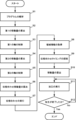
- FIG. 5 is a flowchart showing an example of the flow of processing executed by the numerical control device 2.
- the program analysis unit 211 analyzes the operation program (step S1).
- the first movement amount calculation unit 212 calculates the movement amount of the first axis based on the analysis result of the operation program by the program analysis unit 211 (step S2).
- the first control unit 213 controls the first axis based on the movement amount of the first axis calculated by the first movement amount calculation unit 212 (step S3).
- the second movement amount calculation unit 214 multiplies the movement amount of the first axis calculated by the first movement amount calculation unit 212 by a synchronization coefficient to calculate the movement amount of the second axis (step S4).
- the second control unit 215 controls the second axis based on the movement amount of the second axis calculated by the second movement amount calculation unit 214 (step S5).
- the phase alignment movement amount calculation unit 216 calculates the movement amount for aligning the phase between the first axis and the second axis (step S6).
- the second control unit 215 performs phase alignment between the first axis and the second axis based on the movement amount calculated by the phase alignment movement amount calculation unit 216 (step S7).
- the first axis and the second axis operate synchronously with the phases aligned.
- the area information acquisition unit 221 acquires the first area information and the second area information (step S8).
- the timing search unit 222 searches for a phase alignment timing for aligning the phases of the first axis and the second axis before the operation unit starts moving in the first area A1 (step S9).
- the movement amount calculation unit 223 calculates the movement amount of the second axis per unit time when the operation unit moves in the second area A2 based on the phase alignment timing searched for by the timing search unit 222 (step S10).
- the first control unit 213 and the second control unit 215 control the first axis and the second axis to process the object (step S11).
- the operation unit moves in the first area A1. That is, processing of the processing area is performed.
- the first control unit controls the first axis based on the movement amount calculated by the first movement amount calculation unit 212.
- the second control unit controls the second axis based on the movement amount calculated by the second movement amount calculation unit 214.
- the operation unit When the operation unit reaches the start position of the second area A2, the operation unit moves through the second area at high speed. At this time, the first control unit controls the first axis based on the movement amount calculated by the first movement amount calculation unit 212.
- the second control unit controls the second axis based on the movement amount calculated by the movement amount calculation unit 223 superimposed on the movement amount calculated by the second movement amount calculation unit 214.
- the second control unit again controls the second axis based on the movement amount calculated by the second movement amount calculation unit 214.
- step S12 The machining continues until the execution of the operation program is completed (if No in step S12), and when the machining is completed (if Yes in step S12), the processing in the numerical control device 2 is completed.
- the movement amount calculation unit 223 calculates the movement amount of the second axis per unit time when the operation unit moves through the second area A2, based on the phase alignment timing searched for by the timing search unit 222.
- the movement amount calculation unit 223 may also calculate the movement amount of the first axis per unit time when the operation unit moves through the second area A2, based on the phase alignment timing searched for by the timing search unit 222.
- the movement amount calculation unit 223 may calculate both the movement amount of the first axis and the movement amount of the second axis per unit time.
- the first control unit 213 may output first control information for controlling the first axis based on the movement amount of the first axis calculated by the movement amount calculation unit 223.
- the timing search unit 222 calculates the movement time required for the operation unit to move through the second area A2 based on information indicating the maximum speed and maximum acceleration of the second axis. However, the timing search unit 222 may also calculate the movement time required for the operation unit to move through the second area A2 based on information indicating the maximum speed and maximum acceleration of the first axis.
- the second control unit 215 when the operation unit is moved along the second area A2, the second control unit 215 outputs information indicating the amount of movement obtained by superimposing the amount of movement of the second axis calculated by the movement amount calculation unit 223 on the amount of movement of the second axis calculated by the second movement amount calculation unit 214.
- the first control unit 213 may output information indicating the amount of movement obtained by superimposing the amount of movement of the first axis calculated by the movement amount calculation unit 223 on the amount of movement of the first axis calculated by the first movement amount calculation unit 212.
- the first control unit 213 and the second control unit 215 may each output this information.
- the high-speed movement amount calculation unit 217 calculates a movement amount to be superimposed on the movement amount of the second axis calculated by the second movement amount calculation unit 214. Therefore, the second control unit 215 superimposes the movement amount calculated by the movement amount calculation unit 223 on the movement amount calculated by the second movement amount calculation unit 214 and outputs the result.
- the amount of movement calculated by the high-speed movement amount calculation unit 217 may be the amount of movement of the second axis when the operating unit moves in the second area A2.
- the second control unit 215 controls the second axis based only on the amount of movement calculated by the high-speed movement amount calculation unit 217.
- the second control unit 215 controls the second axis without using the amount of movement of the second axis calculated by the second movement amount calculation unit 214.
- the amount of movement of the second axis when the operating part moves in the second area A2 is the amount of movement equivalent to the area of the hexagon (the hatched area slanting upward to the right) surrounded by points P1, P2, P3, P4, P5, and P6 in Figure 3C.
- the second control unit 215 controls the second axis based on the movement amount calculated by the second movement amount calculation unit 214.
- the second control unit 215 controls the second axis based on the movement amount calculated by the high-speed movement amount calculation unit 217 and corresponding to the area of the hexagon.
- FIG. 6 is a diagram for explaining thread cutting.
- the thread cutting tool is, for example, a thread cutting tool TT.
- the thread cutting tool TT is, for example, fixed to a tool rest.
- the tool rest moves by X-axis control and Z-axis control.
- the Z-axis corresponds to the second axis described above. In other words, the Z-axis is the slave axis.
- the workpiece W is, for example, a shaft having a first thread portion T1 and a second thread portion T2.
- the workpiece W is gripped by a chuck fixed to the workpiece spindle WS and rotates at a constant speed.
- the workpiece spindle WS rotates under C-axis control.
- the C-axis corresponds to the first axis described above. In other words, the C-axis is the master axis.
- the thread cutting bit TT and the workpiece W are first positioned at the phase alignment position PP. Once the thread cutting bit TT and the workpiece W are positioned at the phase alignment position PP, machining of the workpiece W begins. That is, the thread cutting bit TT moves between the first thread portion T1 and the second thread portion T2 to machine the workpiece W. These first thread portion T1 and second thread portion T2 correspond to the first area A1.
- the thread cutting bit TT When the thread cutting bit TT passes through the first thread portion T1, the thread cutting bit TT moves through the second region A2. Furthermore, when the thread cutting bit TT passes through the second region A2, the thread cutting bit TT moves through the second thread portion T2. When the thread cutting bit TT passes through the second thread portion T2, the thread cutting bit TT is again positioned at the phase alignment position PP. By repeating this operation, the thread cutting bit TT machines a shaft having a first thread portion T1 and a second thread portion T2.
- the high-speed movement amount calculation unit 217 calculates the movement amount for moving the thread cutting bit TT at high speed along the second area A2.
- the area information acquisition unit 221 acquires first area information that defines the first area A1.
- the area information acquisition unit 221 acquires the first area information from the operation program analyzed by the program analysis unit 211.
- the coordinate values that define the first area A1 are the coordinate values of the machining start position MS and the machining end position ME of the second thread portion T2.
- the area information acquisition unit 221 further acquires second area information that defines the second area A2.
- the area information acquisition unit 221 acquires the second area information from the operation program analyzed by the program analysis unit 211.
- the second area information is the coordinate value of the machining end position ME of the first thread portion T1 and the coordinate value of the machining start position MS of the second thread portion T2.
- the operating part moves in the second area A2 at a faster speed than the moving speed in the first area A1.
- the first axis rotates at a constant speed
- the positional relationship between the first axis and the second axis in the synchronous operation is shifted.
- the phase of the first axis and the second axis is shifted. Therefore, when the operating part moves in the second screw part T2, the shifted phase needs to be realigned.
- the timing search unit 222 searches for a phase alignment timing for aligning the phases of the first axis and the second axis before the operating unit starts moving in the second screw portion T2.
- the timing search unit 222 calculates the movement time required for the operating unit to move in the second area A2 based on information indicating, for example, the maximum speed and maximum acceleration of the second axis.
- the phase alignment timing is, for example, the timing when the rotation angle of the first shaft is 0° and the operating part is positioned at the machining start position MS of the second threaded part T2.
- the second control unit 215 outputs second control information for controlling the second axis based on the movement amount of the second axis calculated by the movement amount calculation unit 223.
- the second control information output by the second control unit 215 is information indicating the movement amount calculated by the second movement amount calculation unit 214 superimposed with the movement amount calculated by the movement amount calculation unit 223. This allows the second control unit 215 to move the thread cutting tool TT at high speed when it moves through the second area A2.
- FIG. 7 is a diagram for explaining cutting processing.
- the cutting tool CT is fixed to, for example, the rotation axis RS.
- the rotation axis RS corresponds to the first axis described above. In other words, the rotation axis RS is the master axis.
- the workpiece W is, for example, a plate material.
- a number of plate materials are placed on the conveyor belt CB and move at a constant speed.
- the plate materials are placed on the conveyor belt CB at a predetermined interval.
- the conveyor belt CB moves, for example, by the rotation of the drive shaft DS.
- the drive shaft DS corresponds to the second shaft described above. In other words, the drive shaft DS is the slave shaft.
- the cutting tool CT and the workpiece W are positioned at the phase alignment position. Once the cutting tool CT and the workpiece W are positioned at the phase alignment position, cutting of the workpiece W begins. That is, the cutting tool CT rotates at a constant speed, and the workpiece W moves on the conveyor belt CB at a constant speed, thereby cutting the workpiece W to a predetermined length.
- a second area A2 where no workpiece W is placed passes under the cutting tool CT. Furthermore, when the second area A2 passes under the cutting tool CT, another workpiece W passes under the cutting tool CT.
- the area where the workpiece W is placed is the first area A1 described above.
- the high-speed movement amount calculation unit 217 calculates the amount of movement for the second area A2 to move at high speed under the cutting tool CT.
- the area information acquisition unit 221 acquires first area information that defines the first area A1.
- the area information acquisition unit 221 acquires the first area information based on detection information by the sensor S.
- the sensor S is, for example, a camera.
- the coordinate values that define the first area A1 are the coordinate values of the position of one end of the workpiece W and the coordinate values of the position of the other end of the workpiece W.
- the area information acquisition unit 221 further acquires second area information that defines the second area A2.
- the area information acquisition unit 221 acquires the second area information based on the detection information by the sensor S.
- the second area information is the coordinate values of the position of the other end of one workpiece W and the coordinate values of the position of one end of another workpiece W.
- the operating unit moves in the second area A2 at a speed faster than the moving speed in the first area A1.
- the operating unit is a cutting tool CT.
- the moving speed is the relative speed between the operating unit and the first area A1, and the relative speed between the operating unit and the second area A2.
- the positional relationship between the first axis and the second axis in the synchronous operation will shift. In other words, the phases of the first axis and the second axis will shift. Therefore, when the operating unit moves through the first area A1 again, the shifted phase must be adjusted again.
- the timing search unit 222 searches for a phase alignment timing for aligning the phases of the first axis and the second axis before the operation unit starts moving in the second area A2.
- the timing search unit 222 calculates the movement time required for the operation unit to move in the second area A2 based on, for example, information indicating the maximum speed and maximum acceleration of the second axis.
- the phase alignment timing is, for example, when the rotation angle of the first axis is 40° and the cutting start position CS of the workpiece W contacts the cutting edge of the cutting tool CT.
- the second control unit 215 outputs second control information for controlling the second axis based on the movement amount of the second axis calculated by the movement amount calculation unit 223.
- the second control information output by the second control unit 215 is information indicating the movement amount calculated by the second movement amount calculation unit 214 superimposed with the movement amount calculated by the movement amount calculation unit 223. This allows the second control unit 215 to move the cutting tool CT at high speed when it moves through the second area A2.
- the numerical control device 2 includes an area information acquisition unit 221 that acquires first area information that defines a first area A1 in which the operation unit moves when the first axis and the second axis move synchronously at a first relative speed, and second area information that defines a second area A2 in which the operation unit moves when the first axis and the second axis move at a second relative speed that is faster than the first relative speed, a timing search unit 222 that searches for a phase alignment timing for aligning the phase of the first axis and the second axis before the operation unit starts moving in the first area A1, and a timing search unit 222 that searches for a phase alignment timing for aligning the phase of the first axis and the second axis before the operation unit starts moving in the first area A1.
- control unit that performs at least one of outputting first control information for controlling the first axis based on the amount of movement of the first axis calculated by the movement amount calculation unit 223 and outputting second control information for controlling the second axis based on the amount of movement of the second axis calculated by the movement amount calculation unit 223.
- the numerical control device 2 can shorten the machining time of the workpiece W when the first axis and the second axis are operated synchronously.
- the timing search unit 222 also calculates the movement time required for the operation unit to move through the second area A2 based on information indicating the maximum speed and maximum acceleration of at least one of the first axis and the second axis, and calculates the timing at which the movement time has elapsed or the timing at which the phases first align after the movement time has elapsed as the phase alignment timing.
- the numerical control device 2 can align the phases of the first axis and the second axis at the earliest phase alignment timing. As a result, the numerical control device 2 can shorten the machining time of the workpiece W.
- control unit moves the operation unit along the second area A2
- the control unit at least performs one of the following: outputting information indicating the amount of movement obtained by superimposing the amount of movement of the first axis calculated by the movement amount calculation unit 223 on the amount of movement of the first axis; and outputting information indicating the amount of movement obtained by superimposing the amount of movement of the second axis calculated by the movement amount calculation unit 223 on the amount of movement of the second axis.
- the numerical control device 2 can move the operation unit at high speed while performing synchronous control of the first axis and the second axis. As a result, the numerical control device 2 can shorten the machining time even during synchronous control.
- the second area information also includes information indicating the position of one end of the second area A2, and information indicating the distance traveled when the operation unit moves in the second area A2.
- the second area information may also include information indicating the positions of one end and the other end of the second area A2.
- a region information acquisition unit that acquires first region information that defines a first region in which an operation unit moves in a state in which a first axis and a second axis move synchronously at a first relative speed, and second region information that defines a second region in which the operation unit moves in a state in which the first axis and the second axis move at a second relative speed that is faster than the first relative speed;
- a timing search unit that searches for a phase alignment timing for aligning the phases of the first axis and the second axis before the operation unit starts moving in the first region;
- a movement amount calculation unit that calculates at least one of a movement amount of the first axis and a movement amount of the second axis per unit time when the operation unit moves in the second area based on a moving amount of the first axis calculated by the movement amount calculation unit, and a control unit that executes at least one of outputting first control information for controlling the first axi
- Appendix [2] The numerical control device described in Appendix [1], wherein the timing search unit calculates a movement time required for the operation unit to move through the second area based on information indicating a maximum speed and a maximum acceleration of at least one of the first axis and the second axis, and calculates, as the phase alignment timing, a timing at which the movement time has elapsed or a timing at which the phase can be aligned for the first time after the movement time has elapsed.
- Appendix [3] The numerical control device according to appendix [1] or [2], wherein, when the operation unit is moved along the second area, the control unit executes at least one of: outputting information indicating an amount of movement obtained by superimposing the amount of movement of the first axis calculated by the movement amount calculation unit on the amount of movement of the first axis; and outputting information indicating an amount of movement obtained by superimposing the amount of movement of the second axis calculated by the movement amount calculation unit on the amount of movement of the second axis.
- Appendix [4] The numerical control device according to any one of appendices [1] to [3], wherein the second area information includes information indicating a position of one end of the second area and information indicating a moving distance when the operation unit moves in the second area.
- Appendix [5] The numerical control device according to any one of appendices [1] to [3], wherein the second region information includes information indicating the positions of one end and the other end of the second region.
- Appendix [6] a first area information defining a first area in which an operation unit moves in a state in which a first axis and a second axis move synchronously at a first relative speed; and a second area information defining a second area in which the operation unit moves in a state in which the first axis and the second axis move at a second relative speed faster than the first relative speed; searching for a phase alignment timing for aligning the phases of the first axis and the second axis before the operation unit starts moving in the first area; calculating at least one of an amount of movement of the first axis and an amount of movement of the second axis per unit time when the operation unit moves in the second area based on the searched phase alignment timing; and outputting first control information for controlling the first axis based on the calculated amount of movement of the first axis, and outputting second control information for controlling the second axis based on the calculated amount of movement of the second axis.
- Reference Signs List 1 Industrial machine 2 Numerical control device 201 Hardware processor 202 Bus 203 ROM 204 RAM 205 Non-volatile memory 206 Interface 207 Axis control circuit 208 Spindle control circuit 209 PLC 210 I/O unit 211 Program analysis section 212 First movement amount calculation section 213 First control section 214 Second movement amount calculation section 215 Second control section 216 Phase alignment movement amount calculation section 217 High-speed movement amount calculation section 221 Area information acquisition section 222 Timing search section 223 Movement amount calculation section 3 Input/output device 4 Servo amplifier 5 Servo motor 6 Spindle amplifier 7 Spindle motor 8 Auxiliary equipment
Landscapes
- Engineering & Computer Science (AREA)
- Mechanical Engineering (AREA)
- Human Computer Interaction (AREA)
- Manufacturing & Machinery (AREA)
- Physics & Mathematics (AREA)
- General Physics & Mathematics (AREA)
- Automation & Control Theory (AREA)
- Numerical Control (AREA)
Priority Applications (2)
| Application Number | Priority Date | Filing Date | Title |
|---|---|---|---|
| JP2024576057A JPWO2024166371A1 (https=) | 2023-02-10 | 2023-02-10 | |
| PCT/JP2023/004589 WO2024166371A1 (ja) | 2023-02-10 | 2023-02-10 | 数値制御装置、およびコンピュータ読み取り可能な記憶媒体 |
Applications Claiming Priority (1)
| Application Number | Priority Date | Filing Date | Title |
|---|---|---|---|
| PCT/JP2023/004589 WO2024166371A1 (ja) | 2023-02-10 | 2023-02-10 | 数値制御装置、およびコンピュータ読み取り可能な記憶媒体 |
Publications (1)
| Publication Number | Publication Date |
|---|---|
| WO2024166371A1 true WO2024166371A1 (ja) | 2024-08-15 |
Family
ID=92262692
Family Applications (1)
| Application Number | Title | Priority Date | Filing Date |
|---|---|---|---|
| PCT/JP2023/004589 Ceased WO2024166371A1 (ja) | 2023-02-10 | 2023-02-10 | 数値制御装置、およびコンピュータ読み取り可能な記憶媒体 |
Country Status (2)
| Country | Link |
|---|---|
| JP (1) | JPWO2024166371A1 (https=) |
| WO (1) | WO2024166371A1 (https=) |
Citations (6)
| Publication number | Priority date | Publication date | Assignee | Title |
|---|---|---|---|---|
| JPH08202420A (ja) * | 1995-01-30 | 1996-08-09 | Fanuc Ltd | 数値制御装置の同期制御方式 |
| JP2003181722A (ja) * | 2001-12-18 | 2003-07-02 | Toyoda Mach Works Ltd | タッピング加工装置及びタッピング加工方法 |
| JP2012056066A (ja) * | 2010-09-13 | 2012-03-22 | Mitsubishi Electric Corp | ねじ切り制御方法及びその装置 |
| JP2019114192A (ja) * | 2017-12-26 | 2019-07-11 | ファナック株式会社 | 数値制御装置 |
| JP2019185287A (ja) * | 2018-04-06 | 2019-10-24 | ファナック株式会社 | 工作機械の制御装置 |
| WO2021193728A1 (ja) * | 2020-03-26 | 2021-09-30 | ファナック株式会社 | 工作機械の制御装置、制御システム、及び制御方法 |
-
2023
- 2023-02-10 JP JP2024576057A patent/JPWO2024166371A1/ja active Pending
- 2023-02-10 WO PCT/JP2023/004589 patent/WO2024166371A1/ja not_active Ceased
Patent Citations (6)
| Publication number | Priority date | Publication date | Assignee | Title |
|---|---|---|---|---|
| JPH08202420A (ja) * | 1995-01-30 | 1996-08-09 | Fanuc Ltd | 数値制御装置の同期制御方式 |
| JP2003181722A (ja) * | 2001-12-18 | 2003-07-02 | Toyoda Mach Works Ltd | タッピング加工装置及びタッピング加工方法 |
| JP2012056066A (ja) * | 2010-09-13 | 2012-03-22 | Mitsubishi Electric Corp | ねじ切り制御方法及びその装置 |
| JP2019114192A (ja) * | 2017-12-26 | 2019-07-11 | ファナック株式会社 | 数値制御装置 |
| JP2019185287A (ja) * | 2018-04-06 | 2019-10-24 | ファナック株式会社 | 工作機械の制御装置 |
| WO2021193728A1 (ja) * | 2020-03-26 | 2021-09-30 | ファナック株式会社 | 工作機械の制御装置、制御システム、及び制御方法 |
Also Published As
| Publication number | Publication date |
|---|---|
| JPWO2024166371A1 (https=) | 2024-08-15 |
Similar Documents
| Publication | Publication Date | Title |
|---|---|---|
| CN102027426B (zh) | 数控方法及其装置 | |
| KR102547810B1 (ko) | 선반 | |
| JPH046001B2 (https=) | ||
| CN103348295B (zh) | 数控装置 | |
| JP4450302B2 (ja) | 工作機械の数値制御装置 | |
| CN100496837C (zh) | 螺纹切削控制方法及其装置 | |
| US10852708B2 (en) | Numerical control device | |
| US20090271017A1 (en) | Machine tool and its program conversion method | |
| JPH07302103A (ja) | モーションコントローラ | |
| WO2024166371A1 (ja) | 数値制御装置、およびコンピュータ読み取り可能な記憶媒体 | |
| US10564630B2 (en) | Numerical controller | |
| JP2004114176A (ja) | 数値制御装置 | |
| CN112241148B (zh) | 机床的控制装置以及控制系统 | |
| EP0647892B1 (en) | Numeric controller | |
| JP6444969B2 (ja) | 数値制御装置 | |
| US12517489B2 (en) | Control device and control method for machine tool, and slave shaft control device | |
| JP2000305612A (ja) | 複数の主軸を制御可能な数値制御装置 | |
| JP7769013B2 (ja) | 数値制御装置、およびコンピュータ読み取り可能な記憶媒体 | |
| JPS6299020A (ja) | ねじ切り制御方式 | |
| JP2712881B2 (ja) | 数値制御装置 | |
| JP2002326140A (ja) | 多軸同期制御装置および多軸同期制御方法 | |
| JP2654228B2 (ja) | 数値制御装置 | |
| WO2025069313A1 (ja) | 数値制御システム | |
| JPH10166222A (ja) | 旋盤におけるネジの再加工方法 | |
| JPS62224520A (ja) | タツピング加工制御方式 |
Legal Events
| Date | Code | Title | Description |
|---|---|---|---|
| 121 | Ep: the epo has been informed by wipo that ep was designated in this application |
Ref document number: 23921200 Country of ref document: EP Kind code of ref document: A1 |
|
| WWE | Wipo information: entry into national phase |
Ref document number: 2024576057 Country of ref document: JP |
|
| NENP | Non-entry into the national phase |
Ref country code: DE |
|
| 122 | Ep: pct application non-entry in european phase |
Ref document number: 23921200 Country of ref document: EP Kind code of ref document: A1 |