WO2024166342A1 - 空気調和装置の室内機および空気調和システム - Google Patents
空気調和装置の室内機および空気調和システム Download PDFInfo
- Publication number
- WO2024166342A1 WO2024166342A1 PCT/JP2023/004503 JP2023004503W WO2024166342A1 WO 2024166342 A1 WO2024166342 A1 WO 2024166342A1 JP 2023004503 W JP2023004503 W JP 2023004503W WO 2024166342 A1 WO2024166342 A1 WO 2024166342A1
- Authority
- WO
- WIPO (PCT)
- Prior art keywords
- electric dust
- air
- indoor unit
- controller
- dust collectors
- Prior art date
- Legal status (The legal status is an assumption and is not a legal conclusion. Google has not performed a legal analysis and makes no representation as to the accuracy of the status listed.)
- Ceased
Links
Images










Classifications
-
- F—MECHANICAL ENGINEERING; LIGHTING; HEATING; WEAPONS; BLASTING
- F24—HEATING; RANGES; VENTILATING
- F24F—AIR-CONDITIONING; AIR-HUMIDIFICATION; VENTILATION; USE OF AIR CURRENTS FOR SCREENING
- F24F1/00—Room units for air-conditioning, e.g. separate or self-contained units or units receiving primary air from a central station
- F24F1/0007—Indoor units, e.g. fan coil units
- F24F1/0071—Indoor units, e.g. fan coil units with means for purifying supplied air
- F24F1/0076—Indoor units, e.g. fan coil units with means for purifying supplied air by electric means, e.g. ionisers or electrostatic separators
-
- F—MECHANICAL ENGINEERING; LIGHTING; HEATING; WEAPONS; BLASTING
- F24—HEATING; RANGES; VENTILATING
- F24F—AIR-CONDITIONING; AIR-HUMIDIFICATION; VENTILATION; USE OF AIR CURRENTS FOR SCREENING
- F24F2110/00—Control inputs relating to air properties
- F24F2110/50—Air quality properties
- F24F2110/52—Air quality properties of the outside air
-
- F—MECHANICAL ENGINEERING; LIGHTING; HEATING; WEAPONS; BLASTING
- F24—HEATING; RANGES; VENTILATING
- F24F—AIR-CONDITIONING; AIR-HUMIDIFICATION; VENTILATION; USE OF AIR CURRENTS FOR SCREENING
- F24F2110/00—Control inputs relating to air properties
- F24F2110/50—Air quality properties
- F24F2110/64—Airborne particle content
Definitions
- This disclosure relates to an indoor unit of an air conditioner that conditions the air in a space to be air-conditioned, and an air conditioning system.
- the air purification unit has a charging section that charges objects to be captured floating in the air, and a capture section that captures and removes the objects to be captured that have been charged by the charging section.
- the charging section is provided with multiple charging modules.
- the air conditioner in Patent Document 1 controls multiple charging modules by changing the voltage applied to the charging modules depending on the difference in wind speed. Specifically, it aims to reduce power consumption by lowering the voltage applied to charging modules placed in areas with slow wind speeds.
- Patent Document 1 lowers the applied voltage to the charging modules located in areas with slow wind speeds, but because the charging modules located in areas with slow wind speeds are also discharged, the effect of reducing power consumption is not sufficient.
- This disclosure has been made to solve the problems described above, and provides an indoor unit of an air conditioner and an air conditioning system that can reduce power consumption while collecting dust in the space to be air-conditioned.
- the indoor unit of the air conditioner comprises a load side heat exchanger, a blower that draws in air from a space to be air-conditioned and sends the drawn-in air to the load side heat exchanger to generate an airflow, a plurality of electric dust collectors that are provided upstream of the load side heat exchanger in the direction of the airflow and collect dust while in operation, and a controller that switches the number of electric dust collectors to be operated among the plurality of electric dust collectors.
- the air conditioning system has an air conditioning device including a load side heat exchanger, a blower that draws in air from a space to be air-conditioned and sends the drawn-in air to the load side heat exchanger to generate an airflow, and an indoor unit that is provided upstream of the load side heat exchanger in the direction of the airflow and has a plurality of electric dust collectors that collect dust while in operation, and a selection means for switching the number of electric dust collectors to be operated among the plurality of electric dust collectors.
- the number of operating electric dust collectors among multiple electric dust collectors can be switched, so that the number of operating electric dust collectors can be set to the minimum number that corresponds to the installation environment of the indoor unit, thereby reducing power consumption.
- FIG. 1 is a refrigerant circuit diagram showing a configuration example of an air conditioning apparatus according to a first embodiment.
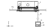
- 1 is a side view showing an example of installation of an indoor unit of an air conditioning apparatus according to Embodiment 1.
- FIG. 3 is a development view showing one configuration example of the indoor unit shown in FIG. 2 .
- FIG. 3 is a plan view of the indoor unit shown in FIG. 2 .
- FIG. 4 is an external perspective view of the intermediate unit shown in FIG. 3 .
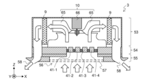
- FIG. 5 is a schematic cross-sectional view of the indoor unit shown in FIG. 4 taken along line AA.
- FIG. 6 is an external perspective view of the electric dust collector shown in FIG. 5 .
- 8 is a block diagram showing a configuration example of the electric dust collector shown in FIG. 7 .
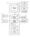
- FIG. 2 is a functional block diagram showing a configuration example of a controller shown in FIG. 1 .
- FIG. 11 is a diagram illustrating an example of information displayed on the remote controller.
- FIG. 10 is a hardware configuration diagram showing an example of the configuration of a controller shown in FIG. 9 .
- 10 is a hardware configuration diagram showing another example of the configuration of the controller shown in FIG. 9 .
- FIG. 4 is a flow diagram showing an operation procedure of an indoor unit of the air conditioning apparatus according to the first embodiment.
- FIG. 11 is a diagram showing another example of information displayed on the remote controller.
- FIG. 11 is a block diagram showing a configuration example of an air conditioning system according to a second embodiment.
- FIG. 16 is a functional block diagram showing a configuration example of a controller and a server shown in FIG. 15 .
- FIG. 1 is a refrigerant circuit diagram showing one configuration example of the air conditioner according to the embodiment 1.
- the air conditioner 1 has an outdoor unit 2, an indoor unit 3, and a remote controller 16.
- the outdoor unit 2 has a compressor 4, a four-way valve 5, an outdoor blower 6, a heat source side heat exchanger 7, an expansion valve 8, and an outdoor unit controller 21.
- the indoor unit 3 has a load side heat exchanger 9, an indoor blower 10, a dust collection module 11, and an indoor unit controller 22.
- the compressor 4, the heat source side heat exchanger 7, the expansion valve 8, and the load side heat exchanger 9 are connected by a refrigerant pipe 13 to form a refrigerant circuit 15.
- the outdoor unit controller 21 and the indoor unit controller 22 are connected via a signal line 51 to constitute the controller 20.
- the indoor unit controller 22 is connected to the remote controller 16 via a signal line 52.
- the indoor unit 3 is provided with a room temperature sensor 12 that detects the room temperature Tr, which is the temperature of the air in the space to be air-conditioned.
- the outdoor unit controller 21 is connected to each of the compressor 4, four-way valve 5, outdoor blower 6, and expansion valve 8 via signal lines not shown in the figure.
- the indoor unit controller 22 is connected to each of the indoor blower 10, dust collection module 11, and room temperature sensor 12 via signal lines not shown in the figure.
- the room temperature sensor 12 transmits information about the detected room temperature Tr to the indoor unit controller 22.
- the four-way valve 5 switches the flow direction of the refrigerant circulating through the refrigerant circuit 15.
- the flow path inside the four-way valve 5 shown in Figure 1 is as shown by the solid line.
- the flow path inside the four-way valve 5 shown in Figure 1 is as shown by the dashed line.
- the compressor 4 draws in low-temperature and low-pressure refrigerant, compresses it, and discharges it.
- the compressor 4 is an inverter compressor whose capacity can be adjusted by changing the operating frequency, for example.
- the outdoor blower 6 draws in outside air and sends it out to the heat source side heat exchanger 7.
- the outdoor blower 6 is, for example, a propeller fan.
- the indoor blower 10 draws in air from the space to be air-conditioned and sends it out to the load side heat exchanger 9.
- the indoor blower 10 is, for example, a centrifugal fan.
- the heat source side heat exchanger 7 is a heat exchanger that exchanges heat between the outside air and the refrigerant.
- the heat source side heat exchanger 7 functions as a condenser.
- the heat source side heat exchanger 7 functions as an evaporator.
- the load side heat exchanger 9 is a heat exchanger that exchanges heat between the indoor air and the refrigerant.
- the load side heat exchanger 9 functions as an evaporator.
- the load side heat exchanger 9 functions as a condenser.
- the heat source side heat exchanger 7 and the load side heat exchanger 9 are, for example, fin-and-tube type heat exchangers having a heat transfer tube and multiple heat dissipation fins.
- the expansion valve 8 reduces the pressure of the liquid refrigerant flowing in from the heat source side heat exchanger 7 and the load side heat exchanger 9, causing it to expand.
- the expansion valve 8 is, for example, an electronic expansion valve.
- FIG. 2 is a side view showing an example of installation of an indoor unit of an air-conditioning apparatus according to embodiment 1.
- the indoor unit 3 is a ceiling-embedded indoor unit that can be embedded in the ceiling PLc of a room.
- the indoor unit 3 is described as being of the ceiling-embedded type, but the indoor unit 3 may also be of a wall-mounted type that is attached to a wall, or a floor-standing type that is installed on the floor.
- the remote controller 16 has a display unit 61 that displays information to the user, and an operation unit 62 that enables the user to input instructions to the air conditioning device 1.
- the display unit 61 is, for example, a liquid crystal display.
- the operation unit 62 is composed of a number of buttons.
- the operation unit 62 may be a touch panel.
- FIG. 3 is an exploded view showing one configuration example of the indoor unit shown in FIG. 2.
- FIG. 4 is a plan view of the indoor unit shown in FIG. 2.
- the indoor unit 3 has a decorative panel 55 facing the room which is the space to be air-conditioned, an intermediate unit 54 stacked on the decorative panel 55, and a housing 53 stacked on the intermediate unit 54.
- the housing 53 houses the load side heat exchanger 9, indoor blower 10, room temperature sensor 12 and indoor unit controller 22 shown in FIG. 1.
- the intermediate unit 54 houses the dust collection module 11.
- the decorative panel 55 has an intake port 56 located in the center and four air outlets 58 located around the intake port 56.
- the intake port 56 is provided with a filter 57 that collects dust sucked in from the room.
- the indoor unit 3 is a four-way cassette type indoor unit in which the air outlets 58 are formed in four directions.
- the indoor unit 3 may also be a two-way cassette type indoor unit in which the air outlets 58 are formed in two directions.
- FIG. 5 is an external perspective view of the intermediate unit shown in FIG. 3.
- the electric dust collectors 41-1 to 41-4 are arranged in the intermediate unit 54 parallel to the XY plane. Each of the electric dust collectors 41-1 to 41-4 serves to collect dust that cannot be collected by the filter 57 shown in FIG. 4. Dust is, for example, dust or pollen floating in the air.
- FIG. 6 is a schematic cross-sectional view of the indoor unit shown in FIG. 4 taken along line A-A.
- the indoor blower 10 has blades 65 and a fan motor 66 that rotates the blades 65 via a rotating shaft.
- the arrows indicate the direction of airflow, which is the flow of air generated when the indoor blower 10 sucks in air from the room and sends it out to the load-side heat exchanger 9.
- the electric dust collectors 41-1 to 41-4 are located upstream of the load-side heat exchanger 9 in the airflow direction.
- FIG. 7 is an external perspective view of the electric dust collector shown in FIG. 5.
- FIG. 8 is a block diagram showing an example of the configuration of the electric dust collector shown in FIG. 7.
- the arrows in FIG. 8 indicate the flow direction of the airflow generated by the operation of the indoor blower 10.
- the electric dust collector 41-1 has a high-voltage power supply 42 that generates a high voltage by boosting the voltage of electricity supplied from a commercial power source (not shown), and a dust collector 43 that charges dust with the high voltage and collects it.
- a high voltage is applied individually to each of the dust collectors 43 of the electric dust collectors 41-1 to 41-4 from the high-voltage power supply 42.
- the dust collector 43 has a charged electrode 44 and a dust collector electrode 45.
- the charged electrode 44 has a charged portion 44a to which a high voltage is applied, and an opposing electrode 44b arranged opposite the charged portion 44a.
- the charged electrode 44 charges dust in the airflow flowing between the charged portion 44a and the opposing electrode 44b by discharging between the charged portion 44a and the opposing electrode 44b.
- the dust collection electrode 45 is arranged downstream in the flow direction of the airflow.
- the dust collection electrode 45 is arranged parallel to a plane perpendicular to the flow direction of the airflow, and is made of a mesh-like metal material.
- the dust collection electrode 45 is grounded.
- the dust collection electrode 45 collects the charged dust.
- FIG. 9 is a functional block diagram showing an example of the configuration of the controller shown in FIG. 1.
- Each of the outdoor unit controller 21 and the indoor unit controller 22 is, for example, a microcomputer.
- the indoor unit controller 22 receives information on room temperature Tr from the room temperature sensor 12, it transmits the information on room temperature Tr to the outdoor unit controller 21 via signal line 51.
- the indoor unit controller 22 transmits information on the input instruction to the outdoor unit controller 21 via signal line 51.
- the outdoor unit controller 21 has a refrigeration cycle control means 31.
- the refrigeration cycle control means 31 controls the compressor 4, the four-way valve 5, the expansion valve 8, and the outdoor blower 6. Specifically, when the user inputs an operation mode and an instruction to start operation of the air conditioner 1 via the remote controller 16, the refrigeration cycle control means 31 switches the flow direction of the refrigerant in the four-way valve 5 in accordance with the operation mode instructed.
- the refrigeration cycle control means 31 controls the operation frequency of the compressor 4, the opening degree of the expansion valve 8, and the rotation speed of the outdoor blower 6 so that the room temperature Tr detected by the room temperature sensor 12 approaches the set temperature Ts.
- the set temperature Ts is input to the refrigeration cycle control means 31 by the user via the remote controller 16.
- the indoor unit controller 22 has an indoor fan control means 32, a dust collection section control means 33, a selection means 34, a storage means 35, and a timer 36 that measures time.
- the indoor fan control means 32 controls the rotation speed of the indoor blower 10 in accordance with the instructed air volume.
- the indoor fan control means 32 starts the indoor blower 10 and sends an operation start signal to the dust collection section control means 33.
- the storage means 35 stores the accumulated operating time for each electric dust collector.
- the storage means 35 stores information on the power consumption of one electric dust collector.
- the storage means 35 stores the power consumption of the electric dust collectors 41-1 to 41-4 for a predetermined period Dp.
- the period Dp may be, for example, the most recent hours, the most recent day, the most recent week, the most recent month, or the most recent six months.
- the power consumption value of one electric dust collector stored in the storage means 35 may be a value determined by the specifications of the electric dust collector, or may be calculated while the air conditioner 1 is in operation. For example, while the air conditioner 1 is in operation, the power consumption of one electric dust collector 41-1 is calculated by subtracting the power consumption of the air conditioner 1 when the electric dust collector 41-1 is not in operation from the power consumption of the air conditioner 1 when the electric dust collector 41-1 is in operation.
- the selection means 34 transmits information on the number of operating units to the dust collector control means 33.
- the selection means 34 may prompt the user to input the number of operating electric dust collectors via the remote controller 16.
- the selection means 34 may refer to the information stored in the storage means 35 and display selection assistance information, which is information for assisting the user in selecting the number of operating units.
- the selection assistance information includes, for example, information on the power consumption of one electric dust collector 41-k.
- FIG. 10 is a diagram showing an example of information displayed on the remote controller.
- the selection means 34 causes the display unit 61 of the remote controller 16 to display a message prompting the user to input the number of electrostatic precipitators to be operated.
- FIG. 10 shows a case in which the selection means 34 causes the display unit 61 of the remote controller 16 to display, as auxiliary selection information, information on the power consumption of one electrostatic precipitator and information on the status of the electrostatic precipitators for the past week.
- the selection means 34 may also select an electric dust collector to be operated from among the multiple electric dust collectors 41-1 to 41-4, according to a predetermined criterion for the number of electric dust collectors to be operated designated by the user. For example, a command to automatically set the electric dust collector to be operated may be input in advance from the user via the remote controller 16.
- the selection means 34 refers to the information stored in the storage means 35, and selects the number of electric dust collectors to be operated from among the electric dust collectors 41-1 to 41-4, starting with the electric dust collector with the smallest cumulative operating time. In this case, the selection means 34 transmits designation information including information on the selected electric dust collector to the dust collector control means 33.
- the dust collector control means 33 controls the start and stop of each electric dust collector. Specifically, when starting an electric dust collector 41-k, the dust collector control means 33 starts the supply of input voltage to the high-voltage power supply 42 corresponding to the electric dust collector 41-k. When stopping an electric dust collector 41-k, the dust collector control means 33 cuts off the supply of input voltage to the high-voltage power supply 42 corresponding to the electric dust collector 41-k.
- the dust collector control means 33 receives an operation start signal from the indoor fan control means 32, it starts one electric dust collector.
- the dust collector control means 33 receives information on the number of electric dust collectors in operation from the selection means 34, it starts the operation of the received number of electric dust collectors in operation.
- the dust collector control means 33 may randomly select the electric dust collector to be operated from the electric dust collectors 41-1 to 41-4, or may select according to a user's instruction.
- the dust collection unit control means 33 receives designation information from the selection means 34, it selects the electric dust collection unit to be activated according to the designation information.
- the dust collection unit control means 33 also refers to the time measured by the timer 36 from when the air conditioning device 1 starts to operate until it stops, and calculates the operation time for each electric dust collection unit.
- the dust collection unit control means 33 then adds the operation time calculated for each electric dust collection unit to the accumulated value of the operation time of the electric dust collection unit stored by the storage means 35 via the selection means 34. This causes the accumulated value of the operation time stored by the storage means 35 to be updated for each electric dust collection unit. Note that the update of the accumulated value of the operation time for each electric dust collection unit may be performed by the selection means 34.
- FIG. 11 is a hardware configuration diagram showing an example of the configuration of the controller shown in FIG. 9.
- the controller 20 shown in FIG. 9 is configured with a processing circuit 90 as shown in FIG. 11.
- Each function of the refrigeration cycle control means 31, indoor fan control means 32, dust collection unit control means 33, selection means 34, storage means 35, and timer 36 shown in FIG. 9 is realized by the processing circuit 90.
- the processing circuit 90 corresponds to, for example, a single circuit, a composite circuit, a programmed processor, a parallel programmed processor, an ASIC (Application Specific Integrated Circuit), an FPGA (Field-Programmable Gate Array), or a combination of these.
- Each of the functions of the refrigeration cycle control means 31, the indoor fan control means 32, the dust collection unit control means 33, the selection means 34, the storage means 35, and the timer 36 may be realized by a separate processing circuit 90.
- the functions of the refrigeration cycle control means 31, the indoor fan control means 32, the dust collection unit control means 33, the selection means 34, the storage means 35, and the timer 36 may be realized by a single processing circuit 90.
- FIG. 12 is a hardware configuration diagram showing another example of the configuration of the controller shown in FIG. 9.
- the controller 20 shown in FIG. 9 is composed of a processor 91 such as a CPU (Central Processing Unit) and a memory 92, as shown in FIG. 12.
- the functions of the refrigeration cycle control means 31, the indoor fan control means 32, the dust collection section control means 33, the selection means 34, the storage means 35, and the timer 36 are realized by the processor 91 and the memory 92.
- FIG. 12 shows that the processor 91 and the memory 92 are connected to each other so as to be able to communicate with each other via a bus 93.
- the functions of the refrigeration cycle control means 31, indoor fan control means 32, dust collection unit control means 33, selection means 34, storage means 35 and timer 36 are realized by software, firmware, or a combination of software and firmware.
- the software and firmware are written as programs and stored in memory 92.
- the processor 91 realizes the function of each means by reading and executing the programs stored in memory 92.
- non-volatile semiconductor memory such as ROM (Read Only Memory), flash memory, EPROM (Erasable and Programmable ROM), and EEPROM (Electrically Erasable and Programmable ROM) may be used as the memory 92.
- Volatile semiconductor memory such as RAM (Random Access Memory) may also be used as the memory 92.
- removable recording media such as magnetic disks, flexible disks, optical disks, CDs (Compact Discs), MDs (Mini Discs), and DVDs (Digital Versatile Discs) may also be used as the memory 92.
- each of the outdoor unit controller 21 and the indoor unit controller 22 may have the hardware configuration shown in Fig. 11 or 12.
- the controller 20 may be provided in either the outdoor unit 2 or the indoor unit 3, or may be provided in a location separate from the outdoor unit 2 and the indoor unit 3.
- Figure 13 is a flow diagram showing the operation procedure of the indoor unit of the air conditioning device according to the first embodiment.
- step S1 the controller 20 determines whether an instruction to start operation of the air conditioner 1 has been input. If an instruction to start operation of the air conditioner 1 has been input (step S1: Yes), the controller 20 starts operation of the air conditioner 1 (step S2). Specifically, the refrigeration cycle control means 31 starts control of the compressor 4, four-way valve 5, expansion valve 8, and outdoor blower 6. The indoor fan control means 32 starts operation of the indoor blower 10 and sends an operation start signal to the dust collection unit control means 33.
- the dust collector control means 33 When the dust collector control means 33 receives an operation start signal from the indoor fan control means 32, it starts the operation of one of the electric dust collectors 41-1 to 41-n (step S3). At that time, for example, the dust collector control means 33 refers to the information stored in the storage means 35 and selects the electric dust collector with the shortest cumulative operating time as the one to be operated.
- the selection means 34 determines whether the number of operating electric dust collector units j has been input (step S4). If the result of the determination in step S4 is that the number of operating electric dust collector units j has been input (step S4: Yes), the selection means 34 transmits information on the number of operating units j to the dust collector control means 33. On the other hand, if the result of the determination in step S4 is that the number of operating electric dust collector units j has not been input (step S4: No), the selection means 34 transmits information to the dust collector control means 33 that the number of operating units j has not been changed, and proceeds to the processing in step S6.
- step S5 When the dust collector control means 33 receives information on the number of operating units j from the selection means 34, it starts operating the number of electrostatic precipitators corresponding to the number of operating units j (step S5).
- the electrostatic precipitators of the number of operating units j continue to discharge until an instruction to stop the operation of the air conditioning device 1 is input from the user via the remote controller 16.
- step S6 the controller 20 judges whether an instruction to stop the operation of the air conditioning device 1 has been input. If the result of the judgment in step S6 is that an instruction to stop the operation of the air conditioning device 1 has not been input (step S6: No), the controller 20 returns to the processing of step S4.
- step S4 When a new number of operating units j is input in the processing of step S4, the selection means 34 transmits information on the newly input number of operating units j to the dust collector control means 33. As a result, in step S5, the number of operating electrostatic precipitators is switched to the newly input number of operating units j.
- step S6 if the result of the judgment in step S6 is that an instruction to stop operation of the air conditioner 1 has been input (step S6: Yes), the controller 20 stops operation of the air conditioner 1 (step S7). Specifically, the refrigeration cycle control means 31 stops the compressor 4 and the outdoor blower 6. The indoor fan control means 32 stops the indoor blower 10. The dust collection unit control means 33 stops the electric dust collection units of the number j that were in operation. Then, the dust collection unit control means 33 stores the operation time for each electric dust collection unit of the number j that was in operation in the storage means 35 (step S8).
- the selection means 34 switches the number of operating electrostatic precipitators in response to the number of operating units instructed by the user via the remote controller 16.
- the selection means 34 may display the image shown in FIG. 10 on the display unit 61 of the remote controller 16.
- the user refers to the image shown in FIG. 10 and, if he or she thinks that the amount of power consumption of the electrostatic precipitators is large, reduces the number of operating electrostatic precipitators. This makes it possible to avoid high electricity bills for the electrostatic precipitators.
- the user refers to the image shown in FIG. 10 and, if he or she thinks that the displayed amount of power consumption has little impact on the electricity bill, can increase the number of operating electrostatic precipitators. In this case, the indoor air environment becomes more comfortable for the user.
- the dust collector control means 33 may display the amount of power consumed by the electric dust collectors of the number j of operating units on the display unit 61 of the remote controller 16. In this case, the user can know the amount of power consumed by the electric dust collectors immediately after the air conditioning device 1 is stopped, and the next time the air conditioning device 1 is operated, it becomes easier to determine whether the number of operating electric dust collectors should be increased or decreased.
- the selection means 34 may display selection auxiliary information other than the selection auxiliary information shown in FIG. 10 on the remote controller 16.
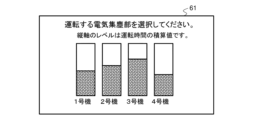
- FIG. 14 is a diagram showing another example of information displayed on the remote controller.
- the selection means 34 causes the display unit 61 of the remote controller 16 to display a message prompting the user to select the electrostatic precipitator to operate.
- FIG. 10 shows a case in which the selection means 34 causes the display unit 61 of the remote controller 16 to display, as selection auxiliary information, information showing the accumulated operating time of the electrostatic precipitator units 41-1 to 41-4 in the form of a bar graph.
- Unit 1 refers to electrostatic precipitator unit 41-1
- Unit 2 refers to electrostatic precipitator unit 41-2
- Unit 3 refers to electrostatic precipitator unit 41-3
- Unit 4 refers to electrostatic precipitator unit 41-4.
- the shorter the accumulated operating time the higher the discharge capacity and the longer the lifespan of the electrostatic precipitator unit.
- the user refers to the information shown in FIG. 14 displayed on the display unit 61 of the remote controller 16 and inputs an instruction to the remote controller 16 to select the electrostatic precipitator to be operated. At that time, since it is preferable for the electrostatic precipitator to have a high discharge capacity, the user selects the electrostatic precipitator to be operated from among the electrostatic precipitators 41-1 to 41-4, starting with the electrostatic precipitator that has been in operation for the shortest time.
- the electric dust collector applies a voltage to the charging section 44a to charge the dust contained in the airflow, causing it to discharge to the charging electrode 44.
- the electric dust collector becomes less capable of applying a voltage to the charging section 44a, and the effect of charging the dust decreases. Therefore, after a certain period of time from the start of use of the electric dust collector, it is necessary to replace the charging section 44a.
- users do not know how long each electric dust collector has been used. Therefore, after a certain period of time has passed since the start of use of the electric dust collectors 41-1 to 41-4, it was necessary to replace not only the electric dust collector with reduced discharge capacity, but all of the electric dust collectors 41-1 to 41-4. If the electric dust collectors continue to be used in a state where their discharge capacity has decreased, the dust sucked into the indoor unit 3 will return to the room without being captured.
- the remote controller 16 display the information shown in FIG. 14 on the display unit 61, the user can know the timing for replacing each of the electric dust collectors 41-1 to 41-4. This prevents the electric dust collectors from continuing to be used when their discharge capacity is low. Also, it is possible to replace only those electric dust collectors among the electric dust collectors 41-1 to 41-4 whose discharge capacity has decreased. As a result, it is possible to prevent the unnecessary disposal of electric dust collectors that still have a high discharge capacity. The same effect as above can be obtained even if, in step S5, the selection means 34 refers to the accumulated value of the operating time of each electric dust collector stored in the storage means 35 and selects the electric dust collector with the lowest accumulated value as the one to be operated.
- the selection means 34 switches the number of operating electrostatic precipitators in response to an instruction input by the user, but the method of determining the number of operating units is not limited to this case. For example, if an instruction to automatically set the number of operating units is input in advance from the user via the remote controller 16, the selection means 34 may select the number of operating units according to a predetermined criterion. Specifically, if an upper threshold for the total power consumption of the air conditioning device 1 is predetermined, the selection means 34 refers to the power consumption value of one electrostatic precipitator and selects the number of operating electrostatic precipitators so that the total power consumption of the air conditioning device 1 is equal to or lower than the upper threshold. In this case, it is possible to prevent the electricity fee for operating the air conditioning device 1 from exceeding the predetermined fee.
- the indoor unit 3 of the air conditioning device 1 of this embodiment 1 has a load side heat exchanger 9, an indoor blower 10 that draws in air from the space to be air-conditioned and sends the drawn-in air to the load side heat exchanger 9 to generate an airflow, a plurality of electric dust collectors 41-1 to 41-n that are provided upstream of the load side heat exchanger 9 in the direction of airflow and collect dust while in operation, and an indoor unit controller 22 that switches the number of electric dust collectors to be operated among the plurality of electric dust collectors 41-1 to 41-n.
- the number of electric dust collectors to be operated among the multiple electric dust collectors 41-1 to 41-n can be switched. Therefore, by setting the number of electric dust collectors to be operated to the minimum number that corresponds to the installation environment of the indoor unit 3, power consumption can be reduced. Furthermore, the selection means 34 or the user selects the electric dust collector to be operated based on information on the accumulated operating time of the multiple electric dust collectors, so that the degree of wear of the multiple electric dust collectors can be equalized. As a result, the frequency of replacing replacement parts of the electric dust collectors can be reduced. Furthermore, by referring to the selection support information (for example, the information shown in FIG. 14) displayed on the display unit 61 of the remote controller 16, the user can know the timing of replacing the electric dust collector, and can prevent the electric dust collector from being used continuously in a state where the discharge capacity is low.
- the selection support information for example, the information shown in FIG. 14
- the dust collector control means 33 operates at least one electric dust collector, and the selection means 34 switches the number of electric dust collectors in operation in response to a user instruction.
- the selection means 34 switches the number of electric dust collectors in operation in response to a user instruction.
- Embodiment 2 the selection means 34 and storage means 35 described in the first embodiment are provided in a location separate from the air conditioning device 1.
- the same components as those described in the first embodiment are given the same reference numerals, and detailed descriptions thereof are omitted.
- descriptions of the same components and operations as those of the air conditioning device 1 described in the first embodiment are omitted.
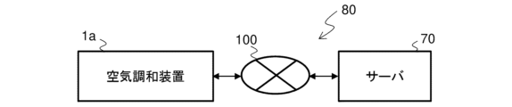
- FIG. 15 is a block diagram showing an example of the configuration of an air conditioning system according to the second embodiment.
- the air conditioning system 80 of the second embodiment has an air conditioning device 1a and a server 70.
- the air conditioning device 1a is connected to the server 70 via a network 100.
- the network 100 is, for example, the Internet.
- the air conditioning device 1a and the server 70 communicate according to a predetermined communication standard.
- the communication standard is, for example, TCP (Transmission Control Protocol)/IP (Internet Protocol).
- FIG. 16 is a functional block diagram showing an example of the configuration of the controller and server shown in FIG. 15.
- the air conditioning device 1a has an indoor unit controller 22a instead of the indoor unit controller 22 shown in FIG. 9.
- the indoor unit controller 22a does not have a selection means 34 and a storage means 35.
- the server 70 has a calculation means 71 and a storage means 35.
- the calculation means 71 has a selection means 34.
- the hardware of the calculation means 71 has the configuration described with reference to FIG. 11 or FIG. 12, for example.
- the storage means 35 is a HDD (Hard Disk Drive) or an SSD (Solid State Drive).
- the storage means 35 stores the integrated value of the operating time of each of the electric dust collectors 41-1 to 41-n. In this embodiment 2, the storage means 35 functions as an external storage of the air conditioning device 1a.
- the dust collection unit control means 33 calculates the operating time for each electric dust collection unit and transmits information on the calculated operating time to the selection means 34 of the server 70 via the remote controller 16 and the network.
- the selection means 34 receives information on the operating time of each electric dust collection unit from the dust collection unit control means 33, it adds it to the accumulated value of the operating time of each electric dust collection unit stored by the storage means 35. As a result, the accumulated value of the operating time stored in the storage means 35 is updated for each electric dust collection unit.
- the operation of the selection means 34 is similar to that described in embodiment 1, and therefore a detailed description of the operation of the air conditioning system 80 of embodiment 2 will be omitted.
- the remote controller 16 has been described as relaying communication between the controller 20 and the server 70, but communication between the controller 20 and the server 70 does not have to go through the remote controller 16.
- the server 70 is an example of an external information processing device, and the device in which the selection means 34 and the storage means 35 are provided is not limited to a server.
- the server 70 is provided with a selection means and a storage means, the storage means 35 stores the accumulated value of the operation time of each electric dust collector, and the selection means 34 performs an analysis to compare the magnitude of the accumulated value of the operation time of each electric dust collector. Therefore, there is no need to provide the air conditioner 1a with a storage device with a large memory capacity. In addition, the indoor unit controller 22a of the air conditioner 1a does not need to analyze the accumulated value of the operation time of each electric dust collector, so the load of calculation processing is reduced.
- the user, maintenance company, and manager of the air conditioning apparatus 1a can each refer to the information stored in the storage means 35 by connecting an information processing device such as a smartphone to the server 70 via the network 100.
- the storage means 35 is provided in the air conditioning apparatus 1.
- the maintenance company cannot refer to the information stored in the storage means 35 unless they carry an information processing terminal and go to the location where the air conditioning apparatus 1 is installed.
- the maintenance company can connect an information processing device to the server 70 via the network 100 and view the information stored in the storage means 35.
- the maintenance company can determine the state of each of the electric dust collectors 41-1 to 41-n from a location away from the installation site of the air conditioning device 1a.
- the instruction manual for the air conditioner describes the replacement period for the electric dust collector, but users often do not replace the parts of the electric dust collector themselves.
- a maintenance company can determine which electric dust collector needs to be replaced by referring to the accumulated operating time of each electric dust collector 41-1 to 41-n from a location away from the installation site of the air conditioner 1a. Therefore, the maintenance company can go to the installation site of the air conditioner 1a to replace the electric dust collector parts even if there is no request for part replacement from the user. As a result, it is possible to prevent the user from continuing to use the electric dust collector with low discharge capacity without knowing that the discharge capacity of the electric dust collector has decreased.
- 1, 1a air conditioning device 2 outdoor unit, 3 indoor unit, 4 compressor, 5 four-way valve, 6 outdoor blower, 7 heat source side heat exchanger, 8 expansion valve, 9 load side heat exchanger, 10 indoor blower, 11 dust collection module, 12 room temperature sensor, 13 refrigerant piping, 15 refrigerant circuit, 16 remote controller, 20 controller, 21 outdoor unit controller, 22, 22a indoor unit controller, 31 refrigeration cycle control means, 32 indoor fan control means, 33 dust collection section control means, 34 selection means, 35 storage means, 36 type , 41-1 to 41-n electric dust collecting unit, 42 high voltage power supply, 43 dust collecting unit, 44 charged electrode, 44a charged unit, 44b counter electrode, 45 dust collecting electrode, 51, 52 signal line, 53 housing, 54 intermediate unit, 55 decorative panel, 56 intake port, 57 filter, 58 exhaust port, 61 display unit, 62 operation unit, 65 blade, 66 fan motor, 70 server, 71 calculation means, 80 air conditioning system, 90 processing circuit, 91 processor, 92 memory, 93 bus, 100 network, PLc ceiling.
Landscapes
- Engineering & Computer Science (AREA)
- Chemical & Material Sciences (AREA)
- Combustion & Propulsion (AREA)
- Mechanical Engineering (AREA)
- General Engineering & Computer Science (AREA)
- Air Conditioning Control Device (AREA)
Abstract
空気調和装置の室内機は、負荷側熱交換器と、空調対象空間から空気を吸い込み、吸い込んだ空気を負荷側熱交換器に送出することで気流を発生する送風機と、気流の流通方向において負荷側熱交換器よりも上流に設けられ、運転している状態で集塵する複数の電気集塵部と、複数の電気集塵部のうち、運転させる電気集塵部の台数を切り替えるコントローラと、を有する。
Description
本開示は、空調対象空間の空気を調和する空気調和装置の室内機および空気調和システムに関する。
従来、室内の空気を清浄にするための空気清浄ユニットを備えた空気調和機が知られている(例えば、特許文献1参照)。空気清浄ユニットは、空気中に浮遊する捕捉対象物を帯電させる荷電部と、荷電部により帯電した捕捉対象物を捕捉して取り除く捕捉部とを有する。荷電部には、複数の荷電モジュールが設けられている。
特許文献1の空気調和機は、複数の荷電モジュールに対して、風速の違いによって荷電モジュールに印加する電圧を変える制御を行っている。具体的には、風速の遅いところに配置された荷電モジュールの印加電圧を下げることで、消費電力量の低減を図っている。
しかし、特許文献1に開示された空気調和機は、風速の遅いところに配置された荷電モジュールの印加電圧を下げているが、風速の遅いところに配置された荷電モジュールも放電させているため、消費電力量の抑制効果が十分ではなかった。
本開示は、上記のような課題を解決するためになされたもので、空調対象空間の塵埃を捕集しながら、消費電力量を抑制できる空気調和装置の室内機および空気調和システムを提供するものである。
本開示に係る空気調和装置の室内機は、負荷側熱交換器と、空調対象空間から空気を吸い込み、吸い込んだ空気を前記負荷側熱交換器に送出することで気流を発生する送風機と、前記気流の流通方向において前記負荷側熱交換器よりも上流に設けられ、運転している状態で集塵する複数の電気集塵部と、前記複数の電気集塵部のうち、運転させる前記電気集塵部の台数を切り替えるコントローラと、を有するものである。
本開示に係る空気調和システムは、負荷側熱交換器、空調対象空間から空気を吸い込み、吸い込んだ空気を前記負荷側熱交換器に送出することで気流を発生する送風機、および前記気流の流通方向において前記負荷側熱交換器よりも上流に設けられ、運転している状態で集塵する複数の電気集塵部を備えた室内機を含む空気調和装置と、前記複数の電気集塵部のうち、運転させる前記電気集塵部の台数を切り替える選択手段と、を有するものである。
本開示によれば、複数の電気集塵部のうち、運転する電気集塵部の台数を切り替えることができるため、電気集塵部の運転台数を室内機の設置環境に対応した最低限の台数にすることで、消費電力を抑制することができる。
本開示の空気調和装置の室内機および空気調和システムの実施の形態を、図を参照して説明する。一部の図においては、説明の便宜上、室内機が設置される3次元空間において、X軸、Y軸およびZ軸の3つの方向を定義している。
実施の形態1.
本実施の形態1の空気調和装置の構成を説明する。図1は、実施の形態1に係る空気調和装置の一構成例を示す冷媒回路図である。空気調和装置1は、室外機2と、室内機3と、リモートコントローラ16とを有する。室外機2は、圧縮機4、四方弁5、室外送風機6、熱源側熱交換器7、膨張弁8および室外機コントローラ21を有する。室内機3は、負荷側熱交換器9、室内送風機10、集塵モジュール11および室内機コントローラ22を有する。圧縮機4、熱源側熱交換器7、膨張弁8および負荷側熱交換器9が冷媒配管13で接続され、冷媒回路15が構成される。
本実施の形態1の空気調和装置の構成を説明する。図1は、実施の形態1に係る空気調和装置の一構成例を示す冷媒回路図である。空気調和装置1は、室外機2と、室内機3と、リモートコントローラ16とを有する。室外機2は、圧縮機4、四方弁5、室外送風機6、熱源側熱交換器7、膨張弁8および室外機コントローラ21を有する。室内機3は、負荷側熱交換器9、室内送風機10、集塵モジュール11および室内機コントローラ22を有する。圧縮機4、熱源側熱交換器7、膨張弁8および負荷側熱交換器9が冷媒配管13で接続され、冷媒回路15が構成される。
室外機コントローラ21および室内機コントローラ22は、信号線51を介して接続され、コントローラ20を構成する。室内機コントローラ22は信号線52を介してリモートコントローラ16と接続される。室内機3には、空調対象空間の空気の温度である室温Trを検出する室温センサ12が設けられている。室外機コントローラ21は、図に示さない信号線を介して、圧縮機4、四方弁5、室外送風機6および膨張弁8のそれぞれと接続される。室内機コントローラ22は、図に示さない信号線を介して、室内送風機10、集塵モジュール11および室温センサ12のそれぞれと接続される。室温センサ12は、検出する室温Trの情報を室内機コントローラ22に送信する。
四方弁5は、冷媒回路15を循環する冷媒の流通方向を切り替える。空気調和装置1の室内機3の運転モードが冷房運転の場合、図1に示す四方弁5内は実線に示す流路となる。室内機3の運転モードが暖房運転の場合、図1に示す四方弁5内は破線に示す流路となる。圧縮機4は、低温および低圧の冷媒を吸入し、吸入した冷媒を圧縮して吐出する。圧縮機4は、例えば、運転周波数を変更することで容量を調節することができるインバータ圧縮機である。
室外送風機6は、外気を吸い込み、吸い込んだ外気を熱源側熱交換器7に送出する。室外送風機6は、例えば、プロペラファンである。室内送風機10は、空調対象空間から空気を吸い込み、吸い込んだ空気を負荷側熱交換器9に送出する。室内送風機10は、例えば、遠心ファンである。
熱源側熱交換器7は、外気と冷媒とを熱交換させる熱交換器である。室内機3の運転モードが冷房運転の場合、熱源側熱交換器7は凝縮器として機能する。室内機3の運転モードが暖房運転の場合、熱源側熱交換器7は蒸発器として機能する。負荷側熱交換器9は、室内の空気と冷媒とを熱交換させる熱交換器である。室内機3の運転モードが冷房運転の場合、負荷側熱交換器9は蒸発器として機能する。室内機3の運転モードが暖房運転の場合、負荷側熱交換器9は凝縮器として機能する。熱源側熱交換器7および負荷側熱交換器9は、例えば、伝熱管および複数の放熱フィンを有するフィンアンドチューブ型熱交換器である。膨張弁8は、熱源側熱交換器7および負荷側熱交換器9から流入する液冷媒を減圧して膨張させる。膨張弁8は、例えば、電子膨張弁である。
図2は、実施の形態1に係る空気調和装置の室内機の設置例を示す側面図である。図2に示すように、室内機3は、部屋の天井PLcに埋め込むことができる天井埋め込み型の室内機である。本実施の形態1においては、室内機3が天井埋め込み型の場合で説明するが、室内機3は、壁に取り付けられる壁掛型であってもよく、床面に設置される床置き型であってもよい。
リモートコントローラ16は、ユーザに情報を表示する表示部61と、ユーザが空気調和装置1に指示を入力するための操作部62とを有する。表示部61は、例えば、液晶ディスプレイである。操作部62は、複数のボタンで構成される。操作部62は、タッチパネルであってもよい。
図3は、図2に示した室内機の一構成例を示す展開図である。図4は、図2に示した室内機の平面図である。室内機3は、空調対象空間である部屋に面する化粧パネル55と、化粧パネル55の上に積み重ねられる中間ユニット54と、中間ユニット54の上に積み重ねられる筐体53とを有する。筐体53は、図1に示した負荷側熱交換器9、室内送風機10、室温センサ12および室内機コントローラ22を収容する。中間ユニット54は、集塵モジュール11を収容する。
化粧パネル55は、中央に設けられた吸込口56と、吸込口56の周囲に設けられた4つの吹出口58とを有する。吸込口56には、部屋から吸い込まれる塵埃を捕集するフィルタ57が設けられている。室内機3は、4方向に吹出口58が形成された4方向カセット型の室内機である。室内機3は、2方向に吹出口58が形成された2方向カセット型の室内機であってもよい。
図5は、図3に示した中間ユニットの外観斜視図である。集塵モジュール11は、複数の電気集塵部41-1~41-nを有する。nは2以上の任意の整数である。本実施の形態1においては、図5に示すように、n=4の場合で説明するが、nの値は4に限らない。電気集塵部41-1~41-4は、XY平面に平行に中間ユニット54に配置されている。電気集塵部41-1~41-4のそれぞれは、図4に示したフィルタ57が捕集できない塵埃を捕集する役目を果たす。塵埃とは、例えば、空気中に浮遊する埃または花粉である。
図6は、図4に示した室内機についてA-A線部分で切ったときの断面模式図である。室内送風機10は、羽根65と、回転軸を介して羽根65を回転させるファンモータ66とを有する。図6において、室内送風機10が部屋から吸い込んだ空気を負荷側熱交換器9に送出することで発生する空気の流れである気流の流通方向を矢印で示す。図6に示すように、電気集塵部41-1~41-4は、気流の流通方向において負荷側熱交換器9よりも上流に設けられている。
室内送風機10が運転を開始すると、室内の空気は、吸込口56およびフィルタ57を介して室内機3に吸い込まれる。室内機3に吸い込まれた空気は、4つの電気集塵部41-1~41-4のいずれかを経由して、負荷側熱交換器9に到達する。負荷側熱交換器9に到達した空気は、負荷側熱交換器9において冷媒と熱交換を行った後、4つの吹出口58に分流して部屋に戻る。電気集塵部41-k(kは1~nの任意の整数)が運転している場合、電気集塵部41-kを流通する塵埃が電気集塵部41-kに捕集される。一方、電気集塵部41-kが運転していない場合、電気集塵部41-kを流通する塵埃は、電気集塵部41-kに捕集されず、再び、部屋に戻ってしまう。
次に、電気集塵部41-1~41-nの構成を説明する。電気集塵部41-1~41-nはいずれも同一の構成であるため、ここでは、電気集塵部41-1の構成を説明する。
図7は、図5に示した電気集塵部の外観斜視図である。図8は、図7に示した電気集塵部の一構成例を示すブロック図である。図8に示す矢印は、室内送風機10の運転によって発生する気流の流通方向を示す。電気集塵部41-1は、商用電源(図示せず)から供給される電気の電圧を昇圧して高電圧を生成する高圧電源42と、高電圧によって塵埃を帯電させて捕集する集塵部43とを有する。電気集塵部41-1~41-4のそれぞれの集塵部43は、個別に高圧電源42から高電圧が印加される。集塵部43は、帯電電極44と、集塵電極45とを有する。
帯電電極44は、高電圧が印加される荷電部44aと、荷電部44aに対向して配置される対向電極44bとを有する。帯電電極44は、荷電部44aと対向電極44bとの間で放電させることで、荷電部44aと対向電極44bとの間を流通する気流中の塵埃を帯電させる。集塵電極45は、気流の流通方向の下流に配置される。集塵電極45は、気流の流通方向に直交する面に平行に配置され、メッシュ状の金属材で構成される。集塵電極45は、接地されている。集塵電極45は、帯電した塵埃を捕集する。
次に、コントローラ20の構成を説明する。図9は、図1に示したコントローラの一構成例を示す機能ブロック図である。室外機コントローラ21および室内機コントローラ22のそれぞれは、例えば、マイクロコンピュータである。室内機コントローラ22は、室温センサ12から室温Trの情報を受信すると、室温Trの情報を、信号線51を介して室外機コントローラ21に送信する。また、室内機コントローラ22は、リモートコントローラ16からユーザによる指示が入力されると、入力された指示の情報を、信号線51を介して室外機コントローラ21に送信する。
室外機コントローラ21は、冷凍サイクル制御手段31を有する。冷凍サイクル制御手段31は、圧縮機4、四方弁5、膨張弁8および室外送風機6を制御する。具体的には、冷凍サイクル制御手段31は、リモートコントローラ16を介して、ユーザによって空気調和装置1の運転モードおよび運転開始の指示が入力されると、指示された運転モードに対応して四方弁5内の冷媒の流通方向を切り替える。また、冷凍サイクル制御手段31は、室温センサ12によって検出される室温Trが設定温度Tsに近づくように、圧縮機4の運転周波数、膨張弁8の開度および室外送風機6の回転数を制御する。設定温度Tsは、リモートコントローラ16を介して、ユーザによって冷凍サイクル制御手段31に入力される。
室内機コントローラ22は、室内ファン制御手段32と、集塵部制御手段33と、選択手段34と、記憶手段35と、時間を計測するタイマー36とを有する。室内ファン制御手段32は、リモートコントローラ16を介して、ユーザによって風量の指示が入力されると、指示された風量に対応して室内送風機10の回転数を制御する。室内ファン制御手段32は、リモートコントローラ16を介して、ユーザによって空気調和装置1の運転開始の指示が入力されると、室内送風機10を起動し、運転開始信号を集塵部制御手段33に送信する。
記憶手段35は、電気集塵部毎に運転時間の積算値を記憶する。記憶手段35は、1台の電気集塵部の消費電力の情報を記憶する。記憶手段35は、予め決められた期間Dpの電気集塵部41-1~41-4の消費電力量を記憶する。期間Dpは、例えば、直近の数時間、直近の1日、直近の1週間、直近の1カ月、または直近の半年などである。
記憶手段35が記憶する1台の電気集塵部の消費電力の値は、電気集塵部の仕様で決められた値であってもよく、空気調和装置1の運転中に算出されるものであってもよい。例えば、空気調和装置1の運転中に、電気集塵部41-1が運転している状態の空気調和装置1の消費電力から電気集塵部41-1が運転していない状態の空気調和装置1の消費電力を減算することで、1台の電気集塵部41-1の消費電力が算出される。
選択手段34は、空気調和装置1が運転を開始した後、電気集塵部の運転台数がユーザによって入力されると、運転台数の情報を集塵部制御手段33に送信する。選択手段34は、空気調和装置1が運転を開始したとき、電気集塵部の運転台数の入力を、リモートコントローラ16を介して、ユーザに促してもよい。また、選択手段34は、空気調和装置1が運転を開始したとき、記憶手段35が記憶する情報を参照し、ユーザに対して運転台数の選択を補助するための情報である選択補助情報を表示させてもよい。選択補助情報は、例えば、1台の電気集塵部41-kの消費電力の情報を含む。
図10は、リモートコントローラに表示される情報の一例を示す図である。図10に示すように、選択手段34は、運転する電気集塵部の台数の入力をユーザに促すメッセージをリモートコントローラ16の表示部61に表示させる。図10は、選択手段34が、選択補助情報として、1台の電気集塵部の消費電力の情報と、直近の1週間の電気集塵部の状況に関する情報とをリモートコントローラ16の表示部61に表示させる場合を示す。
また、選択手段34は、複数の電気集塵部41-1~41-4のうち、ユーザによって指示された運転台数に対して、予め決められた基準にしたがって、運転対象の電気集塵部を選択してもよい。例えば、運転対象の電気集塵部を自動設定する旨の指示が、リモートコントローラ16を介してユーザから予め入力されている場合が考えられる。この場合、例えば、選択手段34は、記憶手段35が記憶する情報を参照し、電気集塵部41-1~41-4のうち、運転時間の積算値が少ない電気集塵部から運転台数の電気集塵部を選択する。この場合、選択手段34は、選択した電気集塵部の情報を含む指定情報を集塵部制御手段33に送信する。
集塵部制御手段33は、各電気集塵部の起動および停止を制御する。具体的には、電気集塵部41-kを起動する場合、集塵部制御手段33は、電気集塵部41-kに対応する高圧電源42への入力電圧の供給を開始する。電気集塵部41-kを停止する場合、集塵部制御手段33は、電気集塵部41-kに対応する高圧電源42への入力電圧の供給を遮断する。集塵部制御手段33は、運転開始信号を室内ファン制御手段32から受信すると、1台の電気集塵部を起動する。集塵部制御手段33は、電気集塵部の運転台数の情報を選択手段34から受信すると、受信した運転台数の電気集塵部の運転を開始させる。その際、集塵部制御手段33は、運転対象の電気集塵部を電気集塵部41-1~41-4からランダムに選択してもよく、ユーザの指示にしたがって選択してもよい。集塵部制御手段33は、指定情報を選択手段34から受信する場合、指定情報にしたがって、起動する電気集塵部を選択する。
また、集塵部制御手段33は、空気調和装置1の運転開始から運転停止までの間、タイマー36の計測時間を参照し、電気集塵部毎に運転時間を算出する。そして、集塵部制御手段33は、電気集塵部毎に算出した運転時間を、選択手段34を介して、記憶手段35によって記憶される電気集塵部の運転時間の積算値に加算する。これにより、記憶手段35が記憶する運転時間の積算値が電気集塵部毎に更新される。なお、電気集塵部毎の運転時間の積算値の更新は、選択手段34によって実行されてもよい。
ここで、図9を参照して説明したコントローラ20のハードウェアの一例を説明する。図11は、図9に示したコントローラの一構成例を示すハードウェア構成図である。コントローラ20の各種機能がハードウェアで実行される場合、図9に示したコントローラ20は、図11に示すように、処理回路90で構成される。図9に示した、冷凍サイクル制御手段31、室内ファン制御手段32、集塵部制御手段33、選択手段34、記憶手段35およびタイマー36の各機能は、処理回路90により実現される。
各機能がハードウェアで実行される場合、処理回路90は、例えば、単一回路、複合回路、プログラム化したプロセッサ、並列プログラム化したプロセッサ、ASIC(Application Specific Integrated Circuit)、FPGA(Field-Programmable Gate Array)、または、これらを組み合わせたものに該当する。冷凍サイクル制御手段31、室内ファン制御手段32、集塵部制御手段33、選択手段34、記憶手段35およびタイマー36の各手段の機能のそれぞれを別々の処理回路90で実現してもよい。また、冷凍サイクル制御手段31、室内ファン制御手段32、集塵部制御手段33、選択手段34、記憶手段35およびタイマー36の各手段の機能を1つの処理回路90で実現してもよい。
また、図9に示したコントローラ20の別のハードウェアの一例を説明する。図12は、図9に示したコントローラの別の構成例を示すハードウェア構成図である。コントローラ20の各種機能がソフトウェアで実行される場合、図9に示したコントローラ20は、図12に示すように、CPU(Central Processing Unit)等のプロセッサ91およびメモリ92で構成される。冷凍サイクル制御手段31、室内ファン制御手段32、集塵部制御手段33、選択手段34、記憶手段35およびタイマー36の各機能は、プロセッサ91およびメモリ92により実現される。図12は、プロセッサ91およびメモリ92が互いにバス93を介して通信可能に接続されることを示している。
各機能がソフトウェアで実行される場合、冷凍サイクル制御手段31、室内ファン制御手段32、集塵部制御手段33、選択手段34、記憶手段35およびタイマー36の機能は、ソフトウェア、ファームウェア、またはソフトウェアとファームウェアとの組み合わせにより実現される。ソフトウェアおよびファームウェアは、プログラムとして記述され、メモリ92に格納される。プロセッサ91は、メモリ92に記憶されたプログラムを読み出して実行することにより、各手段の機能を実現する。
メモリ92として、例えば、ROM(Read Only Memory)、フラッシュメモリ、EPROM(Erasable and Programmable ROM)およびEEPROM(Electrically Erasable and Programmable ROM)等の不揮発性の半導体メモリが用いられる。また、メモリ92として、RAM(Random Access Memory)の揮発性の半導体メモリが用いられてもよい。さらに、メモリ92として、磁気ディスク、フレキシブルディスク、光ディスク、CD(Compact Disc)、MD(Mini Disc)およびDVD(Digital Versatile Disc)等の着脱可能な記録媒体が用いられてもよい。
なお、図11および図12を参照して、コントローラ20のハードウェア構成例を説明したが、室外機コントローラ21および室内機コントローラ22のそれぞれが図11または図12に示したハードウェア構成であってもよい。また、コントローラ20の機能が室外機コントローラ21と室内機コントローラ22とに分割される場合で説明したが、分割されなくてもよい。この場合、コントローラ20は、室外機2または室内機3のいずれかに設けられていてもよく、室外機2および室内機3とは別の場所に設けられていてもよい。
次に、本実施の形態1の空気調和装置1の室内機3の動作を説明する。図13は、実施の形態1に係る空気調和装置の室内機の動作手順を示すフロー図である。
ステップS1において、コントローラ20は、空気調和装置1の運転開始の指示が入力されるか判定する。空気調和装置1の運転開始の指示が入力される場合(ステップS1:Yesの場合)、コントローラ20は空気調和装置1の運転を開始する(ステップS2)。具体的には、冷凍サイクル制御手段31は圧縮機4、四方弁5、膨張弁8および室外送風機6の制御を開始する。室内ファン制御手段32は、室内送風機10の運転を開始し、運転開始信号を集塵部制御手段33に送信する。
集塵部制御手段33は、室内ファン制御手段32から運転開始信号を受信すると、電気集塵部41-1~41-nのうち、1台の電気集塵部の運転を開始する(ステップS3)。その際、例えば、集塵部制御手段33は、記憶手段35が記憶する情報を参照し、運転時間の積算時間が最も少ない電気集塵部を運転対象に選択する。
空気調和装置1の運転が開始すると、選択手段34は、電気集塵部の運転台数jが入力されたか判定する(ステップS4)。ステップS4の判定の結果、電気集塵部の運転台数jが入力された場合(ステップS4:Yesの場合)、選択手段34は、運転台数jの情報を集塵部制御手段33に送信する。一方、ステップS4の判定の結果、電気集塵部の運転台数jが入力されなかった場合(ステップS4:Noの場合)、選択手段34は、運転台数jが変更されなかった旨の情報を集塵部制御手段33に送信し、ステップS6の処理に進む。
集塵部制御手段33は、運転台数jの情報を選択手段34から受信すると、運転台数jに対応する台数の電気集塵部の運転を開始する(ステップS5)。リモートコントローラ16を介してユーザから空気調和装置1の運転停止の指示が入力されるまで、運転台数jの電気集塵部は放電を続ける。その後、ステップS6において、コントローラ20は、空気調和装置1の運転停止の指示が入力されたか判定する。ステップS6の判定の結果、空気調和装置1の運転停止の指示が入力されない場合(ステップS6:Noの場合)、コントローラ20は、ステップS4の処理に戻る。ステップS4の処理において、新たな運転台数jが入力されると、選択手段34は、新たに入力された運転台数jの情報を集塵部制御手段33に送信する。これにより、ステップS5において、運転する電気集塵部の台数が新たに入力された運転台数jに切り替わる。
一方、ステップS6の判定の結果、空気調和装置1の運転停止の指示が入力された場合(ステップS6:Yesの場合)、コントローラ20は空気調和装置1の運転を停止する(ステップS7)。具体的には、冷凍サイクル制御手段31は圧縮機4および室外送風機6を停止する。室内ファン制御手段32は室内送風機10を停止する。集塵部制御手段33は、運転していた運転台数jの電気集塵部を停止する。そして、集塵部制御手段33は、運転していた運転台数jの電気集塵部毎に運転時間を記憶手段35に記憶させる(ステップS8)。
このようにして、選択手段34は、リモートコントローラ16を介してユーザによって指示された運転台数に対応して、電気集塵部の運転台数を切り替える。ステップS4において、選択手段34は、図10に示した画像をリモートコントローラ16の表示部61に表示させてもよい。この場合、ユーザは、図10に示した画像を参照することで、電気集塵部の消費電力量が多いと考えると、運転する電気集塵部の数を減らす。これにより、電気集塵部にかかる電気料金が高くなることを回避できる。一方、杉などの花粉が多く飛散する時期に、ユーザは、図10に示した画像を参照し、表示された消費電力量が電気料金への影響が小さいと考える場合、電気集塵部の運転台数を増やすことができる。この場合、室内の空気環境がユーザにとってより快適になる。
また、ステップS8において、集塵部制御手段33は、運転していた運転台数jの電気集塵部の消費電力量をリモートコントローラ16の表示部61に表示させてもよい。この場合、ユーザは、空気調和装置1の停止直後に、電気集塵部の消費電力量を知ることができるので、次回、空気調和装置1を運転させる際、電気集塵部の運転台数の増減を判断しやすくなる。
また、ステップS4において、選択手段34は、図10に示した選択補助情報とは別の選択補助情報をリモートコントローラ16に表示させてもよい。図14は、リモートコントローラに表示される情報の別の例を示す図である。
図14に示すように、選択手段34は、運転する電気集塵部の選択をユーザに促すメッセージをリモートコントローラ16の表示部61に表示させる。図10は、選択手段34が、選択補助情報として、電気集塵部41-1~41-4の運転時間の積算値を棒グラフで示す情報をリモートコントローラ16の表示部61に表示させる場合を示す。図10において、1号機は電気集塵部41-1を意味し、2号機は電気集塵部41-2を意味し、3号機は電気集塵部41-3を意味し、4号機は電気集塵部41-4を意味する。運転時間の積算時間が少ないほど、放電能力が高く、電気集塵部の寿命が長いことを意味すする。
ユーザは、リモートコントローラ16の表示部61が表示する図14に示す情報を参照し、運転対象の電気集塵部を選択する指示をリモートコントローラ16に入力する。その際、ユーザは、放電能力が高い方がよいので、電気集塵部41-1~41-4のうち、運転時間の少ない電気集塵部から運転させる電気集塵部を選択する。
電気集塵部は、運転中、気流に含まれる塵埃を帯電させるために、荷電部44aに電圧を印加することで帯電電極44に放電させる。放電時間が長くなると、電気集塵部は荷電部44aに電圧を印加する能力が低くなり、塵埃を帯電させる効果が低下する。そのため、電気集塵部の使用開始から一定期間すると荷電部44aを交換する必要がある。従来、ユーザは、どの電気集塵部がどのくらい使用されているかわからない。そのため、電気集塵部41-1~41-4の使用開始から一定期間が経過すると、放電能力が低下した電気集塵部だけでなく、電気集塵部41-1~41-4の全てを交換する必要があった。放電能力が低下した状態で電気集塵部の使用を継続すると、室内機3に吸い込まれた塵埃が捕集されることなく、再び、室内に戻ってしまう。
これに対して、リモートコントローラ16が図14に示した情報を表示部61に表示することで、ユーザは、電気集塵部41-1~41-4の各電気集塵部の交換のタイミングを知ることができる。そのため、放電能力が低い状態で電気集塵部の使用を継続してしまうことを防げる。また、電気集塵部41-1~41-4のうち、放電能力が低下した電気集塵部だけを交換することができる。その結果、まだ放電能力が高い電気集塵部を無駄に廃棄してしまうことを防ぐことができる。ステップS5において、選択手段34が、記憶手段35が記憶する各電気集塵部の運転時間の積算値を参照し、積算値の少ない電気集塵部を運転対象に選択する場合しても、上記と同様な効果が得られる。
なお、本実施の形態1においては、ユーザから入力される指示に対応して、選択手段34が電気集塵部の運転台数を切り替える場合で説明したが、運転台数の決定方法はこの場合に限らない。例えば、運転台数を自動設定する旨の指示がリモートコントローラ16を介してユーザから予め入力されている場合、選択手段34は、予め決められた基準にしたがって運転台数を選択してもよい。具体的には、空気調和装置1の全体の消費電力の上限閾値が予め決められている場合、選択手段34は、空気調和装置1の全体の消費電力が上限閾値以下になるように、1台の電気集塵部の消費電力の値を参照し、電気集塵部の運転台数を選択する。この場合、空気調和装置1の運転にかかる電気料金が、決められた料金より大きくなることを防ぐことができる。
本実施の形態1の空気調和装置1の室内機3は、負荷側熱交換器9と、空調対象空間から空気を吸い込み、吸い込んだ空気を負荷側熱交換器9に送出することで気流を発生する室内送風機10と、気流の流通方向において負荷側熱交換器9よりも上流に設けられ、運転している状態で集塵する複数の電気集塵部41-1~41-nと、複数の電気集塵部41-1~41-nのうち、運転させる電気集塵部の台数を切り替える室内機コントローラ22とを有する。
本実施の形態1によれば、複数の電気集塵部41-1~41-nのうち、運転する電気集塵部の台数を切り替えることができる。そのため、電気集塵部の運転台数を室内機3の設置環境に対応した最低限の台数にすることで、消費電力を抑制することができる。また、複数の電気集塵部の運転時間の積算時間の情報を基に、選択手段34またはユーザが運転対象の電気集塵部を選択することで、複数の電気集塵部の消耗度を均等化することができる。その結果、電気集塵部の交換部品の交換頻度を低減することができる。さらに、ユーザは、リモートコントローラ16の表示部61に表示される選択補助情報(例えば、図14が示す情報)を参照することで、電気集塵部の交換のタイミングを知ることができ、放電能力が低い状態で電気集塵部の使用を継続してしまうことを防げる。
また、本実施の形態1によれば、空気調和装置1の運転中、集塵部制御手段33が少なくとも1台の電気集塵部が運転させ、選択手段34がユーザの指示に対応して電気集塵部の運転台数を切り替える。1台以上の電気集塵部が運転することで、室内の空気中に浮遊するカビ菌および細菌を殺菌し、室内の空気中に浮遊するウイルスおよびアレルゲンを不活性化することができる。
実施の形態2.
本実施の形態2は、実施の形態1で説明した選択手段34および記憶手段35が空気調和装置1とは別の場所に設けられたものである。本実施の形態2においては、実施の形態1で説明した構成と同一の構成に同一の符号を付し、その詳細な説明を省略する。本実施の形態2においては、実施の形態1で説明した空気調和装置1と同様な構成および動作の説明を省略する。
本実施の形態2は、実施の形態1で説明した選択手段34および記憶手段35が空気調和装置1とは別の場所に設けられたものである。本実施の形態2においては、実施の形態1で説明した構成と同一の構成に同一の符号を付し、その詳細な説明を省略する。本実施の形態2においては、実施の形態1で説明した空気調和装置1と同様な構成および動作の説明を省略する。
本実施の形態2の空気調和システムの構成を説明する。図15は、実施の形態2に係る空気調和システムの一構成例を示すブロック図である。図15に示すように、本実施の形態2の空気調和システム80は、空気調和装置1aと、サーバ70とを有する。空気調和装置1aは、ネットワーク100を介してサーバ70と接続される。ネットワーク100は、例えば、インターネットである。空気調和装置1aおよびサーバ70は、予め決められた通信規格にしたがって通信を行う。通信規格は、例えば、TCP(Transmission Control Protocol)/IP(Internet Protocol)である。
図16は、図15に示したコントローラおよびサーバの一構成例を示す機能ブロック図である。空気調和装置1aは、図9に示した室内機コントローラ22の代わりに、室内機コントローラ22aを有する。室内機コントローラ22aは、室内機コントローラ22と比較すると、選択手段34および記憶手段35を有していない構成である。
サーバ70は、演算手段71と、記憶手段35とを有する。演算手段71は選択手段34を有する。演算手段71のハードウェアは、例えば、図11または図12を参照して説明した構成である。記憶手段35は、HDD(Hard Disk Drive)またはSSD(Solide State Drive)である。記憶手段35は、電気集塵部41-1~41-nの各電気集塵部の運転時間の積算値を記憶する。本実施の形態2においては、記憶手段35は、空気調和装置1aの外部のストレージとして機能する。
集塵部制御手段33は、電気集塵部毎に運転時間を算出し、算出した運転時間の情報をリモートコントローラ16およびネットワークを介してサーバ70の選択手段34に送信する。選択手段34は、各電気集塵部の運転時間の情報を集塵部制御手段33から受信すると、記憶手段35によって記憶される各電気集塵部の運転時間の積算値に加算する。これにより、記憶手段35が記憶する運転時間の積算値が電気集塵部毎に更新される。
なお、選択手段34の動作は実施の形態1で説明した動作と同様になるため、本実施の形態2の空気調和システム80の動作について、その詳細な説明を省略する。また、本実施の形態2においては、リモートコントローラ16がコントローラ20とサーバ70との通信を中継する役目を果たす場合で説明したが、コントローラ20とサーバ70との通信はリモートコントローラ16を介さなくてもよい。また、サーバ70は、外部に設けられる情報処理装置の一例であり、選択手段34および記憶手段35が設けられる装置はサーバに限らない。
本実施の形態2によれば、サーバ70に選択手段および記憶手段が設けられ、記憶手段35が各電気集塵部の運転時間の積算値を記憶し、選択手段34が各電気集塵部の運転時間の積算値の大小を比較する分析を行う。そのため、空気調和装置1aに大きな記憶容量のストレージを設ける必要がない。また、空気調和装置1aの室内機コントローラ22aは、各電気集塵部の運転時間の積算値を分析する必要がないので、演算処理の負荷が軽減する。
また、本実施の形態2は、空気調和装置1aのユーザ、メンテナンス業者およびの管理者のそれぞれは、スマートホン等の情報処理装置を、ネットワーク100を介してサーバ70に通信接続させれば、記憶手段35が記憶する情報を参照できる。実施の形態1で説明した空気調和装置1の場合、記憶手段35が空気調和装置1に設けられている。この場合、メンテナンス業者は、情報処理端末を携帯して空気調和装置1が設置された場所に行かなければ、記憶手段35が記憶する情報を参照することができない。
これに対して、本実施の形態2によれば、上述したように、メンテナンス業者は、ネットワーク100を介して情報処理装置をサーバ70に通信接続させ、記憶手段35が記憶する情報を見られる。この場合、メンテナンス業者は、空気調和装置1aの設置場所から離れたところから、電気集塵部41-1~41-nの各電気集塵部の状態を判定できる。
通常、空気調和装置の取り扱い説明書には、電気集塵部の交換周期が記載されているが、ユーザが自ら電気集塵部の部品を交換しないことが多い。メンテナンス業者は、空気調和装置1aの設置場所から離れたところから、電気集塵部41-1~41-nの各電気集塵部の運転時間の積算値を参照することで、交換が必要な電気集塵部を判定することができる。そのため、メンテナンス業者は、ユーザから部品交換の依頼がなくても、空気調和装置1aの設置場所に電気集塵部の部品交換に行くことができる。その結果、ユーザが、電気集塵部の放電能力が低下していることを知らずに、放電能力が低い状態で電気集塵部の使用を継続してしまうことを防ぐことができる。
1、1a 空気調和装置、2 室外機、3 室内機、4 圧縮機、5 四方弁、6 室外送風機、7 熱源側熱交換器、8 膨張弁、9 負荷側熱交換器、10 室内送風機、11 集塵モジュール、12 室温センサ、13 冷媒配管、15 冷媒回路、16 リモートコントローラ、20 コントローラ、21 室外機コントローラ、22、22a 室内機コントローラ、31 冷凍サイクル制御手段、32 室内ファン制御手段、33 集塵部制御手段、34 選択手段、35 記憶手段、36 タイマー、41-1~41-n 電気集塵部、42 高圧電源、43 集塵部、44 帯電電極、44a 荷電部、44b 対向電極、45 集塵電極、51、52 信号線、53 筐体、54 中間ユニット、55 化粧パネル、56 吸込口、57 フィルタ、58 吹出口、61 表示部、62 操作部、65 羽根、66 ファンモータ、70 サーバ、71 演算手段、80 空気調和システム、90 処理回路、91 プロセッサ、92 メモリ、93 バス、100 ネットワーク、PLc 天井。
Claims (8)
- 負荷側熱交換器と、
空調対象空間から空気を吸い込み、吸い込んだ空気を前記負荷側熱交換器に送出することで気流を発生する送風機と、
前記気流の流通方向において前記負荷側熱交換器よりも上流に設けられ、運転している状態で集塵する複数の電気集塵部と、
前記複数の電気集塵部のうち、運転させる前記電気集塵部の台数を切り替えるコントローラと、
を有する空気調和装置の室内機。 - 前記コントローラは、
前記送風機が運転を開始すると、前記複数の電気集塵部のうち、少なくとも1台の電気集塵部の運転を開始させる、
請求項1に記載の空気調和装置の室内機。 - 前記コントローラは、
ユーザからの指示に基づいて、運転させる前記電気集塵部の台数を切り替える、
請求項2に記載の空気調和装置の室内機。 - 前記ユーザに情報を表示する表示部を有し、
前記コントローラは、
前記ユーザに対して前記台数の選択を補助するための情報である選択補助情報を記憶し、
前記送風機が運転を開始すると、前記選択補助情報を前記表示部に表示させる、
請求項3に記載の空気調和装置の室内機。 - 前記コントローラは、
前記複数の電気集塵部毎に運転時間の積算値を記憶し、
前記複数の電気集塵部のうち、前記積算値の少ない電気集塵部から運転させる電気集塵部を選択する、
請求項3または4に記載の空気調和装置の室内機。 - 前記ユーザに情報を表示する表示部を有し、
前記コントローラは、
前記複数の電気集塵部毎に運転時間の積算値を記憶し、
前記送風機が運転を開始すると、前記各電気集塵部の前記積算値の情報を前記表示部に表示させる、
請求項3に記載の空気調和装置の室内機。 - 前記コントローラは、
ネットワークを介して外部のストレージに前記複数の電気集塵部の運転時間の積算値を記憶させる、
請求項4~6のいずれか1項に記載の空気調和装置の室内機。 - 負荷側熱交換器、空調対象空間から空気を吸い込み、吸い込んだ空気を前記負荷側熱交換器に送出することで気流を発生する送風機、および前記気流の流通方向において前記負荷側熱交換器よりも上流に設けられ、運転している状態で集塵する複数の電気集塵部を備えた室内機を含む空気調和装置と、
前記複数の電気集塵部のうち、運転させる前記電気集塵部の台数を切り替える選択手段と、
を有する空気調和システム。
Priority Applications (1)
| Application Number | Priority Date | Filing Date | Title |
|---|---|---|---|
| PCT/JP2023/004503 WO2024166342A1 (ja) | 2023-02-10 | 2023-02-10 | 空気調和装置の室内機および空気調和システム |
Applications Claiming Priority (1)
| Application Number | Priority Date | Filing Date | Title |
|---|---|---|---|
| PCT/JP2023/004503 WO2024166342A1 (ja) | 2023-02-10 | 2023-02-10 | 空気調和装置の室内機および空気調和システム |
Publications (1)
| Publication Number | Publication Date |
|---|---|
| WO2024166342A1 true WO2024166342A1 (ja) | 2024-08-15 |
Family
ID=92262255
Family Applications (1)
| Application Number | Title | Priority Date | Filing Date |
|---|---|---|---|
| PCT/JP2023/004503 Ceased WO2024166342A1 (ja) | 2023-02-10 | 2023-02-10 | 空気調和装置の室内機および空気調和システム |
Country Status (1)
| Country | Link |
|---|---|
| WO (1) | WO2024166342A1 (ja) |
Citations (4)
| Publication number | Priority date | Publication date | Assignee | Title |
|---|---|---|---|---|
| JPH1137530A (ja) * | 1997-07-17 | 1999-02-12 | Toshiba Corp | 空気調和機 |
| JP2017124363A (ja) * | 2016-01-13 | 2017-07-20 | 株式会社富士通ゼネラル | 空気清浄機 |
| JP2021116947A (ja) * | 2020-01-23 | 2021-08-10 | シャープ株式会社 | 空気調和機の室内機、サーバ、制御方法、および、制御プログラム |
| WO2023007686A1 (ja) * | 2021-07-30 | 2023-02-02 | 三菱電機株式会社 | 空気調和機の室内機、および空気調和機の室内機の制御方法 |
-
2023
- 2023-02-10 WO PCT/JP2023/004503 patent/WO2024166342A1/ja not_active Ceased
Patent Citations (4)
| Publication number | Priority date | Publication date | Assignee | Title |
|---|---|---|---|---|
| JPH1137530A (ja) * | 1997-07-17 | 1999-02-12 | Toshiba Corp | 空気調和機 |
| JP2017124363A (ja) * | 2016-01-13 | 2017-07-20 | 株式会社富士通ゼネラル | 空気清浄機 |
| JP2021116947A (ja) * | 2020-01-23 | 2021-08-10 | シャープ株式会社 | 空気調和機の室内機、サーバ、制御方法、および、制御プログラム |
| WO2023007686A1 (ja) * | 2021-07-30 | 2023-02-02 | 三菱電機株式会社 | 空気調和機の室内機、および空気調和機の室内機の制御方法 |
Similar Documents
| Publication | Publication Date | Title |
|---|---|---|
| JP6731865B2 (ja) | 空気調和機の室外機、及び空気調和機、並びに空調管理方法 | |
| JP6486586B1 (ja) | 空気調和機、空気調和機の制御方法およびプログラム | |
| KR101070186B1 (ko) | 냉매 흐름량 변화에 따른 송풍기 풍량 자동 제어 장치를 구비한 직접팽창방식 공조기 | |
| US10589208B2 (en) | Heat exchanger filter assembly | |
| US20230054511A1 (en) | Exhaust fans for hvac system with energy recovery wheel | |
| CN108224558A (zh) | 空调器的控制方法和空调器 | |
| US11733723B2 (en) | Economizer temperature extrapolation systems and methods | |
| CN103429963B (zh) | 换气系统 | |
| WO2024166342A1 (ja) | 空気調和装置の室内機および空気調和システム | |
| CN113574326A (zh) | 装置评价系统和装置评价方法 | |
| KR20120019279A (ko) | 칠러를 위한 디멘드 제어 시스템 및 그 제어방법 | |
| KR20180131778A (ko) | 공기조화기 및 그 제어방법 | |
| KR101153421B1 (ko) | 에어컨의 응축용량 제어 방법 | |
| US20230028354A1 (en) | Device maintenance support system | |
| US20230090958A1 (en) | Self-contained data logging air measurement device | |
| WO2020070890A1 (ja) | 空気調和機 | |
| JP2000320876A (ja) | 空気調和機 | |
| JP7393613B2 (ja) | 空調機の予冷運転又は予暖運転の運転条件決定システム | |
| CN108050669A (zh) | 空调器的控制方法和空调器 | |
| JP5018190B2 (ja) | 多室型空気調和装置 | |
| JP7587471B2 (ja) | 空気調和装置の室内機 | |
| JP2020186847A (ja) | 空気調和システム | |
| JP3108222B2 (ja) | 空気調和装置 | |
| JP7789041B2 (ja) | 空気調和機 | |
| US20250271159A1 (en) | Air conditioner and air purifier including electrostatic precipitator |
Legal Events
| Date | Code | Title | Description |
|---|---|---|---|
| 121 | Ep: the epo has been informed by wipo that ep was designated in this application |
Ref document number: 23921172 Country of ref document: EP Kind code of ref document: A1 |
|
| NENP | Non-entry into the national phase |
Ref country code: DE |
|
| 122 | Ep: pct application non-entry in european phase |
Ref document number: 23921172 Country of ref document: EP Kind code of ref document: A1 |
|
| NENP | Non-entry into the national phase |
Ref country code: JP |