WO2024166293A1 - 制御装置、ロボットシステム、ロボットの制御方法 - Google Patents
制御装置、ロボットシステム、ロボットの制御方法 Download PDFInfo
- Publication number
- WO2024166293A1 WO2024166293A1 PCT/JP2023/004366 JP2023004366W WO2024166293A1 WO 2024166293 A1 WO2024166293 A1 WO 2024166293A1 JP 2023004366 W JP2023004366 W JP 2023004366W WO 2024166293 A1 WO2024166293 A1 WO 2024166293A1
- Authority
- WO
- WIPO (PCT)
- Prior art keywords
- robot arm
- robot
- suction device
- workpiece
- suction
- Prior art date
- Legal status (The legal status is an assumption and is not a legal conclusion. Google has not performed a legal analysis and makes no representation as to the accuracy of the status listed.)
- Ceased
Links
Images



Classifications
-
- B—PERFORMING OPERATIONS; TRANSPORTING
- B25—HAND TOOLS; PORTABLE POWER-DRIVEN TOOLS; MANIPULATORS
- B25J—MANIPULATORS; CHAMBERS PROVIDED WITH MANIPULATION DEVICES
- B25J13/00—Controls for manipulators
- B25J13/08—Controls for manipulators by means of sensing devices, e.g. viewing or touching devices
Definitions
- the technology disclosed herein relates to a control device, a robot system, and a method for controlling a robot.
- Robots that pick up a workpiece using a hand attached to a robot arm have been known for some time.
- the robot system disclosed in Patent Document 1 controls a manipulator, i.e., a robot arm, to have a gripping device 3, i.e., a hand, hold a workpiece. If the hand fails to hold the workpiece, the robot system changes the holding position and has the hand try to pick up the workpiece again.
- the technology disclosed here was developed in light of this issue, and its purpose is to reduce the time required to retry a picking operation.
- the control device disclosed herein is a control device that controls a robot having a robot arm and a hand attached to the robot arm, including a suction device whose position relative to the robot arm can be changed, and is equipped with an operation controller that causes the robot to execute a picking operation in which the suction device moves to a workpiece and adsorbs the workpiece to the suction device, and a determiner that determines whether the suction device has successfully adsorbed the workpiece, and when the determiner determines that the picking operation has failed, the operation controller changes the position of the suction device relative to the robot arm and causes the robot to re-execute the picking operation without changing the path of the robot arm.
- the robot system disclosed herein includes a robot having a robot arm and a hand attached to the robot arm, and a control device that controls the robot, and the hand includes a suction device whose position relative to the robot arm can be changed.
- the control device has an operation controller that causes the robot to execute a picking operation in which the suction device moves to a workpiece and the workpiece is sucked up by the suction device, and a judger that judges whether the suction device has succeeded in sucking up the workpiece. If the judger determines that the picking operation has failed, the operation controller changes the position of the suction device relative to the robot arm and causes the robot to re-execute the picking operation without changing the path of the robot arm.
- the robot control method disclosed herein includes having a robot arm and a hand attached to the robot arm, the robot arm including a suction device whose position relative to the robot arm can be changed, execute a picking operation in which the suction device moves to a workpiece and adsorbs the workpiece to the suction device, determine whether the suction device has successfully adsorbed the workpiece, and, if the suction has failed, change the position of the suction device relative to the robot arm and have the robot re-execute the picking operation without changing the path of the robot arm.
- the control device can reduce the time required to retry a picking operation.
- the robot system described above can reduce the time required to retry a picking operation.
- the robot control method described above can reduce the time required to retry a picking operation.
- FIG. 1 is a schematic diagram showing the configuration of a robot system.
- FIG. 2 is a diagram showing a schematic hardware configuration of the robot control device and the main control device.
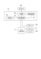
- FIG. 3 is a block diagram showing the configuration of a control system of the controller.
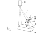
- FIG. 4 is an explanatory diagram for explaining the range in which the relative positions of the suction units can be changed.
- FIG. 5 is an explanatory diagram showing the camera position and the hand center position on the XY plane of the work coordinate system.
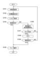
- FIG. 6 is a flow chart of the pick and place process.
- Figure 1 is a schematic diagram showing the configuration of a robot system 100.
- the robot system 100 includes a robot 1 and a main control device 3 that controls the robot 1.
- the main control device 3 controls the robot 1 to cause the robot 1 to execute a process.
- the process performed by the robot 1 is a pick-and-place process.
- the robot 1 picks up a target workpiece from a first container 91 in which multiple workpieces are piled up randomly, and transfers it into a second container 92.
- the robot 1 arranges the target workpieces in a regular pattern in the second container 92.
- the robot system 100 arranges the multiple workpieces in the first container 91 into the second container 92 by repeating the pick-and-place process.
- the robot system 100 may include a camera 51 that captures an image of the workpiece.
- the camera 51 is fixedly disposed above the first container 91.
- the camera 51 captures an image of the inside of the first container 91 from above.
- the camera 51 captures an image including a plurality of workpieces in the first container 91.
- the image is a two-dimensional image or a three-dimensional image.
- the three-dimensional image may be point cloud data, an RGB-D image, an RGB image, a depth image, a voxel, or the like.
- the camera 51 may be a three-dimensional camera, i.e., an RGB-D camera that outputs an RGB-D image, a stereo camera that captures an RGB image, or a three-dimensional vision sensor that captures point cloud data.
- the camera 51 may also capture an image of the first container 91.
- the camera 51 may also capture an image of the inside of the second container 92.
- the robot 1 has a robot arm 12 and a hand 14 attached to the robot arm 12.
- the robot 1 is an industrial robot.
- the hand 14 is a so-called end effector.
- a base coordinate system with three orthogonal axes is defined in the space in which the robot 1 is placed.
- the W axis is set in the vertical direction
- the U axis and V axis are set in the horizontal direction, perpendicular to each other.
- the robot arm 12 is configured to operate in a three-dimensional manner. Specifically, the robot arm 12 is configured to perform operations including translation with at least three degrees of freedom.
- the robot arm 12 is a vertical multi-joint robot arm.
- the robot arm 12 is supported by the base 10.
- the robot arm 12 has multiple links, multiple joints that connect the multiple links, and a servo motor that rotates the multiple joints.
- the robot arm 12 has a first link 12a connected to the base 10, a second link 12b connected to the first link 12a, a third link 12c connected to the second link 12b, a fourth link 12d connected to the third link 12c, and a fifth link 12e connected to the fourth link 12d.
- the base 10 and the first link 12a are connected to each other via a first joint 13a that can rotate around an axis extending in the vertical direction.
- the first link 12a and the second link 12b are connected to each other via a second joint 13b that can rotate around an axis extending in the horizontal direction.
- the second link 12b and the third link 12c are connected to each other via a third joint 13c that can rotate around an axis extending in the horizontal direction.
- the third link 12c and the fourth link 12d are connected to each other via a fourth joint 13d that can rotate around the axis of the fourth link 12d (i.e., the direction in which the fourth link 12d extends).
- the fourth link 12d and the fifth link 12e are connected to each other via a fifth joint 13e that can rotate around an axis perpendicular to the axis of the fourth link 12d.
- the robot arm 12 has servo motors 16 (see Figure 2) that rotate each joint.
- Each servo motor 16 has an encoder 16a (see Figure 2).
- the robot arm 12 configured in this manner is configured to perform translational movements in the X-axis, Y-axis, and Z-axis directions, as well as rotational movements around the X-axis, Y-axis, and Z-axis.
- the hand 14 has a suction device 15, which sucks up the workpiece.
- the suction device 15 has a suction pad.
- An air hose that is connected to a negative pressure generator is connected to the suction device 15.
- the air hose is provided with a solenoid valve that serves as an actuator 15a (see FIG. 2). By controlling the solenoid valve, the suction device 15 can switch between suction and release.
- the suction device 15 sucks up the surface of the target workpiece W.
- the air hose is provided with a pressure sensor 15b.
- the pressure sensor 15b detects the magnitude of the negative pressure in the air hose.
- the suction device 15 is configured to be able to change its position relative to the robot arm 12.
- the hand 14 is attached to the robot arm 12 so as to be rotatable around a predetermined rotation axis T.
- the hand 14 is connected to the tip of the robot arm 12, i.e., the fifth link 12e.
- the fifth link 12e and the hand 14 are connected to each other via the sixth joint 13f so as to be rotatable around the rotation axis T.
- the suction device 15 is disposed in an eccentric position with respect to the rotation axis T.
- the suction device 15 changes its relative position with respect to the robot arm 12 by the rotation of the hand 14 around the rotation axis T.
- the position of the suction device 15 with respect to the robot arm 12 will also be simply referred to as the "relative position of the suction device.”
- FIG. 2 is a diagram showing the general hardware configuration of the robot controller 2 and the main controller 3.
- the main controller 3 transmits and receives signals and information to and from the robot controller 2.
- the main controller 3 controls the robot 1 via the robot controller 2.
- the main controller 3 outputs commands to the robot controller 2.
- the robot controller 2 controls the servo motor 16 of the robot arm 12 in response to commands from the main controller 3.
- An image from the camera 51 is input to the main control device 3.
- the main control device 3 detects the target workpiece W based on the image.
- the main control device 3 generates a target path for the robot 1 based on the detected target workpiece W, and outputs a command corresponding to the generated target path to the robot control device 2.
- An actuator 15a and a pressure sensor 15b are connected to the main control device 3.
- the main control device 3 controls suction by the hand 14 via the actuator 15a and the pressure sensor 15b.
- the main control device 3 is an example of a control device.
- the robot control device 2 has a controller 21, a storage device 22, and a memory 23.
- the controller 21 controls the entire robot control device 2.
- the controller 21 performs various types of arithmetic processing.
- the controller 21 is formed of a processor such as a CPU (Central Processing Unit).
- the controller 21 may also be formed of an MCU (Micro Controller Unit), an MPU (Micro Processor Unit), an FPGA (Field Programmable Gate Array), a PLC (Programmable Logic Controller), a system LSI, etc.
- the memory 22 stores the programs executed by the controller 21 and various data.
- the memory 22 is formed of a non-volatile memory, a hard disc drive (HDD), a solid state drive (SSD), etc.
- the memory 23 temporarily stores data, etc.
- the memory 23 is formed of a volatile memory.
- the controller 21 drives the servo motor 16 based on a command from the main control device 3. At this time, the robot control device 2 feedback controls the current supplied to the servo motor 16 based on the detection result of the encoder 16a.
- the main control device 3 has a controller 31, a memory 32, and a memory 33.
- the controller 31 controls the entire main control device 3.
- the controller 31 performs various types of arithmetic processing.
- the controller 31 is formed of a processor such as a CPU (Central Processing Unit).
- the controller 31 may also be formed of an MCU (Micro Controller Unit), an MPU (Micro Processor Unit), an FPGA (Field Programmable Gate Array), a PLC (Programmable Logic Controller), a system LSI, etc.
- the memory 32 stores the programs and various data executed by the controller 31.
- the memory 32 is formed of a non-volatile memory, a HDD (Hard Disc Drive), an SSD (Solid State Drive), etc.
- the memory 32 stores an object detection program 41 for detecting objects and an object detection model 42.
- the object detection program 41 causes the main control device 3 to realize various functions and detect objects.
- the object detection model 42 is a trained model through machine learning.
- the memory 32 stores a path generation program 43 for generating a target path for the robot 1.
- the path generation program 43 causes the main control device 3 to realize various functions and generate a target path.
- Memory 33 temporarily stores data, etc.
- memory 33 is formed of a volatile memory.
- Memory 33 stores images from camera 51.
- the controller 31 causes the robot 1 to execute a picking operation in which the suction device 15 moves to the target workpiece W and causes the suction device 15 to suction the target workpiece W, and a placing operation in which the suction device 15, which has suctioned the target workpiece W, moves to a target placement position and causes the suction device 15 to release suction from the target workpiece W.
- the controller 31 causes the robot 1 to execute a placing operation after the picking operation.
- the robot arm 12 and the hand 14 move from a starting position to a picking target position along a target path.
- the picking target position is the respective positions of the robot arm 12 and the hand 14 when the suction device 15 comes into contact with the target surface S of the target workpiece W.
- the suction device 15 sucks the target surface S of the target workpiece W.
- the suction device 15 picks up an uneven portion of the workpiece, or if the suction device 15 picks up the boundary between multiple workpieces, the suction may fail. If the suction fails, the controller 31 causes the robot 1 to re-execute the picking operation. When re-executing the picking operation, the controller 31 changes the suction position on the target surface S.
- the controller 31 Prior to the picking operation, the controller 31 detects the target surface S of the target workpiece W from the image, and generates a target path for the robot 1 in the picking operation based on the target surface S. Furthermore, the controller 31 generates a target path for the robot 1 in the placing operation based on the target surface S.
- the controller 31 controls the camera 51 to capture an image of the workpiece.
- the controller 31 stores the image from the camera 51 in the memory 33.
- FIG. 3 is a block diagram showing the configuration of the control system of the controller 31.
- the controller 31 realizes various functions by reading out a program from the storage device 32 into the memory 33 and expanding it.
- the controller 31 functions as a detector 34 that detects the target surface S of the target workpiece W from an image including the target workpiece W, an operation controller 35 that causes the robot 1 to perform a picking operation, and a determiner 36 that determines whether the suction device 15 has successfully adsorbed the target workpiece W.
- the controller 31 also functions as a range calculator 37 that calculates the range of change in the relative position of the suction device 15 if suction has failed.
- the operation controller 35 also causes the robot 1 to perform a placing operation.
- Detector 34 detects the surface of the workpiece from the image captured by camera 51 by image recognition. Detector 34 may control camera 51 to cause camera 51 to capture an image. The image may include multiple workpieces. Detector 34 performs plane detection, for example, by RANSAC (Random Sample Consensus), to detect a target surface S that may be a target for picking. Detector 34 may detect multiple target surfaces S.
- RANSAC Random Sample Consensus
- the operation controller 35 selects one target surface S from the detected target surfaces S. For example, the operation controller 35 selects the target surface S based on the ease of access by the suction device 15 or the shortness of the cycle time.
- the motion controller 35 generates a target path for the robot arm 12 and hand 14 based on the target surface S.
- the motion controller 35 generates a target path for the robot arm 12 and hand 14 in a picking operation when adsorbing the target surface S. Furthermore, the motion controller 35 generates a target path for the robot arm 12 and hand 14 in a placing operation after adsorbing the target surface S.
- the target path is an ordered set of target positions and target postures of the robot arm 12 and hand 14. That is, the target path is the change over time of the target position and target posture of the robot arm 12 and hand 14.
- the target path may also be an ordered set of target rotation angles of each joint of the robot arm 12 (including the sixth joint 13f) that realizes the change over time of the target position and target posture of the robot arm 12 and hand 14.
- the target path uniquely defines the position and posture of the robot arm 12 and hand 14. Therefore, the target path also defines the relative position of the suction device 15, i.e., the target rotation position of the suction device 15 around the rotation axis T.
- the motion controller 35 executes path planning using the Probabilistic Roadmap Method (PRM) or the Rapidly-Exploring Random Tree (RRT), etc. In these methods, the motion controller 35 also executes an interference check, i.e., checks whether the robot arm 12 and the hand 14 interfere with other objects.
- the interference check may be, for example, an interference check using point cloud data or CAD data.
- the motion controller 35 outputs commands according to the target path to the robot control device 2. Specifically, the motion controller 35 outputs commands according to the target rotation angles of each joint of the robot arm 12 to the robot control device 2. As described above, the robot control device 2 drives the servo motor 16 based on the commands, causing the robot arm 12 and hand 14 to move along the target path.
- the operation controller 35 switches between suction by the suction device 15 and release of the suction by controlling the actuator 15a of the hand 14.
- the operation controller 35 controls the actuator 15a to generate negative pressure in the suction device 15, thereby causing the suction device 15 to suction the workpiece.
- the operation controller 35 controls the actuator 15a to release the negative pressure in the suction device 15, thereby causing the suction device 15 to release the suction of the workpiece.
- the determiner 36 determines whether the suction device 15 has successfully suctioned the target workpiece W based on the detection result of the pressure sensor 15b. The determiner 36 determines that suction has been successful when the negative pressure detected by the pressure sensor 15b is equal to or greater than a predetermined threshold, and determines that suction has failed when the negative pressure is less than the threshold.
- the operation controller 35 changes the relative position of the suction device 15 and causes the robot 1 to retry the picking operation, i.e., to retry, without changing the path of the robot arm 12. In other words, if suction fails, the operation controller 35 changes the relative position of the suction device 15 and causes the robot 1 to retry the picking operation.
- the path of the robot arm 12 is the same in the picking operation when it fails and in the picking operation when it is retried.
- the operation controller 35 when re-executing the picking operation, the operation controller 35 returns the robot arm 12 in the opposite direction along the target path from the state at the time of the pickup failure to a predetermined return position on the target path, changes the relative position of the suction device 15, and moves the robot arm 12 in the forward direction along the target path, thereby moving the suction device 15 again to the target workpiece W.
- the return position is the position of each of the robot arm 12 and hand 14 on the target path where the suction device 15 is a specified distance away from the target workpiece W.
- the motion controller 35 moves the robot arm 12 and hand 14 back along the target path from the state at the time of failure to the return position.
- the motion controller 35 moves the robot arm 12 and hand 14 back along the target path from the picking target position to the return position. Since the target path has been checked for interference, the robot arm 12 and hand 14 can move back along the target path without interfering with other objects.
- the section between the return position and the picking target position on the target path is a section in which the hand 14 moves approximately parallel to the direction of the rotation axis T.
- the return position is the position of the robot arm 12 and the hand 14 on the target path where the suction device 15 is separated a predetermined amount from the target workpiece W in the direction of the rotation axis T.
- the operation controller 35 changes the relative position of the suction device 15 within the space Q defined by a straight line connecting the camera 51 that captured the image and the contour of the target surface S of the target workpiece W.
- FIG. 4 is an explanatory diagram illustrating the range in which the relative position of the suction device 15 can be changed. In other words, when an image of the target surface S is captured by the camera 51, it is confirmed that no other objects exist within the space Q defined by a straight line connecting the camera 51 and the contour of the target surface S.
- the range calculator 37 calculates the change range of the relative position of the suction device 15.
- the operation controller 35 changes the relative position of the suction device 15 within the calculated change range.
- the range calculator 37 determines the position F (Xf, Yf, Zf) of the camera 51 and the position R (Xr, Yr, Zr) of the center of rotation of the hand 14 at the return position in the work coordinate system.
- the position of the camera 51 is simply referred to as the "camera position”
- the position of the center of rotation of the hand 14 at the return position is simply referred to as the "hand center position”.
- the work coordinate system is a coordinate system of three orthogonal axes set based on the target surface S of the target work W.
- the origin of the work coordinate system is located on the target surface S, and the Z axis of the work coordinate system extends in the normal direction of the target surface S.
- the X axis and Y axis of the work coordinate system are each perpendicular to the Z axis.
- a base coordinate system is set based on the robot 1.
- the base coordinate system has a U-axis, a V-axis, and a W-axis that are orthogonal to each other.
- the camera position and the hand center position in the base coordinate system of the robot 1 are known.
- the range calculator 37 uses a simultaneous coordinate transformation matrix or the like to convert the camera position and the hand center position in the base coordinate system into the camera position F and the hand center position R in the work coordinate system.
- FIG. 5 is an explanatory diagram showing the camera position F and the hand center position R on the XY plane of the work coordinate system.
- the origin of the work coordinate system is set to the suction position at the time of failure on the target surface S (i.e., the contact point between the target surface S and the suction device 15). Since the return position is a position where the hand 14 is away from the target surface S in the direction of the rotation axis T, the XY coordinates of the position of the suction device 15 when the hand 14 is located at the return position match the XY coordinates of the origin. In other words, in the XY plane, the suction device 15 of the hand 14 located at the intermediate position at the time of failure can be considered to be located at the origin. Since the Z axis and the rotation axis T of the work coordinate system are parallel, when the hand 14 rotates the suction device 15 at the return position, the suction device 15 rotates from the origin in the XY plane.
- the suction device 15 When the suction device 15 rotates around the rotation axis T, the suction device 15 approaches the camera 51 closest when it is located on the line connecting the camera position F and the hand center position R. As shown in FIG. 4, the camera 51 can capture the target surface S, so there are no other objects that would impede the capture of the target surface S in the space Q defined by the line connecting the camera 51 and the contour of the target surface S. The suction device 15 can be displaced in the space Q without interfering with other objects. The position at which the suction device 15 approaches the camera 51 is relatively inside the space Q. Therefore, as long as the suction device 15 approaches the camera 51 closest, the suction device 15 moves in the space Q.
- the position of the suction device 15 at the time of failure from the hand center position R on the XY plane that is, the angle ⁇ 1 between the vector vb toward the origin 0 and the vector va from the hand center position R toward the camera position F, is the rotation angle until the suction device 15 of the hand 14 located in the return position approaches the camera 51 closest.
- the suction device 15 When the suction device 15 rotates, it may move to a position where it does not overlap with the target surface S.
- the passing point where it passes over the contour of the target surface S is defined as P(Xp, Yp).
- the angle ⁇ 2 between the vector vb pointing from the hand center position R to the position of the suction device 15 at the time of failure and the vector vc pointing from the hand center position R to the passing point P is the rotation angle until the suction device 15 of the hand 14 at the time of failure moves onto the contour of the target surface S. If the suction device 15 rotates beyond ⁇ 2, the suction device 15 will move outside the target surface S.
- the operation controller 35 determines whether to retry the picking operation based on the change range ⁇ max of the relative position of the suction device 15. For example, the operation controller 35 determines not to retry the picking operation when the change range ⁇ max is less than a predetermined first threshold, and determines to retry the picking operation when the change range ⁇ max is equal to or greater than the first threshold. If the change range ⁇ max is too small, the suction position does not change much, and there is a high possibility that suction will fail even if a retry is performed.
- the operation controller 35 determines not to retry the picking operation when the change range ⁇ max is an angle ⁇ 2 and the angle ⁇ 2 is less than a predetermined second threshold, and determines to retry the picking operation when the change range ⁇ max is an angle ⁇ 2 and the angle ⁇ 2 is equal to or greater than the second threshold. If the angle ⁇ 2 is small, the suction position is at the edge of the target surface S or in its vicinity, so that the suction pad is more likely to protrude from the target surface S.
- the first threshold or the second threshold can be set based on the size of the suction pad of the suction unit 15. For example, the first threshold or the second threshold is larger than the size of the suction pad (i.e., the diameter of the suction pad if the contact portion of the suction pad is circular).
- the operation controller 35 determines the amount of change in the relative position of the suction device 15, i.e., the amount of rotation, within the change range ⁇ max. For example, the operation controller 35 determines the amount of rotation of the suction device 15 within the change range ⁇ max so that the position of the suction device 15 is changed to a size equal to or larger than the size of the suction pad. With the hand 14 positioned at the intermediate position, the operation controller 35 rotates the hand 14 around the rotation axis T by the determined amount of rotation to change the relative position of the suction device 15.
- the motion controller 35 moves the robot arm 12 in the forward direction along the target path, thereby moving the suction device 15, whose relative position has been changed, again to the target workpiece W. That is, the motion controller 35 moves the robot arm 12 along the target path from the return position to the picking target position. Since the target path of the robot arm 12 is the same for a failed picking operation and a re-executed picking operation, the robot arm 12 does not interfere with other objects. On the other hand, the relative position of the suction device 15, i.e., the posture of the hand 14, is different between a failed picking operation and a re-executed picking operation. However, since the relative position of the suction device 15 has been changed within the space Q as described above, the suction device 15 is also unlikely to interfere with other objects.
- the operation controller 35 causes the suction device 15 to suction the target workpiece W. Since the suction device 15 suctions a position on the target surface S that is different from the suction position at the time of failure, there is a possibility that suction will be successful. The success or failure of suction is determined by the determiner 36.
- FIG. 6 is a flowchart of the pick-and-place process.
- step S101 a target surface S of a target workpiece W to be picked is selected.
- the detector 34 causes the camera 51 to acquire an image, and detects the target surface S of the workpiece from the image captured by the camera 51. If multiple target surfaces S are detected, the operation controller 35 selects one target surface S from the multiple target surfaces S.
- step S102 the motion controller 35 generates target paths for the robot arm 12 and hand 14 in the picking and placing operations.
- the motion controller 35 also performs an interference check for the target paths.
- step S103 the motion controller 35 causes the robot 1 to execute a picking operation.
- the motion controller 35 moves the robot arm 12 and hand 14 along the target path, and moves the suction device 15 to the target surface S.
- the motion controller 35 causes the suction device 15 to adsorb the target surface S.
- Step S103 corresponds to causing the robot 1 to execute a picking operation in which the suction device 15 moves to the workpiece and adsorbs the workpiece to the suction device 15.
- step S104 the determiner 36 determines whether or not the suction has been successful based on the detection result of the pressure sensor 15b.
- Step S104 corresponds to determining whether or not the suction device 15 has been successful in suctioning the workpiece.
- the motion controller 35 causes the robot 1 to execute a placing operation in step S105.
- the motion controller 35 moves the robot arm 12 and hand 14 along the target path, and moves the hand 14 with the target workpiece W suctioned to the target placement position.
- the motion controller 35 causes the suction device 15 to release the suction of the target workpiece W. This completes the pick-and-place process.
- the process from step S101 is repeated for the pick-and-place process for another target workpiece W.
- the operation controller 35 calculates the change range ⁇ max of the relative position of the suction device 15 in step S106.
- step S107 the operation controller 35 determines whether or not to perform a retry based on the calculated change range ⁇ max. For example, the operation controller 35 determines whether or not to perform a retry based on the first threshold value and the second threshold value.
- the operation controller 35 stops the retry for the current target workpiece W.
- the controller 31 starts over from the selection of the target surface S in step S101.
- the controller 31 selects the target surface S of another target workpiece W from among multiple works.
- the controller 31 may use an existing image or may reacquire an image.
- the operation controller 35 causes the robot 1 to retry the picking operation in step S108.
- the operation controller 35 causes the robot arm 12 and hand 14 to move backwards along the target path, changes the relative position of the suction device 15, moves the robot arm 12 back along the target path, and causes the suction device 15 to pick up the target workpiece W.
- Step S108 corresponds to causing the robot 1 to retry the picking operation by changing the position of the suction device 15 relative to the robot arm 12 and without changing the path of the robot arm 12 if suction has failed.
- step S109 the determiner 36 determines whether or not the adsorption was successful based on the detection result of the pressure sensor 15b.
- the motion controller 35 causes the robot 1 to execute a placing operation in step S105.
- the placing operation is as described above.
- the operation controller 35 stops picking the current target workpiece W.
- the controller 31 starts over from the selection of the target surface S in step S101.
- the controller 31 selects the target surface S of another target workpiece W from among multiple works.
- the controller 31 may use an existing image or may reacquire an image.
- the controller 31 causes the robot 1 to execute the picking operation and the placing operation. If suction fails in the picking operation, the controller 31 causes the robot 1 to change the suction position and retry the picking operation. In retrying the picking operation, the robot arm 12 is caused to move back along the target path from the picking target position by a predetermined amount, the relative position of the suction device 15 is changed, and the robot arm 12 is moved again to the picking target position along the target path. Since the robot arm 12 only moves back and forth along the target path that has already been checked for interference, it will not interfere with other objects. Since the relative position of the suction device 15 is changed within the space Q where no other objects exist, the hand 14 is unlikely to interfere with other objects when retrying the picking operation.
- the target path of the robot arm 12 is the same as the target path at the time of failure, and the relative position of the suction device 15 is changed. In other words, it is necessary to recalculate the target path of the hand 14, i.e., the rotational position of the hand 14 around the rotation axis T, but it is not necessary to recalculate the target path of the robot arm 12. If the target work W is changed, it is necessary to recalculate the target paths of the robot arm 12 and the hand 14. In that case, an interference check using point cloud data or CAD data is also required.
- the target path of the robot arm 12 is also changed to change the suction position for the same target work W, it is necessary to recalculate the new target path and check for interference.
- the time required for path planning in a retry of a picking operation is shortened.
- the path planning of the hand 14 is performed based on the position information of the camera 51, the amount of calculation is smaller and the calculation time is shortened compared to when point cloud data or CAD data is used.
- the picking operation is not restarted from the beginning, but only the section of the target path between the return position and the picking target position is restarted by changing the relative position of the suction device 15. This also shortens the operation time during a retry.
- the robot system 100 incorporating the main control device 3 is not limited to one that transfers the target workpiece W from the first container 91 to the second container 92.
- the robot 1 may perform debunking.
- the robot 1 may perform assembly work such as incorporating the target workpiece W into another workpiece.
- the target work to be picked may not be randomly stacked, but may be aligned.
- the target work is not limited to a rectangular parallelepiped work.
- the target work may have an approximately triangular prism shape.
- the robot arm 12 is not limited to a vertical multi-joint type robot arm.
- the robot arm 12 may be a horizontal multi-joint type, a parallel link type, a Cartesian coordinate type, or a polar coordinate type robot arm, etc.
- the suction device 15 is not limited to a device that changes its position relative to the robot arm 12 by rotating around the rotation axis T.
- the suction device 15 may be supported by a guide so as to be movable along a straight line or a curve.
- the suction device 15 may move along a guide to change its position relative to the robot arm 12.
- the suction device 15 may also attract the workpiece by magnetic force or the like instead of negative pressure.
- the camera 51 may not be fixedly positioned, but may be attached to the robot arm 12 and moved by the robot arm 12.
- the robot system 100 may not be equipped with a camera 51. In that case, an image may be input to the main control device 3 from outside. The method of acquiring the image is not important. The image input from outside may be stored in the memory 33 or in the storage device 32.
- the main control device 3 does not have to have the detector 34 and the range calculator 37. Information on the target surface S may be input to the main control device 3 from outside.
- the main control device 3 may receive position information of the space Q, i.e., the position information of the camera 51 and the position information of the contour of the target surface S, from outside.
- the processing of the detector 34, the operation controller 35, the determiner 36, and the range calculator 37 is merely an example.
- the detector 34 may detect the target surface S from the image by various methods.
- the operation controller 35 may adopt any path plan.
- the amount of change in the relative position of the suction device 15 during a retry may be calculated by the operation controller 35.
- the operation controller 35 may calculate the path of the hand 14 during a retry, i.e., the amount of change in the relative position of the suction device 15, by a method similar to the target path of the first picking operation.
- the operation controller 35 may search for the relative position of the suction device 15 and perform an interference check in the section where the picking operation is redone.
- the range calculator 37 may not only calculate the change range of the relative position of the suction device 15, but also determine whether or not a retry is possible and determine the amount of change in the relative position of the suction device 15.
- the success or failure of suction by the determiner 36 does not have to be determined based on the negative pressure acting on the suction device 15.
- the success or failure of suction by the determiner 36 may be determined based on the load acting on the robot arm 12 when the suction device 15 is lifted.
- the control device does not have to be a single device such as the main control device 3.
- the control device may include multiple separate devices.
- the operation controller 35 and the determiner 36 may each be realized by separate devices.
- the flowchart is merely an example. Steps in the flowchart may be changed, replaced, added, omitted, etc. as appropriate. The order of steps in the flowchart may also be changed, and serial processing may be performed in parallel. For example, in a retry of a picking operation, a calculation of the change range of the suction device 15 in step S106 may be performed while the robot arm 12 is being returned to the return position.
- a processor includes transistors and other circuits and is considered a circuit or processing circuit.
- a processor may be a programmable processor that executes a program stored in a memory.
- a circuit, unit, or means is hardware that is programmed to realize or executes the described functions.
- the hardware may be any hardware disclosed in this specification or any hardware known to be programmed to realize or execute the described functions.
- the hardware is a processor that is considered to be a type of circuitry
- the circuit, means, or unit is a combination of the hardware and software used to configure the hardware and/or the processor.
- a main control device 3 that controls a robot 1 having a robot arm 12 and a hand 14 attached to the robot arm 12, including a suction device 15 whose position relative to the robot arm 12 can be changed, is equipped with an operation controller 35 that causes the robot 1 to execute a picking operation in which the suction device 15 moves to a workpiece and suctions the workpiece to the suction device 15, and a determiner 36 that determines whether the suction device 15 has succeeded in suctioning the workpiece. If the determination by the determiner 36 is failure, the operation controller 35 changes the position of the suction device 15 relative to the robot arm 12 and causes the robot 1 to re-execute the picking operation without changing the path of the robot arm 12.
- the operation controller 35 when re-executing the picking operation, causes the robot arm 12 to return in the opposite direction to a predetermined return position on the path, changes the position of the suction device 15 relative to the robot arm 12, and moves the robot arm 12 in the forward direction along the path, thereby moving the suction device 15 again to the workpiece.
- the main control device 3 described in [1] or [2] further includes a detector 34 that detects the target surface S of the workpiece to be picked up from an image including the workpiece, and the operation controller 35 changes the position of the suction device 15 relative to the robot arm 12 within a space Q defined by a straight line connecting the camera 51 that captured the image and the contour of the target surface S when re-executing the picking operation.
- the suction device 15 can be moved to a position where it does not interfere with other objects during the picking operation.
- the new position of the suction device 15 can be calculated based on the position information of the camera 51, so the calculation time can be reduced. This further reduces the overall time required to re-execute the picking operation.
- the robot system 100 includes a robot 1 having a robot arm 12 and a hand 14 attached to the robot arm 12, and a main control device 3 that controls the robot 1.
- the hand 14 includes a suction device 15 whose position relative to the robot arm 12 can be changed.
- the main control device 3 has an operation controller 35 that causes the robot 1 to execute a picking operation in which the suction device 15 moves to a workpiece and the suction device 15 picks up the workpiece, and a judger 36 that judges whether the suction device 15 has succeeded in picking up the workpiece. If the judger 36 judges that the picking operation has failed, the operation controller 35 changes the position of the suction device 15 relative to the robot arm 12 and causes the robot 1 to re-execute the picking operation without changing the path of the robot arm 12.
- the hand 14 is attached to the robot arm 12 so as to be rotatable around a predetermined rotation axis T, the suction device 15 is disposed in an eccentric position with respect to the rotation axis T, and the relative position with respect to the robot arm 12 is changed by rotating the hand 14 around the rotation axis T.
- the relative position of the suction device 15 can be easily changed by rotating the hand 14 around the rotation axis T.
- the method of controlling the robot includes having a robot 1 having a robot arm 12 and a hand 14 attached to the robot arm 12, the hand 14 including a suction device 15 whose position relative to the robot arm 12 can be changed, move the suction device 15 to a workpiece, and cause the suction device 15 to pick up the workpiece; determining whether the suction device 15 has successfully picked up the workpiece; and, if the suction has failed, changing the position of the suction device 15 relative to the robot arm 12 and causing the robot 1 to re-execute the picking operation without changing the path of the robot arm 12.
- Robot system 100 Robot system 1 Robot 12 Robot arm 14 Hand 15 Suction device 3 Main control device (control device) 34 Detector 35 Motion controller 36 Determiner 51 Camera S Target surface T Rotation axis Q Space
Landscapes
- Engineering & Computer Science (AREA)
- Human Computer Interaction (AREA)
- Robotics (AREA)
- Mechanical Engineering (AREA)
- Manipulator (AREA)
Abstract
主制御装置3は、ロボットアーム12、及び、ロボットアーム12に対する位置を変更可能な吸着器15を含みロボットアーム12に取り付けられたハンド14を有するロボット1を制御する。主制御装置3は、ロボット1に、吸着器15をワークまで移動させて吸着器15にワークを吸着させるピッキング動作を実行させる動作制御器35と、吸着器15によるワークの吸着の成否を判定する判定器36とを備える。動作制御器35は、判定器36による判定が失敗である場合に、ロボットアーム12に対する吸着器15の位置を変更し且つロボットアーム12の経路を変更することなく、ピッキング動作をロボット1に再実行させる。
Description
ここに開示された技術は、制御装置、ロボットシステム、ロボットの制御方法に関する。
従来より、ロボットアームに取り付けられたハンドによってワークをピッキングするロボットが知られている。例えば、特許文献1に開示されたロボットシステムは、マニピュレータ、即ち、ロボットアームを制御して、把持装置3、即ち、ハンドにワークを保持させる。ロボットシステムは、ハンドによるワークの保持が失敗した場合には、保持位置を変更して、ハンドによるワークのピッキングを再び実行させる。
ピッキングに失敗した場合にワークの保持位置の変更によってロボットアームの経路が変更されると、ロボットアームが他の物体に干渉する可能性がある。それを回避するためには、ロボットアームの経路計画において他の物体との干渉が発生しないか確認する必要があり、ピッキング動作に要する全体的な時間が長くなってしまう。
ここに開示された技術は、かかる点に鑑みてなされたものであり、その目的とするところは、ピッキング動作の再実行に要する時間を短縮することにある。
本開示の制御装置は、ロボットアーム、及び、前記ロボットアームに対する位置を変更可能な吸着器を含み前記ロボットアームに取り付けられたハンドを有するロボットを制御する制御装置であって、前記ロボットに、前記吸着器をワークまで移動させて前記吸着器にワークを吸着させるピッキング動作を実行させる動作制御器と、前記吸着器によるワークの吸着の成否を判定する判定器とを備え、前記動作制御器は、前記判定器による判定が失敗である場合に、前記ロボットアームに対する前記吸着器の位置を変更し且つ前記ロボットアームの経路を変更することなく、前記ピッキング動作を前記ロボットに再実行させる。
本開示のロボットシステムは、ロボットアーム及び前記ロボットアームに取り付けられたハンドを有するロボットと、前記ロボットを制御する制御装置とを備え、前記ハンドは、前記ロボットアームに対する位置を変更可能な吸着器を含み、前記制御装置は、前記ロボットに、前記吸着器をワークまで移動させて前記吸着器にワークを吸着させるピッキング動作を実行させる動作制御器と、前記吸着器によるワークの吸着の成否を判定する判定器とを有し、前記動作制御器は、前記判定器による判定が失敗である場合に、前記ロボットアームに対する前記吸着器の位置を変更し且つ前記ロボットアームの経路を変更することなく、前記ピッキング動作を前記ロボットに再実行させる。
本開示のロボットの制御方法は、ロボットアーム、及び、前記ロボットアームに対する位置を変更可能な吸着器を含み前記ロボットアームに取り付けられたハンドを有するロボットに、前記吸着器をワークまで移動させて前記吸着器にワークを吸着させるピッキング動作を実行させることと、前記吸着器によるワークの吸着の成否を判定することと、吸着が失敗である場合に、前記ロボットアームに対する前記吸着器の位置を変更し且つ前記ロボットアームの経路を変更することなく、前記ピッキング動作を前記ロボットに再実行させることとを含む。
前記制御装置によれば、ピッキング動作の再実行に要する時間を短縮することができる。
前記ロボットシステムによれば、ピッキング動作の再実行に要する時間を短縮することができる。
前記ロボットの制御方法によれば、ピッキング動作の再実行に要する時間を短縮することができる。
以下、例示的な実施形態を図面に基づいて詳細に説明する。図1は、ロボットシステム100の構成を示す模式図である。
ロボットシステム100は、ロボット1と、ロボット1を制御する主制御装置3とを備えている。主制御装置3は、ロボット1を制御してロボット1に処理を実行させる。この例では、ロボット1による処理は、ピックアンドプレース処理である。例えば、ロボット1は、複数のワークがバラ積みされた第1コンテナ91内の対象ワークをピッキングして第2コンテナ92内に移送する。ロボット1は、対象ワークを第2コンテナ92内に規則的に配列する。ロボットシステム100は、ピックアンドプレース処理を繰り返すことによって、第1コンテナ91内の複数のワークを第2コンテナ92内に配列する。
ロボットシステム100は、ワークの画像を取得するカメラ51を備えていてもよい。カメラ51は、第1コンテナ91の上方に固定的に配置されている。カメラ51は、第1コンテナ91内の画像を上方から撮影する。カメラ51は、第1コンテナ91内の複数のワークを含む画像を取得する。ここで、画像は、二次元画像又は三次元画像である。三次元画像は、点群データ、RGB-D画像、RGB画像、デプス画像又はボクセル等であり得る。つまり、カメラ51は、三次元カメラ、即ち、RGB-D画像を出力するRGB-Dカメラ、RGB画像を取得するステレオカメラ、又は、点群データを取得する三次元ビジョンセンサ等であり得る。尚、カメラ51は、第1コンテナ91の画像も取得し得る。カメラ51は、第2コンテナ92内の画像も取得し得る。
-ロボット-
ロボット1は、ロボットアーム12及びロボットアーム12に取り付けられたハンド14を有する。ロボット1は、この例では、産業用ロボットである。ハンド14は、いわゆるエンドエフェクタである。
ロボット1は、ロボットアーム12及びロボットアーム12に取り付けられたハンド14を有する。ロボット1は、この例では、産業用ロボットである。ハンド14は、いわゆるエンドエフェクタである。
ロボット1が配置される空間には、直交3軸のベース座標系が規定されている。例えば、上下方向にW軸が設定され、水平方向に互いに直交するU軸及びV軸が設定される。
ロボットアーム12は、三次元状に動作するように構成されている。具体的には、ロボットアーム12は、少なくとも3自由度の並進を含む動作を行うように構成されている。この例では、ロボットアーム12は、垂直多関節型のロボットアームである。ロボットアーム12は、ベース10に支持されている。ロボットアーム12は、複数のリンクと、複数のリンクを接続する複数の関節と、複数の関節を回転駆動するサーボモータとを有している。
詳しくは、ロボットアーム12は、ベース10に連結された第1リンク12aと、第1リンク12aに連結された第2リンク12bと、第2リンク12bに連結された第3リンク12cと、第3リンク12cに連結された第4リンク12dと、第4リンク12dに連結された第5リンク12eとを有している。
詳しくは、ベース10と第1リンク12aとは、鉛直方向に延びる軸回りに回転可能な第1関節13aを介して互いに連結されている。第1リンク12aと第2リンク12bとは、水平方向に延びる軸回りに回転可能な第2関節13bを介して互いに連結されている。第2リンク12bと第3リンク12cとは、水平方向に延びる軸回りに回転可能な第3関節13cを介して互いに連結されている。第3リンク12cと第4リンク12dとは、第4リンク12dの軸心(即ち、第4リンク12dが延びる方向)回りに回転可能な第4関節13dを介して互いに連結されている。第4リンク12dと第5リンク12eとは、第4リンク12dの軸心と直交する軸回りに回転可能な第5関節13eを介して互いに連結されている。
ロボットアーム12は、各関節を回転駆動するサーボモータ16(図2参照)を有している。各サーボモータ16は、エンコーダ16a(図2参照)を有している。
このように構成されたロボットアーム12は、X軸、Y軸及びZ軸方向への並進動作、並びにX軸、Y軸及びZ軸回りの回転動作を行うように構成されている。
ハンド14は、吸着器15を有し、吸着器15によってワークを吸着する。吸着器15は、吸着パッドを有している。吸着器15には、負圧発生装置に接続されたエアホースが接続されている。エアホースには、アクチュエータ15a(図2参照)としての電磁弁が設けられている。電磁弁が制御されることによって、吸着器15による吸着及びその解除が切り替えられる。吸着器15は、対象ワークWの面を吸着する。エアホースには、圧力センサ15bが設けられている。圧力センサ15bは、エアホース内の負圧の大きさを検出する。
吸着器15は、ロボットアーム12に対する位置を変更可能に構成されている。例えば、ハンド14は、所定の回転軸T回りに回転可能にロボットアーム12に取り付けられる。具体的には、ハンド14は、ロボットアーム12の先端部、即ち、第5リンク12eに連結されている。第5リンク12eとハンド14とは、回転軸T回りに回転可能に第6関節13fを介して互いに連結されている。吸着器15は、回転軸Tに対して偏心した位置に配置されている。吸着器15は、回転軸T回りのハンド14の回転によってロボットアーム12に対する相対位置を変更する。以下、ロボットアーム12に対する吸着器15の位置を単に「吸着器の相対位置」とも称する。
図2は、ロボット制御装置2及び主制御装置3の概略的なハードウェア構成を示す図である。主制御装置3は、ロボット制御装置2と信号及び情報等の送受信を行う。主制御装置3は、ロボット制御装置2を介してロボット1を制御する。主制御装置3は、指令をロボット制御装置2に出力する。ロボット制御装置2は、主制御装置3からの指令に応じて、ロボットアーム12のサーボモータ16を制御する。
主制御装置3には、カメラ51からの画像が入力される。主制御装置3は、画像に基づいて対象ワークWを検出する。それに加えて、主制御装置3は、検出された対象ワークWに基づいてロボット1の目標経路を生成し、生成された目標経路に対応する指令をロボット制御装置2に出力する。主制御装置3には、アクチュエータ15a及び圧力センサ15bが接続されている。主制御装置3は、アクチュエータ15a及び圧力センサ15bを介してハンド14による吸着を制御する。主制御装置3は、制御装置の一例である。
ロボット制御装置2は、制御器21と、記憶器22と、メモリ23とを有している。
制御器21は、ロボット制御装置2の全体を制御する。制御器21は、各種の演算処理を行う。例えば、制御器21は、CPU(Central Processing Unit)等のプロセッサで形成されている。制御器21は、MCU(Micro Controller Unit)、MPU(Micro Processor Unit)、FPGA(Field Programmable Gate Array)、PLC(Programmable Logic Controller)、システムLSI等で形成されていてもよい。
記憶器22は、制御器21で実行されるプログラム及び各種データを格納している。記憶器22は、不揮発性メモリ、HDD(Hard Disc Drive)又はSSD(Solid State Drive)等で形成される。メモリ23は、データ等を一時的に格納する。例えば、メモリ23は、揮発性メモリで形成される。
制御器21は、主制御装置3からの指令に基づいてサーボモータ16を駆動する。このとき、ロボット制御装置2は、エンコーダ16aの検出結果に基づいてサーボモータ16への供給電流をフィードバック制御する。
主制御装置3は、制御器31と、記憶器32と、メモリ33とを有している。
制御器31は、主制御装置3の全体を制御する。制御器31は、各種の演算処理を行う。例えば、制御器31は、CPU(Central Processing Unit)等のプロセッサで形成されている。制御器31は、MCU(Micro Controller Unit)、MPU(Micro Processor Unit)、FPGA(Field Programmable Gate Array)、PLC(Programmable Logic Controller)、システムLSI等で形成されていてもよい。
記憶器32は、制御器31で実行されるプログラム及び各種データを格納している。記憶器32は、不揮発性メモリ、HDD(Hard Disc Drive)又はSSD(Solid State Drive)等で形成される。
例えば、記憶器32は、物体を検出する物体検出プログラム41及び物体検出モデル42を格納している。物体検出プログラム41は、主制御装置3に各種機能を実現させ、物体を検出させる。物体検出モデル42は、機械学習による学習済みモデルである。記憶器32は、ロボット1の目標経路を生成する経路生成プログラム43を格納している。経路生成プログラム43は、主制御装置3に各種機能を実現させ、目標経路を生成させる。
メモリ33は、データ等を一時的に格納する。例えば、メモリ33は、揮発性メモリで形成される。メモリ33は、カメラ51からの画像を記憶する。
制御器31は、ロボット1に、吸着器15を対象ワークWまで移動させて吸着器15に対象ワークWを吸着させるピッキング動作及び対象ワークWを吸着した吸着器15をプレース目標位置まで移動させて吸着器15に対象ワークWの吸着を解除させるプレース動作を実行させる。制御器31は、ピッキング動作の後にプレース動作をロボット1に実行させる。
詳しくは、ピッキング動作では、ロボットアーム12及びハンド14は、開始位置からピッキング目標位置へ目標経路に従って移動する。ピッキング目標位置は、吸着器15が対象ワークWの対象面Sに接触するときのロボットアーム12及びハンド14のそれぞれの位置である。吸着器15は、対象ワークWの対象面Sを吸着する。
例えば、吸着器15がワークのうち凹凸がある部分を吸着したり、吸着器15が複数のワークの境目を吸着したりする場合には、吸着が失敗し得る。吸着に失敗した場合には、制御器31は、ロボット1にピッキング動作を再実行させる。ピッキング動作の再実行においては、制御器31は、対象面Sにおける吸着位置を変更する。
制御器31は、ピッキング動作に先立ち、画像から対象ワークWの対象面Sを検出し、ピッキング動作におけるロボット1の目標経路を対象面Sに基づいて生成する。さらに、制御器31は、プレース動作におけるロボット1の目標経路を対象面Sに基づいて生成する。
制御器31は、カメラ51を制御して、カメラ51にワークの画像を取得させる。制御器31は、カメラ51からの画像をメモリ33に記憶させる。
図3は、制御器31の制御系統の構成を示すブロック図である。制御器31は、記憶器32からプログラムをメモリ33に読み出して展開することによって、各種機能を実現する。詳しくは、制御器31は、対象ワークWを含む画像の中から、対象ワークWの対象面Sを検出する検出器34と、ロボット1にピッキング動作を実行させる動作制御器35と、吸着器15による対象ワークWの吸着の成否を判定する判定器36として機能する。制御器31は、吸着に失敗した場合に、吸着器15の相対位置の変更範囲を演算する範囲演算器37としても機能する。尚、動作制御器35は、ロボット1にプレース動作も実行させる。
検出器34は、カメラ51による画像の中からワークの面を画像認識によって検出する。検出器34は、カメラ51を制御して、カメラ51に画像を取得させてもよい。画像には、複数のワークが含まれ得る。検出器34は、例えば、RANSAC(Random Sample Consensus)によって平面検出を行って、ピッキングの対象となり得る対象面Sを検出する。検出器34は、複数の対象面Sを検出し得る。
動作制御器35は、検出された対象面Sの中から一の対象面Sを選定する。例えば、動作制御器35は、吸着器15によるアクセスのし易さ、又は、サイクルタイムの短さを基準に、対象面Sを選定する。
動作制御器35は、対象面Sに基づいて、ロボットアーム12及びハンド14の目標経路を生成する。動作制御器35は、対象面Sを吸着する場合のピッキング動作におけるロボットアーム12及びハンド14の目標経路を生成する。さらに、動作制御器35は、対象面Sを吸着した後のプレース動作におけるロボットアーム12及びハンド14の目標経路を生成する。
目標経路は、ロボットアーム12及びハンド14の目標位置及び目標姿勢の順序集合である。すなわち、目標経路は、ロボットアーム12及びハンド14の目標位置及び目標姿勢の経時的な変化である。目標経路は、ロボットアーム12及びハンド14の目標位置及び目標姿勢の経時的な変化を実現する、ロボットアーム12の各関節(第6関節13fを含む)の目標回転角度の順序集合であってもよい。目標経路は、ロボットアーム12及びハンド14の位置及び姿勢を一義的に規定する。そのため、目標経路は、吸着器15の相対位置、即ち、回転軸T回りの吸着器15の目標回転位置も規定する。
例えば、動作制御器35は、PRM(Probabilistic Roadmap Method)又はRRT(Rapidly-Exploring Random Tree)等によって経路計画を実行する。動作制御器35は、これらの手法において干渉チェック、即ち、ロボットアーム12及びハンド14が他の物体と干渉しないかの確認も実行する。干渉チェックとしては、例えば、点群データ又はCADデータを用いた干渉チェック等が行われる。
動作制御器35は、目標経路に応じた指令をロボット制御装置2に出力する。具体的には、動作制御器35は、ロボットアーム12の各関節の目標回転角度に応じた指令をロボット制御装置2に出力する。ロボット制御装置2が前述の如く、指令に基づいてサーボモータ16を駆動することによって、ロボットアーム12及びハンド14が目標経路に従って移動する。
動作制御器35は、ハンド14のアクチュエータ15aを制御することによって吸着器15による吸着及びその解除を切り替える。動作制御器35は、アクチュエータ15aを制御して吸着器15に負圧を発生させることによって、吸着器15にワークを吸着させる。動作制御器35は、アクチュエータ15aを制御して吸着器15の負圧を解放することによって、吸着器15によるワークの吸着を解除させる。
判定器36は、圧力センサ15bの検出結果に基づいて、吸着器15による対象ワークWの吸着の成否を判定する。判定器36は、圧力センサ15bによって検出される負圧が所定の閾値以上になる場合に吸着の成功を判定する一方、負圧が閾値未満の場合に吸着に失敗を判定する。
動作制御器35は、判定器36による判定が失敗である場合に、吸着器15の相対位置を変更し且つロボットアーム12の経路を変更することなく、ロボット1にピッキング動作を再実行、即ち、リトライさせる。つまり、動作制御器35は、吸着が失敗した場合に、吸着器15の相対位置を変更してロボット1にピッキング動作をリトライさせる。失敗時のピッキング動作とリトライ時のピッキング動作では、ロボットアーム12の経路は同じである。
詳しくは、動作制御器35は、ピッキング動作の再実行において、ロボットアーム12を吸着の失敗時の状態から目標経路上の所定の戻り位置まで目標経路を逆方向に戻らせ、吸着器15の相対位置を変更し、ロボットアーム12を目標経路に従って順方向へ移動させることによって吸着器15を対象ワークWまで再び移動させる。
戻り位置は、吸着器15が対象ワークWから所定量だけ離れた状態となる、目標経路上のロボットアーム12及びハンド14のそれぞれの位置である。動作制御器35は、ロボットアーム12及びハンド14を失敗時の状態から戻り位置まで目標経路を逆行させる。この例では、失敗時にはロボットアーム12及びハンド14はピッキング目標位置に位置するので、動作制御器35は、ロボットアーム12及びハンド14をピッキング目標位置から戻り位置まで目標経路を逆行させる。目標経路は干渉チェック済なので、ロボットアーム12及びハンド14は、他の物体と干渉することなく、目標経路を逆行することができる。
好ましくは、目標経路における戻り位置とピッキング目標位置との間の区間は、ハンド14が回転軸Tの方向へ概ね平行移動する区間である。戻り位置とピッキング目標位置との間では、ハンド14は、姿勢を変えることなく回転軸Tの方向へ移動する。つまり、戻り位置は、吸着器15が回転軸Tの方向において対象ワークWから所定量だけ離れた状態となる、目標経路上のロボットアーム12及びハンド14のそれぞれの位置である。
動作制御器35は、ピッキング動作の再実行において、画像を取得したカメラ51と対象ワークWの対象面Sの輪郭とを結ぶ直線で区画される空間Q内で、吸着器15の相対位置を変更する。図4は、吸着器15の相対位置の変更範囲を説明する説明図である。つまり、カメラ51によって対象面Sの画像が撮影されている場合、カメラ51と対象面Sの輪郭とを結ぶ直線で区画される空間Q内には、他の物体が存在しないことが確認されている。そのため、吸着器15の相対位置を空間Q内で変更することによって、吸着器15と他の物体との干渉を回避できると共に、対象面Sと変更後の吸着器15との間に他の物体が存在しない位置に吸着器15を移動させることができる。
吸着器15の相対位置の変更に関し、範囲演算器37は、吸着器15の相対位置の変更範囲を演算する。動作制御器35は、演算された変更範囲内で吸着器15の相対位置を変更する。例えば、範囲演算器37は、ワーク座標系における、カメラ51の位置F(Xf,Yf,Zf)と戻り位置におけるハンド14の回転中心の位置R(Xr,Yr,Zr)とを求める。以下、カメラ51の位置を単に「カメラ位置」といい、戻り位置におけるハンド14の回転中心の位置を単に「ハンド中心位置」という。ワーク座標系とは、対象ワークWの対象面Sを基準に設定された直交三軸の座標系である。ワーク座標系の原点は、対象面S上に位置し、ワーク座標系のZ軸は対象面Sの法線方向に延びる。ワーク座標系のX軸及びY軸はそれぞれ、Z軸に直交する。一方、ロボット1を基準としてベース座標系が設定されている。ベース座標系は、互いに直交するU軸、V軸及びW軸を有している。ロボット1のベース座標系における、カメラ位置とハンド中心位置とは既知である。例えば、範囲演算器37は、同時座標変換行列等を用いて、ベース座標系におけるカメラ位置及びハンド中心位置をワーク座標系におけるカメラ位置F及びハンド中心位置Rに変換する。
図5は、ワーク座標系のXY平面におけるカメラ位置F及びハンド中心位置Rを示す説明図である。対象面Sにおける失敗時の吸着位置(即ち、対象面Sと吸着器15との接触点)にワーク座標系の原点が設定される。戻り位置はハンド14が対象面Sから回転軸Tの方向に離れた位置であるので、戻り位置にハンド14が位置する場合の吸着器15の位置のXY座標は、原点のXY座標と一致する。つまり、XY平面内では、失敗時の経由位置に位置するハンド14の吸着器15は、原点に位置するとみなすことができる。ワーク座標系のZ軸と回転軸Tとは平行なので、ハンド14が戻り位置において吸着器15を回転させると、吸着器15は、原点からXY平面内で回転する。
吸着器15が回転軸T回りに回転する場合、カメラ位置Fとハンド中心位置Rとを結ぶ直線上に吸着器15が位置するときに、吸着器15は、カメラ51に最も接近する。図4に示されるように、カメラ51は対象面Sを撮影可能なので、カメラ51と対象面Sの輪郭とを結ぶ直線で区画される空間Q内には、対象面Sの撮影を阻害する他の物体が存在しない。吸着器15は、空間Q内において他の物体に干渉することなく変位できる。そして、吸着器15がカメラ51に最接近する位置は空間Q内の比較的内側に位置する。そのため、吸着器15がカメラ51へ最接近する限り、吸着器15は空間Q内で移動する。XY平面においてハンド中心位置Rから失敗時の吸着器15の位置、即ち、原点0へ向かうベクトルvbとハンド中心位置Rからカメラ位置Fへ向かうベクトルvaとのなす角θ1は、戻り位置に位置するハンド14の吸着器15がカメラ51に最接近するまでの回転角度である。
吸着器15が回転する場合に、吸着器15が対象面Sと重ならない位置まで移動する場合がある。戻り位置のハンド14の吸着器15がカメラ51に接近する方向へ回転する場合に対象面Sの輪郭上を通過する通過点をP(Xp,Yp)とする。XY平面においてハンド中心位置Rから失敗時の吸着器15の位置へ向かうベクトルvbとハンド中心位置Rから通過点Pへ向かうベクトルvcとのなす角θ2は、失敗時のハンド14の吸着器15が対象面Sの輪郭上に移動するまでの回転角度である。吸着器15がθ2を超えて回転すると、吸着器15が対象面Sの外まで移動してしまう。
範囲演算器37は、なす角θ1、θ2を演算して、なす角θ1、θ2のうち小さい方を吸着器15の回転可能範囲、即ち、吸着器15の相対位置の変更範囲θmaxとして設定する。尚、通過点Pが存在しない場合には、θ2は、2πとされる。つまり、θmax=θ1となる。
動作制御器35は、ピッキング動作のリトライを実行するか否かを吸着器15の相対位置の変更範囲θmaxに基づいて判定する。例えば、動作制御器35は、変更範囲θmaxが所定の第1閾値未満の場合にはピッキング動作のリトライを実行しないと判定する一方、変更範囲θmaxが第1閾値以上の場合にはピッキング動作のリトライを実行すると判定する。変更範囲θmaxが小さすぎる場合には、吸着位置があまり変化せず、リトライを実行しても吸着に失敗する可能性が高い。あるいは、動作制御器35は、変更範囲θmaxがなす角θ2であって且つなす角θ2が所定の第2閾値未満の場合にはピッキング動作のリトライを実行しないと判定する一方、変更範囲θmaxがなす角θ2であって且つなす角θ2が第2閾値以上の場合にはピッキング動作のリトライを実行すると判定する。なす角θ2が小さい場合には、吸着位置が対象面Sの縁又はその近傍になるので、吸着パッドが対象面Sからはみ出す可能性が高くなる。第1閾値又は第2閾値は、吸着器15の吸着パッドの大きさに基づいて設定され得る。例えば、第1閾値又は第2閾値は、吸着パッドの大きさ(即ち、吸着パッドの接触部分が円形の場合には吸着パッドの直径)よりも大きい。
動作制御器35は、リトライを実行する場合には、吸着器15の相対位置の変更量、即ち、回転量を変更範囲θmaxの中で決定する。例えば、動作制御器35は、変更範囲θmax内で、吸着器15の位置が吸着パッドの大きさ以上に変更されるように、吸着器15の回転量を決定する。動作制御器35は、ハンド14が経由位置に位置する状態で、ハンド14を回転軸T回りに、決定された回転量回転させて、吸着器15の相対位置を変更する。
動作制御器35は、ロボットアーム12を目標経路に従って順方向へ移動させることによって、相対位置の変更後の吸着器15を対象ワークWまで再び移動させる。つまり、動作制御器35は、ロボットアーム12を戻り位置からピッキング目標位置まで目標経路に従って移動させる。失敗時のピッキング動作と再実行のピッキング動作とでロボットアーム12の目標経路は同じなので、ロボットアーム12は他の物体に干渉しない。一方、吸着器15の相対位置、即ち、ハンド14の姿勢は、失敗時のピッキング動作と再実行のピッキング動作とで異なっている。しかし、吸着器15の相対位置は前述のように空間Q内で変更されているので、吸着器15も他の物体に干渉する可能性が低い。
続いて、動作制御器35は、吸着器15に対象ワークWを吸着させる。吸着器15は、対象面Sのうち失敗時の吸着位置と異なる位置を吸着するので、吸着が成功する可能性がある。吸着の成否は、判定器36によって判定される。
続いて、このように構成されたロボットシステム100の動作について説明する。ロボットシステム100におけるピックアンドプレース処理について図6のフローチャートを参照して説明する。図6は、ピックアンドプレース処理のフローチャートである。
まず、ステップS101において、ピッキングの対象となる対象ワークWの対象面Sが選定される。詳しくは、検出器34は、カメラ51に画像を取得させ、カメラ51による画像の中からワークの対象面Sを検出する。複数の対象面Sが検出された場合には、動作制御器35は、複数の対象面Sの中から一の対象面Sを選定する。
次に、ステップS102において、動作制御器35は、ピッキング動作及びプレース動作におけるロボットアーム12及びハンド14の目標経路を生成する。動作制御器35は、目標経路の干渉チェックも実行する。
そして、ステップS103において、動作制御器35は、ロボット1にピッキング動作を実行させる。動作制御器35は、ロボットアーム12及びハンド14を目標経路に従って移動させ、吸着器15を対象面Sまで移動させる。動作制御器35は、吸着器15に対象面Sを吸着させる。ステップS103は、ロボット1に、吸着器15をワークまで移動させて吸着器15にワークを吸着させるピッキング動作を実行させることに相当する。
その後、ステップS104において、判定器36は、圧力センサ15bの検出結果に基づいて吸着の成否を判定する。ステップS104は、吸着器15によるワークの吸着の成否を判定することに相当する。
吸着が成功した場合には、動作制御器35は、ステップS105において、ロボット1にプレース動作を実行させる。動作制御器35は、ロボットアーム12及びハンド14を目標経路に従って移動させ、対象ワークWを吸着した状態のハンド14をプレース目標位置まで移動させる。ロボットアーム12及びハンド14がプレース目標位置に到達すると、動作制御器35は、吸着器15による対象ワークWの吸着を解除させる。これにより、ピックアンドプレース処理が完了する。一の対象ワークWについてピックアンドプレース処理が完了すると、別の対象ワークWのピックアンドプレース処理のために、ステップS101からの処理が繰り返される。
一方、吸着が失敗した場合には、動作制御器35は、ステップS106において、吸着器15の相対位置の変更範囲θmaxを算出する。
続いて、動作制御器35は、ステップS107において、算出された変更範囲θmaxに基づいてリトライの可否を判定する。例えば、動作制御器35は、第1閾値及び第2閾値に基づいてリトライの可否を判定する。
リトライが不可能と判定された場合には、動作制御器35は、現在の対象ワークWに対するリトライを中止する。その場合、制御器31は、ステップS101の対象面Sの選定からやり直す。つまり、制御器31は、複数のワークの中から別の対象ワークWの対象面Sを選定する。この場合、制御器31は、既存の画像を用いてもよいし、画像を再取得してもよい。
リトライが可能と判定された場合には、動作制御器35は、ステップS108において、ロボット1にピッキング動作のリトライを実行させる。前述の如く、動作制御器35は、ロボットアーム12及びハンド14の目標経路の逆行、吸着器15の相対位置の変更、ロボットアーム12の目標経路の再移動、及び、吸着器15による対象ワークWの吸着を実行させる。ステップS108は、吸着が失敗である場合に、ロボットアーム12に対する吸着器15の位置を変更し且つロボットアーム12の経路を変更することなく、ピッキング動作をロボット1に再実行させることに相当する。
その後、判定器36は、ステップS109において、圧力センサ15bの検出結果に基づいて吸着の成否を判定する。
吸着が成功した場合には、動作制御器35は、ステップS105において、ロボット1にプレース動作を実行させる。プレース動作は、前述の説明の通りである。
吸着が失敗した場合には、動作制御器35は、現在の対象ワークWに対するピッキングを中止する。その場合、制御器31は、ステップS101の対象面Sの選定からやり直す。つまり、制御器31は、複数のワークの中から別の対象ワークWの対象面Sを選定する。この場合、制御器31は、既存の画像を用いてもよいし、画像を再取得してもよい。
このように、制御器31は、ロボット1にピッキング動作及びプレース動作を実行させる。ピッキング動作で吸着が失敗した場合には、制御器31は、ロボット1に吸着位置を変更させて、ピッキング動作のリトライを実行させる。ピッキング動作のリトライでは、ロボットアーム12をピッキング目標位置から所定量だけ目標経路を逆行させ、吸着器15の相対位置を変更させ、ロボットアーム12を目標経路に従ってピッキング目標位置まで再び移動させる。ロボットアーム12は、既に干渉チェック済みの目標経路を往復するだけなので、他の物体と干渉することはない。吸着器15の相対位置は、他の物体が存在しない空間Q内で変更されるので、ハンド14は、ピッキング動作のリトライにおいて他の物体と干渉する可能性は低い。
ピッキング動作のリトライにおいて、ロボットアーム12の目標経路は失敗時の目標経路と同じであり、吸着器15の相対位置が変更される。つまり、ハンド14の目標経路、即ち、回転軸T回りのハンド14の回転位置を再計算する必要があるが、ロボットアーム12の目標経路を再計算する必要がない。仮に、対象ワークWが変更されると、ロボットアーム12及びハンド14の目標経路を再計算する必要がある。その際、点群データ又はCADデータを用いた干渉チェックも必要になる。あるいは、同じ対象ワークWに対して吸着位置を変更するためにロボットアーム12の目標経路も変更すると、新たな目標経路の再計算及び干渉チェックが必要になる。つまり、ロボットアーム12の目標経路を変更せずに吸着器15の相対位置を変更することによって、ピッキング動作のリトライにおける経路計画に要する時間が短縮される。それに加えて、ハンド14の経路計画はカメラ51の位置情報に基づいて行われるため、点群データ又はCADデータを用いる場合と比較して演算量が少なく、演算時間も短縮される。
さらに、ピッキング動作のリトライは、ピッキング動作の最初からやり直されるわけではなく、吸着器15の相対位置を変更して目標経路のうち戻り位置とピッキング目標位置との間の区間だけがやり直される。そのため、リトライにおける動作時間も短縮される。
こうして目標経路の演算時間及びリトライの動作時間が短縮されるので、ピッキング動作のリトライに要する全体的な時間が短縮される。
《その他の実施形態》
以上のように、本出願において開示する技術の例示として、前記実施形態を説明した。しかしながら、本開示における技術は、これに限定されず、適宜、変更、置き換え、付加、省略などを行った実施の形態にも適用可能である。また、前記実施形態で説明した各構成要素を組み合わせて、新たな実施の形態とすることも可能である。また、添付図面および詳細な説明に記載された構成要素の中には、課題解決のために必須な構成要素だけでなく、前記技術を例示するために、課題解決のためには必須でない構成要素も含まれ得る。そのため、それらの必須ではない構成要素が添付図面や詳細な説明に記載されていることをもって、直ちに、それらの必須ではない構成要素が必須であるとの認定をするべきではない。
以上のように、本出願において開示する技術の例示として、前記実施形態を説明した。しかしながら、本開示における技術は、これに限定されず、適宜、変更、置き換え、付加、省略などを行った実施の形態にも適用可能である。また、前記実施形態で説明した各構成要素を組み合わせて、新たな実施の形態とすることも可能である。また、添付図面および詳細な説明に記載された構成要素の中には、課題解決のために必須な構成要素だけでなく、前記技術を例示するために、課題解決のためには必須でない構成要素も含まれ得る。そのため、それらの必須ではない構成要素が添付図面や詳細な説明に記載されていることをもって、直ちに、それらの必須ではない構成要素が必須であるとの認定をするべきではない。
例えば、主制御装置3が組み込まれたロボットシステム100は、対象ワークWを第1コンテナ91から第2コンテナ92へ移送するものに限定されない。例えば、ロボット1は、デバンニングを実行するものであってもよい。あるいは、ロボット1は、対象ワークWを別のワークに組み込むような組立作業を実行してもよい。
尚、ピッキングされる対象ワークは、バラ積みされてなく、整列されていてもよい。対象ワークは、直方体のワークに限定されない。例えば、対象ワークは、略三角柱の形状を有していてもよい。
ロボットアーム12は、垂直多関節型のロボットアームに限定されない。ロボットアーム12は、水平多関節型、パラレルリンク型、直角座標型、又は極座標型のロボットアーム等であってもよい。
吸着器15は、回転軸T回りに回転することによってロボットアーム12に対する位置を変更するものに限定されない。吸着器15は、直線又は曲線に沿って移動可能にガイドによって支持されていてもよい。吸着器15はガイドに沿って移動することによって、ロボットアーム12に対する吸着器15の位置が変更されてもよい。尚、吸着器15は、負圧ではなく、磁力等によってワークを吸着してもよい。
カメラ51は、固定的に配置されたものではなく、ロボットアーム12に取り付けられ、ロボットアーム12によって移動させられてもよい。
ロボットシステム100は、カメラ51を備えていなくてもよい。その場合、外部から主制御装置3に画像が入力されてもよい。画像の取得方法は問わない。外部から入力された画像は、メモリ33に記憶されてもよいし、記憶器32に記憶されてもよい。
主制御装置3は、検出器34及び範囲演算器37を有していなくてもよい。主制御装置3は、対象面Sの情報を外部から入力されてもよい。主制御装置3は、カメラ51と対象面Sの輪郭とを結ぶ直線で区画される空間Q内で吸着器15の相対位置を変更する際には、空間Qの位置情報、即ち、カメラ51の位置情報及び対象面Sの輪郭の位置情報を外部から入力されてもよい。
検出器34、動作制御器35、判定器36及び範囲演算器37の処理は、一例に過ぎない。検出器34は、様々な手法によって画像から対象面Sを検出し得る。動作制御器35は、任意の経路計画を採用し得る。リトライ時の吸着器15の相対位置の変更量は、動作制御器35が演算してもよい。例えば、動作制御器35は、1回目のピッキング動作の目標経路と同様の手法で、リトライ時のハンド14の経路、即ち、吸着器15の相対位置の変更量を演算してもよい。具体的には、動作制御器35は、ピッキング動作をやり直す区間において、吸着器15の相対位置を探索し且つ干渉チェックを行ってもよい。例えば、範囲演算器37は、吸着器15の相対位置の変更範囲を演算するだけでなく、リトライの可否を判定し且つ吸着器15の相対位置の変更量を決定してもよい。判定器36による吸着の成否は、吸着器15に作用する負圧に基づいて判定されなくてもよい。例えば、判定器36による吸着の成否は、吸着器15を持ち上げた際のロボットアーム12に作用する荷重等によって判定してもよい。
制御装置は、主制御装置3のような単一の装置でなくてもよい。制御装置は、分離された複数の装置を含んでいてもよい。例えば、動作制御器35と判定器36とは、別々の装置によってそれぞれ実現されてもよい。
フローチャートは、一例に過ぎない。フローチャートにおけるステップを適宜、変更、置き換え、付加、省略等を行ってもよい。また、フローチャートにおけるステップの順番を変更したり、直列的な処理を並列的に処理したりしてもよい。例えば、ピッキング動作のリトライにおいて、ロボットアーム12を戻り位置へ戻している間に、ステップS106の吸着器15の変更範囲の演算が実行されてもよい。
本明細書中に記載されている構成要素により実現される機能は、当該記載された機能を実現するようにプログラムされた、汎用プロセッサ、特定用途プロセッサ、集積回路、ASICs(Application Specific Integrated Circuits)、CPU(a Central Processing Unit)、従来型の回路、及び/又はそれらの組合せを含む、回路(circuitry)又は演算回路(processing circuitry)において実装されてもよい。プロセッサは、トランジスタ及びその他の回路を含み、回路又は演算回路とみなされる。プロセッサは、メモリに格納されたプログラムを実行する、プログラマブルプロセッサ(programmed processor)であってもよい。
本明細書において、回路(circuitry)、ユニット、手段は、記載された機能を実現するようにプログラムされたハードウェア、又は実行するハードウェアである。当該ハードウェアは、本明細書に開示されているあらゆるハードウェア、又は、当該記載された機能を実現するようにプログラムされた、又は、実行するものとして知られているあらゆるハードウェアであってもよい。
当該ハードウェアが回路(circuitry)のタイプであるとみなされるプロセッサである場合、当該回路、手段、又はユニットは、ハードウェアと、当該ハードウェア及び又はプロセッサを構成する為に用いられるソフトウェアの組合せである。
本開示の技術をまとめると以下のようになる。
[1]ロボットアーム12、及び、前記ロボットアーム12に対する位置を変更可能な吸着器15を含み前記ロボットアーム12に取り付けられたハンド14を有するロボット1を制御する主制御装置3(制御装置)は、前記ロボット1に、前記吸着器15をワークまで移動させて前記吸着器15にワークを吸着させるピッキング動作を実行させる動作制御器35と、前記吸着器15によるワークの吸着の成否を判定する判定器36とを備え、前記動作制御器35は、前記判定器36による判定が失敗である場合に、前記ロボットアーム12に対する前記吸着器15の位置を変更し且つ前記ロボットアーム12の経路を変更することなく、前記ピッキング動作を前記ロボット1に再実行させる。
この構成によれば、ワークの吸着に失敗した場合に、ピッキング動作が再実行される。その際、吸着器15の相対位置が変更され、ロボットアーム12の経路は変更されない。ピッキング動作の再実行のために、吸着器15の相対位置を除く、ロボットアーム12の経路を再計算する必要がない。その結果、ピッキング動作の再実行に要する全体的な時間を短縮できる。
[2] [1]に記載の主制御装置3において、前記動作制御器35は、前記ピッキング動作の再実行において、前記ロボットアーム12を前記経路上の所定の戻り位置まで前記経路を逆方向に戻らせ、前記ロボットアーム12に対する前記吸着器15の位置を変更し、前記ロボットアーム12を前記経路に従って順方向へ移動させることによって前記吸着器15をワークまで再び移動させる。
この構成によれば、ピッキング動作の再実行において、ピッキング動作の全体ではなく、経路における戻り位置から後の区間だけがやり直される。これにより、ピッキング動作における動作時間が短縮されるので、ピッキング動作の再実行に要する全体的な時間をさらに短縮できる。
[3] [1]又は[2]に記載の主制御装置3において、ワークを含む画像の中から、ワークのうち吸着の対象面Sを検出する検出器34をさらに備え、前記動作制御器35は、前記ピッキング動作の再実行において、前記画像を取得したカメラ51と前記対象面Sの輪郭とを結ぶ直線で区画される空間Q内で、前記ロボットアーム12に対する前記吸着器15の位置を変更する。
この構成によれば、カメラ51が対象面Sを撮影できる場合、カメラ51と対象面Sの輪郭とを結ぶ直線で区画される空間Q内には他の物体が存在しない可能性が高い。そのため、吸着器15を空間Q内で変位させると、ピッキング動作で他の物体と干渉しない位置に吸着器15を移動させることができる。吸着器15の変更位置をカメラ51の位置情報に基づいて演算できるので、演算時間を短縮できる。これにより、ピッキング動作の再実行に要する全体的な時間をさらに短縮できる。
[4]ロボットシステム100は、ロボットアーム12及び前記ロボットアーム12に取り付けられたハンド14を有するロボット1と、前記ロボット1を制御する主制御装置3とを備え、前記ハンド14は、前記ロボットアーム12に対する位置を変更可能な吸着器15を含み、前記主制御装置3は、前記ロボット1に、前記吸着器15をワークまで移動させて前記吸着器15にワークを吸着させるピッキング動作を実行させる動作制御器35と、前記吸着器15によるワークの吸着の成否を判定する判定器36とを有し、前記動作制御器35は、前記判定器36による判定が失敗である場合に、前記ロボットアーム12に対する前記吸着器15の位置を変更し且つ前記ロボットアーム12の経路を変更することなく、前記ピッキング動作を前記ロボット1に再実行させる。
この構成によれば、ワークの吸着に失敗した場合に、ピッキング動作が再実行される。その際、吸着器15の相対位置が変更され、ロボットアーム12の経路は変更されない。ピッキング動作の再実行のために、吸着器15の相対位置を除く、ロボットアーム12の経路を再計算する必要がない。その結果、ピッキング動作の再実行に要する全体的な時間を短縮できる。
[5] [4]に記載のロボットシステム100において、前記ハンド14は、所定の回転軸T回りに回転可能に前記ロボットアーム12に取り付けられ、前記吸着器15は、前記回転軸Tに対して偏心した位置に配置され、前記回転軸T回りの前記ハンド14の回転によって前記ロボットアーム12に対する相対位置を変更する。
この構成によれば、ハンド14を回転軸T回りに回転させることによって、吸着器15の相対位置を容易に変更することができる。
[6] ロボットの制御方法は、ロボットアーム12、及び、前記ロボットアーム12に対する位置を変更可能な吸着器15を含み前記ロボットアーム12に取り付けられたハンド14を有するロボット1に、前記吸着器15をワークまで移動させて前記吸着器15にワークを吸着させるピッキング動作を実行させることと、前記吸着器15によるワークの吸着の成否を判定することと、吸着が失敗である場合に、前記ロボットアーム12に対する前記吸着器15の位置を変更し且つ前記ロボットアーム12の経路を変更することなく、前記ピッキング動作を前記ロボット1に再実行させることとを含む。
この構成によれば、ワークの吸着に失敗した場合に、ピッキング動作が再実行される。その際、吸着器15の相対位置が変更され、ロボットアーム12の経路は変更されない。ピッキング動作の再実行のために、吸着器15の相対位置を除く、ロボットアーム12の経路を再計算する必要がない。その結果、ピッキング動作の再実行に要する全体的な時間を短縮できる。
100 ロボットシステム
1 ロボット
12 ロボットアーム
14 ハンド
15 吸着器
3 主制御装置(制御装置)
34 検出器
35 動作制御器
36 判定器
51 カメラ
S 対象面
T 回転軸
Q 空間
1 ロボット
12 ロボットアーム
14 ハンド
15 吸着器
3 主制御装置(制御装置)
34 検出器
35 動作制御器
36 判定器
51 カメラ
S 対象面
T 回転軸
Q 空間
Claims (6)
- ロボットアーム、及び、前記ロボットアームに対する位置を変更可能な吸着器を含み前記ロボットアームに取り付けられたハンドを有するロボットを制御する制御装置であって、
前記ロボットに、前記吸着器をワークまで移動させて前記吸着器にワークを吸着させるピッキング動作を実行させる動作制御器と、
前記吸着器によるワークの吸着の成否を判定する判定器とを備え、
前記動作制御器は、前記判定器による判定が失敗である場合に、前記ロボットアームに対する前記吸着器の位置を変更し且つ前記ロボットアームの経路を変更することなく、前記ピッキング動作を前記ロボットに再実行させる制御装置。 - 請求項1に記載の制御装置において、
前記動作制御器は、前記ピッキング動作の再実行において、前記ロボットアームを前記経路上の所定の戻り位置まで前記経路を逆方向に戻らせ、前記ロボットアームに対する前記吸着器の位置を変更し、前記ロボットアームを前記経路に従って順方向へ移動させることによって前記吸着器をワークまで再び移動させる制御装置。 - 請求項1に記載の制御装置において、
ワークを含む画像の中から、ワークのうち吸着の対象面を検出する検出器をさらに備え、
前記動作制御器は、前記ピッキング動作の再実行において、前記画像を取得したカメラと前記対象面の輪郭とを結ぶ直線で区画される空間内で、前記ロボットアームに対する前記吸着器の位置を変更する制御装置。 - ロボットアーム及び前記ロボットアームに取り付けられたハンドを有するロボットと、
前記ロボットを制御する制御装置とを備え、
前記ハンドは、前記ロボットアームに対する位置を変更可能な吸着器を含み、
前記制御装置は、
前記ロボットに、前記吸着器をワークまで移動させて前記吸着器にワークを吸着させるピッキング動作を実行させる動作制御器と、
前記吸着器によるワークの吸着の成否を判定する判定器とを有し、
前記動作制御器は、前記判定器による判定が失敗である場合に、前記ロボットアームに対する前記吸着器の位置を変更し且つ前記ロボットアームの経路を変更することなく、前記ピッキング動作を前記ロボットに再実行させるロボットシステム。 - 請求項4に記載のロボットシステムにおいて、
前記ハンドは、所定の回転軸回りに回転可能に前記ロボットアームに取り付けられ、
前記吸着器は、前記回転軸に対して偏心した位置に配置され、前記回転軸回りの前記ハンドの回転によって前記ロボットアームに対する相対位置を変更するロボットシステム。 - ロボットアーム、及び、前記ロボットアームに対する位置を変更可能な吸着器を含み前記ロボットアームに取り付けられたハンドを有するロボットに、前記吸着器をワークまで移動させて前記吸着器にワークを吸着させるピッキング動作を実行させることと、
前記吸着器によるワークの吸着の成否を判定することと、
吸着が失敗である場合に、前記ロボットアームに対する前記吸着器の位置を変更し且つ前記ロボットアームの経路を変更することなく、前記ピッキング動作を前記ロボットに再実行させることとを含むロボットの制御方法。
Priority Applications (2)
| Application Number | Priority Date | Filing Date | Title |
|---|---|---|---|
| JP2024575987A JPWO2024166293A1 (ja) | 2023-02-09 | 2023-02-09 | |
| PCT/JP2023/004366 WO2024166293A1 (ja) | 2023-02-09 | 2023-02-09 | 制御装置、ロボットシステム、ロボットの制御方法 |
Applications Claiming Priority (1)
| Application Number | Priority Date | Filing Date | Title |
|---|---|---|---|
| PCT/JP2023/004366 WO2024166293A1 (ja) | 2023-02-09 | 2023-02-09 | 制御装置、ロボットシステム、ロボットの制御方法 |
Publications (1)
| Publication Number | Publication Date |
|---|---|
| WO2024166293A1 true WO2024166293A1 (ja) | 2024-08-15 |
Family
ID=92262232
Family Applications (1)
| Application Number | Title | Priority Date | Filing Date |
|---|---|---|---|
| PCT/JP2023/004366 Ceased WO2024166293A1 (ja) | 2023-02-09 | 2023-02-09 | 制御装置、ロボットシステム、ロボットの制御方法 |
Country Status (2)
| Country | Link |
|---|---|
| JP (1) | JPWO2024166293A1 (ja) |
| WO (1) | WO2024166293A1 (ja) |
Citations (7)
| Publication number | Priority date | Publication date | Assignee | Title |
|---|---|---|---|---|
| JP2010069542A (ja) * | 2008-09-16 | 2010-04-02 | Ihi Corp | バラ積みピッキング装置におけるワークピッキング方法 |
| JP2013119153A (ja) * | 2011-12-09 | 2013-06-17 | Kawasaki Heavy Ind Ltd | ロボットハンド装置 |
| JP2019037349A (ja) * | 2017-08-23 | 2019-03-14 | ライフロボティクス株式会社 | 食器及びワーク |
| JP2020059100A (ja) * | 2018-10-12 | 2020-04-16 | グローリー株式会社 | ワーク把持装置、ワーク搬送システムおよびワーク把持方法 |
| DE102019111049A1 (de) * | 2019-04-29 | 2020-10-29 | Weber Schraubautomaten Gmbh | System und Verfahren zum automatisierten Verschrauben von Schraubelementen |
| JP2022102554A (ja) * | 2020-12-25 | 2022-07-07 | 日清医療食品株式会社 | 食器洗浄補助装置および食器洗浄システム |
| JP2022135849A (ja) * | 2021-03-05 | 2022-09-15 | 株式会社Mujin | グリップ領域検出を実施するための方法および計算システム |
-
2023
- 2023-02-09 WO PCT/JP2023/004366 patent/WO2024166293A1/ja not_active Ceased
- 2023-02-09 JP JP2024575987A patent/JPWO2024166293A1/ja active Pending
Patent Citations (7)
| Publication number | Priority date | Publication date | Assignee | Title |
|---|---|---|---|---|
| JP2010069542A (ja) * | 2008-09-16 | 2010-04-02 | Ihi Corp | バラ積みピッキング装置におけるワークピッキング方法 |
| JP2013119153A (ja) * | 2011-12-09 | 2013-06-17 | Kawasaki Heavy Ind Ltd | ロボットハンド装置 |
| JP2019037349A (ja) * | 2017-08-23 | 2019-03-14 | ライフロボティクス株式会社 | 食器及びワーク |
| JP2020059100A (ja) * | 2018-10-12 | 2020-04-16 | グローリー株式会社 | ワーク把持装置、ワーク搬送システムおよびワーク把持方法 |
| DE102019111049A1 (de) * | 2019-04-29 | 2020-10-29 | Weber Schraubautomaten Gmbh | System und Verfahren zum automatisierten Verschrauben von Schraubelementen |
| JP2022102554A (ja) * | 2020-12-25 | 2022-07-07 | 日清医療食品株式会社 | 食器洗浄補助装置および食器洗浄システム |
| JP2022135849A (ja) * | 2021-03-05 | 2022-09-15 | 株式会社Mujin | グリップ領域検出を実施するための方法および計算システム |
Also Published As
| Publication number | Publication date |
|---|---|
| JPWO2024166293A1 (ja) | 2024-08-15 |
Similar Documents
| Publication | Publication Date | Title |
|---|---|---|
| CN115592662B (zh) | 拣选方法、拣选系统以及拣选控制装置 | |
| CN114061580B (zh) | 基于对称程度的机器人抓取方法、装置、电子设备及介质 | |
| JP5685027B2 (ja) | 情報処理装置、物体把持システム、ロボットシステム、情報処理方法、物体把持方法およびプログラム | |
| CN109153125B (zh) | 用于定向工业机器人的方法和工业机器人 | |
| JP5304469B2 (ja) | ビンピッキングシステム | |
| JP5114019B2 (ja) | エフェクタの軌道を制御するための方法 | |
| JP5522298B2 (ja) | ビンピッキングシステム | |
| US20150120055A1 (en) | Robot control device, robot system, and robot | |
| JP5250858B2 (ja) | 複数ロボットの衝突検知方法及びロボット装置 | |
| CN102310409A (zh) | 机器人装置及基于机器人装置的把持方法 | |
| CN114786888B (zh) | 控制装置、控制方法以及控制程序 | |
| JP7487478B2 (ja) | 移動ロボットの制御方法及び制御装置、並びに、ロボットシステム | |
| JP2012135820A (ja) | 自動ピッキング装置及び自動ピッキング方法 | |
| CN120461443B (zh) | 机器人控制方法、系统、机器人、设备及介质 | |
| JPS6358505A (ja) | ロボツト制御装置 | |
| CN113771042A (zh) | 基于视觉的移动机器人夹取工具的方法及系统 | |
| Lueth et al. | Reliability and integrated capabilities of locomotion and manipulation for autonomous robot assembly | |
| WO2023120476A1 (ja) | ロボット制御装置、ロボットシステム、ロボット制御プログラム | |
| CN120093181A (zh) | 物品抓取控制装置、方法及自移动清洁设备 | |
| CN116802023A (zh) | 组装装置、组装方法和计算机可读存储介质 | |
| JP2016203282A (ja) | エンドエフェクタの姿勢変更機構を備えたロボット | |
| WO2025126357A1 (ja) | 制御装置、ロボットハンドシステム及び保持位置の生成方法 | |
| WO2023032400A1 (ja) | 自動搬送装置、及びシステム | |
| JP7846985B2 (ja) | ロボットシステム | |
| JP7548733B2 (ja) | エンドエフェクタ、それを備えたロボット及び保持方法 |
Legal Events
| Date | Code | Title | Description |
|---|---|---|---|
| 121 | Ep: the epo has been informed by wipo that ep was designated in this application |
Ref document number: 23921124 Country of ref document: EP Kind code of ref document: A1 |
|
| WWE | Wipo information: entry into national phase |
Ref document number: 2024575987 Country of ref document: JP |
|
| NENP | Non-entry into the national phase |
Ref country code: DE |
|
| 122 | Ep: pct application non-entry in european phase |
Ref document number: 23921124 Country of ref document: EP Kind code of ref document: A1 |