WO2024166254A1 - 医療器具 - Google Patents
医療器具 Download PDFInfo
- Publication number
- WO2024166254A1 WO2024166254A1 PCT/JP2023/004193 JP2023004193W WO2024166254A1 WO 2024166254 A1 WO2024166254 A1 WO 2024166254A1 JP 2023004193 W JP2023004193 W JP 2023004193W WO 2024166254 A1 WO2024166254 A1 WO 2024166254A1
- Authority
- WO
- WIPO (PCT)
- Prior art keywords
- strands
- coil
- medical device
- tip
- hole
- Prior art date
- Legal status (The legal status is an assumption and is not a legal conclusion. Google has not performed a legal analysis and makes no representation as to the accuracy of the status listed.)
- Ceased
Links
Images







Classifications
-
- A—HUMAN NECESSITIES
- A61—MEDICAL OR VETERINARY SCIENCE; HYGIENE
- A61M—DEVICES FOR INTRODUCING MEDIA INTO, OR ONTO, THE BODY; DEVICES FOR TRANSDUCING BODY MEDIA OR FOR TAKING MEDIA FROM THE BODY; DEVICES FOR PRODUCING OR ENDING SLEEP OR STUPOR
- A61M25/00—Catheters; Hollow probes
- A61M25/01—Introducing, guiding, advancing, emplacing or holding catheters
- A61M25/09—Guide wires
-
- A—HUMAN NECESSITIES
- A61—MEDICAL OR VETERINARY SCIENCE; HYGIENE
- A61M—DEVICES FOR INTRODUCING MEDIA INTO, OR ONTO, THE BODY; DEVICES FOR TRANSDUCING BODY MEDIA OR FOR TAKING MEDIA FROM THE BODY; DEVICES FOR PRODUCING OR ENDING SLEEP OR STUPOR
- A61M25/00—Catheters; Hollow probes
- A61M25/0043—Catheters; Hollow probes characterised by structural features
- A61M25/005—Catheters; Hollow probes characterised by structural features with embedded materials for reinforcement, e.g. wires, coils, braids
-
- A—HUMAN NECESSITIES
- A61—MEDICAL OR VETERINARY SCIENCE; HYGIENE
- A61M—DEVICES FOR INTRODUCING MEDIA INTO, OR ONTO, THE BODY; DEVICES FOR TRANSDUCING BODY MEDIA OR FOR TAKING MEDIA FROM THE BODY; DEVICES FOR PRODUCING OR ENDING SLEEP OR STUPOR
- A61M25/00—Catheters; Hollow probes
- A61M25/01—Introducing, guiding, advancing, emplacing or holding catheters
- A61M25/06—Body-piercing guide needles or the like
-
- A—HUMAN NECESSITIES
- A61—MEDICAL OR VETERINARY SCIENCE; HYGIENE
- A61M—DEVICES FOR INTRODUCING MEDIA INTO, OR ONTO, THE BODY; DEVICES FOR TRANSDUCING BODY MEDIA OR FOR TAKING MEDIA FROM THE BODY; DEVICES FOR PRODUCING OR ENDING SLEEP OR STUPOR
- A61M25/00—Catheters; Hollow probes
- A61M25/01—Introducing, guiding, advancing, emplacing or holding catheters
- A61M25/06—Body-piercing guide needles or the like
- A61M25/0662—Guide tubes
-
- A—HUMAN NECESSITIES
- A61—MEDICAL OR VETERINARY SCIENCE; HYGIENE
- A61M—DEVICES FOR INTRODUCING MEDIA INTO, OR ONTO, THE BODY; DEVICES FOR TRANSDUCING BODY MEDIA OR FOR TAKING MEDIA FROM THE BODY; DEVICES FOR PRODUCING OR ENDING SLEEP OR STUPOR
- A61M29/00—Dilators with or without means for introducing media, e.g. remedies
-
- A—HUMAN NECESSITIES
- A61—MEDICAL OR VETERINARY SCIENCE; HYGIENE
- A61M—DEVICES FOR INTRODUCING MEDIA INTO, OR ONTO, THE BODY; DEVICES FOR TRANSDUCING BODY MEDIA OR FOR TAKING MEDIA FROM THE BODY; DEVICES FOR PRODUCING OR ENDING SLEEP OR STUPOR
- A61M29/00—Dilators with or without means for introducing media, e.g. remedies
- A61M29/02—Dilators made of swellable material
-
- A—HUMAN NECESSITIES
- A61—MEDICAL OR VETERINARY SCIENCE; HYGIENE
- A61M—DEVICES FOR INTRODUCING MEDIA INTO, OR ONTO, THE BODY; DEVICES FOR TRANSDUCING BODY MEDIA OR FOR TAKING MEDIA FROM THE BODY; DEVICES FOR PRODUCING OR ENDING SLEEP OR STUPOR
- A61M25/00—Catheters; Hollow probes
- A61M25/01—Introducing, guiding, advancing, emplacing or holding catheters
- A61M25/09—Guide wires
- A61M2025/09058—Basic structures of guide wires
- A61M2025/09083—Basic structures of guide wires having a coil around a core
Definitions
- the present invention relates to a medical device.
- a dilator for example, is known as a medical instrument.
- a dilator typically has a tube portion with a hollow portion through which a guidewire is inserted, and a tapered portion disposed at the tip of the tube portion (see, for example, Patent Document 1).
- the tip of an endoscope is first positioned near the site where a puncture hole is to be opened, and a puncture needle is advanced from the tip of the endoscope to open a puncture hole.
- a guidewire is inserted into the puncture hole through the inner cavity of the puncture needle, and the puncture needle is then removed.
- the dilator is advanced along the guidewire to reach the puncture hole.
- the puncture hole is expanded by pushing the dilator into it.
- the present invention was made in consideration of the above circumstances, and aims to provide a medical device with improved propulsion and removal properties in a puncture hole or narrowed area.
- the present invention provides a medical device comprising a shaft portion and a tip portion located at one end of the shaft portion and having an outer diameter that decreases in a direction away from the shaft portion, the shaft portion and the tip portion being composed of a coil body having a plurality of strands wound in a hollow spiral, the coil body having a first coil portion corresponding to the tip portion and a second coil portion corresponding to the shaft portion, and the first coil portion being formed by thinning out at least one of the plurality of strands (Invention 1).
- a coil body in which multiple strands (wire materials) are densely arranged and wound acts like a screw on the inner wall of the puncture hole or narrowing (the wall of an organ, etc.). Therefore, this invention (Invention 1) has superior propulsion inside the puncture hole or narrowing compared to the tubes used in conventional dilators.
- the first coil part corresponding to the tip is formed by thinning out at least one of the multiple strands. Therefore, when inserting into the puncture hole or narrowing, by applying a twisting force in the insertion direction, the spacing between the strands at the tip is widened, and the outer diameter of the tip is expanded, thereby pushing out the inner wall of the puncture hole or narrowing.
- the part corresponding to the thinned strands forms a spiral groove, and the inner wall of the puncture hole or narrowing is easily caught in this spiral groove. Therefore, the rotation of the tip is propelled, making it easier to insert into the puncture hole or narrowing.
- a twisting force is applied in the removal direction to narrow the gap between the wires at the tip, reducing the outer diameter of the tip and weakening the engagement of the spiral groove with the inner wall of the puncture hole or narrowed portion. This makes it easier to remove the catheter from the puncture hole or narrowed portion.
- this invention improves propulsion and removal in the puncture hole or narrowed portion.
- the second coil portion may be formed by thinning out at least one of the multiple strands (Invention 2).
- both the first coil portion corresponding to the tip and the second coil portion corresponding to the shaft are formed by thinning out at least one of the multiple strands, so that the medical device has spiral grooves throughout and the number of spiral grooves is increased. Therefore, when inserting the medical device into a puncture hole or narrowed portion, the outer diameter of the entire medical device is expanded by applying a twisting force in the insertion direction, and the inner wall of the puncture hole or narrowed portion bites into each of the increased spiral grooves, making it easier to insert the medical device into the puncture hole or narrowed portion.
- the outer diameter of the entire medical device is reduced by applying a twisting force in the removal direction, and the inner wall of the puncture hole or narrowed portion bites into each of the spiral grooves less, making it easier to remove the medical device from the puncture hole or narrowed portion.
- this invention invention 3
- the propulsion and removal properties in the puncture hole or narrowed portion are further improved.
- the flexibility of the tip portion is greater than that of the shaft portion, improving the propulsion of the tip portion through the puncture hole or narrowed portion.
- the rigidity of the shaft portion is greater than that of the tip portion, preventing a decrease in torque transmission.
- the coil body may be a single coil body (Invention 4).
- the torsional force when inserting into the puncture hole or narrowed part, and the torsional force when removing from the puncture hole or narrowed part are easily transmitted to the tip. Therefore, propulsion and removal in the puncture hole or narrowed part are further improved.
- N1 /N may be 0.4 or less (Invention 5).
- This invention makes it possible to prevent the rigidity of the tip from decreasing too much.
- the coil body may be a single coil body, or may be formed by thinning out at least one of the multiple strands (Invention 6).
- the coil body is formed by thinning out at least one of the multiple wires, so the number of spiral grooves is increased. This improves the propulsion and removal properties in the puncture hole or narrowed area.
- N C when the number of the plurality of strands is defined as N and the number of strands thinned out in the coil body is defined as N C , N C /N may be 0.4 or less (Invention 7).
- This invention makes it possible to prevent the rigidity of the tip and shaft from decreasing too much.
- the coil body may be a single coil body, and the diameter of the multiple strands may gradually decrease from the second coil portion to the first coil portion (Invention 8).
- the flexibility of the tip portion is greater than that of the shaft portion, improving the propulsion of the tip portion through the puncture hole or narrowed portion.
- the rigidity of the shaft portion is greater than that of the tip portion, preventing a decrease in torque transmission.
- the present invention provides a medical device with improved propulsion and removal properties in a puncture hole or narrowed area.
- FIG. 1 is a schematic side view showing a structure of a medical device according to an embodiment of the present invention.
- FIG. 2 is a partial side perspective view showing a distal end of the medical instrument of FIG. 1. This is a cross-sectional view of FIG. 2A along line IIA-IIA. 2 is a partial side perspective view of the shaft portion of the medical device of FIG. 1.
- FIG. 2C is a cross-sectional view taken along line IIC-IIC of FIG. 2C.
- 4 is a schematic side view illustrating the operation of the medical instrument of FIG. 1 when being inserted into a puncture hole.
- FIG. 4 is a partial cross-sectional view illustrating the operation of the medical instrument of FIG. 1 when it is inserted into a puncture hole.
- FIG. 4 is a partial cross-sectional view illustrating the operation of the medical instrument of FIG. 1 when it is inserted into a puncture hole.
- FIG. 4 is a partial cross-sectional view illustrating the operation of removing the medical instrument of FIG. 1 from the puncture hole.
- FIG. FIG. 13 is a partial side perspective view showing a distal end portion of a medical instrument according to a first modified example. This is a cross-sectional view taken along line VA-VA in FIG. 5A.
- FIG. 13 is a partial side perspective view showing a shaft portion of a medical instrument according to a first modified example. This is a VC-VC cross-sectional view of Figure 5C.
- FIG. 11 is a schematic side view showing the structure of a medical device according to a second modified example of the present invention.
- FIG. 1 is a schematic side view showing the structure of a medical device 100 according to an embodiment of the present invention.
- the medical device 100 is a dilator.
- the medical device 100 is long.
- the medical device 100 includes a shaft portion 2 and a tip portion 1 that is located at the tip of the shaft portion 2 and has an outer diameter that decreases in the direction away from the shaft portion 2 (toward the tip).
- the "tip side” refers to the direction along the axial direction of the medical instrument 100, in which the medical instrument 100 advances toward the puncture hole or narrowed portion.
- the “base side” refers to the direction along the axial direction of the medical instrument 100, in the opposite direction to the tip side. Additionally, the “tip” refers to the tip end of any member or part, and the “base end” refers to the base end of any member or part.
- the left side of the figure is the “tip side” that is inserted into the puncture hole or narrowed portion
- the right side of the figure is the “base side” that is operated by the operator.
- FIG. 2A is a partial side perspective view showing the tip portion 1 of the medical device 100
- FIG. 2B is a cross-sectional view taken along line IIA-IIA of FIG. 2A
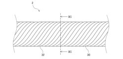
- FIG. 2C is a partial side perspective view showing the shaft portion 2 of the medical device 100
- FIG. 2D is a cross-sectional view taken along line IIC-IIC of FIG. 2C.
- the shaft portion 2 and the tip portion 1 are composed of a coil body 3 having a plurality of strands 30 wound in a hollow spiral shape.
- the coil body 3 has a first coil portion 31 corresponding to the tip portion 1 and a second coil portion 32 corresponding to the shaft portion 2.
- the first coil portion 31 is formed by thinning out at least one of the plurality of strands 30.
- FIG. 3 is a schematic side view illustrating the operation of the medical device 100 when it is inserted into a puncture hole or narrowed portion (hereinafter simply referred to as "hole H").
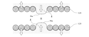
- FIG. 4A is a partial cross-sectional view illustrating the operation of the medical device 100 when it is inserted into hole H
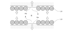
- FIG. 4B is a partial cross-sectional view illustrating the operation of the medical device 100 when it is removed from hole H.
- the coil body (multi-strand coil) 3 which is made by closely arranging and winding multiple strands (wire material) 30, acts like a screw on the inner wall (organ wall) Hw of the hole H, and therefore has superior propulsion inside the hole H compared to the tube used in the conventional dilator.
- the first coil section 31 corresponding to the tip section 1 is formed by thinning out at least one strand of the multiple strands 30.
- the gap between the wires 30 of the tip portion 1 is likely to narrow by applying a torsional force in the removal direction, reducing the outer diameter of the tip portion 1 and weakening the engagement of the inner wall Hw of the hole H with the spiral groove 4. This makes it easier to remove the medical device 100 from the hole H.
- the medical device 100 of this embodiment has improved propulsion and removal properties in the hole H.
- the rotation direction (twist direction) of the medical device 100 is in phase with the winding direction of the multiple wires 30 in the coil body 3.
- the rotation direction (twist direction) of the medical device 100 when inserted into the hole H is clockwise, it is preferable that the winding direction of the multiple wires 30 in the coil body 3 is clockwise.
- the coil body 3 is a single coil body. That is, the first coil portion 31 corresponding to the tip portion 1 and the second coil portion 31 corresponding to the shaft portion 2 are continuous. With this configuration, the torsional force when the medical device 100 is inserted into the hole H and when it is removed from the hole H is easily transmitted to the tip portion 1. Therefore, the propulsion and removal properties of the medical device 100 in the hole H are further improved.
- the number of strands 30 constituting the coil body 3 is not particularly limited.
- the number of strands 30 may be, for example, 12.
- Figures 2A to 2B show an example of a first coil section 31 formed by thinning out one of the 12 strands of strands 30.
- the thinned strands 30 are indicated by dashed lines.
- Figures 2C to 2D show an example of a second coil section 32 formed by 12 strands of strands 30.
- the thinned strands 30 are indicated by dashed lines.
- N1 /N is 0.4 or less.
- N1 /N is 1 to 4.
- these thinned strands 30 may be adjacent or non-adjacent.
- the thinned strands 30 may be two adjacent strands 30, or may be a total of two strands 30 thinned out so that there are strands 30 between each other.
- the end of the wire 30 may be present at the boundary between the second coil portion 32 and the first coil portion 31.
- the wire 30 may be, for example, a solid wire or a stranded wire having a structure in which multiple strands are twisted together.
- the rigidity of a solid wire is higher than that of a stranded wire.
- the diameter may be, for example, about 0.2 mm.
- the stranded wire may be formed by twisting together 5 to 8 strands of wire with a diameter of about 0.05 mm.
- the medical device 100 of this embodiment can be manufactured, for example, by the following method. First, multiple strands of wire 30 are wound around a core material having a long portion with a constant outer diameter corresponding to the second coil portion 32 (shaft portion 2) and a conical portion with an outer diameter that decreases toward the tip corresponding to the first coil portion 31 (tip portion 1). At this time, at least one strand of the multiple strands of wire 30 is thinned out in the portion corresponding to the first coil portion 31 to form a hollow spiral coil body 3. In this manner, the medical device 100 is obtained.
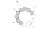
- Fig. 5A is a partial side perspective view showing the distal end portion 1 of the medical device 101 of Modification 1
- Fig. 5B is a VA-VA cross-sectional view of Fig. 5A
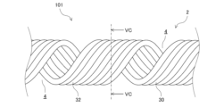
- Fig. 5C is a partial side perspective view showing the shaft portion 21 of the medical device 101 of Modification 1
- Fig. 5D is a VC-VC cross-sectional view of Fig. 5C.
- the medical device 101 of Modification 1 has the same configuration as the above-mentioned medical device 100, except that in addition to the first coil portion 31 corresponding to the distal end portion 1, the second coil portion 32 corresponding to the shaft portion 2 is also formed by thinning out at least one of the multiple strands 30.
- both the first coil portion 31 corresponding to the tip portion 1 and the second coil portion 32 corresponding to the shaft portion 2 are formed by thinning out at least one of the multiple strands 30, so that the spiral grooves 4 are present throughout the entire medical device 101 and the number of spiral grooves 4 is increased. Therefore, when inserting the medical device 101 into the hole H, the outer diameter of the entire medical device 101 is expanded by applying a twisting force in the insertion direction, and the inner wall Hw of the hole H bites into each of the increased spiral grooves 4, making it easier to insert the medical device 101 into the hole H.
- the medical device 101 of the first modification has improved propulsion and removal properties in the hole H of the medical device 101.
- the number of thinned strands 30 is not particularly limited, but when the number of thinned strands 30 in the second coil portion 32 is defined as N2 , it is preferable that N1 > N2 is satisfied. That is, it is preferable that the number N1 of thinned strands 30 in the first coil portion 31 is larger than the number N2 of thinned strands 30 in the second coil portion 32.
- the flexibility of the tip portion 1 is higher than the flexibility of the shaft portion 2, so that the propulsion of the tip portion 1 in the hole H is improved.
- the rigidity of the shaft portion 2 is higher than the rigidity of the tip portion 1, so that the deterioration of torque transmissibility can be suppressed.
- the number N1 of thinned strands 30 in the first coil portion 31 may be 3 to 4
- the number N2 of thinned strands 30 in the second coil portion 32 may be 1 to 2.
- ends of the strands 30 may be present at the boundary between the second coil portion 32 and the first coil portion 31.
- the number N1 of strands 30 thinned out in the first coil portion 31 may be equal to the number N2 of strands 30 thinned out in the second coil portion 32.
- the coil body 3 which is a single coil body, is formed by thinning out at least one strand out of the multiple strands 30. This configuration also improves the propulsion and removal properties of the medical device 101 in the hole H.
- the medical device 101 since there is no need to change the number of strands 30 to be thinned out between the first coil portion 31 and the second coil portion 32, the medical device 101 can be easily manufactured.
- the number of strands 30 thinned out in the coil body 3 is not particularly limited, but when the number of strands 30 thinned out in the coil body 3 is defined as N C , it is preferable that N C /N is 0.4 or less. With this configuration, it is possible to prevent the rigidity of the medical device 101 from decreasing too much. For example, when the number N of the strands 30 is 12, the number N C of strands 30 thinned out in the coil body 3 may be 1 to 4.
- FIGS. 5A-5B show an example of a first coil section 31 formed by thinning out two adjacent strands out of the twelve strands of wire 30.
- FIGS. 5C-5D show an example of a second coil section 32 formed by thinning out four adjacent strands out of the twelve strands of wire 30.
- the thinned strands 30 are shown by dashed lines.
- these strands 30 may be adjacent or non-adjacent.
- the strands 30 thinned out in the second coil portion 32 may be two adjacent strands 30, or may be a total of two strands 30 thinned out so that there are strands 30 between each other.
- the medical device 101 of the first modified example can be manufactured, for example, by the following method.
- a plurality of strands of wire 30 are wound around a core material having a long portion with a constant outer diameter corresponding to the second coil portion 32 (shaft portion 2) and a conical portion with an outer diameter that decreases toward the tip corresponding to the twelfth coil portion 31 (tip portion 1).
- at least one of the plurality of strands of wire 30 is thinned out in the portion corresponding to the first coil portion 31 and the portion corresponding to the second coil portion 32 to form a hollow spiral coil body 3. In this manner, the medical device 101 is obtained.
- [Modification 2] 6 is a schematic side view showing the structure of a medical device 102 of Modification 2.
- the medical device 102 of Modification 2 has a similar structure to the above-described medical devices 100 and 101, except that the diameter of the multiple strands 301 constituting the coil body 3 gradually decreases from the second coil portion 32 to the first coil portion 31.
- the flexibility of the tip portion 1 is greater than that of the shaft portion 2, improving the propulsion of the tip portion 1 in the hole H.
- the rigidity of the shaft portion 2 is greater than that of the tip portion 1, preventing a decrease in torque transmission.
- wire material described for wire 30 can be used as wire 301.
- the wire 301 at the base end of the second coil portion 32 is defined as R2 and the diameter of the wire 301 at the tip end of the first coil portion 31 is defined as R1 , the wire 301 may satisfy 0.1 ⁇ R1 / R2 ⁇ 0.7. With this configuration, it is possible to achieve both flexibility of the tip portion 1 and rigidity of the shaft portion 2.
- FIG. 6 illustrates a medical device 102 that is composed of a coil body 3, which is a single coil body formed by thinning out one of the multiple strands 301.
- the medical device 102 is not limited to the example shown in FIG. 6. In the medical device 102, only the first coil section 31 corresponding to the tip section 1 may be formed by thinning out at least one of the multiple strands 301.
- both the first coil section 31 corresponding to the tip section 1 and the second coil section 32 corresponding to the shaft section 2 may be formed by thinning out at least one of the multiple strands 301, and the number of strands 301 thinned out in the first coil section 31 and the number of strands 301 thinned out in the second coil section 32 may be equal to or different from the number of strands 301 thinned out in the first coil section 31.
- the number of strands 301 thinned out in the first coil section 31 may be greater than the number of strands 301 thinned out in the second coil section 32.
- the shaft portion 2 may have an outer diameter that decreases toward the tip.
- a medical device 102 can be manufactured, for example, by the following method. First, a core material having a long portion with a constant outer diameter corresponding to the second coil portion 32 (shaft portion 2) and a conical portion with a decreasing outer diameter toward the tip corresponding to the twelfth coil portion 31 (tip portion 1) is wound with a plurality of strands 301 such that the diameter of the strands 301 decreases from the second coil portion 32 toward the first coil portion 31.
- a medical device 102 having a shaft portion 2 with an outer diameter that decreases toward the tip is obtained.
- the shaft portion 2 may have an inner diameter that increases toward the tip.
- a medical device 102 can be manufactured, for example, by the following method. First, the above-mentioned multiple strands 30 are wound around a core material having a long portion with a constant outer diameter corresponding to the second coil portion 32 (shaft portion 2) and a conical portion with an outer diameter that decreases toward the tip corresponding to the first coil portion 31 (tip portion 1). At this time, at least one strand of the multiple strands 30 is thinned out in the portion corresponding to the first coil portion 31 (and, if necessary, the portion corresponding to the second coil portion 32) to form a hollow spiral coil body.
- the obtained coil body is subjected to chemical treatment, polishing, or the like to gradually reduce the diameter of the strands 30 from the second coil portion 32 toward the first coil portion 31.
- the strands 30 are changed into strands 301.
- a medical device 102 having a shaft portion 2 with an inner diameter that increases toward the tip is obtained.
- the medical device is used as a dilator, but the medical device of the present invention is not limited to use as a dilator, and may be applied to catheters such as penetrating catheters and guiding catheters.
Landscapes
- Health & Medical Sciences (AREA)
- Life Sciences & Earth Sciences (AREA)
- Animal Behavior & Ethology (AREA)
- Engineering & Computer Science (AREA)
- Anesthesiology (AREA)
- Biomedical Technology (AREA)
- Heart & Thoracic Surgery (AREA)
- Hematology (AREA)
- General Health & Medical Sciences (AREA)
- Public Health (AREA)
- Veterinary Medicine (AREA)
- Pulmonology (AREA)
- Biophysics (AREA)
- Vascular Medicine (AREA)
- Media Introduction/Drainage Providing Device (AREA)
Abstract
Description
図5Aは、変形例1の医療器具101の先端部1を示す部分側面斜視図であって、図5Bは、図5AのVA-VA断面図である。図5Cは、変形例1の医療器具101のシャフト部21を示す部分側面斜視図であって、図5Dは、図5CのVC-VC断面図である。変形例1の医療器具101は、先端部1に相当する第1コイル部31に加えて、シャフト部2に相当する第2コイル部32も、複数の素線30のうちの少なくとも1条を間引くことにより形成されていることを除き、上述した医療器具100と同様の構成を有する。
図6は、変形例2の医療器具102の構造を示す概略側面図である。変形例2の医療器具102は、コイル体3を構成する複数の素線301が、第2コイル部32から第1コイル部31に向かって徐々に直径が減少していることを除き、上述した医療器具100及び101と同様の構成を有する。
1 先端部
2 シャフト部
3 コイル体
31 第1コイル部
32 第2コイル部
30、301 素線
4 螺旋溝
H 孔
Hw 内壁
Claims (8)
- シャフト部と、前記シャフト部の一端に位置し、前記シャフト部から離れる方向に向かって外径が縮小している先端部とを備え、
前記シャフト部及び前記先端部が、中空螺旋状に巻回された複数の素線を有するコイル体から構成され、
前記コイル体が、前記先端部に相当する第1コイル部と、前記シャフト部に相当する第2コイル部と、を有し、
前記第1コイル部が、前記複数の素線のうちの少なくとも1条を間引くことにより形成されている、医療器具。 - 前記第2コイル部が、前記複数の素線のうちの少なくとも1条を間引くことにより形成されている、請求項1に記載の医療器具。
- 前記第1コイル部において間引かれた前記素線の数をN1と定義し、前記第2コイル部において間引かれた前記素線の数をN2と定義したとき、N1>N2を満たす、請求項2に記載の医療器具。
- 前記コイル体が、単一のコイル体である、請求項1から3のいずれか一項に記載の医療器具。
- 前記複数の素線の数をNと定義し、前記第1コイル部において間引かれた前記素線の数をN1と定義したとき、N1/Nが0.4以下を満たす、請求項1に記載の医療器具。
- 前記コイル体が、単一のコイル体であって、前記複数の素線のうちの少なくとも1条を間引くことにより形成されている、請求項1に記載の医療器具。
- 前記複数の素線の数をNと定義し、前記コイル体において間引かれた前記素線の数をNCと定義したとき、NC/Nが0.4以下を満たす、請求項6に記載の医療器具。
- 前記コイル体が、単一のコイル体であり、
前記複数の素線が、前記第2コイル部から前記第1コイル部に向かって徐々に直径が減少している、請求項1に記載の医療器具。
Priority Applications (3)
| Application Number | Priority Date | Filing Date | Title |
|---|---|---|---|
| JP2024575951A JPWO2024166254A1 (ja) | 2023-02-08 | 2023-02-08 | |
| PCT/JP2023/004193 WO2024166254A1 (ja) | 2023-02-08 | 2023-02-08 | 医療器具 |
| US19/272,692 US20250339651A1 (en) | 2023-02-08 | 2025-07-17 | Medical instrument |
Applications Claiming Priority (1)
| Application Number | Priority Date | Filing Date | Title |
|---|---|---|---|
| PCT/JP2023/004193 WO2024166254A1 (ja) | 2023-02-08 | 2023-02-08 | 医療器具 |
Related Child Applications (1)
| Application Number | Title | Priority Date | Filing Date |
|---|---|---|---|
| US19/272,692 Continuation US20250339651A1 (en) | 2023-02-08 | 2025-07-17 | Medical instrument |
Publications (1)
| Publication Number | Publication Date |
|---|---|
| WO2024166254A1 true WO2024166254A1 (ja) | 2024-08-15 |
Family
ID=92262196
Family Applications (1)
| Application Number | Title | Priority Date | Filing Date |
|---|---|---|---|
| PCT/JP2023/004193 Ceased WO2024166254A1 (ja) | 2023-02-08 | 2023-02-08 | 医療器具 |
Country Status (3)
| Country | Link |
|---|---|
| US (1) | US20250339651A1 (ja) |
| JP (1) | JPWO2024166254A1 (ja) |
| WO (1) | WO2024166254A1 (ja) |
Citations (4)
| Publication number | Priority date | Publication date | Assignee | Title |
|---|---|---|---|---|
| JP2007098120A (ja) * | 2005-09-06 | 2007-04-19 | Fmd:Kk | 医療用処置具及びその回転操作装置並びに医療用処置装置 |
| WO2018181179A1 (ja) * | 2017-03-30 | 2018-10-04 | テルモ株式会社 | 親水性部材と疎水性部材とを積層させた医療機器 |
| WO2020059121A1 (ja) * | 2018-09-21 | 2020-03-26 | 朝日インテック株式会社 | ダイレータ |
| WO2020084677A1 (ja) * | 2018-10-23 | 2020-04-30 | 朝日インテック株式会社 | 中空コイル、ダイレータ、および、ガイドワイヤ |
-
2023
- 2023-02-08 JP JP2024575951A patent/JPWO2024166254A1/ja active Pending
- 2023-02-08 WO PCT/JP2023/004193 patent/WO2024166254A1/ja not_active Ceased
-
2025
- 2025-07-17 US US19/272,692 patent/US20250339651A1/en active Pending
Patent Citations (4)
| Publication number | Priority date | Publication date | Assignee | Title |
|---|---|---|---|---|
| JP2007098120A (ja) * | 2005-09-06 | 2007-04-19 | Fmd:Kk | 医療用処置具及びその回転操作装置並びに医療用処置装置 |
| WO2018181179A1 (ja) * | 2017-03-30 | 2018-10-04 | テルモ株式会社 | 親水性部材と疎水性部材とを積層させた医療機器 |
| WO2020059121A1 (ja) * | 2018-09-21 | 2020-03-26 | 朝日インテック株式会社 | ダイレータ |
| WO2020084677A1 (ja) * | 2018-10-23 | 2020-04-30 | 朝日インテック株式会社 | 中空コイル、ダイレータ、および、ガイドワイヤ |
Also Published As
| Publication number | Publication date |
|---|---|
| US20250339651A1 (en) | 2025-11-06 |
| JPWO2024166254A1 (ja) | 2024-08-15 |
Similar Documents
| Publication | Publication Date | Title |
|---|---|---|
| JP7431001B2 (ja) | ダイレータ | |
| JP6997306B2 (ja) | ダイレータ | |
| WO2021064955A1 (ja) | 医療用管状体 | |
| JP7162957B2 (ja) | カテーテル | |
| JP2002275774A (ja) | 医療用チューブ体、バルーンカテーテルおよび医療用ガイドワイヤ | |
| JP7457579B2 (ja) | ダイレータ | |
| WO2020059121A1 (ja) | ダイレータ | |
| WO2024166254A1 (ja) | 医療器具 | |
| JP7330129B2 (ja) | ダイレータ | |
| JPWO2017175373A1 (ja) | 軟性マニピュレータ | |
| WO2022049688A1 (ja) | ダイレータ | |
| JP6637991B2 (ja) | 医療機器 | |
| JP7532573B2 (ja) | ガイドワイヤ | |
| WO2024038892A1 (ja) | 医療用コイル体 | |
| JP2022190735A (ja) | コイル体 | |
| JP6588679B1 (ja) | ダイレータ | |
| JP2024039784A (ja) | 医療デバイス | |
| WO2024203196A1 (ja) | カテーテルセット | |
| JP2024144166A (ja) | カテーテルセット |
Legal Events
| Date | Code | Title | Description |
|---|---|---|---|
| 121 | Ep: the epo has been informed by wipo that ep was designated in this application |
Ref document number: 23921086 Country of ref document: EP Kind code of ref document: A1 |
|
| ENP | Entry into the national phase |
Ref document number: 2024575951 Country of ref document: JP Kind code of ref document: A |
|
| WWE | Wipo information: entry into national phase |
Ref document number: 2024575951 Country of ref document: JP |
|
| NENP | Non-entry into the national phase |
Ref country code: DE |
|
| 122 | Ep: pct application non-entry in european phase |
Ref document number: 23921086 Country of ref document: EP Kind code of ref document: A1 |