WO2024166153A1 - 保護制御装置および保護制御システム - Google Patents
保護制御装置および保護制御システム Download PDFInfo
- Publication number
- WO2024166153A1 WO2024166153A1 PCT/JP2023/003720 JP2023003720W WO2024166153A1 WO 2024166153 A1 WO2024166153 A1 WO 2024166153A1 JP 2023003720 W JP2023003720 W JP 2023003720W WO 2024166153 A1 WO2024166153 A1 WO 2024166153A1
- Authority
- WO
- WIPO (PCT)
- Prior art keywords
- protection
- current
- lines
- unit
- control device
- Prior art date
- Legal status (The legal status is an assumption and is not a legal conclusion. Google has not performed a legal analysis and makes no representation as to the accuracy of the status listed.)
- Ceased
Links
Images




Classifications
-
- H—ELECTRICITY
- H02—GENERATION; CONVERSION OR DISTRIBUTION OF ELECTRIC POWER
- H02H—EMERGENCY PROTECTIVE CIRCUIT ARRANGEMENTS
- H02H3/00—Emergency protective circuit arrangements for automatic disconnection directly responsive to an undesired change from normal electric working condition with or without subsequent reconnection ; integrated protection
- H02H3/02—Details
-
- H—ELECTRICITY
- H02—GENERATION; CONVERSION OR DISTRIBUTION OF ELECTRIC POWER
- H02H—EMERGENCY PROTECTIVE CIRCUIT ARRANGEMENTS
- H02H3/00—Emergency protective circuit arrangements for automatic disconnection directly responsive to an undesired change from normal electric working condition with or without subsequent reconnection ; integrated protection
- H02H3/26—Emergency protective circuit arrangements for automatic disconnection directly responsive to an undesired change from normal electric working condition with or without subsequent reconnection ; integrated protection responsive to difference between voltages or between currents; responsive to phase angle between voltages or between currents
- H02H3/28—Emergency protective circuit arrangements for automatic disconnection directly responsive to an undesired change from normal electric working condition with or without subsequent reconnection ; integrated protection responsive to difference between voltages or between currents; responsive to phase angle between voltages or between currents involving comparison of the voltage or current values at two spaced portions of a single system, e.g. at opposite ends of one line, at input and output of apparatus
-
- H—ELECTRICITY
- H02—GENERATION; CONVERSION OR DISTRIBUTION OF ELECTRIC POWER
- H02J—ELECTRIC POWER NETWORKS; CIRCUIT ARRANGEMENTS OR SYSTEMS FOR SUPPLYING OR DISTRIBUTING ELECTRIC POWER; SYSTEMS FOR STORING ELECTRIC ENERGY
- H02J13/00—Circuit arrangements for providing remote monitoring or remote control of equipment in a power distribution network
Definitions
- An embodiment of the present invention relates to a protection control device and a protection control system.
- a differential current is a current that is detected by physical calculation when a system fault or fault occurs.
- a differential current element calculates the differential current (e.g., software, etc.), and when it detects that the differential current is above a threshold, it determines that an fault has occurred and outputs a circuit breaker opening signal.
- the differential current element constantly captures the current amounts of all circuits (e.g., all transmission lines) connected to the busbar and calculates the differential current.
- conventional busbar protection and control devices utilize the principle that a differential current is not generated in a normal state but is generated in the event of an fault, and determine that an fault has occurred in the busbar section when an fault is detected by the differential current element.
- the differential current element could detect an accident when an abnormality occurred in one of the total lines of current being taken in, due to an abnormality in the input circuit or a temporary abnormality (single fault) caused by the control system, which could occur within the device.
- an erroneously detected differential current could cause the protection control device to erroneously detect an accident, leading to malfunctions such as circuit breaker opening control.
- the problem that this invention aims to solve is to provide a protection control device and a protection control system that can more appropriately avoid false detection of accidents.
- the protection and control device of the embodiment has an AD conversion unit and a control unit.
- the AD conversion unit digitally converts the current value from a current transformer provided on each line in the busbar section of the power system.
- the control unit performs cutoff control for each line when it is determined that an accident has occurred in the power system based on the current value of each line digitally converted by the AD conversion unit. Furthermore, the control unit determines that an accident has occurred in the power system when an accident is detected by a differential current element based on the current value of each line and when two or more of the lines have a current change range equal to or greater than a threshold value.
- FIG. 1 is a diagram showing an example of a functional configuration of a protection and control system 1 to which a protection and control device 100 of a first embodiment is applied.
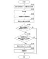
- 4 is a flowchart showing an example of processing executed by the protection and control device 100 of the first embodiment.
- FIG. 11 is a diagram showing an example of the functional configuration of a protection and control system 1A to which a protection and control device 100A of a second embodiment is applied. 11 is a flowchart showing an example of processing executed by a protection and control device 100A of the second embodiment.
- FIG. 13 is a diagram showing an example of a protection and control system 1B according to a third embodiment.
- FIG. 13 illustrates an example of the configuration of an MU 200 according to a third embodiment.
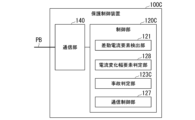
- FIG. 13 is a diagram showing an example of the configuration of a protection and control device 100B according to a third embodiment.
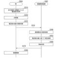
- FIG. 13 is a sequence diagram showing an example of processing executed by the protection and control system 1B of the third embodiment.
- FIG. 13 illustrates an example of the configuration of an MU 200A according to a fourth embodiment.
- FIG. 13 is a diagram showing an example of the configuration of a protection and control device 100C according to a fourth embodiment.
- FIG. 13 is a sequence diagram illustrating an example of processing executed by the protection and control system of the fourth embodiment.
- FIG. 13 is a diagram showing an example of the configuration of an MU 200B according to the fifth embodiment.
- FIG. 13 is a diagram showing an example of the configuration of a protection and control device 100D according to a fifth embodiment.
- FIG. 13 is a sequence diagram illustrating an example of processing executed by the protection and control system of the fifth embodiment.
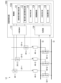
- FIG. 1 is a diagram showing an example of a functional configuration of a protection control system 1 to which a protection control device 100 of a first embodiment is applied.
- the protection control system 1 includes, for example, a power transmission line 20 connected to a bus 10 of a power system, a current transformer 30, a circuit breaker 40, a disconnecting switch 50, and a protection control device 100.
- a plurality of power transmission lines 20-1, 20-2, ..., 20-n are connected to the bus 10, and current transformers 30-1, 30-2, ..., 30-n, circuit breakers 40-1, 40-2, ..., 40-n, and disconnecting switches 50-1, 50-2, ..., 50-n are provided in association with each of the power transmission lines 20.
- the power transmission lines 20-1, 20-2, ..., 20-n will be simply referred to as "power transmission lines 20" except when each of the power transmission lines 20-1, 20-2, ..., 20-n is described separately.
- the power transmission line 20 relays power between bus bars and AC power sources, and transmits power to supply it to devices and facilities that use power.
- the power transmitted by the power transmission line 20 is assumed to be three-phase AC.
- the power transmission line 20 has three power lines for transmitting each phase of the three-phase AC power, and transmits the power of each phase.
- the current transformer 30 converts the large current of each phase of the power transmission line 20 into a measurable small current.
- the current transformer 30 converts the large current into a small current, for example, by dropping the voltage using a resistor or by using a wound-type current transformer.
- the current transformer 30 outputs the current waveform (analog waveform) for each phase after conversion into a small current to the protection and control device 100.
- the current transformer 30 is connected to the protection and control device 100 by, for example, a metal cable (current circuit) or the like.
- the circuit breaker 40 switches the power flowing through the portion of the power transmission line 20 where the circuit breaker 40 is installed to a three-phase cut-off state in response to a control signal (e.g., a trip signal) from the protection and control device 100.
- the circuit breaker 40 may also output status information to the protection and control device 100 indicating whether or not the power flowing through the power transmission line 20 where the circuit breaker 40 is installed is being cut off (whether or not it is in a cut-off state).
- the status information may include status information for each phase.
- the disconnector 50 cuts off the supply of power from the bus 10 to the power transmission line 20 in response to a control signal from the protection and control device 100. For example, the disconnector 50 temporarily cuts off the supply of power to the power transmission line 20 in a non-accident situation such as during maintenance.
- the disconnector 50 may also output status information to the protection and control device 100 indicating whether or not the power flowing through the corresponding power transmission line 20 is being cut off (whether or not it is in a cut-off state).
- the protection and control device 100 acquires power information on the power supplied to the busbar section to be protected, and judges whether or not an accident such as a short circuit or a ground fault has occurred in the power system based on the acquired power information.
- the power information is information on the power supplied to the section of the transmission line 20, and is, for example, information indicating the current value of the power supplied to that section.
- the protection and control device 100 cuts off (opens) the circuit breaker 40 installed at the location where it is determined that the accident has occurred, and isolates the power equipment or system where the accident has occurred, thereby eliminating the accident, suppressing its expansion, and protecting the busbar 10 to ensure the sound operation of the power system.
- the protection and control device 100 in the first embodiment uses the current value of all circuits (all transmission lines) in a situation where the voltage amount of the busbar 10 is not acquired, thereby avoiding erroneous detection of an accident and malfunction of cutoff control such as circuit breaker opening control.
- the protection and control device 100 includes, for example, an AD conversion unit 110 and a control unit 120.
- the AD conversion unit 110 and the control unit 120 are realized by, for example, a hardware processor such as a CPU (Central Processing Unit) executing a program (software). Some or all of these components may be realized by hardware (including circuitry) such as an LSI (Large Scale Integration), ASIC (Application Specific Integrated Circuit), or FPGA (Field-Programmable Gate Array), or may be realized by a combination of software and hardware.
- the program is stored in advance in a storage device such as a flash memory (a storage device with a non-transitory storage medium).
- the AD conversion unit 110 inputs the analog waveform of the current value from the current transformer 30 as power information, and converts the input analog waveform into digital data.
- the control unit 120 includes, for example, a differential current element detection unit 121, a current change width element detection unit 122, an accident determination unit 123, and a protection control unit 124.
- the differential current element detection unit 121 constantly monitors the current values (current information) of all lines converted by the AD conversion unit 110, and detects accidents by the differential current.
- the differential current element detection unit 121 operates a differential current element (DIF), which is software (application program) that calculates differential currents, compares the current values of each line (each power transmission line 20) input from the AD conversion unit 110, and detects an accident when the difference in the current values (differential current) is equal to or greater than a threshold value (first threshold value).
- the differential current element detection unit 121 may also detect an accident when the sum of the current values of each line exceeds a predetermined range. The detection of an accident by comparing the above-mentioned differential current with a threshold value may be rephrased as "the differential current element operates.”
- the current change width element detection unit 122 detects the change width (current change width ( ⁇ I)) of the current amount of each line in a predetermined time from the current values of all lines converted by the AD conversion unit 110.
- the current change width element detection unit 122 operates a current change width element, which is software (application program) that calculates the current change width, and detects the number of lines for which the current change width is equal to or greater than a threshold value (second threshold value) for each current change line.
- the current change width element operates.
- the first threshold value and the second threshold value may be fixed values, or variable values may be set according to the protection control system configuration (e.g., the number of lines) and operating conditions.
- the second threshold value may be a value set for each line.
- the accident determination unit 123 determines whether or not an accident has occurred in the power system in the protected section based on the detection results of the differential current element detection unit 121 and the current change width element detection unit 122. For example, the accident determination unit 123 determines that an accident has occurred in the power system when an accident is detected in the differential current element by the differential current element detection unit 121 and the number of lines in which the current change width detected by the current change width element detection unit 122 is equal to or greater than the threshold is two or more. The accident determination unit 123 may also determine that a busbar accident has been detected when, for example, the operation of the differential current element and the operation of two lines of the current change width element are established.
- the current change width is equal to or greater than the threshold for only one line, so it is not determined that a system accident has occurred.
- the threshold for at least two lines is equal to or greater than the threshold, it is determined that an accident has occurred in the power system (bus bar 10 or transmission line 20), allowing for more appropriate accident determination.
- the protection control unit 124 transmits a trip signal to the circuit breaker 40 installed in the section to be protected (e.g., the bus section) and performs control (circuit breaker opening control) to open the circuit breaker 40 and cut off the transmission of power in the transmission line 20.
- the protection control unit 124 may transmit a trip signal only to the circuit breaker 40 corresponding to the line where the current change width is equal to or greater than a threshold, and perform control to cut off the power flowing through the transmission line 20 to which the circuit breaker 40 is connected.
- the power supply can be continued without cutting off the power of the transmission line 20.
- the protection control unit 124 may also perform the above-mentioned shutoff control on the disconnector 50 instead of (or in addition to) the circuit breaker 40.
- the protection control unit 124 may also control the circuit breaker 40 so that power flows through the power transmission line 20 when the fault is resolved.
- Fig. 2 is a flowchart showing an example of processing executed by the protection and control device 100 of the first embodiment. Note that the processing in Fig. 2 may be repeatedly executed at predetermined intervals while the protection and control system 1 is in operation.
- the protection and control device 100 acquires a current value (analog waveform) from a current transformer 30 provided on each transmission line 20 connected to the bus bar 10 (step S110).
- the AD conversion unit 110 performs analog-to-digital conversion on the acquired current value (step S120).
- the differential current element detection unit 121 performs a calculation process of the differential current based on the current values of all the lines of the protection and control system 1 (step S130).
- the current change width element detection unit 122 performs a calculation process of the current change width for each line of the protection and control system 1 (step S140).
- the accident determination unit 123 determines whether an accident has been detected in the differential current element (whether the differential current element has operated) based on the result calculated by the process of step S130 (step S150). If it is determined that an accident has been detected in the differential current element (the differential current element has operated), the accident determination unit 123 determines whether there are two or more lines among all the lines whose current change width is equal to or greater than the threshold (whether there are two or more lines whose current change width elements have operated) based on the result calculated by step S140 (step S160). If it is determined that there are two or more lines, the accident determination unit 123 determines that an accident has occurred in the power system to be protected (step S170).
- the protection control unit 124 transmits a trip signal to cut off the flow of power supplied to the transmission line 20 to be protected, and performs protection control (step S180). This ends this flowchart. Furthermore, if it is determined in the processing of step S150 that no accident was detected in the differential current element (the differential current element did not operate), or if it is determined in the processing of step S170 that there are not two or more lines in which the current change range is equal to or greater than the threshold value, the processing of this flowchart ends.
- the fault is detected by the differential current element and a large change occurs in the current value in multiple lines. Therefore, by detecting an fault when the differential current element detects an fault and there are two or more lines where the current change range exceeds a threshold, it is possible to perform an appropriate fault determination due to an abnormality in the current value. Therefore, it is possible to avoid a malfunction of the cutoff control by the protection and control device 100. Furthermore, according to the first embodiment, even if the power information from the transmission line 20 does not include a voltage value, it is possible to perform a more accurate system fault detection using the current value.
- the second embodiment differs from the first embodiment in that the protection control device acquires status information from the circuit breaker 40 and the disconnector 50, and performs fault detection using a differential current element or a current change width element for a line selected based on the acquired status information, etc.
- the following mainly describes the above-mentioned differences.
- FIG. 3 is a diagram showing an example of the functional configuration of a protection and control system 1A to which a protection and control device 100A of the second embodiment is applied. Note that in the protection and control system 1A, components similar to those in the protection and control system 1 of the first embodiment are given the same reference numerals, and detailed explanations are omitted here. The same applies to the other embodiments described below.
- the protection control system 1 includes, for example, a power transmission line 20 connected to a busbar 10 of a power system, a current transformer 30, a circuit breaker 40, a disconnector 50, and a protection control device 100A.
- the protection control device 100A includes, for example, an AD conversion unit 110, a control unit 120A, and an acquisition unit 130.
- the control unit 120A also includes, for example, a differential current element detection unit 121, a current change width element detection unit 122, an accident determination unit 123, a protection control unit 124, a state determination unit 125, and a line selection unit 126.
- the protection control device 100A differs from the busbar protection of the first embodiment in that it has a control unit 120A instead of the control unit 120, and in that it has an acquisition unit 130.
- the control unit 120A also differs from the control unit 120 in that it has a state determination unit 125 and a line selection unit 126. Therefore, the following explanation will mainly focus on the differences mentioned above.
- the acquisition unit 130 acquires status information from at least one of the circuit breaker 40 and the disconnector 50.
- the acquisition unit 130 may acquire status information at a predetermined interval, or may inquire about the status of the circuit breaker 40 and the disconnector 50 and acquire the status information as a result.
- the status determination unit 125 determines, for each line (power transmission line 20), whether or not the power flowing through the line has been interrupted based on the status information acquired by the acquisition unit 130.
- the line selection unit 126 selects a line for which an accident is to be detected using the current change width element from among the lines that are not cut off by the state determination unit 125. For example, the line selection unit 126 may randomly select multiple lines from the lines that are not cut off, or may select the other line that corresponds to the cut off line based on the relationship between the lines, in which the other line is always in an uncut state when one line is in a cut off state. The line selection unit 126 may also select a line based on information set in advance by a user (administrator, worker, etc.).
- the line selection unit 126 may also adjust the number of lines to be selected based on the current processing load (operating status) of the protection and control device 100A or the processing load predicted for the near future. For example, the line selection unit 126 can reduce the processing load by reducing the number of lines to be selected as the processing load increases.
- the line selection unit 126 may also set a priority for each line in advance, and select a predetermined number of lines from among the lines that are not blocked, starting with those with the highest priority. For example, the priority is set to be higher the easier it is to accurately obtain the current change range. The ease of obtaining an accurate current change range includes, for example, a situation in which the change in current of the line under normal conditions is small, and a situation in which the change in current under abnormal conditions is large. Alternatively (or in addition), the priority may be set to be higher for lines included in the protected bus section that are more likely to be affected by erroneous detection of an accident.
- the differential current element detection unit 121 performs accident detection processing using differential current elements, for example, using the current value of an uninterrupted line.
- the current change width element detection unit 122 calculates the current change width for two or more lines selected by the line selection unit 126.
- the current change width element detection unit 122 may also determine whether there are two or more lines in which the detected current change width is equal to or greater than a threshold. If a priority is set for the lines selected by the line selection unit 126, the current change width element detection unit 122 may determine whether the current change width is equal to or greater than a threshold in order of priority, and may terminate subsequent processing when there are two lines in which the current change width is equal to or greater than the threshold. This reduces the processing load of the current change width element detection unit 122 and enables the accident determination unit 123 to perform an accident determination more quickly.
- Fig. 4 is a flowchart showing an example of processing executed by the protection and control device 100A of the second embodiment.
- the processing shown in Fig. 4 differs from the processing executed by the protection and control device 100 of the first embodiment shown in Fig. 2 in that processing of steps S100 to S104 is added. Therefore, the following description will mainly focus on the processing of steps S100 to S104. Note that the processing of steps S100 to S104 may be executed before the processing of steps S110 to S180 is repeatedly executed.
- the acquisition unit 130 of the protection and control device 100A acquires status information from at least one of the circuit breakers 40 or disconnectors 50 provided on each line (power transmission line 20) connected to the bus 10 (step S100).
- the state determination unit 125 determines whether each line is in an interrupted state based on the status information (step S102).
- the line selection unit 126 selects a line for which the current change width and the like are to be calculated based on the processing result of step S102 (step S104).
- the protection and control device 100A executes the processing from step S110 onwards for the selected line.
- the protection and control device 100A may perform the processing from step S110 to S130 on all lines of the protection and control system 1, and may limit the processing from step S140 onwards to the line selected by the processing of step S104.
- the second embodiment described above not only achieves the same effects as the first embodiment, but also acquires status information for each line, selects two or more lines from all lines in the protection control system 1A based on the acquired status information, and performs accident determination for the selected lines based on the differential current element and the current change width element. This reduces the processing load compared to performing accident determination based on all lines, and enables more efficient and rapid accident determination to be achieved.
- FIG. 5 is a diagram showing an example of a protection control system 1B of the third embodiment.
- a protection control system 1B is shown to which a communication network of a process bus PB for the purpose of reducing the number of lines between a protection control device 100B and a primary device such as a current transformer 30 is applied.
- the process bus PB is, for example, a transmission line (signal line) of a process bus network that performs digital communication by a communication protocol conforming to IEC 61850, which is an international standard.
- the process bus PB is, for example, an optical cable for exchanging digital data by optical communication.
- a merging unit (MU) 200 is installed at a position (for example, near (within a predetermined distance from) the primary device) associated with a primary device (for example, a current transformer 30 or a circuit breaker 40) as shown in FIG. 5.
- the MU 200 is an example of a "processing device".
- the MU 200 has a function of converting analog values of current or voltage generated in the power system into digital values, and controlling the circuit breaker 40 and the like in response to a command (trip information) from the protection and control device 100 in the event of an accident in the bus bar 10, the transmission line 20, etc.
- the current transformer 30 and the MU 200 are connected by, for example, a metal cable
- the MU 200 and the protection and control device 100B are connected by a process bus PB.
- MUs 200-1, 200-2, ..., 200-n are provided corresponding to current transformers 30-1, 30-2, ..., 30-n associated with a plurality of power transmission lines 20-1, 20-2, ..., 20-n. Since the functions of each are similar, MUs 200-1, 200-2, ..., 200-n will be simply referred to as "MU 200" below, except when MUs 200-1, 200-2, ..., 200-n are to be described separately.
- the protection and control system 1B can transmit power information to the protection and control device 100 through network communication using the process bus PB. This eliminates the need for an AD conversion unit on the protection and control device 100B side, and allows accident detection based on the differential current element and the current change width element to be performed using the power information input from the MU 200 via the process bus PB as is.
- a trip command to open the circuit breaker 40 is not transmitted directly from the protection and control device 100B to the circuit breaker 40, but the trip information is transmitted from the protection and control device 100B to each MU 200 via the process bus PB, and each MU 200 transmits a trip signal to the corresponding circuit breaker 40. In this way, in the third embodiment, processing can be distributed by having the MU 200 perform some of the functions of the protection and control device 100, and more efficient processing can be achieved in the entire system.
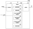
- FIG. 6 is a diagram showing an example of the configuration of the MU 200 of the third embodiment.
- the MU 200 includes, for example, an AD conversion unit 210, a control unit 220, and a communication unit 230.
- the AD conversion unit 210 and the control unit 220 are realized by, for example, a hardware processor such as a CPU executing a program (software). Some or all of these components may be realized by hardware (including circuitry) such as an LSI, ASIC, FPGA, or GPU, or may be realized by collaboration between software and hardware.
- the program may be stored in a storage device such as an HDD or flash memory (a storage device having a non-transient storage medium) in advance, or may be stored in a removable storage medium such as a DVD or CD-ROM (a non-transient storage medium), and may be installed by mounting the storage medium in a drive device.
- a storage device such as an HDD or flash memory (a storage device having a non-transient storage medium) in advance, or may be stored in a removable storage medium such as a DVD or CD-ROM (a non-transient storage medium), and may be installed by mounting the storage medium in a drive device.
- the control unit 220 is an example of a "first control unit”
- the communication unit 230 is an example of a "first communication unit”.
- the AD conversion unit 210 inputs the analog waveform of the current value from the current transformer 30 as power information, and converts the input analog waveform into digital data.
- the control unit 220 includes, for example, a communication control unit 221 and a protection control unit 222.
- the communication control unit 221 causes the power information (digital data) converted by the AD conversion unit 210 to be transmitted from the communication unit 230 to the protection control device 100B via the process bus PB.
- the communication control unit 221 also performs control so that the information transmitted from the protection control device 100B is received by the communication unit 230.
- the communication control unit 221 may also control communication (transmission and reception) with other MUs 200 and other devices connected to the process bus PB.
- the protection control unit 222 When the protection control unit 222 receives trip information (or information indicating that an accident has been detected or that cut-off control is to be performed) for outputting a trip signal to the circuit breaker 40 from the protection control device 100B via the process bus PB, the protection control unit 222 outputs a trip signal to the circuit breaker 40 to open and cut off the circuit breaker 40 associated with the MU 200.
- trip information or information indicating that an accident has been detected or that cut-off control is to be performed
- the communication unit 230 communicates with the protection and control device 100B connected to the process bus PB.
- the communication unit 230 may also communicate with other MUs 200 connected to the process bus PB.
- FIG. 7 is a diagram showing an example of the configuration of a protection control device 100B of the third embodiment.
- the protection control device 100B includes, for example, a communication unit 140 and a control unit 120B.
- the control unit 120B includes, for example, a differential current element detection unit 121, a current change width element detection unit 122, an accident determination unit 123, and a communication control unit 127.
- the communication unit 140 communicates with each MU 200 via the process bus PB.
- the current change width element detection unit 122 and the accident determination unit 123 are the same as those in the first embodiment described above, so a detailed description will be omitted here.
- the control unit 120B is an example of a "second control unit”
- the communication unit 140 is an example of a "second communication unit”.
- the communication control unit 127 controls communication with the MU 200 via the process bus PB by the communication unit 140.
- the communication control unit 127 causes the target MU 200 to transmit the result of the accident determination by the accident determination unit 123, or trip information for performing cutoff control such as circuit breaker opening control when it is determined that an accident has occurred in the power system.
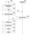
- FIG. 8 is a sequence diagram showing an example of processing executed by the protection and control system 1B of the third embodiment.
- Fig. 8 an example of processing using one MU 200 and the protection and control device 100B for convenience of explanation is explained, but similar processing is executed between each of the multiple MUs 200 present in the system and the protection and control device 100B.
- the MU 200 acquires a current value from the own line (power transmission line 20) associated with the MU 200 via the current transformer 30 (step S210), performs AD conversion on the acquired current value (step S220), and transmits the converted digital data to the protection and control device 100B via the process bus PB (step S230).
- the protection and control device 100B performs calculations of the differential current using the digital data of the current value received from the MU 200 (step S240), and performs calculations of the current change range (step S250). Next, the protection and control device 100B performs an accident determination similar to that of the first embodiment described above based on the respective calculation results of the differential current and the current change range (step S260), and transmits the accident determination result (or trip information based on the shutoff control) to the MU 200 (step S270).
- the MU 200 performs protection control for the busbar section to be protected based on the accident determination result received from the protection and control device 100B (step S280). In the process of step S280, for example, if it is determined that an accident has occurred, the MU 200 performs control to open the circuit breaker 40 installed in the busbar section to be protected to cut off the flow of power. Also, if it is determined that the accident has been resolved, the MU 200 transmits a signal to the circuit breaker 40 to release the cut-off state (information to allow power to flow through the power transmission line 20).
- the third embodiment described above not only achieves the same effects as the first embodiment, but also distributes the processing of the entire system by providing the MU200 with processing such as AD conversion of the current value (analog waveform) obtained from the power transmission line 20 and protection control, thereby reducing the load on the protection and control device 100B.
- processing such as AD conversion of the current value (analog waveform) obtained from the power transmission line 20 and protection control, thereby reducing the load on the protection and control device 100B.
- the process bus PB which is a general-purpose network, is used, it is possible to reduce the number of wires between the protection and control device 100B and the primary devices, and it is possible to suppress the equipment costs of the entire system.
- a protection control device of a fourth embodiment will be described.
- a system similar to the protection control system 1B shown in the third embodiment can be applied, but the MU 200 and the protection control device 100B each perform processing different from that in the third embodiment.
- the MU (merging unit) in the fourth embodiment will be referred to as "MU 200A” and the protection control device will be referred to as "protection control device 100C”.
- FIG. 9 is a diagram showing an example of the configuration of the MU 200A of the fourth embodiment.
- the MU 200A includes, for example, an AD conversion unit 210, a control unit 220A, and a communication unit 230.
- the control unit 220A includes, for example, a communication control unit 221, a protection control unit 222, and a current change width element detection unit 223.
- the MU 200A differs in that it has a control unit 220A instead of the control unit 220, and further differs in that the control unit 220A has a current change width element detection unit 223 compared to the control unit 220. Therefore, the following description will mainly focus on the current change width element detection unit 223.
- the control unit 220A is an example of a "first control unit".
- the current change width element detection unit 223 detects the current change width of the power transmission line 20 (own line) to which the MU 200A is connected, based on the current value (digital signal) digitally converted by the AD conversion unit 210.
- the communication control unit 221 transmits the current change width detected by the current change width element detection unit 223 from the communication unit 230 to the protection control device 100C via the process bus PB.
- the current change width element detection unit 223 may determine whether the detected current change width is equal to or greater than a threshold value.
- the communication control unit 221 transmits information indicating that the current change width is equal to or greater than the threshold value (or information indicating that the current change width element has operated) to the protection control device 100C.
- the communication control unit 221 also transmits, for example, power information or the like for causing the protection control device 100C to calculate a differential current (to cause the differential current element to operate).
- FIG. 10 is a diagram showing an example of the configuration of the protection control device 100C of the fourth embodiment.
- the protection control device 100C includes, for example, a communication unit 140 and a control unit 120C.
- the control unit 120C includes, for example, a differential current element detection unit 121, a current change width element determination unit 128, an accident determination unit 123C, and a communication control unit 127.
- the protection control device 100C of the fourth embodiment differs from the protection control device 100B of the third embodiment in that it has a current change width element determination unit 128 instead of the current change width element detection unit 122, and an accident determination unit 123C instead of the accident determination unit 123. Therefore, the following description will mainly focus on the above-mentioned differences.
- the control unit 120C is an example of a "second control unit".
- the current change width element determination unit 128 determines whether or not there are two or more lines whose current change width is equal to or greater than the threshold value based on the current change width of each line received from the multiple MUs 200A connected via the process bus PB.
- the current change width element determination unit 128 may also determine whether or not information indicating that the current change width is equal to or greater than the threshold value (or information indicating that the current change width element has operated) has been transmitted from two or more of the multiple MUs 200A.
- the accident determination unit 123C performs an accident determination similar to that of the first embodiment based on the processing results by the differential current element detection unit 121 and the processing results by the current change width element determination unit 128.
- the accident determination unit 123C determines that an accident has occurred in the power system.
- the communication control unit 127 transmits the result of the accident determination by the accident determination unit 123C, or trip information for performing cutoff control such as circuit breaker opening control when it is determined that an accident has occurred in the power system, to the target MU 200A.
- the protection control unit 222 of the MU 200A sends a trip signal to the circuit breaker 40 when it is necessary to cut off the power flowing through the corresponding transmission line 20, based on the accident determination result from the protection control device 100C or on trip information for performing cut-off control when it is determined that an accident has occurred in the power system. Even when trip information is transmitted from the protection and control device 100C, if the current change width calculated by the current change width element detection unit 223 is less than the threshold value, the protection control unit 222 does not need to transmit a trip signal to the corresponding circuit breaker 40. This makes it possible to continue the power supply without cutting off the power of the own power transmission line 20 when there is no abnormality in the current change width of the own line.
- FIG. 11 is a sequence diagram showing an example of processing executed by the protection and control system of the fourth embodiment.
- Fig. 11 for convenience of explanation, an example of processing using one MU 200A and a protection and control device 100C is explained, but similar processing is executed between each of the multiple MUs 200A present in the system and the protection and control device 100C.
- step S222 is added after step S220, and steps S232 and S252 are included instead of steps S230 and S250. Therefore, the following description will mainly focus on the differences mentioned above.
- the MU200A calculates the current change width using the digital current value (digital waveform) that has been AD converted by the process of step S220 (step S222). In this process, it may be determined whether the calculated current change width is equal to or greater than a threshold value. After the process of step S222, the MU200A transmits the calculation result of the current change width and the power information to the protection and control device 100C (step S232).
- the protection and control device 100C executes a process to calculate a differential current based on the information received from the MU 200A (step S240), and further executes a judgment process (a judgment process based on a current change width element) to judge whether there are two or more lines in which the current change width is equal to or greater than a threshold value (step S252).
- a judgment process a judgment process based on a current change width element
- the protection and control device 100C performs an accident judgment similar to that of the above-mentioned embodiment based on the information obtained in steps S240 and S252 (step S260).
- the fourth embodiment described above has the same effects as the first embodiment, and in addition to processing such as AD conversion and busbar protection control, the MU200A also performs calculations of the current change range for the current value from the corresponding transmission line 20, thereby reducing the processing load of the protection and control device 100C more than in the third embodiment.
- a protection control device of the fifth embodiment will be described.
- the function of the accident judgment unit is also provided on the MU 200 side.
- a system similar to the protection control system 1B shown in the third embodiment can be applied, and each of the MU 200 and the protection control device 100B performs processing different from that in the third embodiment.
- the MU (merging unit) in the fifth embodiment will be referred to as "MU 200B” and the protection control device will be referred to as "protection control device 100D".
- MU200B includes, for example, AD conversion unit 210, control unit 220B, and communication unit 230.
- Control unit 220B includes, for example, communication control unit 221, protection control unit 222, current change width element detection unit 223B, differential current element acquisition unit 224, current change width element acquisition unit 225, and accident determination unit 226.
- MU200B differs from MU200A of the fourth embodiment in that it has control unit 220B instead of control unit 220A, and further differs from control unit 220A in that it has current change width element detection unit 223B instead of current change width element detection unit 223, and further has differential current element acquisition unit 224, current change width element acquisition unit 225, and accident determination unit 226. Therefore, the following description will mainly focus on the differences mentioned above. Note that in the example of FIG. 12, the control unit 220B is an example of the "first control unit.”
- the current change width element detection unit 223B calculates the current change width of its own line based on the current value converted by the AD conversion unit 210, and transmits the calculated current change width to other MUs 200B in the system connected to the process bus PB via the communication unit 230. In addition, when the current change width is equal to or greater than a threshold value, the current change width element detection unit 223B may transmit information indicating that the current change width is equal to or greater than a threshold value (or information indicating that the current change width element has operated) from the communication unit 230 via the process bus PB to other MUs 200B in the system.
- the differential current element acquisition unit 224 acquires the differential current transmitted from the protection and control device 100D.
- the differential current element acquisition unit 224 may acquire information indicating whether or not an accident has been detected in the differential current element by the protection and control device 100D (whether or not the differential current element has operated), or may acquire information indicating only that an accident has been detected in the differential current element (the differential current element has operated).
- the current change width element acquisition unit 225 acquires the current change width of the other lines calculated by each of the other MUs 200B (in other words, other MUs managed by the protection and control device 100D) that can communicate via the process bus PB.
- the current change width element acquisition unit 225 may also determine whether the current change width is equal to or greater than a threshold for each other line.
- the current change width element acquisition unit 225 may also acquire information indicating that the current change width is equal to or greater than a threshold from the other MUs 200B (or information indicating that the current change width element has operated).
- the accident determination unit 226 acquires the differential current element acquired by the differential current element acquisition unit 224, it determines whether or not an accident has occurred based on the processing result by the current change width element detection unit 223B and the contents acquired by the current change width element acquisition unit 225. For example, when an accident is detected by the protection and control device 100D using the differential current element, the accident determination unit 226 determines whether or not there are two or more lines among the own line and the other lines whose current change width is equal to or greater than the threshold, and determines that an accident has occurred if there are two or more lines.
- the protection control unit 222 transmits a trip signal to the circuit breaker 40. Note that the protection control unit 222 does not need to transmit a trip signal to the circuit breaker 40 corresponding to its own line if its own current change width detected by the current change width element detection unit 223B is not equal to or greater than the threshold value. This makes it possible to continue the power supply without cutting off the power of its own power transmission line 20 when there is no abnormality in the current change width of its own line.
- FIG. 13 is a diagram showing an example of the configuration of a protection control device 100D of the fifth embodiment.
- the protection control device 100D includes, for example, a communication unit 140 and a control unit 120D.
- the control unit 120D includes, for example, a differential current element detection unit 121 and a communication control unit 127.
- the control unit 120D is an example of a "second control unit.”
- the protection and control device 100D of the fifth embodiment only detects (calculates) the differential current using the differential current element detection unit 121.
- the communication control unit 127 transmits information about the differential current to the MU 200B via the communication unit 140.
- the communication control unit 127 may also transmit whether or not a differential current has been detected by the differential current element detection unit 121.
- the processing load of the protection and control device 100D can be reduced more than that of the protection and control devices of the first to fourth embodiments.
- Processing sequence Fig. 14 is a sequence diagram showing an example of processing executed by the protection and control system of the fifth embodiment.
- an example of processing using one MU 200B and the protection and control device 100D for convenience of explanation is explained, but similar processing is executed between each of the multiple MUs 200B present in the system and the protection and control device 100D.
- step S221 is added between steps S220 and S222, and steps S272 to S278 are included instead of steps S252, S260, and S270. Therefore, the following description will focus on the differences mentioned above.
- MU200B transmits the digital current value (digital waveform) that has been AD converted by the process of step S220 to the protection and control device 100D (step S221).
- MU200B calculates the current change width of its own line using the digital current value (step S222). In this process, it may determine whether the calculated current change width is equal to or greater than a threshold value, or it may determine whether a current change width element has been operated because the current change width is equal to or greater than a threshold value.
- the protection and control device 100D calculates the differential current based on the power information (current value) of each line and transmits the calculation result to the MU 200B (step S272).
- MU200B obtains the calculation result of the differential current from protection and control device 100D (step S274), and obtains the current change range of the other line from the other MU200B (step S276). Next, MU200B performs the above-mentioned accident determination based on the current change range of its own line, the obtained differential current, and the current change range of the other line (step S278), and performs protection control according to the determination result (step S280).
- the fifth embodiment described above provides the same effects as the first embodiment, and in addition to performing processes such as AD conversion and busbar protection control on the MU200B side, the processing load of the protection and control device 100D can be reduced more than in the other embodiments by acquiring the current change range for the current value from the corresponding power transmission line 20, the differential current, and the current change range of other lines to determine whether an accident has occurred.
- each of the first to fifth embodiments described above may be combined with a part or all of the other embodiments.
- the protection and control devices 100B to 100D may be provided with the functions of the state determination unit 125 and the line selection unit 126 as in the second embodiment.
- each of the protection and control devices 100B to 100D determines the state of each line, selects two or more lines based on the state determination result, and performs fault detection using the current change width element on the selected lines.
- an instruction to execute fault detection using the current change width element may be transmitted to the MU corresponding to the selected line.
- the functions of the state determination unit 125 and the line selection unit 126 may be provided on the MU 200 side rather than on the protection and control device 100 side.
- a protection control system 1 capable of selectively executing any one of the third to fifth embodiments may be configured.
- the fifth embodiment requires each MU 200B to obtain and process the current change width from many other MUs 200B, which increases the processing load of each MU 200B. Therefore, when the number of MUs 200 included in the protection control system 1 is a predetermined number or more, the third to fourth embodiments may be applied without implementing the fifth embodiment.
- the third to fifth embodiments may be switched based on the current processing load (operation status) of the protection control device and the processing load predicted in the near future. In this case, the second embodiment may be applied, and the number of lines selected may be adjusted so as to reduce the processing load.
- the protection and control device 100 includes an AD conversion unit 110 that digitally converts the current value from the current transformer 30 provided on each line in the busbar section of the power system, and a control unit 120 that performs cut-off control for each line when it is determined that an accident has occurred in the power system based on the current value of each line digitally converted by the AD conversion unit 110.
- the control unit 120 determines that an accident has occurred in the power system when an accident is detected by the differential current element based on the current value of each line and when two or more lines among the lines have a current change width element equal to or greater than a threshold value, thereby more appropriately avoiding erroneous detection of an accident.Therefore, it is possible to suppress malfunctions of the power cut-off control of the current system.
- the protection and control device 100 detects a busbar fault and performs circuit breaker tripping control (circuit breaker opening control) when the operation of the differential current element and the operation of the current change width element for two or more circuits are established.
- circuit breaker tripping control circuit breaker opening control
- a merging unit is applied, and a system configuration that configures a process bus is used, thereby distributing the processing load and providing more appropriate protection for the power system.
Landscapes
- Engineering & Computer Science (AREA)
- Power Engineering (AREA)
- Emergency Protection Circuit Devices (AREA)
Abstract
実施形態の保護制御装置は、AD変換部と、制御部とを持つ。AD変換部は、電力系統の母線区間の各回線に設けられた電流変成器からの電流値をデジタル変換する。制御部は、前記AD変換部でデジタル変換された各回線の電流値に基づき前記電力系統に事故が発生していると判定された場合に、前記各回線に対する遮断制御を行う。また、前記制御部は、前記各回線の電流値に基づいて、差動電流要素で事故検出された場合であって、且つ、前記各回線のうち電流変化幅が閾値以上となる回線が2回線以上である場合に、前記電力系統に事故が発生していると判定する。
Description
本発明の実施形態は、保護制御装置および保護制御システムに関する。
電力系統に発生する事故を瞬時に検出し、事故除去のために関連する遮断器を開放するトリップ指令を出力する保護制御装置が知られている。その中でも母線区間の事故検出や遮断器開放制御による母線の保護を責務とする保護制御装置は、事故時にトリップする遮断器の数が多くなり、電力系統への影響が大きいため、誤動作は最大限回避するようにしなければならない。
従来の保護制御装置では、事故検出手法として差動電流要素を用いた手法が広く適用されている。差動電流とは、物理的に演算によって系統事故時あるいは不良発生時に検出される電流である。差動電流要素は、例えば、その差動電流を演算するもの(例えば、ソフトウェア等)であり、差動電流が閾値以上であることを検出した場合等に事故発生と判断して、遮断器開放信号を出力する。ここで、差動電流要素は、母線に接続している全回線(例えば、全送電線)の電流量を常時取り込み、差動電流を演算している。つまり、従来の母線保護制御装置は、正常状態では差動電流は発生しないが、事故時には差動電流が発生するという原理を利用し、差動電流要素で事故検出された場合に母線区間の事故と判定している。
しかしながら、差動電流要素は、平常時であっても装置内で発生し得る入力回路の異常や制御系による一時的な異常(単発不良)が原因で、取り込んでいる全回線の電流量のうち1回線分が瞬間的に異常値になることによって事故検出される場合があった。そのため、平常時であっても誤って検出された差動電流によって保護制御装置が事故を誤検出し、遮断器開放制御等の誤動作に至る場合があった。
本発明が解決しようとする課題は、事故の誤検出をより適切に回避することができる保護制御装置および保護制御システムを提供することである。
実施形態の保護制御装置は、AD変換部と、制御部とを持つ。AD変換部は、電力系統の母線区間の各回線に設けられた電流変成器からの電流値をデジタル変換する。制御部は、前記AD変換部でデジタル変換された各回線の電流値に基づき前記電力系統に事故が発生していると判定された場合に、前記各回線に対する遮断制御を行う。また、前記制御部は、前記各回線の電流値に基づいて、差動電流要素で事故検出された場合であって、且つ、前記各回線のうち電流変化幅が閾値以上となる回線が2回線以上である場合に、前記電力系統に事故が発生していると判定する。
以下、実施形態の保護制御装置および保護制御システムを、図面を参照して説明する。
(第1の実施形態)
図1は、第1の実施形態の保護制御装置100が適用される保護制御システム1の機能構成の一例を示す図である。保護制御システム1は、例えば、電力系統の母線10に接続された送電線20と、電流変成器30と、遮断器40と、断路器50と、保護制御装置100とを備える。図1の例において、母線10には、複数の送電線20-1、20-2、…、20-nが接続され、各送電線20のそれぞれに対応付けて電流変成器30-1、30-2、…、30-nと、遮断器40-1、40-2、…、40-nと、断路器50-1、50-2、…、50-nとが設けられている。以下、送電線20-1、20-2、…、20-nのそれぞれを区別して説明する場合を除き、単に「送電線20」と称する。電流変成器30、遮断器40、および断路器50についても同様とする。
図1は、第1の実施形態の保護制御装置100が適用される保護制御システム1の機能構成の一例を示す図である。保護制御システム1は、例えば、電力系統の母線10に接続された送電線20と、電流変成器30と、遮断器40と、断路器50と、保護制御装置100とを備える。図1の例において、母線10には、複数の送電線20-1、20-2、…、20-nが接続され、各送電線20のそれぞれに対応付けて電流変成器30-1、30-2、…、30-nと、遮断器40-1、40-2、…、40-nと、断路器50-1、50-2、…、50-nとが設けられている。以下、送電線20-1、20-2、…、20-nのそれぞれを区別して説明する場合を除き、単に「送電線20」と称する。電流変成器30、遮断器40、および断路器50についても同様とする。
送電線20は、母線間や交流電源間の電力を中継したり、電力を使用する機器や設備に電力を供給するための送電を行う。なお、送電線20により送電される電力は、三相交流であるものとする。例えば、送電線20は、三相交流電力の各相をそれぞれ送電するための三本の電力線を備え、各相の電力を送電する。
電流変成器30は、送電線20の相ごとの大電流を測定可能な小電流に変換する。電流変成器30は、例えば、抵抗により電圧を降下させ、或いは、巻線型の変流器を用いることにより、大電流を小電流に変換する。電流変成器30は、小電流に変換後の相ごとの電流波形(アナログ波形)を保護制御装置100に出力する。なお、電流変成器30から保護制御装置100までは、例えばメタルケーブル(電流回路)等で接続されている。
遮断器40は、保護制御装置100からの制御信号(例えば、トリップ信号)に応じて、送電線20の遮断器40が設置されている箇所を流れる電力を、三相遮断状態とする。また、遮断器40は、遮断器40が設置された送電線20を流れる電力を遮断しているか否か(遮断状態であるか否か)を示すステータス情報を保護制御装置100に出力してもよい。ステータス情報には、相ごとのステータス情報が含まれてもよい。
断路器50は、保護制御装置100からの制御信号に応じて、母線10から送電線20への電力の供給を遮断する。例えば、断路器50は、メンテナンス時等の事故でない状況で、一時的に送電線20への電力の供給を遮断する。また、断路器50は、対応する送電線20を流れる電力を遮断しているか否か(遮断状態であるか否か)を示すステータス情報を保護制御装置100に出力してもよい。
保護制御装置100は、保護の対象とする母線区間に供給される電力に関する電力情報を取得し、取得した電力情報に基づいて、電力系統に短絡や地絡等の事故が発生しているか否かを判定する。電力情報は、送電線20の区間に供給される電力に関する情報であって、例えば、その区間に供給される電力の電流値を示す情報である。保護制御装置100は、事故が発生していると判定された場合に、事故が発生していると判定された箇所に設置された遮断器40を遮断(開放)して事故が発生した電力設備や系統を切り離すことにより、事故を除去すると共に、事故の拡大を抑制すると共に母線10を保護して電力系統の健全な運用を確保する。また、第1の実施形態における保護制御装置100は、母線10の電圧量を取得しない状況で、全回線(全送電線)の電流値を用いて、事故の誤検出や遮断器開放制御等の遮断制御の誤動作を回避する。
保護制御装置100は、例えば、AD変換部110と、制御部120とを備える。AD変換部110および制御部120は、例えば、CPU(Central Processing Unit)等のハードウェアプロセッサがプログラム(ソフトウェア)を実行することにより実現される。これらの構成要素のうち一部または全部は、LSI(Large Scale Integration)やASIC(Application Specific Integrated Circuit)、FPGA(Field-Programmable Gate Array)等のハードウェア(回路部;circuitryを含む)によって実現されてもよいし、ソフトウェアとハードウェアの協働によって実現されてもよい。プログラムは、予めフラッシュメモリ等の記憶装置(非一過性の記憶媒体を備える記憶装置)に格納されている。
AD変換部110は、電力情報として、電流変成器30から電流値のアナログ波形を入力し、入力したアナログ波形をデジタルデータに変換する。
制御部120は、例えば、差動電流要素検出部121と、電流変化幅要素検出部122と、事故判定部123と、保護制御部124とを備える。
差動電流要素検出部121は、AD変換部110により変換された全回線の電流値(電流情報)を常時監視し、差動電流によって事故を検出する。例えば、差動電流要素検出部121は、差動電流を演算するソフトウェア(アプリケーションプログラム)である差動電流要素(DIF)を動作させ、AD変換部110から入力された各回線(各送電線20)の電流値同士を比較し、電流値の差分(差動電流)が閾値(第1閾値)以上である場合に事故を検出する。また、差動電流要素検出部121は、各回線の電流値の合計が予め決められた所定範囲を超える場合に事故を検出してもよい。なお、上述した差動電流と閾値との比較によって事故が検出されることを「差動電流要素が動作する」と言い換えてもよい。
電流変化幅要素検出部122は、AD変換部110により変換された全回線の電流値から各回線の所定時間における電流量の変化幅(電流変化幅(△I))を検出する。例えば、電流変化幅要素検出部122は、電流変化幅を演算するソフトウェア(アプリケーションプログラム)である電流変化幅要素を動作させ、電流変回線ごとに電流変化幅が閾値(第2閾値)以上となる回線数を検出する。なお、電流変化幅を演算し、演算した電流変化幅が閾値以上となる回線数を示す情報を出力することを「電流変化幅要素が動作する」と言い換えてもよい。なお、第1閾値および第2閾値は、固定値でもよく、保護制御システム構成(例えば回線数)や稼働状況に応じて可変値が設定されてよい。また第2閾値は、回線ごとに設定される値であってもよい。
事故判定部123は、差動電流要素検出部121の検出結果と、電流変化幅要素検出部122の検出結果とに基づいて、保護対象区間の電力系統に事故が発生しているか否かを判定する。例えば、事故判定部123は、差動電流要素検出部121により差動電流要素で事故検出された場合であって、且つ、電流変化幅要素検出部122により検出された電流変化幅が閾値以上となる回線数が2回線以上である場合に、電力系統に事故が発生していると判定する。また、事故判定部123は、例えば、差電流要素の動作と、電流変化幅要素の2回線分の動作とが成立したときに母線事故を検出したと判定してもよい。
これにより、例えば、事故が発生していない状態(平常時)であって、仮に系統状態の変化によって電流変化幅(△I)が閾値以上となる回線が2回線以上検出された場合(電流変化幅要素が2回線以上で動作した場合)であっても、差動電流要素(DIF)で事故検出されていない(差動電流要素が動作していない)場合には、事故が発生していると判定されなくなるため、事故の誤検出を回避(または抑制)することができる。また、平常時において、例えば単発不良の発生で1回線分の電流値が変化し、差動電流要素で事故検出した場合であっても、電流変化幅が閾値以上となるのは1回線分のみとなるため、系統事故が発生していると判定されなくなる。つまり、第1の実施形態では、差動電流要素で事故検出され、且つ、少なくとも2回線分の電流変化幅が閾値以上となった場合に、電力系統(母線10や送電線20)に事故が発生していると判定することで、より適切な事故判定を行うことができる。
保護制御部124は、事故判定部123により電力系統に事故が発生していると判定した場合に、保護対象区間(例えば、母線区間)に設けられた遮断器40にトリップ信号を送信し、遮断器40を開放して送電線20における電力の送信を遮断させる制御(遮断器開放制御)を行う。なお、保護制御部124は、電力系統に事故が発生していると判定した場合、電流変化幅が閾値以上の回線に対応する遮断器40のみにトリップ信号を送信し、遮断器40が接続された送電線20を流れる電力を遮断する制御を行ってもよい。これにより、電流変化幅に異常がない回線については、送電線20の電力を遮断せずに電力供給を継続させることができる。
また、保護制御部124は、遮断器40に代えて(または加えて)、断路器50に対して上述したような遮断制御を行ってもよい。また、保護制御部124は、事故が解消された場合に、送電線20を電力が流れるように遮断器40を制御してもよい。
<第1の実施形態:処理フロー>
図2は、第1の実施形態の保護制御装置100によって実行される処理の一例を示すフローチャートである。なお、図2の処理は、保護制御システム1が稼働中の状態において、所定間隔で繰り返し実行されてよい。
図2は、第1の実施形態の保護制御装置100によって実行される処理の一例を示すフローチャートである。なお、図2の処理は、保護制御システム1が稼働中の状態において、所定間隔で繰り返し実行されてよい。
図2の例において、保護制御装置100は、母線10に接続される各送電線20に設けられた電流変成器30からの電流値(アナログ波形)を取得する(ステップS110)。次に、AD変換部110は、取得した電流値に対してアナログ-デジタル変換を行う(ステップS120)。次に、差動電流要素検出部121は、保護制御システム1の全回線の電流値に基づいて差動電流の演算処理を行う(ステップS130)。次に、電流変化幅要素検出部122は、保護制御システム1の回線ごとに電流変化幅の演算処理を行う(ステップS140)。
次に、事故判定部123は、ステップS130の処理によって演算された結果に基づいて、差動電流要素で事故検出されたか否か(差動電流要素が動作したか否か)を判定する(ステップS150)。差動電流要素で事故検出された(差動電流要素が動作した)と判定した場合、事故判定部123は、ステップS140によって演算された結果に基づいて、全回線のうち電流変化幅が閾値以上となる回線が2回線以上であるか否か(動作した電流変化幅要素が2回線以上であるか否か)を判定する(ステップS160)。2回線以上であると判定した場合、事故判定部123は、保護対象の電力系統に事故が発生していると判定する(ステップS170)。次に、保護制御部124は、保護対象の送電線20に供給された電力の流れを遮断させるトリップ信号を送信して、保護制御を行う(ステップS180)。これにより、本フローチャートは終了する。また、ステップS150の処理において、差動電流要素で事故検出されなかった(差動電流要素が動作しなかった)と判定された場合、または、ステップS170の処理において、電流変化幅が閾値以上となる回線が2回線以上ではないと判定された場合、本フローチャートの処理は、終了する。
以上説明した第1の実施形態によれば、例えば母線事故時には差動電流要素で事故検出されると共に、複数の回線で電流値に大きな変化が生じるため、差動電流要素で事故検出され、且つ電流変化幅が閾値を超える回線が2回線以上となる場合に事故を検出することで、電流値の異常による適切な事故判定を行うことができる。したがって、保護制御装置100による遮断制御の誤動作を回避することができる。また、第1の実施形態によれば、送電線20からの電力情報に電圧値が含まれていない場合であっても、電流値を用いてより高精度に系統事故検出を行うことができる。
(第2の実施形態)
次に、第2の実施形態の保護制御装置について説明する。第2の実施形態は、第1の実施形態と比較して、保護制御装置において、遮断器40および断路器50からステータス情報を取得し、取得したステータス情報等に基づいて選択された回線に対して差動電流要素による事故検出や電流変化幅要素による事故検出を行う点で相違する。以下では、主に上述した相違部分を中心として説明する。
次に、第2の実施形態の保護制御装置について説明する。第2の実施形態は、第1の実施形態と比較して、保護制御装置において、遮断器40および断路器50からステータス情報を取得し、取得したステータス情報等に基づいて選択された回線に対して差動電流要素による事故検出や電流変化幅要素による事故検出を行う点で相違する。以下では、主に上述した相違部分を中心として説明する。
図3は、第2の実施形態の保護制御装置100Aが適用される保護制御システム1Aの機能構成の一例を示す図である。なお、保護制御システム1Aにおいて、第1の実施形態の保護制御システム1と同様の構成要素には同一の符号を付するものとし、ここでの具体的な説明は省略する。後述する他の実施形態についても同様とする。
保護制御システム1は、例えば、電力系統の母線10に接続された送電線20と、電流変成器30と、遮断器40と、断路器50と、保護制御装置100Aとを備える。保護制御装置100Aは、例えば、AD変換部110と、制御部120Aと、取得部130とを備える。また、制御部120Aは、例えば、差動電流要素検出部121と、電流変化幅要素検出部122と、事故判定部123と、保護制御部124と、状態判定部125と、回線選択部126とを備える。保護制御装置100Aは、第1の実施形態の母線保護と比較して、制御部120に代えて制御部120Aを有する点、および取得部130を有する点で相違する。また、制御部120Aは、制御部120と比較し、状態判定部125、および回線選択部126を有する点で相違する。したがって、以下では、主に上述した相違部分を中心として説明する。
取得部130は、遮断器40または断路器50の少なくとも一方からステータス情報を取得する。取得部130は、所定周期でステータス情報を取得してもよく、遮断器40および断路器50にステータスの問い合わせを行い、その結果としてステータス情報を取得してもよい。
状態判定部125は、取得部130により取得されたステータス情報に基づいて、回線(送電線20)ごとに、回線に流れる電力が遮断されているか否かを判定する。
回線選択部126は、状態判定部125により遮断されていない回線のうち、電流変化幅要素で事故検出する回線を選択する。なお、例えば、回線選択部126は、遮断されていない回線からランダムに複数回線を選択してもよく、各回線の関係性に基づき、一方の回線が遮断状態である場合に他方の回線が必ず遮断されない状態となる場合に、遮断されている回線に対応する他方の回線を選択してもよい。また、回線選択部126は、予めユーザ(管理者や作業者等)により設定された情報に基づいて、回線を選択してもよい。
また、回線選択部126は、保護制御装置100Aの現時点での処理負荷(稼働状況)や近い将来に予測される処理負荷に基づいて選択する回線数を調整してもよい。例えば、回線選択部126は、処理負荷が大きいほど、選択する回線数を減らすことで処理負荷を軽減させることができる。
また、回線選択部126は、予め回線ごとに優先度を設定し、遮断されていない回線のうち優先度が高い方から所定数の回線を選択してもよい。優先度は、例えば、正確に電流変化幅が取得し易いほど高くなるように設定される。正確に電流変化幅が取得し易いとは、例えば、回線の平常時の電流の変化が小さかったり、異常時の電流の変化がより大きいことが含まれる。また、これに代えて(または加えて)、優先度は、保護対象の母線区間に含まれる回線のうち、事故の誤検出による影響度がより大きい回線ほど高くなるように設定されてもよい。
第2の実施形態において、差動電流要素検出部121は、例えば、遮断されていない回線の電流値を用いて差動電流要素による事故検出処理を行う。電流変化幅要素検出部122は、回線選択部126により選択された2以上の回線に対して電流変化幅を演算する。また、電流変化幅要素検出部122は、検出した電流変化幅が閾値以上となる回線が2回線以上であるか否かを判定してもよい。なお、回線選択部126により選択された回線に優先度が設定されている場合、電流変化幅要素検出部122は、優先度が高い回線から順番に電流変化幅が閾値以上であるか否かを判定し、閾値以上となる回線が2回線になった時点でその後の処理を終了してもよい。これにより、電流変化幅要素検出部122の処理負荷を軽減させることができると共に、事故判定部123におけるより早い事故判定が実現できる。
<第2の実施形態:処理フロー>
図4は、第2の実施形態の保護制御装置100Aによって実行される処理の一例を示すフローチャートである。図4に示す処理は、図2に示す第1の実施形態の保護制御装置100によって実行される処理と比較して、ステップS100~S104の処理が追加されている点で相違する。したがって、以下では、主にステップS100~S104の処理を中心として説明する。なお、ステップS100~S104の処理は、ステップS110~S180の処理が繰り返し実行される前に実行されてよい。
図4は、第2の実施形態の保護制御装置100Aによって実行される処理の一例を示すフローチャートである。図4に示す処理は、図2に示す第1の実施形態の保護制御装置100によって実行される処理と比較して、ステップS100~S104の処理が追加されている点で相違する。したがって、以下では、主にステップS100~S104の処理を中心として説明する。なお、ステップS100~S104の処理は、ステップS110~S180の処理が繰り返し実行される前に実行されてよい。
図4の例において、保護制御装置100Aの取得部130は、母線10に接続される各回線(送電線20)に設けられた遮断器40または断路器50の少なくとも一方からステータス情報を取得する(ステップS100)。次に、状態判定部125は、ステータス情報に基づいて、各回線が遮断状態であるか否かを判定する(ステップS102)。次に、回線選択部126は、ステップS102の処理結果に基づいて電流変化幅等を演算する回線を選択する(ステップS104)。その後、保護制御装置100Aは、選択された回線に対して、ステップS110以降の処理を実行する。また、保護制御装置100Aは、ステップS110~S130の処理は、保護制御システム1の全回線を対象に行い、ステップS140以降の処理からステップS104の処理により選択された回線に限定して処理を行ってもよい。
以上説明した第2の実施形態によれば、第1の実施形態と同様の効果を奏する他、各回線のステータス情報を取得し、取得したステータス情報に基づいて保護制御システム1A内の全回線から2以上の回線を選択し、選択した回線に対して差動電流要素および電流変化幅要素に基づく事故判定を行うため、全ての回線に基づく事故判定を行うよりも処理負荷を軽減することができると共に、より効率的で迅速な事故判定を実現できる。
(第3の実施形態)
次に、第3の実施形態の保護制御装置について説明する。図5は、第3の実施形態の保護制御システム1Bの一例を示す図である。第3の実施形態は、保護制御装置100Bと、電流変成器30等の一次機器との間の省線化等を目的としたプロセスバスPBの通信ネットワークが適用された保護制御システム1Bが示されている。プロセスバスPBは、例えば、国際標準規格であるIEC61850に準拠した通信プロトコルによってデジタル通信を行うプロセスバスネットワークの伝送路(信号線)である。プロセスバスPBは、例えば、光通信によってデジタルデータをやり取りするための光ケーブルである。保護制御システム1Bは、図5に示すように一次機器(例えば、電流変成器30や遮断器40)に対応付けられた位置(例えば、一次機器の近傍(所定距離以内)等)にMU(マージングユニット)200が設置されている。MU200は「処理装置」の一例である。MU200は、電力系統に発生する電流または電圧のアナログ値をデジタル値に変換したり、母線10や送電線20等の事故時に保護制御装置100からの指令(トリップ情報)により遮断器40等を制御する機能を有する。図5の例において、電流変成器30とMU200とは、例えばメタルケーブル等で接続され、MU200と保護制御装置100Bとは、プロセスバスPBで接続されている。
次に、第3の実施形態の保護制御装置について説明する。図5は、第3の実施形態の保護制御システム1Bの一例を示す図である。第3の実施形態は、保護制御装置100Bと、電流変成器30等の一次機器との間の省線化等を目的としたプロセスバスPBの通信ネットワークが適用された保護制御システム1Bが示されている。プロセスバスPBは、例えば、国際標準規格であるIEC61850に準拠した通信プロトコルによってデジタル通信を行うプロセスバスネットワークの伝送路(信号線)である。プロセスバスPBは、例えば、光通信によってデジタルデータをやり取りするための光ケーブルである。保護制御システム1Bは、図5に示すように一次機器(例えば、電流変成器30や遮断器40)に対応付けられた位置(例えば、一次機器の近傍(所定距離以内)等)にMU(マージングユニット)200が設置されている。MU200は「処理装置」の一例である。MU200は、電力系統に発生する電流または電圧のアナログ値をデジタル値に変換したり、母線10や送電線20等の事故時に保護制御装置100からの指令(トリップ情報)により遮断器40等を制御する機能を有する。図5の例において、電流変成器30とMU200とは、例えばメタルケーブル等で接続され、MU200と保護制御装置100Bとは、プロセスバスPBで接続されている。
図5の例では、複数の送電線20-1、20-2、…、20-nに対応付けられた電流変成器30-1、30-2、…、30-nのそれぞれに対応するMU200-1、200-2、…、200-nが設けられている。それぞれの機能は同様であるため、以下では、MU200-1、200-2、…、200-nのそれぞれを区別して説明する場合を除き、単に「MU200」と称する。
保護制御システム1Bは、プロセスバスPBを用いたネットワーク通信で保護制御装置100に電力情報を送信することができる。これにより、保護制御装置100B側のAD変換部は不要となり、MU200からプロセスバスPBを経由で入力される電力情報をそのまま用いて差動電流要素および電流変化幅要素に基づく事故検出を行うことができる。また、第3の実施形態では、遮断器40を開放するトリップ指令についても、保護制御装置100Bから直接遮断器40に送信されず、保護制御装置100BからプロセスバスPB経由で各MU200へトリップ情報が送信され、各MU200が対応する遮断器40にトリップ信号を送信する。このように第3の実施形態では、保護制御装置100の機能の一部をMU200に実施させることで処理の分散化を図ることができ、システム全体でより効率的な処理を実現できる。
図6は、第3の実施形態のMU200の構成の一例を示す図である。MU200は、例えば、AD変換部210と、制御部220と、通信部230とを備える。AD変換部210および制御部220は、例えば、CPU等のハードウェアプロセッサがプログラム(ソフトウェア)を実行することにより実現される。これらの構成要素のうち一部または全部は、LSIやASIC、FPGA、GPU等のハードウェア(回路部;circuitryを含む)によって実現されてもよいし、ソフトウェアとハードウェアの協働によって実現されてもよい。プログラムは、予めHDDやフラッシュメモリ等の記憶装置(非一過性の記憶媒体を備える記憶装置)に格納されていてもよいし、DVDやCD-ROM等の着脱可能な記憶媒体(非一過性の記憶媒体)に格納されており、記憶媒体がドライブ装置に装着されることでインストールされてもよい。なお、保護制御システム1Bにおいて、制御部220は「第1制御部」の一例であり、通信部230は「第1通信部」の一例である。
AD変換部210は、電力情報として電流変成器30からの電流値のアナログ波形を入力し、入力したアナログ波形をデジタルデータに変換する。
制御部220は、例えば、通信制御部221と、保護制御部222とを備える。通信制御部221は、AD変換部210により変換された電力情報(デジタルデータ)を、通信部230からプロセスバスPBを介して保護制御装置100Bに送信させる。また、通信制御部221は、保護制御装置100Bから送信された情報を通信部230に受信するための制御を行う。また、通信制御部221は、プロセスバスPBに接続される他のMU200やその他の機器との通信(送受信)を制御してもよい。
保護制御部222は、プロセスバスPBを介して保護制御装置100Bから遮断器40にトリップ信号を出力するためのトリップ情報(または事故が検出されたこと或いは遮断制御を実施することを示す情報)を受信した場合に、MU200に対応付けられた遮断器40を開放して遮断させるトリップ信号を遮断器40に出力する。
通信部230は、プロセスバスPBに接続される保護制御装置100Bと通信を行う。また、通信部230は、プロセスバスPBに接続される他のMU200と通信を行ってもよい。
図7は、第3の実施形態の保護制御装置100Bの構成の一例を示す図である。保護制御装置100Bは、例えば、通信部140と、制御部120Bとを備える。制御部120Bは、例えば、差動電流要素検出部121と、電流変化幅要素検出部122と、事故判定部123と、通信制御部127とを備える。通信部140は、プロセスバスPBを介して各MU200と通信を行う。電流変化幅要素検出部122と、事故判定部123とは、上述した第1の実施形態と同様であるためここでの具体的な説明を省略する。なお、保護制御システム1Bにおいて、制御部120Bは「第2制御部」の一例であり、通信部140は「第2通信部」の一例である。
通信制御部127は、通信部140によるプロセスバスPBを介したMU200との通信を制御する。例えば、通信制御部127は、事故判定部123による事故判定結果、または電力系統に事故が発生していると判定された場合に遮断器開放制御等の遮断制御を行うためのトリップ情報を対象のMU200に送信させる。
<第3の実施形態:処理シーケンス>
図8は、第3の実施形態の保護制御システム1Bによって実行される処理の一例を示すシーケンス図である。図8の例では、説明の便宜上の一つのMU200と、保護制御装置100Bとを用いた処理の一例を説明するが、システム内に存在する複数のMU200ごとに、保護制御装置100Bとの間で同様の処理が実行される。
図8は、第3の実施形態の保護制御システム1Bによって実行される処理の一例を示すシーケンス図である。図8の例では、説明の便宜上の一つのMU200と、保護制御装置100Bとを用いた処理の一例を説明するが、システム内に存在する複数のMU200ごとに、保護制御装置100Bとの間で同様の処理が実行される。
図8の処理において、MU200は、電流変成器30を介して、MU200に対応付けられた自己回線(送電線20)からの電流値を取得し(ステップS210)、取得した電流値をAD変換し(ステップS220)、変換したデジタルデータを、プロセスバスPBを介して、保護制御装置100Bに送信する(ステップS230)。
保護制御装置100Bは、MU200から受信した電流値のデジタルデータを用いて差動電流の演算処理を行い(ステップS240)、電流変化幅の演算処理を行う(ステップS250)。次に、保護制御装置100Bは、差動電流と電流変化幅とによるそれぞれの演算結果に基づいて、上述した第1の実施形態と同様の事故判定を行い(ステップS260)、事故判定結果(または遮断制御に基づくトリップ情報)をMU200に送信する(ステップS270)。
MU200は、保護制御装置100Bから受信して事故判定結果に基づいて、保護対象の母線区間に対する保護制御を行う(ステップS280)。ステップS280の処理としては、例えば、事故が発生していると判定された場合に、MU200は、保護対象の母線区間に設けられた遮断器40を開放して電力の流れを遮断するための制御を行う。また、事故が解消されたと判定された場合に、MU200は、遮断器40に遮断状態を解除するための信号(送電線20に電力を流すための情報)を送信する。
以上説明した第3の実施形態によれば、第1の実施形態と同様の効果を奏する他、送電線20から得られる電流値(アナログ波形)のAD変換や保護制御等の処理をMU200側に設けて処理させることで、システム全体の処理を分散させることができ、保護制御装置100Bの負荷を軽減させることができる。また、汎用的なネットワークであるプロセスバスPBを利用するため、保護制御装置100Bと一次機器間の省線化を実現でき、システム全体の設備コスト等を抑制することができる。
(第4の実施形態)
次に、第4の実施形態の保護制御装置について説明する。第4の実施形態では第3の実施形態で示した保護制御システム1Bと同様のシステムが適用できるが、MU200および保護制御装置100Bのそれぞれが、第3の実施形態とは異なる処理を行う。以下、第4の実施形態におけるMU(マージングユニット)を「MU200A」と称し、保護制御装置を「保護制御装置100C」と称して説明する。
次に、第4の実施形態の保護制御装置について説明する。第4の実施形態では第3の実施形態で示した保護制御システム1Bと同様のシステムが適用できるが、MU200および保護制御装置100Bのそれぞれが、第3の実施形態とは異なる処理を行う。以下、第4の実施形態におけるMU(マージングユニット)を「MU200A」と称し、保護制御装置を「保護制御装置100C」と称して説明する。
図9は、第4の実施形態のMU200Aの構成の一例を示す図である。MU200Aは、例えば、AD変換部210と、制御部220Aと、通信部230とを備える。制御部220Aは、例えば、通信制御部221と、保護制御部222と、電流変化幅要素検出部223とを備える。MU200Aは、第3の実施形態のMU200と比較すると、制御部220に代えて制御部220Aを有する点で相違し、更に制御部220Aは、制御部220と比較して電流変化幅要素検出部223を有する点で相違する。したがって、以下では、主に電流変化幅要素検出部223を中心として説明する。なお、図9の例において、制御部220Aは「第1制御部」の一例である。
電流変化幅要素検出部223は、AD変換部210によるデジタル変換された電流値(デジタル信号)に基づいて、MU200Aが接続される送電線20(自回線)の電流変化幅を検出する。通信制御部221は、電流変化幅要素検出部223により検出された電流変化幅を通信部230からプロセスバスPBを介して保護制御装置100Cに送信する。なお、電流変化幅要素検出部223は、検出した電流変化幅が閾値以上であるか否かを判定してもよい。この場合、通信制御部221は、電流変化幅が閾値以上である場合に、電流変化幅が閾値以上であることを示す情報(または電流変化幅要素が動作したことを示す情報)を保護制御装置100Cに送信する。また、通信制御部221は、例えば、保護制御装置100Cに差動電流を演算させる(差動電流要素を動作させる)ための電力情報等を送信する。
図10は、第4の実施形態の保護制御装置100Cの構成の一例を示す図である。保護制御装置100Cは、例えば、通信部140と、制御部120Cとを備える。制御部120Cは、例えば、差動電流要素検出部121と、電流変化幅要素判定部128と、事故判定部123Cと、通信制御部127とを備える。第4の実施形態の保護制御装置100Cは、第3の実施形態の保護制御装置100Bと比較して、電流変化幅要素検出部122に代えて電流変化幅要素判定部128を有し、事故判定部123に代えて事故判定部123Cを有する点で相違する。したがって、以下では、主に上述した相違部分を中心として説明する。なお、図10の例において、制御部120Cは「第2制御部」の一例である。
電流変化幅要素判定部128は、プロセスバスPBを介して接続される複数のMU200Aから受信した各回線の電流変化幅に基づいて、電流変化幅が閾値以上となる回線が2回線以上であるか否かを判定する。また、電流変化幅要素判定部128は、複数のMU200Aのうち、2以上のMU200Aから電流変化幅が閾値以上であることを示す情報(または電流変化幅要素が動作したことを示す情報)が送信されたか否かを判定してもよい。事故判定部123Cは、差動電流要素検出部121による処理結果と、電流変化幅要素判定部128による処理結果とに基づいて、第1の実施形態と同様の事故判定を行う。例えば、事故判定部123Cは、差動電流要素検出部121により差動電流要素で事故検出された場合であって、且つ、電流変化幅要素判定部128により電流変化幅が閾値以上となる回線数が2回線以上であると判定された場合に、電力系統に事故が発生していると判定する。
通信制御部127は、事故判定部123Cによる事故判定結果、または電力系統に事故が発生していると判定された場合に遮断器開放制御等の遮断制御を行うためのトリップ情報を対象のMU200Aに送信させる。
MU200Aの保護制御部222は、保護制御装置100Cからの事故判定結果、または電力系統に事故が発生していると判定された場合に遮断制御を行うためのトリップ情報に基づいて、対応する送電線20を流れる電力を遮断させる必要がある場合に遮断器40にトリップ信号を送信する。
なお、保護制御部222は、保護制御装置100Cからトリップ情報が送信された場合であっても、電流変化幅要素検出部223により演算された電流変化幅が閾値未満である場合に、対応する遮断器40にトリップ信号を送信しなくてもよい。これにより、自己回線の電流変化幅に異常がない場合に、自己の送電線20の電力を遮断せずに電力供給を継続させることができる。
なお、保護制御部222は、保護制御装置100Cからトリップ情報が送信された場合であっても、電流変化幅要素検出部223により演算された電流変化幅が閾値未満である場合に、対応する遮断器40にトリップ信号を送信しなくてもよい。これにより、自己回線の電流変化幅に異常がない場合に、自己の送電線20の電力を遮断せずに電力供給を継続させることができる。
<第4の実施形態:処理シーケンス>
図11は、第4の実施形態の保護制御システムによって実行される処理の一例を示すシーケンス図である。図11の例では、説明の便宜上、一つのMU200Aと、保護制御装置100Cとを用いた処理の一例を説明するが、システム内に存在する複数のMU200Aごとに、保護制御装置100Cとの間で同様の処理が実行される。
図11は、第4の実施形態の保護制御システムによって実行される処理の一例を示すシーケンス図である。図11の例では、説明の便宜上、一つのMU200Aと、保護制御装置100Cとを用いた処理の一例を説明するが、システム内に存在する複数のMU200Aごとに、保護制御装置100Cとの間で同様の処理が実行される。
図11の処理では、図8に示す第3の実施形態における処理シーケンスと比較して、ステップS220の後にステップS222の処理が追加され、ステップS230およびS250の処理に代えて、ステップS232およびS252の処理を有する点で相違する。したがって、以下では、主に上述した相違部分を中心として説明する。
MU200Aは、ステップS220の処理によりAD変換されたデジタル電流値(デジタル波形)を用いて、電流変化幅を演算する(ステップS222)。この処理では、演算した電流変化幅が閾値以上であるか否かを判定してもよい。ステップS222の処理後、MU200Aは、電流変化幅の演算結果および電力情報を保護制御装置100Cに送信する(ステップS232)。
保護制御装置100Cは、MU200Aから受信した情報に基づいて、差動電流を演算する処理を実行し(ステップS240)、更に電流変化幅が閾値以上となる回線が2回線以上存在するか否かを判定する判定処理(電流変化幅要素に基づく判定処理)を実行する(ステップS252)。次に、保護制御装置100Cは、ステップS240およびS252により得られた情報に基づいて上述した実施形態と同様の事故判定を行う(ステップS260)。
以上説明した第4の実施形態によれば、第1の実施形態と同様の効果を奏する他、AD変換や母線保護制御等の処理に加えて、対応する送電線20からの電流値に対する電流変化幅の演算をMU200A側で行うことで、保護制御装置100Cの処理負荷を第3の実施形態よりも軽減させることができる。
(第5の実施形態)
次に、第5の実施形態の保護制御装置について説明する。第5の実施形態では第4の実施形態と比較して、事故判定部の機能もMU200側に備える構成である。なお、第5の実施形態では、第3の実施形態で示した保護制御システム1Bと同様のシステムが適用可能であり、MU200および保護制御装置100Bのそれぞれが、第3の実施形態とは異なる処理を行う。以下、第5の実施形態におけるMU(マージングユニット)を「MU200B」と称し、保護制御装置を「保護制御装置100D」と称して説明する。
次に、第5の実施形態の保護制御装置について説明する。第5の実施形態では第4の実施形態と比較して、事故判定部の機能もMU200側に備える構成である。なお、第5の実施形態では、第3の実施形態で示した保護制御システム1Bと同様のシステムが適用可能であり、MU200および保護制御装置100Bのそれぞれが、第3の実施形態とは異なる処理を行う。以下、第5の実施形態におけるMU(マージングユニット)を「MU200B」と称し、保護制御装置を「保護制御装置100D」と称して説明する。
図12は、第5の実施形態のMU200Bの構成の一例を示す図である。MU200Bは、例えば、AD変換部210と、制御部220Bと、通信部230とを備える。制御部220Bは、例えば、通信制御部221と、保護制御部222と、電流変化幅要素検出部223Bと、差動電流要素取得部224と、電流変化幅要素取得部225と、事故判定部226とを備える。MU200Bは、第4の実施形態のMU200Aと比較すると、制御部220Aに代えて制御部220Bを有する点で相違し、更に制御部220Bは、制御部220Aと比較して、電流変化幅要素検出部223に代えて、電流変化幅要素検出部223Bを有し、更に差動電流要素取得部224、電流変化幅要素取得部225、および、事故判定部226を有する点で相違する。したがって、以下では、主に上述した相違部分を中心として説明する。なお、図12の例において、制御部220Bは「第1制御部」の一例である。
電流変化幅要素検出部223Bは、AD変換部210により変換された電流値に基づいて自己回線の電流変化幅を演算すると共に、演算した電流変化幅を、通信部230を介してプロセスバスPBに接続されたシステム内の他のMU200Bに送信する。また、電流変化幅要素検出部223Bは、電流変化幅が閾値以上である場合に、通信部230からプロセスバスPBを介してシステム内の他のMU200Bに電流変化幅が閾値以上であることを示す情報(または電流変化幅要素が動作したことを示す情報)を送信してもよい。
差動電流要素取得部224は、保護制御装置100Dから送信される差動電流を取得する。例えば、差動電流要素取得部224は、保護制御装置100Dにより差動電流要素で事故検出されたか否か(差動電流要素が動作したか否か)を示す情報を取得してもよく、差動電流要素で事故検出されたこと(差動電流要素が動作したこと)のみを示す情報を取得してもよい。
電流変化幅要素取得部225は、プロセスバスPBを介して通信可能な他のMU(言い換えると、保護制御装置100Dで管理されている他のMU)200Bのそれぞれで演算された他回線の電流変化幅を取得する。また、電流変化幅要素取得部225は、他回線ごとに電流変化幅が閾値以上であるか否かを判定してもよい。また、電流変化幅要素取得部225は、他のMU200Bから電流変化幅が閾値以上であることを示す情報(または、電流変化幅要素が動作したことを示す情報)を取得してもよい。
事故判定部226は、差動電流要素取得部224により取得された差動電流要素を取得した場合に、電流変化幅要素検出部223Bによる処理結果および電流変化幅要素取得部225により取得した内容に基づいて、事故が発生しているか否かを判定する。例えば、事故判定部226は、保護制御装置100Dにより差動電流要素で事故検出された場合であって、且つ、自己回線および他回線のうち、電流変化幅が閾値以上となる回線が2回線以上であるか否かを判定し、2回線以上である場合に事故が発生していると判定する。
事故判定部226により事故が発生していると判定された場合、保護制御部222は、トリップ信号を遮断器40に送信する。なお、保護制御部222は、電流変化幅要素検出部223Bにより検出された自己の電流変化幅が閾値以上でない場合に、自己回線に対応する遮断器40にトリップ信号を送信しなくてもよい。これにより、自己回線の電流変化幅に異常がない場合に、自己の送電線20の電力を遮断せずに電力供給を継続させることができる。
図13は、第5の実施形態の保護制御装置100Dの構成の一例を示す図である。保護制御装置100Dは、例えば、通信部140と、制御部120Dとを備える。制御部120Dは、例えば、差動電流要素検出部121と、通信制御部127とを備える。図13の例において、制御部120Dは「第2制御部」の一例である。
第5の実施形態の保護制御装置100Dは、差動電流要素検出部121により差動電流の検出(演算)のみを行う。通信制御部127は、差動電流要素検出部121により差動電流要素が検出された場合に、通信部140を介してMU200Bに差動電流に関する情報を送信する。また、通信制御部127は、差動電流要素検出部121により差動電流が検出されたか否かを送信してもよい。第5の実施形態によれば、第1~第4の実施形態の保護制御装置よりも保護制御装置100Dの処理負荷を軽減させることができる。
<第5の実施形態:処理シーケンス>
図14は、第5の実施形態の保護制御システムによって実行される処理の一例を示すシーケンス図である。図14の例では、説明の便宜上の一つのMU200Bと、保護制御装置100Dとを用いた処理の一例を説明するが、システム内に存在する複数のMU200Bごとに、保護制御装置100Dとの間で同様の処理が実行される。
図14は、第5の実施形態の保護制御システムによって実行される処理の一例を示すシーケンス図である。図14の例では、説明の便宜上の一つのMU200Bと、保護制御装置100Dとを用いた処理の一例を説明するが、システム内に存在する複数のMU200Bごとに、保護制御装置100Dとの間で同様の処理が実行される。
図14の処理では、図11に示す第4の実施形態における処理シーケンスと比較して、ステップS232の処理に代えて、ステップS220とS222との間にステップS221の処理が追加され、ステップS252、S260、およびS270の処理に代えて、ステップS272~S278の処理を有する点で相違する。したがって、以下では、上述した相違部分を中心として説明する。
MU200Bは、ステップS220の処理によりAD変換されたデジタル電流値(デジタル波形)を保護制御装置100Dに送信する(ステップS221)。次に、MU200Bは、デジタル電流値を用いて自己回線の電流変化幅を演算する(ステップS222)。この処理では、演算した電流変化幅が閾値以上であるか否かを判定してもよく、また電流変化幅が閾値以上であるため電流変化幅要素を動作させたか否かを判定してもよい。
保護制御装置100Dは、各回線の電力情報(電流値)に基づいて差動電流を演算し、演算結果をMU200Bに送信する(ステップS272)。
MU200Bは、保護制御装置100Dから差動電流の演算結果を取得し(ステップS274)、他のMU200Bから他回線の電流変化幅を取得する(ステップS276)。次に、MU200Bは、変出した自己回線の電流変化幅と、取得した差動電流と、他回線の電流変化幅とに基づいて上述したような事故判定を行い(ステップS278)、判定結果に応じた保護制御を行う(ステップS280)。
以上説明した第5の実施形態によれば、第1の実施形態と同様の効果を奏する他、MU200B側で、AD変換や母線保護制御等の処理に加えて、対応する送電線20からの電流値に対する電流変化幅や差動電流、他回線の電流変化幅を取得して事故判定を行うことで、保護制御装置100Dの処理負荷を他の実施形態よりも軽減させることができる。
(変形例)
上述した第1~第5の実施形態のそれぞれは、他の実施形態の一部または全部を組み合わせてもよい。例えば、第3~第5の実施形態において、保護制御装置100B~100Dに第2の実施形態と同様に状態判定部125および回線選択部126の機能を設けてもよい。この場合、保護制御装置100B~100Dのそれぞれは、各回線の状態を判定すると共に、状態の判定結果に基づいて2以上の回線を選択し、選択した回線に対して電流変化幅要素による事故検出等を行う。電流変化幅要素の事故検出がMU200側で実現される場合には、選択された回線に対応するMUに電流変化幅要素の事故検出を実行する指示を送信してもよい。
上述した第1~第5の実施形態のそれぞれは、他の実施形態の一部または全部を組み合わせてもよい。例えば、第3~第5の実施形態において、保護制御装置100B~100Dに第2の実施形態と同様に状態判定部125および回線選択部126の機能を設けてもよい。この場合、保護制御装置100B~100Dのそれぞれは、各回線の状態を判定すると共に、状態の判定結果に基づいて2以上の回線を選択し、選択した回線に対して電流変化幅要素による事故検出等を行う。電流変化幅要素の事故検出がMU200側で実現される場合には、選択された回線に対応するMUに電流変化幅要素の事故検出を実行する指示を送信してもよい。
また、状態判定部125および回線選択部126の機能の少なくとも一部は、保護制御装置100側ではなくMU200側に持たせてもよい。
また、他の実施形態として、第3~第5の実施形態の何れかを選択的に実行可能な保護制御システム1が構成されてもよい。例えば、システム内の回線数(MU200の数)が多い場合、第5の実施形態を適用すると、各MU200Bが多くの他のMU200Bから電流変化幅を取得して処理する必要が生じるため、各MU200Bの処理負荷が大きくなる。そのため、保護制御システム1に含まれるMU200が所定数以上である場合には、第5の実施形態を実施せずに、第3~第4の実施形態を適用するようにしてもよい。また、保護制御装置の現時点での処理負荷(稼働状況)や近い将来に予測される処理負荷に基づいて、第3~第5の実施形態を切り替えてもよい。この場合も、第2の実施形態を適用し、処理負荷が軽減するように選択する回線数を調整してもよい。
以上説明した少なくとも一つの実施形態によれば、保護制御装置100において、電力系統の母線区間の各回線に設けられた電流変成器30からの電流値をデジタル変換するAD変換部110と、AD変換部110でデジタル変換された各回線の電流値に基づき電力系統に事故が発生していると判定された場合に、各回線に対する遮断制御を行う制御部120と、を備え、制御部120は、各回線の電流値に基づいて、差動電流要素で事故検出された場合であって、且つ、各回線のうち電流変化幅要素が閾値以上となる回線が2回線以上である場合に、電力系統に事故が発生していると判定することにより、事故の誤検出をより適切に回避することができる。したがって、電流系統の電力遮断制御の誤動作を抑制することができる。
具体的には、少なくとも一つの実施形態では、例えば、保護制御装置100は、差電流要素の動作と2回線分以上の電流変化幅要素の動作とが成立したときに母線事故を検出して遮断器の遮断制御(遮断器開放制御)を実施する。少なくとも一つの実施形態によれば、電力系統の電圧値を取り込まない場合であっても差動電流要素の事故検出に取り込んでいる全回線の電流値を用いて、より正確な事故判定を行うことができる。また、少なくとも一つの実施形態によれば、従来の保護制御装置にアナログ波形を直接入力することに代えて、マージングユニットを適用し、プロセスバスを構成するシステム構成にすることで処理負荷を分散しながら、より適切な電力系統の保護を行うことができる。
本発明のいくつかの実施形態を説明したが、これらの実施形態は、例として提示したものであり、発明の範囲を限定することは意図していない。これら実施形態は、その他の様々な形態で実施されることが可能であり、発明の要旨を逸脱しない範囲で、種々の省略、置き換え、変更を行うことができる。これら実施形態やその変形は、発明の範囲や要旨に含まれると同様に、請求の範囲に記載された発明とその均等の範囲に含まれるものである。
1、1A、1B…保護制御システム、10…母線、20…送電線、30…電流変成器、40…遮断器、50…断路器、100、100A、100B、100C、100D…保護制御装置、110、210…AD変換部、120、220…制御部、130…取得部、140、230…通信部、200…MU
Claims (6)
- 電力系統の母線区間の各回線に設けられた電流変成器からの電流値をデジタル変換するAD変換部と、
前記AD変換部でデジタル変換された各回線の電流値に基づき前記電力系統に事故が発生していると判定された場合に、前記各回線に対する遮断制御を行う制御部と、を備え、
前記制御部は、前記各回線の電流値に基づいて、差動電流要素で事故検出された場合であって、且つ、前記各回線のうち電流変化幅が閾値以上となる回線が2回線以上である場合に、前記電力系統に事故が発生していると判定する、
保護制御装置。 - 前記制御部は、前記各回線の状態に基づいて前記電流変化幅を検出する回線を選択し、選択した回線を用いて前記電力系統に事故が発生しているか否かを判定する、
請求項1に記載の保護制御装置。 - 前記制御部は、前記選択した回線に優先度を設け、優先度の高い順に前記電流変化幅が閾値以上であるか否かを判定する、
請求項2に記載の保護制御装置。 - 電力系統の母線区間の各回線に設けられた遮断器に回線の電力の流れを遮断させるための信号を出力するマージングユニットと、前記各回線における電流値に基づいて前記電力系統を保護する保護制御装置とを備える保護制御システムであって、
前記マージングユニットは、
前記各回線に設けられた電流変成器が検出する電流値をデジタル変換するAD変換部と、
前記デジタル変換された電流値を前記保護制御装置に送信すると共に、前記各回線の遮断に関する情報を受信する第1通信部と、
受信した回線の遮断に関する情報に基づいて前記遮断器を開放するトリップ信号を前記遮断器に出力する第1制御部と、を備え、
前記保護制御装置は、
前記マージングユニットからの電流値を受信する第2通信部と、
前記第2通信部により受信した前記各回線の電流値に基づいて、差動電流要素で事故検出された場合であって、且つ、前記各回線のうち電流変化幅が閾値以上となる回線が2回線以上である場合に、前記電力系統に事故が発生していると判定し、前記マージングユニットに前記各回線の遮断に関する情報を送信する第2制御部と、を備える、
保護制御システム。 - 電力系統の母線区間の各回線に設けられた遮断器に回線の電力の流れを遮断させるための信号を出力するマージングユニットと、前記各回線における電流値に基づいて前記電力系統を保護する保護制御装置とを備える保護制御システムであって、
前記マージングユニットは、
前記各回線に設けられた電流変成器が検出する電流値をデジタル変換するAD変換部と、
前記デジタル変換された電流値から電流変化幅を演算する第1制御部と、
演算した前記電流変化幅と前記電流値とを前記保護制御装置に送信すると共に、前記保護制御装置から前記各回線の遮断に関する情報を受信する第1通信部と、を備え、
前記第1制御部は、前記各回線の遮断に関する情報に基づいて前記遮断器を開放するトリップ信号を前記遮断器に出力し、
前記保護制御装置は、
前記マージングユニットから前記電流値および前記電流変化幅を受信する第2通信部と、
受信した前記各回線の電流値に基づいて、差動電流要素で事故検出された場合であって、且つ、前記各回線のうち、受信した前記電流変化幅が閾値以上となる回線が2回線以上である場合に、前記電力系統に事故が発生していると判定し、前記マージングユニットに前記各回線の遮断に関する情報を送信する第2制御部と、を備える、
保護制御システム。 - 電力系統の母線区間の各回線に設けられた遮断器に回線の電力の流れを遮断させるための信号を出力するマージングユニットと、前記各回線における電流値に基づいて前記電力系統を保護する保護制御装置とを備える保護制御システムであって、
前記マージングユニットは、
前記各回線に設けられた電流変成器が検出する電流値をデジタル変換するAD変換部と、
前記デジタル変換された電流値を前記保護制御装置に送信し、前記保護制御装置により事故検出された差動電流要素を受信する第1通信部と、
前記各回線のうち、前記電流値から検出された自己回線の電流変化幅と、他のマージングユニットから取得した他回線の電流変化幅と、前記差動電流要素とに基づいて、事故が発生していると判定した場合に前記遮断器を開放するトリップ信号を出力する第1制御部と、を備え、
前記保護制御装置は、
前記マージングユニットから前記電流値を受信する第2通信部と、
受信した前記母線区間の各回線の電流値に基づいて差動電流を演算し、演算した差動電流要素を前記マージングユニットに送信する第2制御部と、を備える、
保護制御システム。
Priority Applications (1)
| Application Number | Priority Date | Filing Date | Title |
|---|---|---|---|
| PCT/JP2023/003720 WO2024166153A1 (ja) | 2023-02-06 | 2023-02-06 | 保護制御装置および保護制御システム |
Applications Claiming Priority (1)
| Application Number | Priority Date | Filing Date | Title |
|---|---|---|---|
| PCT/JP2023/003720 WO2024166153A1 (ja) | 2023-02-06 | 2023-02-06 | 保護制御装置および保護制御システム |
Publications (1)
| Publication Number | Publication Date |
|---|---|
| WO2024166153A1 true WO2024166153A1 (ja) | 2024-08-15 |
Family
ID=92262654
Family Applications (1)
| Application Number | Title | Priority Date | Filing Date |
|---|---|---|---|
| PCT/JP2023/003720 Ceased WO2024166153A1 (ja) | 2023-02-06 | 2023-02-06 | 保護制御装置および保護制御システム |
Country Status (1)
| Country | Link |
|---|---|
| WO (1) | WO2024166153A1 (ja) |
Citations (3)
| Publication number | Priority date | Publication date | Assignee | Title |
|---|---|---|---|---|
| JP2015023633A (ja) * | 2013-07-17 | 2015-02-02 | 株式会社東芝 | 保護制御システムおよびインタフェース装置 |
| JP2015216783A (ja) * | 2014-05-12 | 2015-12-03 | 三菱電機株式会社 | 母線保護リレー装置 |
| JP2021065073A (ja) * | 2019-10-17 | 2021-04-22 | 三菱電機株式会社 | 保護リレー装置 |
-
2023
- 2023-02-06 WO PCT/JP2023/003720 patent/WO2024166153A1/ja not_active Ceased
Patent Citations (3)
| Publication number | Priority date | Publication date | Assignee | Title |
|---|---|---|---|---|
| JP2015023633A (ja) * | 2013-07-17 | 2015-02-02 | 株式会社東芝 | 保護制御システムおよびインタフェース装置 |
| JP2015216783A (ja) * | 2014-05-12 | 2015-12-03 | 三菱電機株式会社 | 母線保護リレー装置 |
| JP2021065073A (ja) * | 2019-10-17 | 2021-04-22 | 三菱電機株式会社 | 保護リレー装置 |
Similar Documents
| Publication | Publication Date | Title |
|---|---|---|
| EP1939999B1 (en) | Circuit protection system | |
| AU724539B2 (en) | Ground fault protection circuit for a multiple source system | |
| JP2018064416A (ja) | 並行2回線送電線保護システム | |
| JP2017017832A (ja) | サーバー装置 | |
| KR20190110411A (ko) | 고장 판정 장치, 및 보호 계전 장치 | |
| EP1940000B1 (en) | Circuit protection system | |
| JP2017085777A (ja) | 保護継電システム、保護継電器、および保護継電器用プログラム | |
| JP2009005565A (ja) | 配電線事故区間選択遮断装置および配電線事故区間選択遮断方法 | |
| US9954352B2 (en) | Power system including a circuit providing smart zone selective interlocking communication | |
| JP5094062B2 (ja) | 送配電系統の短絡電流減少システムおよび短絡電流減少方法 | |
| WO2024166153A1 (ja) | 保護制御装置および保護制御システム | |
| KR20040045543A (ko) | 보호협조 조건을 모두 만족시키는 과전류 계전기 | |
| JP2017192179A (ja) | 直流保護継電システム | |
| JP4006138B2 (ja) | ロック協調制御回路と保護継電装置 | |
| CA2253512C (en) | Ground fault protection circuit for a multiple source system | |
| US8589094B2 (en) | Global trip unit | |
| JP2017195716A (ja) | 送電回線保護システム | |
| KR200347633Y1 (ko) | 고장 검출 및 선택적 자동재폐로를 위한 디지털 전력보호 감시제어장치의 하드웨어 구조 | |
| KR100664897B1 (ko) | 디지털 보호 계전기 및 그 제어방법 | |
| KR102127471B1 (ko) | 변전소 종합 ai 후비보호시스템 | |
| JP2017112741A (ja) | 地絡保護システム | |
| JP6645759B2 (ja) | 電流差動リレーシステム | |
| JP2024058169A (ja) | 母線保護装置、受電設備及び母線保護方法 | |
| JP6729483B2 (ja) | 比率差動継電器 | |
| JP6833537B2 (ja) | 保護継電装置 |
Legal Events
| Date | Code | Title | Description |
|---|---|---|---|
| 121 | Ep: the epo has been informed by wipo that ep was designated in this application |
Ref document number: 23920991 Country of ref document: EP Kind code of ref document: A1 |
|
| NENP | Non-entry into the national phase |
Ref country code: DE |
|
| 122 | Ep: pct application non-entry in european phase |
Ref document number: 23920991 Country of ref document: EP Kind code of ref document: A1 |
|
| NENP | Non-entry into the national phase |
Ref country code: JP |