WO2024162442A1 - 方向性電磁鋼板の製造方法 - Google Patents
方向性電磁鋼板の製造方法 Download PDFInfo
- Publication number
- WO2024162442A1 WO2024162442A1 PCT/JP2024/003324 JP2024003324W WO2024162442A1 WO 2024162442 A1 WO2024162442 A1 WO 2024162442A1 JP 2024003324 W JP2024003324 W JP 2024003324W WO 2024162442 A1 WO2024162442 A1 WO 2024162442A1
- Authority
- WO
- WIPO (PCT)
- Prior art keywords
- steel sheet
- annealing
- less
- temperature
- annealed
- Prior art date
- Legal status (The legal status is an assumption and is not a legal conclusion. Google has not performed a legal analysis and makes no representation as to the accuracy of the status listed.)
- Ceased
Links
Images


Classifications
-
- C—CHEMISTRY; METALLURGY
- C23—COATING METALLIC MATERIAL; COATING MATERIAL WITH METALLIC MATERIAL; CHEMICAL SURFACE TREATMENT; DIFFUSION TREATMENT OF METALLIC MATERIAL; COATING BY VACUUM EVAPORATION, BY SPUTTERING, BY ION IMPLANTATION OR BY CHEMICAL VAPOUR DEPOSITION, IN GENERAL; INHIBITING CORROSION OF METALLIC MATERIAL OR INCRUSTATION IN GENERAL
- C23G—CLEANING OR DE-GREASING OF METALLIC MATERIAL BY CHEMICAL METHODS OTHER THAN ELECTROLYSIS
- C23G3/00—Apparatus for cleaning or pickling metallic material
- C23G3/02—Apparatus for cleaning or pickling metallic material for cleaning wires, strips, filaments continuously
- C23G3/021—Apparatus for cleaning or pickling metallic material for cleaning wires, strips, filaments continuously by dipping
-
- C—CHEMISTRY; METALLURGY
- C21—METALLURGY OF IRON
- C21D—MODIFYING THE PHYSICAL STRUCTURE OF FERROUS METALS; GENERAL DEVICES FOR HEAT TREATMENT OF FERROUS OR NON-FERROUS METALS OR ALLOYS; MAKING METAL MALLEABLE, e.g. BY DECARBURISATION OR TEMPERING
- C21D1/00—General methods or devices for heat treatment, e.g. annealing, hardening, quenching or tempering
- C21D1/26—Methods of annealing
-
- C—CHEMISTRY; METALLURGY
- C21—METALLURGY OF IRON
- C21D—MODIFYING THE PHYSICAL STRUCTURE OF FERROUS METALS; GENERAL DEVICES FOR HEAT TREATMENT OF FERROUS OR NON-FERROUS METALS OR ALLOYS; MAKING METAL MALLEABLE, e.g. BY DECARBURISATION OR TEMPERING
- C21D1/00—General methods or devices for heat treatment, e.g. annealing, hardening, quenching or tempering
- C21D1/74—Methods of treatment in inert gas, controlled atmosphere, vacuum or pulverulent material
- C21D1/76—Adjusting the composition of the atmosphere
-
- C—CHEMISTRY; METALLURGY
- C21—METALLURGY OF IRON
- C21D—MODIFYING THE PHYSICAL STRUCTURE OF FERROUS METALS; GENERAL DEVICES FOR HEAT TREATMENT OF FERROUS OR NON-FERROUS METALS OR ALLOYS; MAKING METAL MALLEABLE, e.g. BY DECARBURISATION OR TEMPERING
- C21D3/00—Diffusion processes for extraction of non-metals; Furnaces therefor
- C21D3/02—Extraction of non-metals
- C21D3/04—Decarburising
-
- C—CHEMISTRY; METALLURGY
- C21—METALLURGY OF IRON
- C21D—MODIFYING THE PHYSICAL STRUCTURE OF FERROUS METALS; GENERAL DEVICES FOR HEAT TREATMENT OF FERROUS OR NON-FERROUS METALS OR ALLOYS; MAKING METAL MALLEABLE, e.g. BY DECARBURISATION OR TEMPERING
- C21D6/00—Heat treatment of ferrous alloys
- C21D6/008—Heat treatment of ferrous alloys containing Si
-
- C—CHEMISTRY; METALLURGY
- C21—METALLURGY OF IRON
- C21D—MODIFYING THE PHYSICAL STRUCTURE OF FERROUS METALS; GENERAL DEVICES FOR HEAT TREATMENT OF FERROUS OR NON-FERROUS METALS OR ALLOYS; MAKING METAL MALLEABLE, e.g. BY DECARBURISATION OR TEMPERING
- C21D8/00—Modifying the physical properties of ferrous metals or ferrous alloys by deformation combined with, or followed by, heat treatment
- C21D8/12—Modifying the physical properties of ferrous metals or ferrous alloys by deformation combined with, or followed by, heat treatment during manufacturing of articles with special electromagnetic properties
- C21D8/1216—Modifying the physical properties of ferrous metals or ferrous alloys by deformation combined with, or followed by, heat treatment during manufacturing of articles with special electromagnetic properties characterised by the working steps
- C21D8/1222—Hot rolling
-
- C—CHEMISTRY; METALLURGY
- C21—METALLURGY OF IRON
- C21D—MODIFYING THE PHYSICAL STRUCTURE OF FERROUS METALS; GENERAL DEVICES FOR HEAT TREATMENT OF FERROUS OR NON-FERROUS METALS OR ALLOYS; MAKING METAL MALLEABLE, e.g. BY DECARBURISATION OR TEMPERING
- C21D8/00—Modifying the physical properties of ferrous metals or ferrous alloys by deformation combined with, or followed by, heat treatment
- C21D8/12—Modifying the physical properties of ferrous metals or ferrous alloys by deformation combined with, or followed by, heat treatment during manufacturing of articles with special electromagnetic properties
- C21D8/1216—Modifying the physical properties of ferrous metals or ferrous alloys by deformation combined with, or followed by, heat treatment during manufacturing of articles with special electromagnetic properties characterised by the working steps
- C21D8/1233—Cold rolling
-
- C—CHEMISTRY; METALLURGY
- C21—METALLURGY OF IRON
- C21D—MODIFYING THE PHYSICAL STRUCTURE OF FERROUS METALS; GENERAL DEVICES FOR HEAT TREATMENT OF FERROUS OR NON-FERROUS METALS OR ALLOYS; MAKING METAL MALLEABLE, e.g. BY DECARBURISATION OR TEMPERING
- C21D8/00—Modifying the physical properties of ferrous metals or ferrous alloys by deformation combined with, or followed by, heat treatment
- C21D8/12—Modifying the physical properties of ferrous metals or ferrous alloys by deformation combined with, or followed by, heat treatment during manufacturing of articles with special electromagnetic properties
- C21D8/1244—Modifying the physical properties of ferrous metals or ferrous alloys by deformation combined with, or followed by, heat treatment during manufacturing of articles with special electromagnetic properties characterised by the heat treatment
- C21D8/1255—Modifying the physical properties of ferrous metals or ferrous alloys by deformation combined with, or followed by, heat treatment during manufacturing of articles with special electromagnetic properties characterised by the heat treatment with diffusion of elements, e.g. decarburising, nitriding
-
- C—CHEMISTRY; METALLURGY
- C21—METALLURGY OF IRON
- C21D—MODIFYING THE PHYSICAL STRUCTURE OF FERROUS METALS; GENERAL DEVICES FOR HEAT TREATMENT OF FERROUS OR NON-FERROUS METALS OR ALLOYS; MAKING METAL MALLEABLE, e.g. BY DECARBURISATION OR TEMPERING
- C21D8/00—Modifying the physical properties of ferrous metals or ferrous alloys by deformation combined with, or followed by, heat treatment
- C21D8/12—Modifying the physical properties of ferrous metals or ferrous alloys by deformation combined with, or followed by, heat treatment during manufacturing of articles with special electromagnetic properties
- C21D8/1244—Modifying the physical properties of ferrous metals or ferrous alloys by deformation combined with, or followed by, heat treatment during manufacturing of articles with special electromagnetic properties characterised by the heat treatment
- C21D8/1261—Modifying the physical properties of ferrous metals or ferrous alloys by deformation combined with, or followed by, heat treatment during manufacturing of articles with special electromagnetic properties characterised by the heat treatment following hot rolling
-
- C—CHEMISTRY; METALLURGY
- C21—METALLURGY OF IRON
- C21D—MODIFYING THE PHYSICAL STRUCTURE OF FERROUS METALS; GENERAL DEVICES FOR HEAT TREATMENT OF FERROUS OR NON-FERROUS METALS OR ALLOYS; MAKING METAL MALLEABLE, e.g. BY DECARBURISATION OR TEMPERING
- C21D8/00—Modifying the physical properties of ferrous metals or ferrous alloys by deformation combined with, or followed by, heat treatment
- C21D8/12—Modifying the physical properties of ferrous metals or ferrous alloys by deformation combined with, or followed by, heat treatment during manufacturing of articles with special electromagnetic properties
- C21D8/1244—Modifying the physical properties of ferrous metals or ferrous alloys by deformation combined with, or followed by, heat treatment during manufacturing of articles with special electromagnetic properties characterised by the heat treatment
- C21D8/1272—Final recrystallisation annealing
-
- C—CHEMISTRY; METALLURGY
- C21—METALLURGY OF IRON
- C21D—MODIFYING THE PHYSICAL STRUCTURE OF FERROUS METALS; GENERAL DEVICES FOR HEAT TREATMENT OF FERROUS OR NON-FERROUS METALS OR ALLOYS; MAKING METAL MALLEABLE, e.g. BY DECARBURISATION OR TEMPERING
- C21D8/00—Modifying the physical properties of ferrous metals or ferrous alloys by deformation combined with, or followed by, heat treatment
- C21D8/12—Modifying the physical properties of ferrous metals or ferrous alloys by deformation combined with, or followed by, heat treatment during manufacturing of articles with special electromagnetic properties
- C21D8/1277—Modifying the physical properties of ferrous metals or ferrous alloys by deformation combined with, or followed by, heat treatment during manufacturing of articles with special electromagnetic properties involving a particular surface treatment
-
- C—CHEMISTRY; METALLURGY
- C21—METALLURGY OF IRON
- C21D—MODIFYING THE PHYSICAL STRUCTURE OF FERROUS METALS; GENERAL DEVICES FOR HEAT TREATMENT OF FERROUS OR NON-FERROUS METALS OR ALLOYS; MAKING METAL MALLEABLE, e.g. BY DECARBURISATION OR TEMPERING
- C21D8/00—Modifying the physical properties of ferrous metals or ferrous alloys by deformation combined with, or followed by, heat treatment
- C21D8/12—Modifying the physical properties of ferrous metals or ferrous alloys by deformation combined with, or followed by, heat treatment during manufacturing of articles with special electromagnetic properties
- C21D8/1277—Modifying the physical properties of ferrous metals or ferrous alloys by deformation combined with, or followed by, heat treatment during manufacturing of articles with special electromagnetic properties involving a particular surface treatment
- C21D8/1283—Application of a separating or insulating coating
-
- C—CHEMISTRY; METALLURGY
- C21—METALLURGY OF IRON
- C21D—MODIFYING THE PHYSICAL STRUCTURE OF FERROUS METALS; GENERAL DEVICES FOR HEAT TREATMENT OF FERROUS OR NON-FERROUS METALS OR ALLOYS; MAKING METAL MALLEABLE, e.g. BY DECARBURISATION OR TEMPERING
- C21D8/00—Modifying the physical properties of ferrous metals or ferrous alloys by deformation combined with, or followed by, heat treatment
- C21D8/12—Modifying the physical properties of ferrous metals or ferrous alloys by deformation combined with, or followed by, heat treatment during manufacturing of articles with special electromagnetic properties
- C21D8/1277—Modifying the physical properties of ferrous metals or ferrous alloys by deformation combined with, or followed by, heat treatment during manufacturing of articles with special electromagnetic properties involving a particular surface treatment
- C21D8/1288—Application of a tension-inducing coating
-
- C—CHEMISTRY; METALLURGY
- C21—METALLURGY OF IRON
- C21D—MODIFYING THE PHYSICAL STRUCTURE OF FERROUS METALS; GENERAL DEVICES FOR HEAT TREATMENT OF FERROUS OR NON-FERROUS METALS OR ALLOYS; MAKING METAL MALLEABLE, e.g. BY DECARBURISATION OR TEMPERING
- C21D9/00—Heat treatment, e.g. annealing, hardening, quenching or tempering, adapted for particular articles; Furnaces therefor
- C21D9/46—Heat treatment, e.g. annealing, hardening, quenching or tempering, adapted for particular articles; Furnaces therefor for sheet metals
-
- C—CHEMISTRY; METALLURGY
- C22—METALLURGY; FERROUS OR NON-FERROUS ALLOYS; TREATMENT OF ALLOYS OR NON-FERROUS METALS
- C22C—ALLOYS
- C22C38/00—Ferrous alloys, e.g. steel alloys
- C22C38/001—Ferrous alloys, e.g. steel alloys containing N
-
- C—CHEMISTRY; METALLURGY
- C22—METALLURGY; FERROUS OR NON-FERROUS ALLOYS; TREATMENT OF ALLOYS OR NON-FERROUS METALS
- C22C—ALLOYS
- C22C38/00—Ferrous alloys, e.g. steel alloys
- C22C38/002—Ferrous alloys, e.g. steel alloys containing In, Mg, or other elements not provided for in one single group C22C38/001 - C22C38/60
-
- C—CHEMISTRY; METALLURGY
- C22—METALLURGY; FERROUS OR NON-FERROUS ALLOYS; TREATMENT OF ALLOYS OR NON-FERROUS METALS
- C22C—ALLOYS
- C22C38/00—Ferrous alloys, e.g. steel alloys
- C22C38/008—Ferrous alloys, e.g. steel alloys containing tin
-
- C—CHEMISTRY; METALLURGY
- C22—METALLURGY; FERROUS OR NON-FERROUS ALLOYS; TREATMENT OF ALLOYS OR NON-FERROUS METALS
- C22C—ALLOYS
- C22C38/00—Ferrous alloys, e.g. steel alloys
- C22C38/02—Ferrous alloys, e.g. steel alloys containing silicon
-
- C—CHEMISTRY; METALLURGY
- C22—METALLURGY; FERROUS OR NON-FERROUS ALLOYS; TREATMENT OF ALLOYS OR NON-FERROUS METALS
- C22C—ALLOYS
- C22C38/00—Ferrous alloys, e.g. steel alloys
- C22C38/04—Ferrous alloys, e.g. steel alloys containing manganese
-
- C—CHEMISTRY; METALLURGY
- C22—METALLURGY; FERROUS OR NON-FERROUS ALLOYS; TREATMENT OF ALLOYS OR NON-FERROUS METALS
- C22C—ALLOYS
- C22C38/00—Ferrous alloys, e.g. steel alloys
- C22C38/06—Ferrous alloys, e.g. steel alloys containing aluminium
-
- C—CHEMISTRY; METALLURGY
- C22—METALLURGY; FERROUS OR NON-FERROUS ALLOYS; TREATMENT OF ALLOYS OR NON-FERROUS METALS
- C22C—ALLOYS
- C22C38/00—Ferrous alloys, e.g. steel alloys
- C22C38/12—Ferrous alloys, e.g. steel alloys containing tungsten, tantalum, molybdenum, vanadium, or niobium
-
- C—CHEMISTRY; METALLURGY
- C22—METALLURGY; FERROUS OR NON-FERROUS ALLOYS; TREATMENT OF ALLOYS OR NON-FERROUS METALS
- C22C—ALLOYS
- C22C38/00—Ferrous alloys, e.g. steel alloys
- C22C38/16—Ferrous alloys, e.g. steel alloys containing copper
-
- C—CHEMISTRY; METALLURGY
- C22—METALLURGY; FERROUS OR NON-FERROUS ALLOYS; TREATMENT OF ALLOYS OR NON-FERROUS METALS
- C22C—ALLOYS
- C22C38/00—Ferrous alloys, e.g. steel alloys
- C22C38/18—Ferrous alloys, e.g. steel alloys containing chromium
- C22C38/26—Ferrous alloys, e.g. steel alloys containing chromium with niobium or tantalum
-
- C—CHEMISTRY; METALLURGY
- C22—METALLURGY; FERROUS OR NON-FERROUS ALLOYS; TREATMENT OF ALLOYS OR NON-FERROUS METALS
- C22C—ALLOYS
- C22C38/00—Ferrous alloys, e.g. steel alloys
- C22C38/18—Ferrous alloys, e.g. steel alloys containing chromium
- C22C38/34—Ferrous alloys, e.g. steel alloys containing chromium with more than 1.5% by weight of silicon
-
- C—CHEMISTRY; METALLURGY
- C22—METALLURGY; FERROUS OR NON-FERROUS ALLOYS; TREATMENT OF ALLOYS OR NON-FERROUS METALS
- C22C—ALLOYS
- C22C38/00—Ferrous alloys, e.g. steel alloys
- C22C38/60—Ferrous alloys, e.g. steel alloys containing lead, selenium, tellurium, or antimony, or more than 0.04% by weight of sulfur
-
- C—CHEMISTRY; METALLURGY
- C23—COATING METALLIC MATERIAL; COATING MATERIAL WITH METALLIC MATERIAL; CHEMICAL SURFACE TREATMENT; DIFFUSION TREATMENT OF METALLIC MATERIAL; COATING BY VACUUM EVAPORATION, BY SPUTTERING, BY ION IMPLANTATION OR BY CHEMICAL VAPOUR DEPOSITION, IN GENERAL; INHIBITING CORROSION OF METALLIC MATERIAL OR INCRUSTATION IN GENERAL
- C23C—COATING METALLIC MATERIAL; COATING MATERIAL WITH METALLIC MATERIAL; SURFACE TREATMENT OF METALLIC MATERIAL BY DIFFUSION INTO THE SURFACE, BY CHEMICAL CONVERSION OR SUBSTITUTION; COATING BY VACUUM EVAPORATION, BY SPUTTERING, BY ION IMPLANTATION OR BY CHEMICAL VAPOUR DEPOSITION, IN GENERAL
- C23C22/00—Chemical surface treatment of metallic material by reaction of the surface with a reactive liquid, leaving reaction products of surface material in the coating, e.g. conversion coatings, passivation of metals
- C23C22/05—Chemical surface treatment of metallic material by reaction of the surface with a reactive liquid, leaving reaction products of surface material in the coating, e.g. conversion coatings, passivation of metals using aqueous solutions
- C23C22/06—Chemical surface treatment of metallic material by reaction of the surface with a reactive liquid, leaving reaction products of surface material in the coating, e.g. conversion coatings, passivation of metals using aqueous solutions using aqueous acidic solutions with pH less than 6
- C23C22/07—Chemical surface treatment of metallic material by reaction of the surface with a reactive liquid, leaving reaction products of surface material in the coating, e.g. conversion coatings, passivation of metals using aqueous solutions using aqueous acidic solutions with pH less than 6 containing phosphates
- C23C22/08—Orthophosphates
- C23C22/20—Orthophosphates containing aluminium cations
-
- C—CHEMISTRY; METALLURGY
- C23—COATING METALLIC MATERIAL; COATING MATERIAL WITH METALLIC MATERIAL; CHEMICAL SURFACE TREATMENT; DIFFUSION TREATMENT OF METALLIC MATERIAL; COATING BY VACUUM EVAPORATION, BY SPUTTERING, BY ION IMPLANTATION OR BY CHEMICAL VAPOUR DEPOSITION, IN GENERAL; INHIBITING CORROSION OF METALLIC MATERIAL OR INCRUSTATION IN GENERAL
- C23G—CLEANING OR DE-GREASING OF METALLIC MATERIAL BY CHEMICAL METHODS OTHER THAN ELECTROLYSIS
- C23G1/00—Cleaning or pickling metallic material with solutions or molten salts
- C23G1/02—Cleaning or pickling metallic material with solutions or molten salts with acid solutions
- C23G1/08—Iron or steel
-
- C—CHEMISTRY; METALLURGY
- C23—COATING METALLIC MATERIAL; COATING MATERIAL WITH METALLIC MATERIAL; CHEMICAL SURFACE TREATMENT; DIFFUSION TREATMENT OF METALLIC MATERIAL; COATING BY VACUUM EVAPORATION, BY SPUTTERING, BY ION IMPLANTATION OR BY CHEMICAL VAPOUR DEPOSITION, IN GENERAL; INHIBITING CORROSION OF METALLIC MATERIAL OR INCRUSTATION IN GENERAL
- C23G—CLEANING OR DE-GREASING OF METALLIC MATERIAL BY CHEMICAL METHODS OTHER THAN ELECTROLYSIS
- C23G1/00—Cleaning or pickling metallic material with solutions or molten salts
- C23G1/02—Cleaning or pickling metallic material with solutions or molten salts with acid solutions
- C23G1/08—Iron or steel
- C23G1/081—Iron or steel solutions containing H2SO4
-
- H—ELECTRICITY
- H01—ELECTRIC ELEMENTS
- H01F—MAGNETS; INDUCTANCES; TRANSFORMERS; SELECTION OF MATERIALS FOR THEIR MAGNETIC PROPERTIES
- H01F1/00—Magnets or magnetic bodies characterised by the magnetic materials therefor; Selection of materials for their magnetic properties
- H01F1/01—Magnets or magnetic bodies characterised by the magnetic materials therefor; Selection of materials for their magnetic properties of inorganic materials
- H01F1/03—Magnets or magnetic bodies characterised by the magnetic materials therefor; Selection of materials for their magnetic properties of inorganic materials characterised by their coercivity
- H01F1/12—Magnets or magnetic bodies characterised by the magnetic materials therefor; Selection of materials for their magnetic properties of inorganic materials characterised by their coercivity of soft-magnetic materials
- H01F1/14—Magnets or magnetic bodies characterised by the magnetic materials therefor; Selection of materials for their magnetic properties of inorganic materials characterised by their coercivity of soft-magnetic materials metals or alloys
- H01F1/147—Alloys characterised by their composition
-
- H—ELECTRICITY
- H01—ELECTRIC ELEMENTS
- H01F—MAGNETS; INDUCTANCES; TRANSFORMERS; SELECTION OF MATERIALS FOR THEIR MAGNETIC PROPERTIES
- H01F1/00—Magnets or magnetic bodies characterised by the magnetic materials therefor; Selection of materials for their magnetic properties
- H01F1/01—Magnets or magnetic bodies characterised by the magnetic materials therefor; Selection of materials for their magnetic properties of inorganic materials
- H01F1/03—Magnets or magnetic bodies characterised by the magnetic materials therefor; Selection of materials for their magnetic properties of inorganic materials characterised by their coercivity
- H01F1/12—Magnets or magnetic bodies characterised by the magnetic materials therefor; Selection of materials for their magnetic properties of inorganic materials characterised by their coercivity of soft-magnetic materials
- H01F1/14—Magnets or magnetic bodies characterised by the magnetic materials therefor; Selection of materials for their magnetic properties of inorganic materials characterised by their coercivity of soft-magnetic materials metals or alloys
- H01F1/147—Alloys characterised by their composition
- H01F1/14766—Fe-Si based alloys
- H01F1/14775—Fe-Si based alloys in the form of sheets
- H01F1/14783—Fe-Si based alloys in the form of sheets with insulating coating
-
- H—ELECTRICITY
- H01—ELECTRIC ELEMENTS
- H01F—MAGNETS; INDUCTANCES; TRANSFORMERS; SELECTION OF MATERIALS FOR THEIR MAGNETIC PROPERTIES
- H01F1/00—Magnets or magnetic bodies characterised by the magnetic materials therefor; Selection of materials for their magnetic properties
- H01F1/01—Magnets or magnetic bodies characterised by the magnetic materials therefor; Selection of materials for their magnetic properties of inorganic materials
- H01F1/03—Magnets or magnetic bodies characterised by the magnetic materials therefor; Selection of materials for their magnetic properties of inorganic materials characterised by their coercivity
- H01F1/12—Magnets or magnetic bodies characterised by the magnetic materials therefor; Selection of materials for their magnetic properties of inorganic materials characterised by their coercivity of soft-magnetic materials
- H01F1/14—Magnets or magnetic bodies characterised by the magnetic materials therefor; Selection of materials for their magnetic properties of inorganic materials characterised by their coercivity of soft-magnetic materials metals or alloys
- H01F1/147—Alloys characterised by their composition
- H01F1/14766—Fe-Si based alloys
- H01F1/14791—Fe-Si-Al based alloys, e.g. Sendust
-
- H—ELECTRICITY
- H01—ELECTRIC ELEMENTS
- H01F—MAGNETS; INDUCTANCES; TRANSFORMERS; SELECTION OF MATERIALS FOR THEIR MAGNETIC PROPERTIES
- H01F1/00—Magnets or magnetic bodies characterised by the magnetic materials therefor; Selection of materials for their magnetic properties
- H01F1/01—Magnets or magnetic bodies characterised by the magnetic materials therefor; Selection of materials for their magnetic properties of inorganic materials
- H01F1/03—Magnets or magnetic bodies characterised by the magnetic materials therefor; Selection of materials for their magnetic properties of inorganic materials characterised by their coercivity
- H01F1/12—Magnets or magnetic bodies characterised by the magnetic materials therefor; Selection of materials for their magnetic properties of inorganic materials characterised by their coercivity of soft-magnetic materials
- H01F1/14—Magnets or magnetic bodies characterised by the magnetic materials therefor; Selection of materials for their magnetic properties of inorganic materials characterised by their coercivity of soft-magnetic materials metals or alloys
- H01F1/16—Magnets or magnetic bodies characterised by the magnetic materials therefor; Selection of materials for their magnetic properties of inorganic materials characterised by their coercivity of soft-magnetic materials metals or alloys in the form of sheets
- H01F1/18—Magnets or magnetic bodies characterised by the magnetic materials therefor; Selection of materials for their magnetic properties of inorganic materials characterised by their coercivity of soft-magnetic materials metals or alloys in the form of sheets with insulating coating
-
- C—CHEMISTRY; METALLURGY
- C21—METALLURGY OF IRON
- C21D—MODIFYING THE PHYSICAL STRUCTURE OF FERROUS METALS; GENERAL DEVICES FOR HEAT TREATMENT OF FERROUS OR NON-FERROUS METALS OR ALLOYS; MAKING METAL MALLEABLE, e.g. BY DECARBURISATION OR TEMPERING
- C21D2201/00—Treatment for obtaining particular effects
- C21D2201/05—Grain orientation
Definitions
- the present invention relates to a method for producing a grain-oriented electrical steel sheet.
- Grain-oriented electrical steel sheet contains approximately 0.5% to 7% silicon (Si) by mass, and is a steel sheet whose crystal orientation is concentrated in the ⁇ 110 ⁇ 001> (Goss) orientation by utilizing a phenomenon called secondary recrystallization. It is used as a soft magnetic material, mainly in the iron cores of transformers.
- the properties of grain-oriented electrical steel sheet have a significant effect on the performance of transformers, so extensive research has been conducted to achieve good excitation properties and low iron loss for grain-oriented electrical steel sheet.
- a typical method for manufacturing grain-oriented electrical steel sheets is as follows. First, a steel slab having a predetermined chemical composition is heated and hot-rolled to produce a hot-rolled steel sheet. The obtained hot-rolled steel sheet is annealed as necessary, and then pickled. The pickled hot-rolled steel sheet is cold-rolled to produce a cold-rolled steel sheet. The obtained cold-rolled steel sheet is decarburized and annealed to induce primary recrystallization. Then, an aqueous slurry containing an annealing separator mainly composed of MgO is applied to the surface of the cold-rolled steel sheet after decarburization annealing, and dried. The steel sheet is then wound into a coil and finish annealed to induce secondary recrystallization.
- the MgO in the annealing separator reacts with SiO2 in the internal oxide layer formed on the surface of the cold-rolled steel sheet during decarburization annealing, and a glass coating mainly composed of forsterite ( Mg2SiO4 ) (hereinafter also referred to as a "primary coating") is formed on the surface of the base steel sheet.
- a chemical solution mainly composed of, for example, silica and phosphate is applied to the upper layer of the primary coating and baked to form a tensioned insulating coating (hereinafter also referred to as the "secondary coating").
- the primary coating not only functions as an insulating coating, but also improves the adhesion of the secondary coating formed on top of the primary coating.
- the tension of both the primary and secondary coatings reduces iron loss.
- the primary coating is a non-magnetic phase, which is not desirable from the perspective of magnetic properties.
- the interface between the base steel sheet and the primary coating has an intricate structure in which the roots of the primary coating are embedded in the base steel sheet, which can hinder domain wall movement and cause an increase in iron loss.
- Patent Document 1 discloses a manufacturing method in which chlorides are added to an annealing separator in an annealing separator application step before a secondary recrystallization annealing step, thereby suppressing the formation of a primary coating and aiming at its peeling.
- This manufacturing method is of high industrial value due to its simplicity.
- the adhesion of the secondary coating is still insufficient, and therefore, for example, in the above-mentioned Patent Document 2, unevenness is formed on the surface of the base steel sheet after secondary recrystallization annealing and before the application and baking process of the secondary coating is performed.
- the coating adhesion is ensured by the anchor effect generated at the interface between the base steel sheet and the secondary coating.
- the unevenness at this interface may become an obstacle to magnetic domain wall movement when the grain-oriented electrical steel sheet is magnetized, and may be a factor preventing low iron loss.
- the base steel sheet is subjected to intermediate annealing prior to application of the chemical solution for the secondary coating.
- This manufacturing method generates an oxide film on the surface of the base steel sheet and uses it as a buffer layer when adhering the secondary coating, making it possible to achieve both high magnetic properties and high coating adhesion. In this way, high coating adhesion can be obtained by intermediate annealing.
- the present invention was made in consideration of the above circumstances, and aims to provide a method for manufacturing grain-oriented electrical steel sheets that can produce grain-oriented electrical steel sheets with higher coating adhesion (secondary coating adhesion) without compromising magnetic properties.
- a method for producing a grain-oriented electrical steel sheet according to one aspect of the present invention includes the steps of:
- the chemical composition, by mass%, is: C: 0.020% to 0.150%, Si: 3.00% to 4.00%, Mn: 0.01% to 0.50%, S: 0.0010% to 0.0400%, Acid-soluble Al: 0.010% to 0.050%, N: 0.002% to 0.020%, Bi: 0.0000% to 0.0200%, P: 0.000% to 0.100%, Sn: 0.00% to 0.50%, Cu: 0.00% to 0.50%, Cr: 0.00% to 0.50%, Sb: 0.00% to 0.20%, Mo: 0.00% to 0.10%, Nb: 0.0000% to 0.0200%, B: 0.0000% to 0.0200%, Te: 0.0000% to 0.0200%, Ni: 0.00% to 0.20%, Se: 0.0000% to 0.0200%, a hot
- the MgO content may be 0.0 mass% or more and 79.5 mass% or less
- the Al2O3 content may be 20.0 mass% or more and 99.5 mass% or less
- the remainder may be the chloride.
- the oxygen potential PH 2 O/PH 2 at the steel sheet temperature of 100° C. to 800° C. is 0.5000 or less
- the average heating rate at the steel plate temperature of 550° C. to 800° C. may be 100° C./sec to 2000° C./sec.
- the oxygen potential PH 2 O/PH 2 at the steel sheet temperature of 100° C. to 800° C. is 0.5000 or less
- the average heating rate at the steel plate temperature of 550° C. to 800° C. may be 100° C./sec to 2000° C./sec.
- the method for producing a grain-oriented electrical steel sheet according to any one of (1) to (4) may further include a nitriding annealing step of nitriding annealing the decarburization annealed steel sheet after the decarburization annealing step and before the separator application step.
- the finish annealed sheet in the surface treatment step, may be immersed for 3 to 60 seconds in a first treatment liquid containing at least one of hydrochloric acid, sulfuric acid, nitric acid, and phosphoric acid, having a total acid concentration of 0.1 vol% to 20.0 vol%, and having a liquid temperature of 50°C to 90°C, to obtain the surface-treated steel sheet.
- a first treatment liquid containing at least one of hydrochloric acid, sulfuric acid, nitric acid, and phosphoric acid, having a total acid concentration of 0.1 vol% to 20.0 vol%, and having a liquid temperature of 50°C to 90°C, to obtain the surface-treated steel sheet.
- the finish annealed sheet in the surface treatment step, may be immersed for 3 to 60 seconds in a first treatment liquid containing at least one of hydrochloric acid, sulfuric acid, nitric acid, and phosphoric acid, having a total acid concentration of 0.1 volume % to 20.0 volume %, and having a liquid temperature of 50° C. to 90° C., to obtain the surface-treated steel sheet.
- a first treatment liquid containing at least one of hydrochloric acid, sulfuric acid, nitric acid, and phosphoric acid, having a total acid concentration of 0.1 volume % to 20.0 volume %, and having a liquid temperature of 50° C. to 90° C.
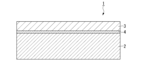
- FIG. 1 is a cross-sectional schematic diagram of a grain-oriented electrical steel sheet obtained by a method for producing a grain-oriented electrical steel sheet according to an embodiment of the present invention.
- FIG. 4 is a flowchart showing a method for manufacturing the grain-oriented electrical steel sheet according to the embodiment.
- FIG. 2 is a diagram for explaining the thermal oxidation-reduction annealing step in the manufacturing method, in which the horizontal axis indicates time and the vertical axis indicates the annealing temperature (base steel sheet temperature).
- Fig. 1 is a cross-sectional schematic diagram of a grain-oriented electrical steel sheet (grain-oriented electrical steel according to the present embodiment) obtained by the manufacturing method of the grain-oriented electrical steel sheet according to the present embodiment.
- the grain-oriented electrical steel sheet 1 according to the present embodiment when viewed on a cut surface whose cutting direction is parallel to the sheet thickness direction, has a base steel sheet 2 and a secondary coating 3 which is an insulating coating (tension-applying insulating coating) disposed on the surface of the base steel sheet 2.
- the average plate thickness of the base steel plate 2 can be, for example, 0.17 mm to 0.29 mm.
- the average film thickness of the secondary coating 3 can be, for example, 1 ⁇ m to 6 ⁇ m.
- the secondary coating 3 is arranged in contact with the base steel sheet 2 (there is no primary coating), thereby ensuring the surface smoothness of the base steel sheet 2.
- the grain-oriented electromagnetic steel sheet 1 according to this embodiment has excellent iron loss characteristics and coating adhesion.
- Fe originates from the base steel components of the base steel sheet 2, and P originates from the secondary coating chemical solution.
- Fe ions diffuse from the base steel side to the coating side, while P ions diffuse and concentrate from the coating side to the base steel side.
- Chemical bonds are formed when Fe ions and P ions meet, resulting in the formation of Fe-P-O compounds.
- Fe-P-O compounds are observed at the interface between the coating and the base steel.
- Figure 2 is a flowchart showing the manufacturing method of the grain-oriented electrical steel sheet according to this embodiment.
- Figure 3 is a diagram explaining the thermal oxidation-reduction annealing process in the same manufacturing method, with the horizontal axis showing time and the vertical axis showing the annealing temperature (base steel sheet temperature).
- the method for producing grain-oriented electrical steel sheet according to the present embodiment includes a hot rolling process in which a slab (steel billet) having a predetermined chemical composition is heated and hot rolled to obtain a hot-rolled steel sheet, a hot-rolled annealing process in which the hot-rolled steel sheet is annealed to obtain a hot-rolled annealed sheet, and then the hot-rolled annealed sheet is immersed in a pickling solution (pickling), a cold rolling process in which the hot-rolled annealed sheet is cold rolled to obtain a cold-rolled steel sheet, a decarburization annealing process in which the cold-rolled steel sheet is decarburized to obtain a decarburization annealed steel sheet, and an annealing process in which the surface of the decarburization annealed steel sheet is subjected to annealing.
- a hot rolling process in which a slab (steel billet) having a predetermined chemical composition is heated and hot rolled to obtain a hot-
- the method mainly includes a separating agent application step of applying a separating agent, a finish annealing step of subjecting the decarburization annealed steel sheet coated with the annealing separating agent to finish annealing to obtain a finish annealed sheet, a surface treatment step of pickling the surface of the finish annealed sheet to obtain a surface-treated steel sheet, a thermal oxidation-reduction annealing step of subjecting the surface-treated steel sheet to two-stage annealing after the surface treatment step to obtain a reduction annealed steel sheet, and a tension-applied insulating coating formation step of forming a tension-applied insulating coating containing phosphate and silica on the surface of the reduction annealed steel sheet after the thermal oxidation-reduction annealing step.
- a nitriding annealing step is included after the decarburization annealing step and before the separating agent application step.
- a pickling step is included after the thermal oxidation-reduction annealing step and before the tension-applied insulating coating formation step.
- the thermal oxidation-reduction annealing process includes a first temperature increasing process, a first annealing process, and a second annealing process
- the tensioned insulating coating forming process includes a second coating chemical application process and a baking process.
- the slab (steel piece) to be subjected to the hot rolling process has, in mass %, the following chemical composition: C: 0.020% to 0.150%, Si: 3.00% to 4.00%, Mn: 0.01% to 0.50%, S: 0.0010% to 0.0400%, Acid-soluble Al: 0.010% to 0.050%, N: 0.002% to 0.020%, Bi:0.0000 ⁇ %0.0200%, P: 0.000% to 0.100%, Sn: 0.00% to 0.50%, Cu: 0.00% to 0.50%, Cr: 0.00% to 0.50%, Sb: 0.00% to 0.20%, Mo: 0.00% to 0.10%, Nb: 0.0000% to 0.0200%, B: 0.0000% to 0.0200%, Te: 0.0000% to 0.0200%, Ni: 0.00% to 0.20%, Se: 0.0000% to 0.0200% with the remainder being Fe and impurities.
- the chemical composition of the above-mentioned slab (steel piece) is as follows, in mass%: Bi: more than 0.0000%, less than 0.0200%, P: more than 0.000%, less than 0.100%, Sn: more than 0.00%, less than 0.50%, Cu: more than 0.00%, less than 0.50%, Cr: more than 0.00%, less than 0.50%, Sb: more than 0.00%, less than 0.20%, Mo: more than 0.00%, less than 0.10%, Nb: more than 0.0000%, less than 0.0200%, B: more than 0.0000%, less than 0.0200%, Te: more than 0.0000%, less than 0.0200%, Ni: more than 0.00%, less than 0.20%, Se: more than 0.0000%, less than 0.0200%, may contain at least one selected from the group consisting of:
- C 0.020% to 0.150%
- C (carbon) is a basic element for steel slabs. C is included to increase the concentration of Goss orientation in secondary recrystallization.
- the C content required to improve the magnetic properties is as follows for a slab: The content is 0.020% or more, preferably 0.040% or more, and more preferably 0.050% or more. However, if excessive C remains in the final product, it can be a factor in iron loss deterioration. Therefore, decarburization annealing is performed. In the process, decarburization is required, but if the C content of the slab exceeds 0.150%, the decarburization becomes difficult.
- the content is preferably 0.120% or less, and more preferably 0.100% or less.
- Si 3.00% to 4.00%
- Si is a basic element for steel slabs. If the Si content is less than 3.00%, the eddy current loss cannot be sufficiently reduced, and good magnetic properties cannot be obtained.
- the Si content is 3.00% or more.
- the Si content is preferably 3.10% or more, and more preferably 3.20% or more.
- the Si content exceeds 4.00%, If the Si content is too high, the steel sheet becomes brittle and the sheet passing property during production is significantly deteriorated, so the Si content is set to 4.00% or less.
- the Si content is preferably 3.80% or less, and more preferably 3.60% or less. % or less.
- Mn 0.01% to 0.50%
- Mn manganese
- MnS manganese
- MnSe when Se is used as part of S
- the Mn content is set to 0.01% or more.
- the Mn content is preferably 0.03% or more.
- the Mn content is set to 0.50% or less, preferably 0.30% or less, and more preferably 0.20% or less.
- S 0.0010% to 0.0400% Se: 0.0000% to 0.0200%
- S is a basic element for steel slabs.
- S is an element that forms MnS, which is an inhibitor.
- the S content of the slab is 0.0010% or more, preferably 0.0100% or more. % or more, more preferably 0.0150% or more.
- the content is 0.0400% or less, preferably 0.0350% or less, and more preferably 0.0300% or less, as a slab. S also can cause magnetic deterioration if it remains in the final product in excess.
- Se selenium
- Se may be used as a part of S (the Se content may be more than 0.0000%).
- the Se content must be 0.0000% or more and 0.0200% or less.
- the Se content is preferably is 0.0000% or more and 0.0150% or less, more preferably 0.0000% or more and 0.0100% or less.
- Acid soluble Al 0.010% to 0.050%
- Acid-soluble Al (aluminum) (sol. Al) is a basic element for steel slabs.
- Acid-soluble Al is an element necessary for forming AlN, which is an inhibitor, and for improving magnetic properties.
- the soluble Al content is 0.010% or more, preferably 0.015% or more, and more preferably 0.020% or more, as a slab. On the other hand, if the slab contains an excessive amount of acid-soluble Al, embrittlement may occur.
- the acid-soluble Al content is 0.050% or less, preferably 0.040% or less, and more preferably 0.030% or less, in terms of the slab. Al needs to be removed (purified) from the base steel sheet during finish annealing.
- N is a basic element for steel slabs.
- N is an element necessary for forming AlN, which is an inhibitor, and for increasing the concentration of Goss orientation during secondary recrystallization. Inhibitor formation
- the N content required for the slab is 0.002% or more, preferably 0.004% or more, and more preferably 0.006% or more. If the N content exceeds 0.020, blisters (voids) are formed in the steel sheet during cold rolling, and the strength of the steel sheet increases, which may deteriorate the sheet passing property during production. %, preferably 0.015% or less, and more preferably 0.010% or less.
- C Like C, if excessive N remains in the final product, it can cause magnetic deterioration. It needs to be purified during annealing.
- P phosphorus
- P is an optional element for steel slabs. If the P content exceeds 0.100%, the workability of the steel sheet may be significantly reduced. Therefore, the P content is set to 0.
- the P content is preferably 0.070% or less, and more preferably 0.030% or less.
- the lower limit of the P content is not particularly limited, and is 0. However, since P has the effect of improving the texture and the magnetic properties of the steel sheet, the P content may be more than 0.000% and may be 0.005% or more. It is also possible to use the following.
- Bi 0.0000% to 0.0200%
- Bi bismuth
- the Bi content is preferably 0.0150% or less, and more preferably 0.020% or less.
- the Bi content is preferably 0.0100% or less.
- the lower limit of the Bi content is not particularly limited and may be 0.0000%. However, since Bi has an effect of improving magnetic properties, The Bi content may be more than 0.0000% and may be 0.0005% or more.
- Sn 0.00% to 0.50%
- Sn (tin) is an optional element for steel slabs. If the Sn content exceeds 0.50%, the secondary recrystallization becomes unstable and may adversely affect the magnetic properties.
- the Sn content may be 0.50% or less.
- the Sn content is preferably 0.40% or less, and more preferably 0.30% or less.
- the lower limit of the Sn content is particularly However, since Sn has the effect of increasing the concentration of Goss orientation and improving magnetic properties, the Sn content may be more than 0.00%. Preferably, it may be 0.01% or more, or 0.03% or more.
- Cu 0.00% to 0.50%
- Cu copper
- the Cu content is preferably 0.40% or less, and more preferably 0.30% or less.
- the lower limit of the Cu content is not particularly limited, and is 0.
- the Cu content may be more than 0.00% and may be less than 0.01%. % or more, or 0.03% or more.
- Cr 0.00% to 0.50% Cr (chromium) is an optional element for steel slabs. If the Cr content exceeds 0.50%, it may form Cr oxides and adversely affect the magnetic properties. Therefore, Cr-containing The Cr content is preferably 0.40% or less, and more preferably 0.30% or less. On the other hand, the lower limit of the Cr content is not particularly limited. However, since Cr has the effect of increasing the concentration of the Goss orientation and improving the magnetic properties, the Cr content may be more than 0.00%. It may be 0.01% or more, or 0.03% or more.
- Sb 0.00% to 0.20%
- Sb antimony
- the Sb content is preferably 0.15% or less, and more preferably 0.10% or less.
- the lower limit of the Sb content is not particularly limited, and is not limited to 0.00%. However, since Sb functions as an inhibitor and has the effect of stabilizing secondary recrystallization, the Sb content may be more than 0.00% and may be 0.01% or more. .
- Mo 0.00% to 0.10%
- Mo molybdenum
- the Mo content is set to 0.10 % or less.
- the Mo content is preferably 0.05% or less, and more preferably 0.03% or less.
- the lower limit of the Mo content is not particularly limited, and is 0.00
- the Mo content may be more than 0.00% and may be 0.01% or more. It is also possible to use the following.
- Nb 0.0000% to 0.0200%
- Nb niobium
- the Nb content is preferably 0.0100% or less, and more preferably 0.0050% or less.
- the lower limit of the Nb content is not particularly limited, and is 0. However, since Nb has the effect of stabilizing secondary recrystallization, the Nb content may be more than 0.0000% and may be 0.0005% or more.
- B 0.0000% to 0.0200%
- B boron
- the B content is preferably 0.0100% or less, and more preferably 0.0050% or less.
- the lower limit of the B content is not particularly limited, and is 0. However, since B has the effect of stabilizing secondary recrystallization, the B content may be more than 0.0000% and may be 0.0005% or more.
- Te 0.0000% to 0.0200% Te (tellurium) is an optional element for steel slabs. If the Te content exceeds 0.0200%, the slab may break during hot rolling or cold rolling. Therefore, the Te content is set to 0.0200 % or less.
- the Te content is preferably 0.0150% or less, and more preferably 0.0100% or less.
- the lower limit of the Te content is not particularly limited, and is 0.0000 However, since Te has the effect of stabilizing secondary recrystallization, the Te content may be more than 0.0000% and may be 0.0005% or more.
- Ni 0.00% to 0.20%
- Ni is an element of choice for steel slabs.
- Ni is an effective element for influencing the crystal orientation rotation that occurs during cold rolling and obtaining a texture favorable for secondary recrystallization.
- Ni is also an effective element for increasing resistivity and reducing iron loss. Therefore, Ni may be contained.
- the Ni content is set to 0.01 % or more is preferable.
- the Ni content exceeds 0.20%, the secondary recrystallization may become unstable. Therefore, if Ni is contained, the Ni content is set to 0.20% or less.
- Ni Content is preferably 0.15% or less, and more preferably 0.10% or less.
- the steel slab to be subjected to the hot rolling process may contain impurities.
- impurities refers to substances that are mixed in from raw materials such as ores and scraps during industrial steel production, or from the production environment, etc.
- the chemical composition of the steel slab to be subjected to the hot rolling process may be measured by a general analytical method. For example, it may be measured using ICP-AES (Inductively Coupled Plasma-Atomic Emission Spectrometry). Acid-soluble Al may be measured by ICP-AES using the filtrate obtained by thermally decomposing a sample with acid.
- C and S may be measured using the combustion-infrared absorption method, and N may be measured using the inert gas fusion-thermal conductivity method.
- the steel slab is first heat-treated.
- the heating temperature may be, for example, 1200°C or higher and 1600°C or lower.
- the lower limit of the heating temperature is preferably 1280°C, and the upper limit of the heating temperature is preferably 1500°C.
- the heated steel slab is then hot-rolled.
- the thickness of the hot-rolled steel sheet after hot rolling is preferably, for example, in the range of 2.0 mm or higher and 3.0 mm or lower.
- Hot-rolled sheet annealing process In the hot-rolled sheet annealing process, the hot-rolled steel sheet obtained in the hot rolling process is annealed. This hot-rolled sheet annealing causes recrystallization in the steel sheet, which ultimately makes it possible to realize good magnetic properties.
- the conditions for the hot-rolled sheet annealing are not particularly limited, but for example, the hot-rolled steel sheet may be annealed in a temperature range of 900°C to 1200°C for 10 seconds to 5 minutes.
- pickling is subsequently performed, in which the surface of the hot-rolled steel sheet after the hot-rolled sheet annealing is pickled by immersing it in a pickling solution to obtain an annealed hot-rolled sheet.
- Cold rolling process In the cold rolling process, the hot-rolled annealed sheet after the hot-rolled sheet annealing process is subjected to one cold rolling or multiple cold rollings with intermediate annealing in between.
- the term "one time” here means that one or multiple passes of cold rolling or intermediate annealing are performed once.
- the heating method of the intermediate annealing is not particularly limited.
- cold rolling may be performed three or more times with intermediate annealing in between, but since this increases the manufacturing cost, it is preferable to perform cold rolling once or twice.
- the final cold rolling reduction in cold rolling may be, for example, in the range of 80% to 95%.
- the thickness of the cold-rolled steel sheet after cold rolling is usually the thickness (final thickness) of the base steel sheet of the grain-oriented electrical steel sheet that is finally manufactured.
- the thickness of the cold-rolled steel sheet after cold rolling is preferably, for example, in the range of 0.17 mm to 0.29 mm.
- decarburization annealing process In the decarburization annealing step, the cold-rolled steel sheet obtained in the cold rolling step is decarburized annealed. This decarburization annealing removes C contained in the cold-rolled steel sheet, causing primary recrystallization.
- the decarburization annealing is preferably performed in a moist atmosphere in order to remove C contained in the cold-rolled steel sheet. For example, annealing may be performed in a moist atmosphere at a temperature range of 700°C to 1000°C for 10 seconds to 10 minutes.
- a nitriding annealing process may be performed after the decarburization annealing process and before the separating agent application process to obtain a nitriding treated steel sheet.
- the decarburization annealed steel sheet after the decarburization annealing is annealed for 10 to 60 seconds in an atmosphere containing a gas having a nitriding ability such as hydrogen, nitrogen, and ammonia at a temperature range of 700°C to 850°C.
- a gas having a nitriding ability such as hydrogen, nitrogen, and ammonia
- an annealing separator is applied to the decarburized annealed steel sheet obtained in the decarburization annealing process and then dried prior to the finish annealing process.
- the annealing separator contains magnesia (MgO), alumina (Al 2 O 3 ), and chloride.
- MgO magnesia
- Al 2 O 3 alumina
- chloride it is preferable that the total content of MgO and Al 2 O 3 is 80.0 mass% or more and 99.5 mass% or less, and the balance is chloride, in terms of solid content.
- the content of chloride in the annealing separator is a value obtained by subtracting the total content of MgO and Al 2 O 3 from 100 mass%, and is preferably 0.5 mass% or more and 20 mass% or less.
- the balance may contain impurities.
- the content of MgO alone is preferably 0.0% by mass or more and 79.5% by mass or less
- the content of Al 2 O 3 alone is preferably 20.0% by mass or more and 99.5% by mass or less.
- the total content of MgO and Al2O3 is more preferably 85.0 mass% or more, and further preferably 90.0 mass% or more.
- the total content of MgO and Al2O3 is more preferably 99.0 mass% or less, and further preferably 95.0 mass% or less.
- the content of the chloride as the balance is more preferably 1.0 mass% or more, and further preferably 5.0 mass% or more.
- the content of the chloride as the balance is more preferably 15.0 mass% or less, and further preferably 10.0 mass% or less.
- examples of the chloride that may be considered include bismuth oxychloride (BiOCl), bismuth trichloride (BiCl 3 ), calcium chloride, iron chloride, cobalt chloride, and nickel chloride.
- the decarburized annealed steel sheet to which the annealing separator has been applied in advance is subjected to final annealing for a long period of time while the steel sheet is wound in a coil shape.
- the annealing conditions for the finish annealing are not particularly limited, and known conditions may be appropriately adopted.
- the decarburized annealed steel sheet that has been coated with an annealing separator and dried may be held in a temperature range of 1000°C to 1300°C for 10 hours to 60 hours.
- the atmosphere during the finish annealing may be, for example, a nitrogen atmosphere or a mixed atmosphere of nitrogen and hydrogen.
- the surface of the finish annealed sheet may be washed with water to remove powder.
- This finish annealing causes secondary recrystallization in the steel sheet, and the crystal orientation is oriented in the ⁇ 110 ⁇ 001> direction.
- the axis of easy magnetization is aligned in the rolling direction, and the crystal grains are coarse.
- This secondary recrystallized structure results in excellent magnetic properties.
- the annealing separator contains chlorides, which suppresses the formation of a primary coating, and the surface of the finish annealed sheet becomes smooth.
- the atmosphere during the finish annealing may be changed to a hydrogen atmosphere to carry out a purification treatment, which purifies the steel sheet by discharging elements such as Al, N, S (including Se when Se is used as part of S) contained in the steel sheet as a steel composition to the outside of the system.
- a purification treatment which purifies the steel sheet by discharging elements such as Al, N, S (including Se when Se is used as part of S) contained in the steel sheet as a steel composition to the outside of the system.
- the surface of the finish annealed sheet obtained in the finish annealing step is pickled to obtain a surface-treated steel sheet.
- the pickling conditions at this time are not particularly specified, but for example, the finish annealed sheet may be immersed in an acid (first treatment liquid) of a specific concentration.
- the first treatment liquid may contain at least one of hydrochloric acid, sulfuric acid, nitric acid, and phosphoric acid, and may have a total acid concentration of 0.1% by volume to 20.0% by volume and a liquid temperature of 50° C. to 90° C.
- the finish annealed sheet may be surface-treated using this first treatment liquid for 3 to 60 seconds.
- the surface of the finish annealed sheet is made active, but it is preferable to perform the surface treatment under conditions that do not create etch pits on the surface of the finish annealed sheet.
- the above conditions can be controlled in a composite and inseparable manner. For example, if the pickling strength is to be increased for any of the above conditions, the other conditions can be changed to weaken the pickling strength, thereby achieving both an active surface state and a smooth surface state.
- Those skilled in the art can perform surface control including the pickling behavior, and it is possible to control the surface state by combining the above conditions, taking into account the effect of each of the above conditions on the pickling strength.
- the total acid concentration of the first treatment liquid is less than 0.1% by volume, it is difficult to make the surface of the finish annealed sheet active, and internal oxide SiO 2 is difficult to form in the next thermal oxidation-reduction annealing process.
- the total acid concentration is 1.0% by volume or more.
- the total acid concentration of the first treatment liquid is more than 20.0% by volume, etch pits are likely to form on the surface of the finish annealed sheet.
- the liquid temperature of the first treatment liquid is less than 50°C, an active surface state cannot be obtained, and if the liquid temperature of the first treatment liquid is more than 90°C, etch pits are likely to form.
- the treatment time of the surface treatment is less than 3 seconds, an active surface state cannot be obtained, and if the treatment time of the surface treatment is more than 60 seconds, etch pits are likely to form.
- the thermal oxidation-reduction annealing process includes a primary temperature-raising process P1, a primary annealing process P2 (first stage), and a secondary annealing process P3 (second stage).
- the thermal oxidation-reduction annealing process of this embodiment is particularly characterized in that the soaking treatment is performed in two stages instead of the conventional one-stage heating.
- ⁇ Primary temperature rise process P1> In the first temperature rise process P1, after the surface treatment step and before the subsequent first annealing process P2, the surface-treated steel sheet is heated from room temperature to a temperature rise temperature T1.
- the temperature rise temperature T1 is specifically selected from within the range of 800°C to 950°C. If the temperature rise temperature T1 is less than 800°C, a SiO 2 oxide film (a film mainly composed of SiO 2 ) is unlikely to be formed. Therefore, the temperature rise temperature T1 is set to 800°C or higher.
- the temperature rise temperature T1 is preferably 820°C or higher, more preferably 840°C or higher.
- the temperature rise temperature T1 is set to 950°C or lower.
- the temperature rise temperature T1 is preferably 920°C or lower, more preferably 900°C or lower.
- the atmospheric dew point at a steel sheet temperature of 100° C. to 800° C. it is preferable to control the atmospheric dew point at a steel sheet temperature of 100° C. to 800° C. to be equal to or lower than 0° C.
- the oxygen potential PH 2 O/PH 2 defined by the ratio of the water vapor partial pressure PH 2 O to the hydrogen partial pressure PH 2 in the atmosphere is equal to or lower than 0.5000. If the oxygen potential PH 2 O/PH 2 exceeds 0.5000, it becomes difficult to form a SiO 2 oxide film. Therefore, it is preferable to set the oxygen potential PH 2 O/PH 2 to 0.5000 or less.
- the oxygen potential PH 2 O/PH 2 is more preferably 0.4000 or less, and even more preferably 0.3000 or less. From the viewpoint of ensuring a uniform SiO 2 oxide film, it is preferable to set the oxygen potential PH 2 O/PH 2 to 0.0001 or more. It is more preferably 0.0010 or more, and even more preferably 0.0050 or more.
- the average heating rate when the steel sheet temperature is 550° C. to 800° C. within the range of 100° C./sec to 2000° C./sec. If the average heating rate is below 100°C/sec, there is a concern that oxide films other than SiO2 , such as Fe2SiO4 , may be generated.
- the average heating rate is more preferably 150°C/sec or more, and even more preferably 200°C/sec or more. Conversely, if the average heating rate exceeds 2000°C/sec, the generation of SiO2 itself is reduced, and it is difficult to obtain the coating adhesion improvement effect. Therefore, the average heating rate is preferably 2000°C/sec.
- the average heating rate is more preferably 1800°C/sec or less, and even more preferably 1600°C/sec or less.
- a homogeneous SiO 2 oxide film is preferably formed on the surface of the steel sheet. That is, the SiO 2 oxide film is formed by the reaction of Si in the steel sheet surface with O 2 in the atmosphere, but by performing the above control, a SiO 2 oxide film with a uniform thickness can be formed evenly over the entire surface of the steel sheet surface.
- the uniform SiO 2 oxide film has the effect of stabilizing the oxidation behavior of the steel sheet in the subsequent primary annealing process P2, and contributes to improving the coating adhesion.
- the start of control of the steel sheet average heating rate may be set to a relatively low temperature range of about 100°C.
- the average heating rate from 550°C to 800°C is set to 100°C/sec to 2000°C/sec. This allows sufficient internal oxide SiO2 to be formed on the surface of the base steel sheet without requiring special equipment.
- the first annealing process P2 is performed following the first heating process P1.
- the steel sheet temperature is held at the annealing temperature T2 for a constant holding time in the range of 10 to 200 seconds in an atmosphere with a constant oxygen potential PH 2 O/PH 2 in the range of 0.10 to 10.00.
- the annealing temperature T2 is a constant temperature in the range of 800°C to 900°C. If the oxygen potential PH 2 O/PH 2 is less than 0.10, Fe 2 SiO 4 may not precipitate. Fe 2 SiO 4 is reduced to pure iron, which is useful for coating adhesion, by the subsequent secondary annealing process P3.
- the lower limit of the oxygen potential PH 2 O/PH 2 is set to 0.10.
- the lower limit of the oxygen potential PH 2 O/PH 2 is preferably 0.15, and more preferably 0.20.
- the upper limit of the oxygen potential PH2O / PH2 is set to 10.00.
- the oxygen potential PH2O / PH2 is preferably 1.00 or less, and more preferably 0.60 or less.
- the annealing temperature T2 is set to 800° C. or higher. Conversely, if the annealing temperature T2 exceeds 900° C., Fe 2 SiO 4 is excessively generated, which may lead to deterioration of the coating adhesion. Therefore, the annealing temperature T2 is set to 900° C. or less.
- the annealing temperature T2 is more preferably 880° C. or less, and further preferably 850° C. or less.
- the holding time is set to 10 seconds or more.
- the holding time is preferably 30 seconds or more, and more preferably 50 seconds or more.
- the holding time is set to 200 seconds or less.
- the holding time is preferably 180 seconds or less, and more preferably 150 seconds or less.
- ⁇ Secondary annealing process P3> the steel sheet is held at an annealing temperature T3 for a constant holding time in the range of 3 seconds to 100 seconds in an atmosphere with a constant oxygen potential PH 2 O/PH 2 less than 0.1000 and a constant dew point less than ⁇ 20° C.
- the annealing temperature T3 is a constant temperature in the range of 900° C. to 1100° C. If the oxygen potential PH2O / PH2 is 0.1000 or more, Fe2SiO4 cannot be sufficiently reduced, and the coating adhesion may deteriorate. Therefore, the oxygen potential PH2O / PH2 is set to less than 0.1000.
- the oxygen potential PH2O / PH2 is preferably 0.0800 or less, and more preferably 0.0600 or less.
- the dew point is controlled to less than ⁇ 20° C. If the dew point is ⁇ 20° C. or higher, iron-based oxides such as FeO are generated, which adversely affect the coating adhesion.
- the annealing temperature T3 is set to 900° C. or higher.
- the annealing temperature T3 is preferably 920° C. or higher, and more preferably 940° C. or higher.
- the annealing temperature T3 is set to 1100° C. or less.
- the annealing temperature T3 is preferably 1000° C. or less, and more preferably 980° C. or less.
- the holding time is set to 3 seconds or more.
- the holding time is preferably 10 seconds or more, and more preferably 20 seconds or more.
- the holding time is set to 100 seconds or less.
- the holding time is preferably 80 seconds or less, and more preferably 60 seconds or less.
- the transition from the primary annealing process P2 to the secondary annealing process P3 may be performed successively with another primary heating process in between as shown in FIG. 3. That is, after the primary annealing process P2 is completed, the steel sheet temperature may be subsequently raised from the annealing temperature T2, and the secondary annealing process P3 may then be started at the annealing temperature T3. Alternatively, after the primary annealing process P2 is completed, the steel sheet temperature may be temporarily lowered from the annealing temperature T2 and returned to room temperature, and then the steel sheet may be reheated and the secondary annealing process P3 may be started at the annealing temperature T3.
- a pickling step may be performed after the thermal oxidation-reduction annealing step and before the subsequent tension-applying insulating coating forming step.
- the reduction-annealed steel sheet obtained in the thermal oxidation-reduction annealing step is immersed for 3 to 60 seconds in an acid (second treatment liquid) containing at least one of hydrochloric acid, sulfuric acid, nitric acid, and phosphoric acid, having a total acid concentration of 0.1% by volume to 20.0% by volume, and having a liquid temperature of 50° C. to 90° C. If the total acid concentration of the second treatment liquid is less than 0.1% by volume, an active surface state cannot be obtained.
- the acid concentration of the second treatment liquid is set to 0.1% by volume to 20.0% by volume.
- the treatment time of the surface treatment is less than 3 seconds, an active surface state cannot be obtained, and if the treatment time of the surface treatment is more than 60 seconds, the surface may become uneven, and the magnetic properties may deteriorate.
- the pickling step may be omitted, in which case the tensioned insulating coating step is carried out following the thermal oxidation-reduction annealing step.
- the tensioned insulating coating formation process is carried out following the thermal oxidation-reduction annealing process or the pickling process.
- a secondary coating (tensioned insulating coating) 3 is formed on the surface of the reduction-annealed steel sheet obtained in the thermal oxidation-reduction annealing process or on the surface of the pickled sheet obtained in the pickling process.
- the secondary coating 3 is a coating containing phosphate and silica, and the specific components and their contents may be within known conditions.
- the tensioned insulating coating forming process includes a secondary coating solution application process and a baking process. In the following description, the reduction annealed steel sheet and the pickled steel sheet are collectively referred to as "steel sheet”.
- an insulating coating solution containing at least one of aluminum phosphate and silica as a main component (hereinafter also referred to as "secondary coating solution") is applied to the surface of the steel sheet. It is preferable that the secondary coating solution does not contain chromium. Other than aluminum phosphate, phosphates such as Ca, Al, Sr, etc. may be used. Silica is not particularly limited to silica with a specific property.
- the particle size is also not particularly limited to a specific particle size, but is preferably 200 nm (number average particle size) or less. For example, 5 nm to 30 nm is sufficient. If the particle size exceeds 200 nm, it may settle in the coating liquid.
- the steel sheet to which the secondary coating solution has been applied is subjected to a heat treatment to form an insulating coating (secondary coating 3) on the surface of the steel sheet.
- This insulating coating applies tension to the steel sheet, thereby reducing the iron loss of the steel sheet as a single sheet, and also ensures electrical insulation between the steel sheets when grain-oriented electrical steel sheets are stacked for use, thereby reducing the iron loss of the iron core.
- the heating conditions of the heat treatment may be, for example, a constant temperature in the range of 350° C. to 1150° C. for a constant time in the range of 5 to 300 seconds.
- the oxygen potential PH 2 O/PH 2 of the atmosphere may be controlled as necessary.
- the thermal oxidation-reduction annealing process is a two-stage heating process consisting of a primary annealing step P2 and a secondary annealing step P3, so that ⁇ -Fe is uniformly precipitated on the steel sheet surface in advance.
- this ⁇ -Fe dissolves into the secondary coating solution, and Fe atoms diffuse into the secondary coating solution.
- Fe dissolves in phosphate, and an Fe-P-O compound is formed at the interface between the base steel sheet 2 and the secondary coating 3. Because this Fe-P-O compound is present at the interface, the grain-oriented electrical steel sheet 1 according to this embodiment has high coating adhesion and excellent iron loss characteristics.
- the grain-oriented electrical steel sheet 1 shown in FIG. 1 is manufactured.
- the steel sheet after the secondary coating 3 is formed may be subjected to flattening annealing for shape correction, if necessary. By performing this flattening annealing, it becomes possible to further reduce the iron loss of the grain-oriented electrical steel sheet 1.
- a magnetic domain control treatment may be performed before or after the tensioned insulating coating forming step, as necessary. By performing the magnetic domain control treatment, the iron loss of the grain-oriented electrical steel sheet can be further reduced.
- linear or dot-like grooves extending in a direction intersecting the rolling direction may be formed at predetermined intervals along the rolling direction.
- linear or dot-like stress distortion portions extending in a direction intersecting the rolling direction may be formed at predetermined intervals along the rolling direction.
- the magnetic domain control treatment narrows the width of the 180° magnetic domains (divides the 180° magnetic domains).
- a mechanical groove forming method using gears or the like a chemical groove forming method using electrolytic etching, a thermal groove forming method using laser irradiation, etc. can be applied.
- laser beam irradiation, electron beam irradiation, etc. can be applied.
- the manufacturing method for grain-oriented electrical steel sheet described above makes it possible to manufacture grain-oriented electrical steel sheet with higher coating adhesion without compromising magnetic properties.
- the chemical composition of all slabs No. a to j is as follows, in mass%: C: 0.020% to 0.150%, Si: 3.00% to 4.00%, Mn: 0.01% to 0.50%, S: 0.0010% to 0.0400%, Acid-soluble Al: 0.010% to 0.050%, N: 0.002% to 0.020%, and the balance being Fe and impurities.
- C 0.020% to 0.150%
- Si 3.00% to 4.00%
- Mn 0.01% to 0.50%
- S 0.0010% to 0.0400%
- Acid-soluble Al 0.010% to 0.050%
- N 0.002% to 0.020%
- the balance being Fe and impurities.
- the chemical composition is, in mass%, Bi: 0.0200% or less, P: 0.100% or less, Sn: 0.50% or less, Cu: 0.50% or less, Cr: 0.50% or less, Sb: 0.20% or less, Mo: 0.10% or less, Nb: 0.0200% or less, B: 0.0200% or less, Te: 0.0200% or less, Ni: 0.20% or less, Se: 0.0200% or less, At least one selected from the group consisting of: Then, each of these slabs a to j was heated to a constant temperature within the range of 1100° C. to 1400° C. and subjected to hot rolling to produce a hot-rolled steel sheet having a thickness of 2.3 mm.
- the hot-rolled steel sheet obtained in the hot rolling process was subjected to hot-rolled sheet annealing at 1100° C. for 100 seconds, and the surface was further pickled by immersing it in a pickling solution. In this way, a hot-rolled sheet annealed sheet was obtained.
- the hot-rolled and annealed sheets after pickling were subjected to one cold rolling or multiple cold rolling with intermediate annealing in between to obtain cold-rolled steel sheets having a base steel sheet thickness of 0.22 mm to 0.23 mm as shown in Table 2A below.
- the cold-rolled steel sheet obtained in the cold rolling step was subjected to decarburization annealing at 820° C. for 140 seconds in a mixed gas of nitrogen and hydrogen to obtain a decarburization annealed steel sheet.
- the mixed gas of nitrogen and hydrogen was a humidified atmosphere.
- a nitriding treatment step was performed after the decarburization annealing step. That is, for Test Nos. 1, 2, 9, 10, 18, 19, and 20, a nitriding treatment was performed after the decarburization annealing step.
- a slurry of an annealing separator mainly composed of MgO and alumina was applied to the surface of the decarburization annealed steel sheet after the decarburization annealing step or the nitriding annealed steel sheet after the nitriding annealing step.
- the composition of the annealing separator used is as shown in Table 2B.
- the decarburized annealed steel sheet coated with the annealing separator was subjected to final annealing for about 20 hours at 1200° C.
- the annealing atmosphere in the temperature increasing step of the final annealing step was a mixed gas of nitrogen and hydrogen, and the annealing atmosphere in the 1200° C. soaking step was hydrogen gas.
- the finish annealed steel sheet obtained in the finish annealing step was surface-treated by immersing it in a treatment solution containing sulfuric acid and having a concentration (acid concentration) and temperature shown in Table 2C for a time also shown in Table 2C to obtain a surface-treated steel sheet.
- thermal oxidation-reduction annealing process a heat treatment was performed to subject the surface-treated steel sheet after the surface treatment process to intermediate annealing.
- This thermal oxidation-reduction annealing process included a first temperature-raising process P1, a first annealing process P2, and a second annealing process P3.
- the surface-treated steel sheet was heated after the surface treatment step and before the subsequent first annealing process P2.
- the temperature-raising rate in the range of 550°C to 800°C and the oxygen potential PH 2 O/PH 2 were set as shown in Table 2A.
- the first annealing process P2 was performed following the first heating process P1.
- the annealing temperature T2 the annealing time (holding time), and the oxygen potential PH 2 O/PH 2 were as shown in Table 2A. Furthermore, after the first annealing process P2, the heating temperature was increased to perform the second annealing process P3. Specifically, in this second annealing process P3, the annealing temperature T3, the annealing time (holding time), and the oxygen potential PH2O / PH2 were set as shown in Table 2B.
- Test Nos. 6 to 8 were subjected to a pickling process in which they were pickled for 10 seconds in a 1% sulfuric acid solution at 60°C.
- the other Test Nos. 1 to 5 and 9 to 30 were not subjected to the pickling process after the thermal oxidation-reduction annealing process.
- a tensioned insulating coating formation process was carried out. That is, in this tensioned insulating coating formation process, a secondary coating (tensioned insulating coating) containing aluminum phosphate and silica was formed on the surface of the reduction-annealed steel sheet obtained in the thermal oxidation-reduction annealing process or the surface of the pickled sheet obtained in the pickling process.
- the tensioned insulating coating formation process includes a secondary coating solution application process and a baking process.
- the reduction-annealed steel sheet and the pickled sheet are collectively referred to as "steel sheet".
- an insulating coating forming solution containing aluminum phosphate and silica (hereinafter also referred to as "secondary coating solution”) was applied to the surface of the steel sheet.
- second coating solution an insulating coating forming solution containing aluminum phosphate and silica
- the heating conditions for the heat treatment at this time were to hold the steel sheet at 900°C for a certain period of time within a range of 10 to 20 seconds.
- the annealing atmosphere was a humidified atmosphere containing a mixture of nitrogen and hydrogen gas with a dew point controlled to 20°C or higher.
- the coating adhesion was evaluated by the coating remaining area ratio when the test piece was wrapped around a cylinder with a diameter of 20 mm and bent 180°.
- the area ratio of the coating remaining surface to the steel sheet area in contact with the cylinder was calculated.
- the steel sheet area in contact with the roll was calculated.
- the remaining surface area was calculated by taking a photograph of the steel sheet after the test and performing image analysis on the photographic image.
- the iron loss W17/50 W/kg
- the iron loss W17/50 W/kg
- the iron loss W17/50 was measured under conditions of AC frequency: 50 Hz and excitation magnetic flux density: 1.7 T.
- a test piece was deemed to have passed if its iron loss W17/50 was less than 0.75 W/kg.
- the magnetic flux density was measured by applying a magnetic field of 800 A/m to the test pieces, and the magnetic flux density B8 (T) in the rolling direction was measured. The results are shown in Table 2C.
- the steel sheet temperature was held at a constant temperature in the range of 800°C to 900°C for a constant holding time in the range of 10 seconds to 200 seconds in an atmosphere with a constant oxygen potential PH 2 O/PH 2 in the range of 0.10 to 10.00 in the primary annealing process P2.
- the steel sheet temperature was held at a constant temperature in the range of 900°C to 1100° C for a constant holding time in the range of 3 seconds to 100 seconds in an atmosphere with a constant oxygen potential PH 2 O/PH 2 less than 0.1000 in the secondary annealing process P3.
- the annealing temperature T2 was 780° C., which was below the lower limit of 800° C. As a result, the coating adhesion was insufficient.
- the annealing temperature T2 was 920° C., which exceeded the upper limit of 900° C. As a result, the coating adhesion was insufficient.
- the annealing time was 8 seconds, which was below the lower limit of 10 seconds, resulting in insufficient coating adhesion.
- Steel No. 12 the annealing temperature T2 was 780° C., which was below the lower limit of 800° C. As a result, the coating adhesion was insufficient.
- the annealing temperature T2 was 920° C., which exceeded the upper limit of 900° C. As a result, the coating adhesion was insufficient.
- the annealing time was 8 seconds, which was below the lower limit of 10 seconds, resulting in insufficient coating adhesion.
- the annealing time was 210 seconds, which exceeded the upper limit of 200 seconds, resulting in insufficient coating adhesion.
- the oxygen potential in the first annealing step P2 was 0.09, which was below the lower limit of 0.10. As a result, the coating adhesion was insufficient.
- the oxygen potential in the first annealing process P2 was 10.52, which exceeded the upper limit of 10.00.
- the surface treatment process was not performed. As a result, the coating adhesion was insufficient.
- the annealing temperature T3 in the secondary annealing process P3 was 880° C., which was below the lower limit of 900° C. In addition, the surface treatment process was not performed. As a result, the coating adhesion was insufficient. In addition, in Steel No. 19, the annealing temperature T3 in the secondary annealing process P3 was 1110° C., which exceeded the upper limit of 1100° C. As a result, the coating adhesion was insufficient. In addition, in steel No. 20, the annealing time in the secondary annealing process P3 was 2 seconds, which was below the lower limit of 3 seconds. As a result, the coating adhesion was insufficient. In addition, in steel No.
- the annealing time in the secondary annealing process P3 was 110 seconds, which exceeded the upper limit of 100 seconds. As a result, the coating adhesion was insufficient.
- the oxygen potential in the secondary annealing process P3 was 0.1255, which exceeded the upper limit of 0.1000. As a result, the coating adhesion was insufficient.
- the dew point in the secondary annealing process P3 was ⁇ 20° C. or higher, exceeding the upper limit of less than ⁇ 20° C. As a result, the coating adhesion was insufficient.
- no surface treatment step was performed, which resulted in poor coating adhesion. In the case of Steel No.
- the oxygen potential in the first annealing step P2 was 10.52, which exceeded the upper limit of 10.00, resulting in insufficient coating adhesion.
- the annealing temperature T3 in the secondary annealing process P3 was 880° C., which was below the lower limit of 900° C. As a result, the coating adhesion was insufficient.
- the steel sheet temperature in order to meet the pass criteria for both coating adhesion and iron loss, in the first annealing process P2, the steel sheet temperature must be held at a constant temperature in the range of 800°C to 900°C for a constant holding time in the range of 10 to 200 seconds in an atmosphere where the oxygen potential PH 2 O /PH 2 is a constant value in the range of 0.10 to 10.00, and in addition, in the second annealing process P3, the steel sheet temperature must be held at a constant temperature in the range of 900°C to 1100°C for a constant holding time in the range of 3 to 100 seconds in an atmosphere where the oxygen potential PH 2 O/PH 2 is a constant value less than 0.1000.
- the present invention makes it possible to produce grain-oriented electrical steel sheets with higher coating adhesion without compromising magnetic properties. This makes the product highly applicable in industry.
Landscapes
- Chemical & Material Sciences (AREA)
- Engineering & Computer Science (AREA)
- Mechanical Engineering (AREA)
- Organic Chemistry (AREA)
- Metallurgy (AREA)
- Materials Engineering (AREA)
- Physics & Mathematics (AREA)
- Thermal Sciences (AREA)
- Crystallography & Structural Chemistry (AREA)
- Electromagnetism (AREA)
- Manufacturing & Machinery (AREA)
- Dispersion Chemistry (AREA)
- Power Engineering (AREA)
- General Chemical & Material Sciences (AREA)
- Chemical Kinetics & Catalysis (AREA)
- Manufacturing Of Steel Electrode Plates (AREA)
Priority Applications (4)
| Application Number | Priority Date | Filing Date | Title |
|---|---|---|---|
| KR1020257021253A KR20250114378A (ko) | 2023-02-01 | 2024-02-01 | 방향성 전자 강판의 제조 방법 |
| CN202480006238.7A CN120435575A (zh) | 2023-02-01 | 2024-02-01 | 方向性电磁钢板的制造方法 |
| EP24750391.5A EP4660330A1 (en) | 2023-02-01 | 2024-02-01 | Method for producing grain-oriented electrical steel sheet |
| JP2024575003A JPWO2024162442A1 (https=) | 2023-02-01 | 2024-02-01 |
Applications Claiming Priority (2)
| Application Number | Priority Date | Filing Date | Title |
|---|---|---|---|
| JP2023-013751 | 2023-02-01 | ||
| JP2023013751 | 2023-02-01 |
Publications (1)
| Publication Number | Publication Date |
|---|---|
| WO2024162442A1 true WO2024162442A1 (ja) | 2024-08-08 |
Family
ID=92146887
Family Applications (1)
| Application Number | Title | Priority Date | Filing Date |
|---|---|---|---|
| PCT/JP2024/003324 Ceased WO2024162442A1 (ja) | 2023-02-01 | 2024-02-01 | 方向性電磁鋼板の製造方法 |
Country Status (5)
| Country | Link |
|---|---|
| EP (1) | EP4660330A1 (https=) |
| JP (1) | JPWO2024162442A1 (https=) |
| KR (1) | KR20250114378A (https=) |
| CN (1) | CN120435575A (https=) |
| WO (1) | WO2024162442A1 (https=) |
Citations (9)
| Publication number | Priority date | Publication date | Assignee | Title |
|---|---|---|---|---|
| JPH08269560A (ja) | 1995-03-31 | 1996-10-15 | Nippon Steel Corp | グラス被膜を有しない鉄損の優れた一方向性電磁鋼板の製造方法 |
| WO2019182149A1 (ja) | 2018-03-22 | 2019-09-26 | 日本製鉄株式会社 | 方向性電磁鋼板及び方向性電磁鋼板の製造方法 |
| WO2020149345A1 (ja) | 2019-01-16 | 2020-07-23 | 日本製鉄株式会社 | 方向性電磁鋼板及びその製造方法 |
| JP2020111809A (ja) * | 2019-01-16 | 2020-07-27 | 日本製鉄株式会社 | 方向性電磁鋼板 |
| JP2020111813A (ja) * | 2019-01-16 | 2020-07-27 | 日本製鉄株式会社 | 方向性電磁鋼板 |
| WO2020162611A1 (ja) * | 2019-02-08 | 2020-08-13 | 日本製鉄株式会社 | 方向性電磁鋼板、方向性電磁鋼板の絶縁被膜形成方法、及び方向性電磁鋼板の製造方法 |
| CN114686766A (zh) * | 2022-03-31 | 2022-07-01 | 武汉钢铁有限公司 | 一种可耐800℃去应力退火的无硅酸镁底涂层取向硅钢及生产方法 |
| JP2023013751A (ja) | 2021-07-16 | 2023-01-26 | 帝人株式会社 | 非水系二次電池用セパレータ及び非水系二次電池 |
| WO2023204269A1 (ja) * | 2022-04-21 | 2023-10-26 | 日本製鉄株式会社 | 方向性電磁鋼板およびその製造方法 |
Family Cites Families (1)
| Publication number | Priority date | Publication date | Assignee | Title |
|---|---|---|---|---|
| JP2008269560A (ja) | 2007-03-23 | 2008-11-06 | Seiko Epson Corp | シーン識別装置、及び、シーン識別方法 |
-
2024
- 2024-02-01 WO PCT/JP2024/003324 patent/WO2024162442A1/ja not_active Ceased
- 2024-02-01 JP JP2024575003A patent/JPWO2024162442A1/ja active Pending
- 2024-02-01 KR KR1020257021253A patent/KR20250114378A/ko active Pending
- 2024-02-01 EP EP24750391.5A patent/EP4660330A1/en active Pending
- 2024-02-01 CN CN202480006238.7A patent/CN120435575A/zh active Pending
Patent Citations (9)
| Publication number | Priority date | Publication date | Assignee | Title |
|---|---|---|---|---|
| JPH08269560A (ja) | 1995-03-31 | 1996-10-15 | Nippon Steel Corp | グラス被膜を有しない鉄損の優れた一方向性電磁鋼板の製造方法 |
| WO2019182149A1 (ja) | 2018-03-22 | 2019-09-26 | 日本製鉄株式会社 | 方向性電磁鋼板及び方向性電磁鋼板の製造方法 |
| WO2020149345A1 (ja) | 2019-01-16 | 2020-07-23 | 日本製鉄株式会社 | 方向性電磁鋼板及びその製造方法 |
| JP2020111809A (ja) * | 2019-01-16 | 2020-07-27 | 日本製鉄株式会社 | 方向性電磁鋼板 |
| JP2020111813A (ja) * | 2019-01-16 | 2020-07-27 | 日本製鉄株式会社 | 方向性電磁鋼板 |
| WO2020162611A1 (ja) * | 2019-02-08 | 2020-08-13 | 日本製鉄株式会社 | 方向性電磁鋼板、方向性電磁鋼板の絶縁被膜形成方法、及び方向性電磁鋼板の製造方法 |
| JP2023013751A (ja) | 2021-07-16 | 2023-01-26 | 帝人株式会社 | 非水系二次電池用セパレータ及び非水系二次電池 |
| CN114686766A (zh) * | 2022-03-31 | 2022-07-01 | 武汉钢铁有限公司 | 一种可耐800℃去应力退火的无硅酸镁底涂层取向硅钢及生产方法 |
| WO2023204269A1 (ja) * | 2022-04-21 | 2023-10-26 | 日本製鉄株式会社 | 方向性電磁鋼板およびその製造方法 |
Non-Patent Citations (1)
| Title |
|---|
| See also references of EP4660330A1 |
Also Published As
| Publication number | Publication date |
|---|---|
| JPWO2024162442A1 (https=) | 2024-08-08 |
| EP4660330A1 (en) | 2025-12-10 |
| KR20250114378A (ko) | 2025-07-29 |
| CN120435575A (zh) | 2025-08-05 |
Similar Documents
| Publication | Publication Date | Title |
|---|---|---|
| EP1108794B1 (en) | Electrical steel sheet suitable for compact iron core and manufacturing method therefor | |
| JP6915689B2 (ja) | 方向性電磁鋼板及びその製造方法 | |
| JP5692479B2 (ja) | 方向性電磁鋼板の製造方法 | |
| KR101949626B1 (ko) | 방향성 전기 강판의 제조 방법 및 방향성 전기 강판 제조용의 1 차 재결정 강판 | |
| JP7312249B2 (ja) | 二方向性電磁鋼板およびその製造方法 | |
| JP7299511B2 (ja) | 方向性電磁鋼板の製造方法 | |
| JP7230930B2 (ja) | 方向性電磁鋼板の製造方法 | |
| JP6436316B2 (ja) | 方向性電磁鋼板の製造方法 | |
| JP5068579B2 (ja) | 高磁束密度方向性電磁鋼板の製造方法 | |
| JP7214974B2 (ja) | 方向性電磁鋼板の製造方法 | |
| KR20180074382A (ko) | 방향성 전기강판 및 이의 제조방법 | |
| JP3312000B2 (ja) | 被膜特性および磁気特性に優れる方向性けい素鋼板の製造方法 | |
| JP7568948B2 (ja) | 電磁鋼板の製造方法 | |
| JP7804241B2 (ja) | 方向性電磁鋼板の製造方法 | |
| JP7299512B2 (ja) | 方向性電磁鋼板の製造方法 | |
| WO2024162442A1 (ja) | 方向性電磁鋼板の製造方法 | |
| JP3885428B2 (ja) | 方向性電磁鋼板の製造方法 | |
| JP7486436B2 (ja) | 一方向性電磁鋼板の製造方法 | |
| JP7315857B2 (ja) | 方向性電磁鋼板の製造方法 | |
| JP2560579B2 (ja) | 高透磁率を有する高珪素鋼板の製造方法 | |
| JP5928362B2 (ja) | 方向性電磁鋼板の製造方法および方向性電磁鋼板製造用の一次再結晶鋼板 | |
| JPH1136018A (ja) | グラス皮膜と磁気特性の極めて優れる方向性電磁鋼板の製造方法 | |
| JPH11241120A (ja) | 均質なフォルステライト質被膜を有する方向性けい素鋼板の製造方法 | |
| JP7816664B1 (ja) | 方向性電磁鋼板の製造方法 | |
| JP7816665B1 (ja) | 方向性電磁鋼板の製造方法 |
Legal Events
| Date | Code | Title | Description |
|---|---|---|---|
| 121 | Ep: the epo has been informed by wipo that ep was designated in this application |
Ref document number: 24750391 Country of ref document: EP Kind code of ref document: A1 |
|
| WWE | Wipo information: entry into national phase |
Ref document number: 2024575003 Country of ref document: JP |
|
| WWE | Wipo information: entry into national phase |
Ref document number: 1020257021253 Country of ref document: KR |
|
| WWE | Wipo information: entry into national phase |
Ref document number: 202480006238.7 Country of ref document: CN |
|
| WWE | Wipo information: entry into national phase |
Ref document number: 202517063141 Country of ref document: IN |
|
| REG | Reference to national code |
Ref country code: BR Ref legal event code: B01A Ref document number: 112025013962 Country of ref document: BR |
|
| WWP | Wipo information: published in national office |
Ref document number: 1020257021253 Country of ref document: KR |
|
| WWP | Wipo information: published in national office |
Ref document number: 202480006238.7 Country of ref document: CN |
|
| WWP | Wipo information: published in national office |
Ref document number: 202517063141 Country of ref document: IN |
|
| WWE | Wipo information: entry into national phase |
Ref document number: 2025120847 Country of ref document: RU |
|
| NENP | Non-entry into the national phase |
Ref country code: DE |
|
| WWP | Wipo information: published in national office |
Ref document number: 2025120847 Country of ref document: RU |
|
| WWP | Wipo information: published in national office |
Ref document number: 2024750391 Country of ref document: EP |
|
| ENP | Entry into the national phase |
Ref document number: 112025013962 Country of ref document: BR Kind code of ref document: A2 Effective date: 20250704 |