WO2024162313A1 - 繊維製品、機能性糸、およびセンシング方法 - Google Patents
繊維製品、機能性糸、およびセンシング方法 Download PDFInfo
- Publication number
- WO2024162313A1 WO2024162313A1 PCT/JP2024/002783 JP2024002783W WO2024162313A1 WO 2024162313 A1 WO2024162313 A1 WO 2024162313A1 JP 2024002783 W JP2024002783 W JP 2024002783W WO 2024162313 A1 WO2024162313 A1 WO 2024162313A1
- Authority
- WO
- WIPO (PCT)
- Prior art keywords
- light
- yarn
- information
- textile product
- product according
- Prior art date
- Legal status (The legal status is an assumption and is not a legal conclusion. Google has not performed a legal analysis and makes no representation as to the accuracy of the status listed.)
- Ceased
Links
Images


Classifications
-
- D—TEXTILES; PAPER
- D02—YARNS; MECHANICAL FINISHING OF YARNS OR ROPES; WARPING OR BEAMING
- D02G—CRIMPING OR CURLING FIBRES, FILAMENTS, THREADS, OR YARNS; YARNS OR THREADS
- D02G3/00—Yarns or threads, e.g. fancy yarns; Processes or apparatus for the production thereof, not otherwise provided for
- D02G3/44—Yarns or threads characterised by the purpose for which they are designed
-
- A—HUMAN NECESSITIES
- A41—WEARING APPAREL
- A41D—OUTERWEAR; PROTECTIVE GARMENTS; ACCESSORIES
- A41D31/00—Materials specially adapted for outerwear
-
- A—HUMAN NECESSITIES
- A41—WEARING APPAREL
- A41D—OUTERWEAR; PROTECTIVE GARMENTS; ACCESSORIES
- A41D31/00—Materials specially adapted for outerwear
- A41D31/04—Materials specially adapted for outerwear characterised by special function or use
-
- D—TEXTILES; PAPER
- D01—NATURAL OR MAN-MADE THREADS OR FIBRES; SPINNING
- D01F—CHEMICAL FEATURES IN THE MANUFACTURE OF ARTIFICIAL FILAMENTS, THREADS, FIBRES, BRISTLES OR RIBBONS; APPARATUS SPECIALLY ADAPTED FOR THE MANUFACTURE OF CARBON FILAMENTS
- D01F1/00—General methods for the manufacture of artificial filaments or the like
- D01F1/02—Addition of substances to the spinning solution or to the melt
- D01F1/06—Dyes
-
- D—TEXTILES; PAPER
- D01—NATURAL OR MAN-MADE THREADS OR FIBRES; SPINNING
- D01F—CHEMICAL FEATURES IN THE MANUFACTURE OF ARTIFICIAL FILAMENTS, THREADS, FIBRES, BRISTLES OR RIBBONS; APPARATUS SPECIALLY ADAPTED FOR THE MANUFACTURE OF CARBON FILAMENTS
- D01F6/00—Monocomponent artificial filaments or the like of synthetic polymers; Manufacture thereof
- D01F6/88—Monocomponent artificial filaments or the like of synthetic polymers; Manufacture thereof from mixtures of polycondensation products as major constituent with other polymers or low-molecular-weight compounds
- D01F6/92—Monocomponent artificial filaments or the like of synthetic polymers; Manufacture thereof from mixtures of polycondensation products as major constituent with other polymers or low-molecular-weight compounds of polyesters
-
- D—TEXTILES; PAPER
- D02—YARNS; MECHANICAL FINISHING OF YARNS OR ROPES; WARPING OR BEAMING
- D02G—CRIMPING OR CURLING FIBRES, FILAMENTS, THREADS, OR YARNS; YARNS OR THREADS
- D02G3/00—Yarns or threads, e.g. fancy yarns; Processes or apparatus for the production thereof, not otherwise provided for
- D02G3/02—Yarns or threads characterised by the material or by the materials from which they are made
- D02G3/04—Blended or other yarns or threads containing components made from different materials
- D02G3/045—Blended or other yarns or threads containing components made from different materials all components being made from artificial or synthetic material
-
- D—TEXTILES; PAPER
- D03—WEAVING
- D03D—WOVEN FABRICS; METHODS OF WEAVING; LOOMS
- D03D15/00—Woven fabrics characterised by the material, structure or properties of the fibres, filaments, yarns, threads or other warp or weft elements used
- D03D15/20—Woven fabrics characterised by the material, structure or properties of the fibres, filaments, yarns, threads or other warp or weft elements used characterised by the material of the fibres or filaments constituting the yarns or threads
-
- D—TEXTILES; PAPER
- D03—WEAVING
- D03D—WOVEN FABRICS; METHODS OF WEAVING; LOOMS
- D03D15/00—Woven fabrics characterised by the material, structure or properties of the fibres, filaments, yarns, threads or other warp or weft elements used
- D03D15/20—Woven fabrics characterised by the material, structure or properties of the fibres, filaments, yarns, threads or other warp or weft elements used characterised by the material of the fibres or filaments constituting the yarns or threads
- D03D15/283—Woven fabrics characterised by the material, structure or properties of the fibres, filaments, yarns, threads or other warp or weft elements used characterised by the material of the fibres or filaments constituting the yarns or threads synthetic polymer-based, e.g. polyamide or polyester fibres
-
- D—TEXTILES; PAPER
- D03—WEAVING
- D03D—WOVEN FABRICS; METHODS OF WEAVING; LOOMS
- D03D15/00—Woven fabrics characterised by the material, structure or properties of the fibres, filaments, yarns, threads or other warp or weft elements used
- D03D15/50—Woven fabrics characterised by the material, structure or properties of the fibres, filaments, yarns, threads or other warp or weft elements used characterised by the properties of the yarns or threads
- D03D15/547—Woven fabrics characterised by the material, structure or properties of the fibres, filaments, yarns, threads or other warp or weft elements used characterised by the properties of the yarns or threads with optical functions other than colour, e.g. comprising light-emitting fibres
-
- D—TEXTILES; PAPER
- D04—BRAIDING; LACE-MAKING; KNITTING; TRIMMINGS; NON-WOVEN FABRICS
- D04B—KNITTING
- D04B1/00—Weft knitting processes for the production of fabrics or articles not dependent on the use of particular machines; Fabrics or articles defined by such processes
- D04B1/14—Other fabrics or articles characterised primarily by the use of particular thread materials
- D04B1/16—Other fabrics or articles characterised primarily by the use of particular thread materials synthetic threads
-
- D—TEXTILES; PAPER
- D04—BRAIDING; LACE-MAKING; KNITTING; TRIMMINGS; NON-WOVEN FABRICS
- D04B—KNITTING
- D04B1/00—Weft knitting processes for the production of fabrics or articles not dependent on the use of particular machines; Fabrics or articles defined by such processes
- D04B1/22—Weft knitting processes for the production of fabrics or articles not dependent on the use of particular machines; Fabrics or articles defined by such processes specially adapted for knitting goods of particular configuration
-
- G—PHYSICS
- G06—COMPUTING OR CALCULATING; COUNTING
- G06K—GRAPHICAL DATA READING; PRESENTATION OF DATA; RECORD CARRIERS; HANDLING RECORD CARRIERS
- G06K19/00—Record carriers for use with machines and with at least a part designed to carry digital markings
- G06K19/02—Record carriers for use with machines and with at least a part designed to carry digital markings characterised by the selection of materials, e.g. to avoid wear during transport through the machine
-
- G—PHYSICS
- G06—COMPUTING OR CALCULATING; COUNTING
- G06K—GRAPHICAL DATA READING; PRESENTATION OF DATA; RECORD CARRIERS; HANDLING RECORD CARRIERS
- G06K19/00—Record carriers for use with machines and with at least a part designed to carry digital markings
- G06K19/06—Record carriers for use with machines and with at least a part designed to carry digital markings characterised by the kind of the digital marking, e.g. shape, nature, code
-
- D—TEXTILES; PAPER
- D10—INDEXING SCHEME ASSOCIATED WITH SUBLASSES OF SECTION D, RELATING TO TEXTILES
- D10B—INDEXING SCHEME ASSOCIATED WITH SUBLASSES OF SECTION D, RELATING TO TEXTILES
- D10B2401/00—Physical properties
- D10B2401/18—Physical properties including electronic components
-
- D—TEXTILES; PAPER
- D10—INDEXING SCHEME ASSOCIATED WITH SUBLASSES OF SECTION D, RELATING TO TEXTILES
- D10B—INDEXING SCHEME ASSOCIATED WITH SUBLASSES OF SECTION D, RELATING TO TEXTILES
- D10B2401/00—Physical properties
- D10B2401/20—Physical properties optical
-
- G—PHYSICS
- G01—MEASURING; TESTING
- G01N—INVESTIGATING OR ANALYSING MATERIALS BY DETERMINING THEIR CHEMICAL OR PHYSICAL PROPERTIES
- G01N21/00—Investigating or analysing materials by the use of optical means, i.e. using sub-millimetre waves, infrared, visible or ultraviolet light
- G01N21/84—Systems specially adapted for particular applications
- G01N2021/8444—Fibrous material
-
- G—PHYSICS
- G06—COMPUTING OR CALCULATING; COUNTING
- G06K—GRAPHICAL DATA READING; PRESENTATION OF DATA; RECORD CARRIERS; HANDLING RECORD CARRIERS
- G06K19/00—Record carriers for use with machines and with at least a part designed to carry digital markings
- G06K19/02—Record carriers for use with machines and with at least a part designed to carry digital markings characterised by the selection of materials, e.g. to avoid wear during transport through the machine
- G06K19/027—Record carriers for use with machines and with at least a part designed to carry digital markings characterised by the selection of materials, e.g. to avoid wear during transport through the machine the material being suitable for use as a textile, e.g. woven-based RFID-like labels designed for attachment to laundry items
Definitions
- the present invention relates to textile products, functional yarns, and sensing methods.
- a technology is known in which characters, etc. are printed on media such as paper using invisible ink made of near-infrared absorbing material for the purpose of ensuring security or embedding additional data, and the printed material is then irradiated with infrared light to read the characters, etc. printed with the near-infrared absorbing material.
- a technique for example, a technique has been proposed in which a visible two-dimensional code and a transparent, invisible two-dimensional code are printed so that they at least partially overlap (see, for example, Patent Document 1). More specifically, the information in the visible two-dimensional code can be decoded with a key for the transparent two-dimensional code, and the authenticity of the printed information of the visible two-dimensional code can be confirmed by using this key.
- the present invention was developed in consideration of such circumstances, and aims to reduce the possibility of information being lost when invisible information is provided on textile products.
- the fiber cross section of the functional yarn may be circular, irregular, hollow, or the like.
- the textile product according to 4. wherein the light absorptance within a wavelength range of 300 nm centered on the specific wavelength ⁇ is 50% or more. 6. 6. The textile product according to any one of 1. to 5., wherein the functional yarn is formed by incorporating a light absorbing material that absorbs the specific wavelength ⁇ into a raw yarn. 7. 6. The textile product according to Item 6, wherein the raw yarn is a resin yarn made mainly of resin. 8. 7. The textile product according to Item 7, wherein the main raw material of the resin yarn is polyethylene terephthalate, nylon, acrylic, or polycarbonate. 9. The textile product according to any one of 1.
- the functional yarn is a monofilament yarn or a multifilament yarn in which a plurality of fibers are twisted together.
- the information portion is formed by embroidering the functional yarn on the textile fabric.
- the information portion is formed by weaving or knitting together the functional yarn and a yarn that does not absorb light of the specific wavelength ⁇ .
- 12. The textile product according to any one of 1. to 11., wherein in the information section, the functional yarn and the yarn that does not absorb light of the specific wavelength ⁇ have the same color or a similar color in the visible light range.
- 13. 13 The textile product according to any one of 1.
- a cover layer that transmits light of the specific wavelength ⁇ is provided on an upper surface of the functional yarn.
- the cover layer is formed of a textile material.
- the cover layer is formed of a film member.
- a functional yarn used in the textile product according to any one of 1. to 15. 17.
- a sensing method comprising: irradiating the textile product according to any one of 1. to 15. with light (A) having a specific wavelength ⁇ ; and sensing an information section formed in a predetermined shape on the textile product using a thread that absorbs light of the specific wavelength ⁇ .
- the present invention provides a technology that reduces the possibility of invisible information being lost when it is provided on a textile product.
- FIG. 1 is a block diagram showing a schematic configuration of a product management system in an embodiment.
- FIG. 2 is a block diagram showing a schematic configuration of a reading device according to an embodiment.
- 2 is a block diagram showing a schematic configuration of a management device in the embodiment.
- FIG. 6A and 6B are diagrams illustrating an example of data in a basic information recording section in the embodiment.
- FIG. 4 is a diagram showing an example of data in a manufacturing information recording unit in the embodiment.
- 11 is a diagram showing an example of data in a distribution information recording section in the embodiment.
- FIG. FIG. 4 is an enlarged view of an information section in the embodiment.
- FIG. 2 is a diagram illustrating a cross-sectional structure of an information section according to an embodiment.
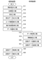
- FIG. 4 is a flowchart showing an example of the operation of a product management system in an embodiment.
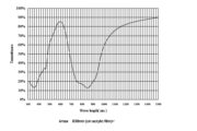
- 1 shows the spectral distribution of the absorption characteristics of an infrared absorbing dye (DY1205) in an example.
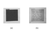
- FIG. 13 is a diagram showing examples of a photograph of a sample in an ordinary environment in which an information portion (code image) is formed using invisible yarn, and a photograph scanned with an infrared camera or an infrared sensor in the examples.
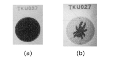
- 13A to 13C are diagrams showing examples of photographs of samples in a normal environment in which an information section (image for determining authenticity) is formed using invisible thread in an embodiment, and examples of photographs scanned with an infrared camera or infrared sensor.
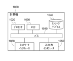
- FIG. 2 is a block diagram showing a computer that realizes a reading device and a management device in an embodiment.
- the outline of this embodiment is as follows.
- Information is provided on a textile product using a thread containing an invisible dye (hereinafter referred to as "invisible yarn”).
- the invisible dye is a dye that has a low absorptivity of visible light and a high absorptivity of light of a specific wavelength outside the visible light range (e.g., near infrared rays and ultraviolet rays). Such an invisible dye is contained.
- an invisible yarn the color due to the invisible pigment cannot be seen (or is difficult to see) under a general visible light environment.
- an invisible yarn is a yarn that has a relatively low absorptance of visible light and a relatively high absorptance of light of a predetermined wavelength outside the visible light.
- the invisible yarn reflects or transmits visible light, and absorbs light of a predetermined wavelength outside the visible light.
- a reading device infrared sensor, infrared camera
- a general visible light environment will be described as a "normal environment”.
- the invisible yarn is obtained by kneading a near-infrared absorbing dye or an ultraviolet absorbing dye (ultraviolet fluorescent dye) as an invisible dye into a raw yarn of a resin (such as PET).
- a resin such as PET
- An example using a near-infrared absorbing dye will be described below.
- the invisible dye In the case of printing, the invisible dye is generally formed on the surface, so the invisible dye comes off when washed or touched, and the function as the information part is lost in a short period of time.
- the invisible dye when invisible thread is used, the invisible dye is kneaded into the thread itself, so that it is possible to prevent the color from fading due to washing, etc., and the function as the information part can be maintained for a long period of time.
- the information portion is a code image such as a QR code (registered trademark) or a barcode, or an image (authentication image) used for authenticity determination and authentication. Security is enhanced by making code images, etc. invisible.
- a code image as an information section
- various types of management including traceability management
- the captured image is compared with a genuine image stored in advance in the management device, and if there is a certain degree of similarity or higher, it is determined to be correct.
- the information part is provided as part of the fabric of a textile product such as clothing, or as part of the main body of the textile product, or the information part is provided in the textile part of clothing, bags, shoes, camping equipment such as tents and tarps, interior seats and fabric products for automobiles, household and store goods, agricultural materials such as light-shielding sheets and heat-shielding sheets, product tags, etc.
- the information section is provided as a part of the main body of the textile product, the position and size of the information section can be freely selected without impairing the design of the textile product (for example, clothing).
- the information section to determine authenticity, counterfeiting of the product can be prevented.
- Providing the information section by printing can be done relatively easily even after the product has been manufactured.
- providing the information section using invisible thread is technically and cost-wise difficult after the product, such as clothing, has been manufactured. In other words, it becomes easy to determine whether the information section has been provided by printing or with invisible thread at the distribution stage. The specific details will be explained below.
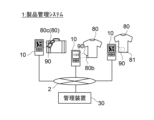
- Fig. 1 is a block diagram showing a schematic configuration of a product management system 1 according to this embodiment.
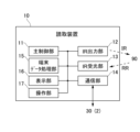
- Fig. 2 is a block diagram showing a schematic configuration of a reading device 10.
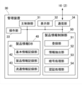
- Fig. 3 is a block diagram showing a schematic configuration of a management device 30.
- the product management system 1 is used by being incorporated into a core system such as a sales management system, an order receiving and placing system, or a production and logistics system.
- the product management system 1 performs various processes related to the product 80 by reading the information section 90 having code information provided on the product 80. Specifically, the system reads the code image of the information section 90 using the reading device 10, and accesses various data recorded in the product information DB 40 of the management device 30 based on the code image.
- the information section 90 is provided in a textile product. More specifically, the information section 90 is (1) embedded as part of the product body 81 of a textile product such as clothing, or (2) embedded in tags 80b, 80c provided separately from the product body of a product 80 such as a bag or purse.
- the tags 80b, 80c are textile products having a textile fabric, and the information section 90 is embedded in the fabric.
- an image such as a two-dimensional code or an authentication image (hereinafter referred to as a "code image") is formed using "invisible thread 96" containing a near-infrared absorbing material and "normal thread 97" (see Figure 8) not containing a near-infrared absorbing material.
- the product management system 1 comprises a reading device 10 and a management device 30.
- the reading device 10 and management device 30 are connected via a network 2, but may also be directly connected by wire or wirelessly. There may be multiple reading devices 10 connected to the management device 30.
- the network 2 may be wired or wireless, a dedicated line, or a network such as the Internet.
- the reading device 10 is a terminal device and the management device 30 is a server device, but this is not intended to be limiting.
- the reading device 10 and the management device 30 may be configured as an integrated device, some functions of the reading device 10 may be incorporated into the management device 30, or some functions of the management device 30 may be incorporated into the reading device 10.
- the reading device 10 and the management device 30 may be configured as dedicated devices, or may be configured by introducing applications or optional devices that realize the relevant functions into a smartphone or tablet terminal.
- the reading device 10 has a main control unit 11, an IR irradiation unit 12, an IR receiving unit 13, a communication unit 14, a terminal data processing unit 15, a display unit 16, and an operation unit 17.
- the reading device 10 is described as a device that reads reflected light, but it may be a device that reads transmitted light or a device that reads both reflected light and transmitted light.
- the main control unit 11 provides overall control over each component of the reading device 10.
- the communication unit 14 is an interface that communicates with the management device 30 and other external devices. In this embodiment, the communication unit 14 is connected to the network 2.
- the operation unit 17 is an interface that accepts user operations, and is composed of, for example, a keyboard, a touch panel, buttons, etc. The operation unit 17 may be configured integrally with the display unit 16.
- the IR irradiation unit 12 irradiates near-infrared light toward the information unit 90 of the product 80 in response to a user's operation on the operation unit 17.
- the near-infrared light output by the IR irradiation unit 12 there are no particular limitations on the near-infrared light output by the IR irradiation unit 12, but when it is assumed that the light is irradiated by an infrared camera or an infrared sensor (e.g., a semiconductor laser), the wavelength (peak wavelength) of the near-infrared light is assumed to be, for example, 780 nm, 830 nm, 850 nm, 940 nm, 1100 nm, 1300 nm, etc., taking into consideration the introduction cost and marketability.
- a semiconductor laser that outputs near-infrared light one that outputs the above wavelengths (780 nm, 830 nm, 850 nm, 940 nm, 1100 nm, 1300 nm) is widely used, and is therefore preferable from the standpoint of cost and technical stability.
- the wavelength of the near-infrared light selected depends on the near-infrared absorbing material used in the invisible thread 96.
- the IR light receiving unit 13 has an imaging element that reacts to near-infrared light, receives the near-infrared light irradiated from the IR irradiating unit 12 and reflected from the information unit 90 , and outputs it to the terminal data processing unit 15 .
- the IR light receiving unit 13 recognizes the light receiving level of the light irradiated to and reflected from the near-infrared absorbing material portion, i.e., the absorbing portion 91, as “LOW”, and the light receiving level of the other areas (the reflecting portion 92 and the margin 93) as “High”, and outputs them to the terminal data processing unit 15.
- the light receiving characteristics of the IR light receiving unit 13 are set according to the characteristics of the near-infrared light irradiated from the IR irradiating unit 12.
- the terminal data processing unit 15 transmits the output of the IR receiving unit 13 to the management device 30 via the communication unit 14 and displays it on the display unit 16. If it is not necessary for the reading device 10 to decode the code image in the information unit 90, the terminal data processing unit 15 converts the output of the IR receiving unit 13 into a specified data format for communication and transmits it to the management device 30. If it is necessary to decode the code image, the terminal data processing unit 15 performs a specified decoding process, converts the processing result into a specified data format for communication, and transmits it to the management device 30.
- the display unit 16 displays various information related to the reading device 10 and the management device 30, and the output from the IR light receiving unit 13.
- a code image such as the barcode or two-dimensional code in FIG. 1
- "LOW" is “black”
- “High” is “white” in terms of the light receiving level, and the processing results thereof, etc.
- the reading device 10 also has the function of reading code information that is visible under general visible light, a sensor such as a general imaging device will also be provided.
- the management device 30 includes a main control unit 31 , a display unit 32 , an operation unit 33 , a communication unit 34 , a product information DB 40 , and a product information control unit 50 .
- the main control unit 31 provides overall control over each component of the management device 30.
- the display unit 32 displays various information related to the reading device 10 and the management device 30.
- the operation unit 33 is an interface that accepts user operations and is composed of, for example, a keyboard, a touch panel, buttons, etc. The operation unit 33 may be configured integrally with the display unit 32.
- the communication unit 34 is an interface that communicates with the reading device 10 and other external devices. In this embodiment, the communication unit 34 is connected to the network 2.
- the product information DB 40 has a basic information recording section 41, a manufacturing information recording section 42, and a distribution information recording section 43.
- the product information DB 40 is illustrated as being divided into the basic information recording section 41, the manufacturing information recording section 42, and the distribution information recording section 43, but this is not intended to be limiting, and they may be integrated, integrated with other components, or further subdivided.
- the data recorded in the product information DB 40 may be data in a format that is not encrypted, or may be data in an encrypted format such as a blockchain.
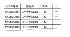
- the basic information recording unit 41 records the basic information of the product 80 when the information unit 90 is provided directly on the product 80, and records the basic information of the product 80 to which the tags 80b and 80c are attached when the information unit 90 is provided on the tags 80b and 80c of the product 80.
- Figure 4 shows an example of data (example of basic information) recorded in the basic information recording unit 41.
- the basic information is, for example, a serial number, product name, size, etc.
- the serial number is extracted, and the various data recorded in the product information DB 40 is referenced using the serial number as a key.
- the manufacturing information recording unit 42 records manufacturing information.
- FIG. 5 shows an example of data (an example of manufacturing information) recorded in the manufacturing information recording unit 42.
- the manufacturing information is, for example, the manufacturing date and time, the manufacturing plant, and the lot numbers of the parts and raw materials actually used to manufacture the product 80, and is recorded in association with the serial number of the product 80.
- the distribution information recording unit 43 records various information regarding the distribution and sales processes after the final product 80 is shipped.
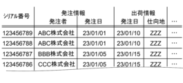
- FIG. 6 shows an example of data recorded in the distribution information recording unit 43.
- information recorded in the distribution information recording unit 43 is order information, shipping information, price information, customer information, etc., and is recorded in association with a serial number.
- the serial number, order information (orderer name, order date), and shipping information (shipping date, destination) are recorded.
- the product information control unit 50 includes a registration unit 51, an information extraction unit 52, an encryption processing unit 53, and an authentication processing unit 54.
- the registration unit 51 registers and records various information in the product information DB 40 (basic information recording unit 41, manufacturing information recording unit 42, distribution information recording unit 43) and updates it as appropriate.
- the information extraction unit 52 extracts the necessary information from the product information DB 40 in response to such a request.
- the extracted information is displayed on the display unit 32 or transmitted to the reading device 10 or another device in response to the request.
- the encryption processing unit 53 performs a decoding process. In addition, when performing encryption and decryption processes such as a block chain on the data to be recorded in the product information DB 40, the encryption processing unit 53 performs encryption and decryption processes according to the format.
- the authentication processing unit 54 authenticates the access of the person using the management device 30, and determines whether the information read from the information unit 90 is appropriate, in other words, the authenticity of the product 80.
- the authenticity determination process of the product 80 may be performed using a two-dimensional code or the like, but it can also be performed, for example, by providing an authentication image in the information unit 90 with invisible thread 96 instead of a two-dimensional code or the like, and sensing whether the authentication image is correct and whether the authentication image is present.
- a genuine authentication image for example, a reference authentication image
- the authentication processing unit 54 determines the similarity between the captured image and the reference authentication image, and if the similarity is equal to or greater than a certain level, it determines (authenticates) that the captured image is a correct authentication image.
- known methods can be used to determine the similarity, such as methods that evaluate SIFT features, hash values, histogram matching, structural similarity (SSIM) index, etc., or technologies that apply such methods to machine learning or AI (artificial intelligence).
- FIG. 13 is a diagram illustrating an example of the hardware configuration of a computer 1000 for implementing the reading device 10 and the management device 30.
- the computer 1000 may be any of a variety of computers.
- the computer 1000 may be a personal computer (PC), a server machine, a tablet terminal, a smartphone, or a terminal device.
- the computer 1000 may be a dedicated computer designed to implement the reading device 10 and the management device 30, or may be a general-purpose computer.
- the computer 1000 has a bus 1010, a processor 1020, a memory 1030, a storage device 1040, an input/output interface 1050, and a network interface 1060.
- the bus 1010 is a data transmission path through which the processor 1020, the memory 1030, the storage device 1040, the input/output interface 1050, and the network interface 1060 transmit and receive data to and from each other.
- the processor 1020 is an arithmetic processing device such as a CPU (Central Processing Unit) or a GPU (Graphics Processing Unit).
- the memory 1030 is a main storage device constituted by a RAM (Random Access Memory) or the like.
- the storage device 1040 is an auxiliary storage device constituted by a hard disk, an SSD (Solid State Drive), a memory card, a ROM (Read Only Memory), or the like. However, the storage device 1040 may be constituted by a RAM or the like.
- the input/output interface 1050 is an interface for connecting the computer 1000 to an input/output device. For example, input devices such as a keyboard and a mouse, and output devices such as a display device are connected to the input/output interface 1050.
- the network interface 1060 is an interface for connecting to a communication network such as a WAN (Wide Area Network) or a LAN (Local Area Network).
- the storage device 1040 stores program modules that realize the various functions of the reading device 10 and the management device 30.
- the processor 1020 reads each of these program modules into the memory 1030 and executes them to realize the various functions corresponding to the program modules.
- the computer 1000 is a server that functions as the management device 30, and is connected to the reading device 10 so that it can communicate with the reading device 10.
- the administrator of the management device 30 installs an application that realizes the management device 30 on the server and runs it.
- the computer 1000 is a terminal device that functions as the reading device 10 and is communicably connected to the management device 30.
- the user of the reading device 10 installs an application that realizes the functions of the reading device 10 on the terminal device and runs it.
- the reading device 10 and management device 30 implemented by such a computer 1000 can be used to implement processing by the product management system 1 (reading device 10 and management device 30).
- a specific example of the operation of the product management system 1 (reading device 10 and management device 30) will be described later with reference to the flowchart in FIG. 9.
- Figure 7 is an enlarged view of the information section 90 formed of invisible thread 96 and its surroundings.
- Figure 7(a) shows the state under normal visible light.
- Figure 7(b) shows the state read by the reading device 10, i.e., the state where the IR irradiation section 12 irradiates near-infrared light and the IR light receiving section 13 reads the reflected light.
- a two-dimensional code image is shown as an example of the code image of the information section 90.
- the information section 90 is provided directly on the fabric 94.
- the information section 90 has an absorbing section 91 and a reflective section 92.
- the absorbing section 91 and the reflective section 92 form a code image.
- margins 93 are provided on the top, bottom, left, and right outer periphery of the information section 90 (i.e., the code image formed by the absorbing section 91 and the reflective section 92).
- the contrast difference between the absorbing section 91 and the reflective section 92 when the reading device 10 reads the information section 90 is recognized as the code image.
- the absorbing portion 91 is formed of invisible threads 96 containing a near-infrared absorbing material that absorbs near-infrared rays, and is a portion that is recognized as "black" in the image of the two-dimensional code. It is necessary that the absorbing portion 91 is not visible under a normal viewing environment. Therefore, the invisible threads 96 that constitute the absorbing portion 91 are configured so that they blend in with the surroundings and cannot be grasped as a code image under a normal viewing environment. For example, if the surrounding color (i.e., the reflective portion 92, etc.) is solid blue, the color of the invisible threads 96 of the absorbing portion 91 is also blue.
- the invisible threads 96 are made to be a color that constitutes the design. It is also possible to form a design image on the upper part of the normal thread 97 with the normal thread 97.
- the near-infrared absorbing material will be described later.
- the reflective portion 92 is formed from normal thread 97 that does not contain near-infrared absorbing material, and is the portion that is recognized as "white” in the image of the two-dimensional code.
- “not containing near-infrared absorbing material” means not only that it does not contain materials that absorb only near-infrared light, but also that it does not contain materials that absorb both near-infrared light and light other than near-infrared light, such as carbon.
- the reflective portion 92 is recognized as "white” when the light reflected by the reflective portion 92 is received by the IR light receiving portion 13.
- the margin 93 is also called the quiet zone, and is an area of a certain width that is recognized as "white” like the reflective area 92.
- the presence of the margin 93 allows the start and end positions of the code image to be properly determined, and is generally determined according to the standard for the code image.
- the code image of the information section 90 may be formed by embroidering invisible thread 96 at the position of the absorbing section 91, or may be formed as a code image design on a piece of fabric (textile product such as woven fabric or knitted fabric) using invisible thread 96 and normal thread 97.
- a two-dimensional code image can be formed using invisible thread 96 and normal thread 97.
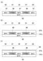
- 8 is a diagram showing a cross-sectional structure of the information section 90. Three types of structure examples are shown here. 8(a) shows an example in which invisible thread 96 and normal thread 97 (non-IR thread color system) are provided in a single layer structure in the thickness direction on the surface side of a base cloth 95.
- the base cloth 95 is, for example, a white cloth or a cloth that reduces the transmission of near-infrared rays.
- the invisible thread 96 constituting the absorbing section 91 is exposed on the surface, so that the information section 90 can be recognized with high accuracy when sensed with near-infrared rays.
- the base material cloth 95 is necessary, but when the invisible thread 96 is applied as a woven or knitted fabric, the base material cloth 95 is not essential, and the two-dimensional code image can be formed using only the invisible thread 96 and the normal thread 97.
- the code image can be optimized by adjusting the thickness and width of the layer formed by the invisible thread 96 and the normal thread 97, the amount and concentration of the near-infrared absorbing material contained in the invisible thread 96, and the pigment that develops the color in a visual environment.
- such adjustments make it possible to select whether the information unit 90 is a type that acquires light reflected by the information unit 90 or a type that acquires transmitted light when acquiring a code image.
- the type of information unit 90 determines whether the reading device 10 used is a type that receives reflected light or a type that receives transmitted light.
- FIG. 8(b) shows an example of a structure in which a layer formed of normal thread 97 is layered on an absorbing section 91 formed of invisible thread 96 on the surface side of a base cloth 95. That is, an information section 90 formed of invisible thread 96 and normal thread 97 as a first layer 97a is provided on the base cloth 95. A second layer 97b formed of normal thread 97 is further formed on top of that. If the invisible thread 96 is exposed on the surface, the presence of the information section 90 may be recognized by the amount of light or the touch. Therefore, such concerns can be avoided by providing a layer of normal thread 97 on the information section 90 (i.e., the absorbing section 91 of the invisible thread 96). The thickness of the layer of normal thread 97 provided on the absorbing section 91 is adjusted according to the characteristics of the invisible thread 96 and the normal thread 97.
- FIG. 8(c) shows a configuration in which a cover layer 98 is further provided on the second layer 97b of the normal thread 97 of the configuration shown in FIG. 8(b).
- the cover layer 98 is formed of a material and with a thickness that does not affect the recognition of the information section 90.
- any material that has a high transmittance for near-infrared light and visible light may be used, and may be a fiber fabric or a film material.
- the information section 90 (absorbing section 91, reflecting section 92) from the invisible thread 96 and the normal thread 97, a code image that cannot be seen by the naked eye under normal viewing conditions and can be read by irradiating near-infrared light can be provided on the textile product.
- the code information i.e., the absorbing section 91
- the code image is virtually never erased, compared to when it is formed by printing.
- near-infrared absorbing materials may be prone to decomposition when exposed to the atmosphere, they are difficult to decompose because they are kneaded into the raw thread, and the code image can be used for a long period of time. In other words, even in a state where the traceability function of the product 80 would be virtually lost in the past, this embodiment can suppress deterioration of the traceability function.
- the invisible thread 96 may be a multifilament made of multiple long fibers, or a monofilament made of one long fiber. From the viewpoint of near-infrared absorption characteristics (i.e., high absorption characteristics), a multifilament (twisted thread) is preferable. There is no limit to the thickness of the invisible thread 96, and it is appropriately selected depending on the weaving method and the coarseness of the fabric of the product 80 itself.
- the fiber cross section of the invisible thread 96 may be, for example, circular, irregular, hollow, etc. However, the specifications of the invisible thread 96 are selected depending on the fineness of the code image included in the information section 90, that is, how large the dots should be.
- the invisible thread 96 is obtained by incorporating a near-infrared absorbing dye into the resin thread. As described above, various dyes are incorporated as necessary to obtain a color that can be recognized under normal visual conditions.
- Resin yarns can be made from any resin that is transparent and capable of containing pigments.
- resins such as polyester resin, nylon resin, acrylic resin, and polycarbonate resin can be used.
- PET polyethylene terephthalate
- PET is inexpensive, has excellent heat resistance and strength, is lightweight, and has good dyeability. It is possible to change the shape of the yarn during production or knead other materials into it to give it special properties, making it an ideal choice.
- near-infrared absorbing materials or dyes In terms of incorporating near-infrared absorbing materials or dyes into resin, it is sufficient if the resin and near-infrared absorbing dyes can be melted or appropriately atomized and dispersed at the melting temperature of the resin without being thermally decomposed. As a result, a wide variety of combinations of materials, colors, thicknesses, etc. can be realized as invisible threads 96. In other words, by using invisible threads 96, it is possible to substantially eliminate any effect on the materials and design of the textile product.
- the near-infrared absorbing material whether it is an organic material or an inorganic material.
- organic material cyanine compounds, phthalocyanine compounds, naphthalocyanine compounds, anthraquinone compounds, dithiol metal complexes, aminium, immonium compounds, azo compounds, and the like can be used.
- Inorganic materials include LaB6 (lanthanum hexaboride), CWO (registered trademark, cesium-doped tungsten oxide), and conventional materials such as ITO (tin-doped indium oxide) and ATO (antimony-doped tin oxide), which may be used alone or in appropriate mixture with organic materials.
- naphthalocyanine compound is a general term for a metal naphthalocyanine compound having a substituent, a metal-free naphthalocyanine compound having a substituent, a metal naphthalocyanine compound having no substituent, and a metal-free naphthalocyanine compound having no substituent.
- These compounds exhibit excellent near-infrared light absorption performance. Specifically, they have maximum absorption characteristics (maximum absorption wavelength) in the range of 700 nm to 1300 nm in the absorption distribution. More specifically, they are materials that satisfy the above-mentioned physical properties and can absorb near-infrared light output from an infrared camera or infrared sensor (e.g., semiconductor laser) at wavelengths such as 780 nm, 830 nm, 850 nm, 1100 nm, and 1300 nm, and have low absorption characteristics in the visible light region (e.g., 400 nm to 700 nm).
- infrared camera or infrared sensor e.g., semiconductor laser
- Dye DY1202 (manufactured by Yamamoto Chemical Industry Co., Ltd.): Maximum absorption wavelength near 780 nm Dye DY1205 (manufactured by Yamamoto Chemical Industry Co., Ltd.): Maximum absorption wavelength near 830 nm Dye DY2001 (manufactured by Yamamoto Chemical Industry Co., Ltd.): Maximum absorption wavelength near 850 nm Dye DY1204 (manufactured by Yamamoto Chemical Industry Co., Ltd.): Maximum absorption wavelength near 1100 nm
- the maximum absorption wavelength (peak wavelength ⁇ ) can be adjusted by appropriately adjusting the components of the materials constituting the above dyes.
- the light absorption rate at the maximum absorption wavelength is 50% or more.
- the light absorption rate at the peak wavelength ⁇ is preferably 60% or more, more preferably 80% or more. It is appropriately determined according to the performance of the reading device 10.
- the light absorption rate in the range of wavelength width 300 nm i.e., the range of ⁇ 150 nm
- the half-value width is preferably 100 nm or less, more preferably 50 nm or less. This improves the sensing accuracy of the information portion 90 (i.e., the code image).
- the half-value width is also determined appropriately depending on the performance of the reading device 10.
- phthalocyanine compounds and naphthalocyanine compounds are preferred because they have more favorable near-infrared absorption performance and it is easy to adjust the black value density during sensing by changing the content.
- the pigment-based compounds have good performance in terms of weather resistance (durability), i.e., they are highly capable of maintaining the function of the invisible yarn 96 containing the near-infrared absorbing material. Furthermore, in consideration of the durability of dye images, naphthalocyanine compounds are preferred because they have a more expanded ⁇ -conjugated system than phthalocyanine compounds, resulting in a so-called rigid structure and excellent weather resistance. In order to shift the absorption band of the phthalocyanine compound and the naphthalocyanine compound to a desired near-infrared region, adjustments such as introduction of a substituent or changing the metal are required.
- a vanadyl naphthalocyanine compound which may have as a substituent one or more of a nitro group, a substituted or unsubstituted alkyl group, a substituted or unsubstituted aryl group, and a substituted or unsubstituted alkylamino group
- a copper naphthalocyanine compound which may have as a substituent one or more of a nitro group, a substituted or unsubstituted alkyl group, a substituted or unsubstituted aryl group, and a substituted or unsubstituted alkylamino group
- a vanadyl naphthalocyanine compound which may have as a substituent one or more of a nitro group, a substituted or unsubstituted alkyl group, a substituted or unsubstituted aryl group, and a substituted or unsubstituted alkylamino group
- the performance of organic near-infrared absorbing materials deteriorates when exposed to the atmosphere or ultraviolet rays, etc., but if the rate of deterioration is slow, the materials can function as invisible thread 96 materials without taking any special measures against deterioration.
- the near-infrared absorbing material may be dispersed, melt-dispersed, or dissolved in fine particles having an average particle size of 0.5 microns or less, preferably 0.3 microns or less, more preferably 0.2 microns or less, and particularly preferably 0.1 microns or less.
- the method for atomizing the near infrared absorbing material is not particularly limited, and may be either a dry method or a wet method, and may be a sand mill method, a ball mill method, a spike mill method, etc. When mixing, an additive that helps atomization or stabilization may be added as necessary.
- the numerical range of the near-infrared absorbing material content varies depending on the properties of the near-infrared absorbing material. However, regardless of the type of near-infrared absorbing material content, if the content is insufficient, near-infrared light will not be absorbed sufficiently.
- the IR light receiving unit 13 acquires the reflected near-infrared light from the information unit 90 (S13: light receiving process), outputs the light level irradiated to the absorbing unit 91 as "LOW" and the light level irradiated to other areas (such as the reflecting unit 92 and margin 93) as "High” to the terminal data processing unit 15 (S14: light receiving data output process).
- the code image of the information unit 90 is output as black and white image data.
- the terminal data processing unit 15 also causes the acquired code image to be displayed on the display unit 16 (S15: code image display process).
- the reading device 10 acquires instructions from the user regarding the content of the process to be executed (S16: execution process acquisition step).
- the process to be executed may be predetermined and executed automatically.
- the content of the process to be executed will be described as a display process of "product name" and "raw materials.”
- the terminal data processing unit 15 transmits the acquired code image data and the process to be executed to the management device 30 (S17: data notification step). If the code image is decoded by the reading device 10, the decoded result is transmitted instead of the code image. If the process to be executed can be completed by the reading device 10 alone, the predetermined process is executed in the reading device 10, and the execution result is displayed on the display unit 16, for example.
- the encryption processing unit 53 decodes the code image from the reading device 10 and extracts the information superimposed on the code image (S19: information extraction process). For example, if the information superimposed on the code image is the serial number of the product 80, the serial number is extracted. At this time, an authentication process (authentication process process) of the code image or the superimposed information may also be performed.
- the authentication process may use a code image (barcode, etc.), or may use an authentication image prepared separately from the code image as described above.
- the information extraction unit 52 uses the serial number obtained from the code image as a key to extract data corresponding to the processing to be executed received from the reading device 10 from the product information DB 40 (S20: response data selection process), and transmits this together with the serial number to the reading device 10 (S21: response data transmission process).
- the request from the reading device 10 was for "product name” and "raw materials”
- it uses the serial number as a key to extract "product name” from the basic information recording unit 41 and "raw materials” from the manufacturing information recording unit 42.
- the terminal data processing unit 15 causes the display unit 16 to display the response data (here, the serial number, "product name,” and "raw materials") (S23: response data display step). If another process is to be continued, the reading device 10 notifies the management device 30 of an execution instruction in response to a user operation.
- the display process of data recorded in the product information DB 40 has been exemplified here, for example, in the case of processing at the distribution stage, it is possible to perform processing such as updating the number of stock items according to the shipping status and the warehouse in which the stock is stored. Furthermore, in the case of processing at the retail stage, it is possible to perform sales management and customer information management processing that associates products with customers.
- the information section 90 is read in one direction (either the front or back side), but it may be read from both the front and back sides. That is, the light irradiation step includes a first light irradiation step of irradiating light (A) onto the front surface of the information section 90, and a second light irradiation step of irradiating light (A) onto the back surface of the information section 90.
- the light receiving step includes a first light receiving step of receiving light (A) from the first light irradiation step, and a second light receiving step of receiving light (A) from the second light irradiation step.
- the information extraction step includes a first information extraction step of extracting first information from the information section based on the light (A) obtained in the first light receiving step, and an extracted second information extraction step of extracting second information from the information section 90 based on the light (A) obtained in the second light receiving step.
- the authentication step performs authentication when the first information and the second information are correct. For example, if the information section 90 is disguised by printing on the front side, it can be correctly recognized when the front side is read, but it may not be correctly read when the back side is read. Therefore, by reading both sides, such disguise can be prevented.
- a textile product (product 80, product body 81, tags 80b, 80c) having an information section 90 provided in a predetermined shape on a textile fabric made of thread (normal thread) that does not absorb light of the specific wavelength ⁇ , using functional thread (invisible thread) that absorbs light whose peak wavelength is a specific wavelength ⁇ outside the visible light range.
- the fiber cross section of the functional yarn may be circular, irregular, hollow, or the like.
- the textile product (product 80, product body 81, tags 80b, 80c) according to any one of 1. to 3., in which the light absorptance of the specific wavelength ⁇ is 50% or more.
- the light absorptance is preferably 60% or more, more preferably 80% or more. It is appropriately determined depending on the performance of the reading device 10.
- the half-value width is preferably 100 nm or less, and more preferably 50 nm or less.
- the functional yarn is a monofilament yarn or a multifilament yarn in which a plurality of fibers are twisted together (product 80, product body 81, tags 80b, 80c).
- the information portion 90 is formed by embroidering the functional thread on the textile fabric (product 80, product body 81, tags 80b, 80c).
- the base cloth 95 is not essential, and the two-dimensional code image can be formed using only the invisible thread 96 and the normal thread 97. 11.
- the information section 90 is formed by weaving or knitting together the functional yarn and a yarn that does not absorb light of the specific wavelength ⁇ .
- 12. 1. The textile product according to any one of 1. to 11., wherein in the information section 90, the functional yarn and the yarn that does not absorb light of the specific wavelength ⁇ have the same color or a similar color in the visible light range (product 80, product body 81, tags 80b, 80c).
- 13. The textile product according to any one of 1. to 12., wherein in the information section 90, a cover layer that transmits light of the specific wavelength ⁇ is provided on an upper surface of the functional yarn (product 80, product body 81, tags 80b, 80c). 14. 13.
- the invisible yarn was obtained by the following steps.
- An infrared absorbing dye (DY1205 (manufactured by Yamamoto Chemical Industry Co., Ltd.) was added to the molten polyethylene terephthalate to a concentration of 0.30% by mass, and the infrared absorbing dye was melt-dispersed in the polyethylene terephthalate.
- the obtained spinning solution was red and transparent. This spinning solution was discharged from a spinneret with a hole diameter of 0.8 mm ⁇ 18 holes at a spinning temperature of 280° C.
- the produced filament yarn had a circular cross-sectional shape in a direction perpendicular to the fiber axis direction and a fiber diameter of 0.104 mm. 10 shows the spectral distribution of the absorption characteristics of the infrared absorbing dye (DY1205). The maximum absorption wavelength was 838 nm.
- Figure 11 is a photograph of a sample in which a code image was generated as the information section.
- Figure 11(a) is a photograph taken under normal conditions.
- Figure 11(b) is a photograph scanned with an infrared camera or infrared sensor.
- Figure 12 is a photograph of a sample in which an image for authenticity determination was generated as the information section.
- Figure 12(a) is a photograph taken under normal conditions.
- Figure 12(b) is a photograph scanned with an infrared camera or infrared sensor.
- code image code image
- the image for authenticity determination it was difficult to visually recognize the information section (code image) under normal conditions (i.e., under visible light).
Landscapes
- Engineering & Computer Science (AREA)
- Textile Engineering (AREA)
- Mechanical Engineering (AREA)
- Chemical & Material Sciences (AREA)
- Chemical Kinetics & Catalysis (AREA)
- General Chemical & Material Sciences (AREA)
- Physics & Mathematics (AREA)
- General Physics & Mathematics (AREA)
- Theoretical Computer Science (AREA)
- Manufacturing & Machinery (AREA)
- Woven Fabrics (AREA)
- Yarns And Mechanical Finishing Of Yarns Or Ropes (AREA)
Priority Applications (5)
| Application Number | Priority Date | Filing Date | Title |
|---|---|---|---|
| EP24750262.8A EP4660357A1 (en) | 2023-01-31 | 2024-01-30 | Fiber product, functional thread, and sensing method |
| JP2024574924A JPWO2024162313A1 (cg-RX-API-DMAC7.html) | 2023-01-31 | 2024-01-30 | |
| KR1020257028573A KR20250141751A (ko) | 2023-01-31 | 2024-01-30 | 섬유 제품, 기능성 실 및 센싱 방법 |
| US19/151,715 US20260226660A1 (en) | 2023-01-31 | 2024-01-30 | Textile product, functional yarn, and sensing method |
| CN202480009740.3A CN120898034A (zh) | 2023-01-31 | 2024-01-30 | 纤维制品、功能性纱、及感测方法 |
Applications Claiming Priority (2)
| Application Number | Priority Date | Filing Date | Title |
|---|---|---|---|
| JP2023012962 | 2023-01-31 | ||
| JP2023-012962 | 2023-01-31 |
Publications (1)
| Publication Number | Publication Date |
|---|---|
| WO2024162313A1 true WO2024162313A1 (ja) | 2024-08-08 |
Family
ID=92146846
Family Applications (1)
| Application Number | Title | Priority Date | Filing Date |
|---|---|---|---|
| PCT/JP2024/002783 Ceased WO2024162313A1 (ja) | 2023-01-31 | 2024-01-30 | 繊維製品、機能性糸、およびセンシング方法 |
Country Status (7)
| Country | Link |
|---|---|
| US (1) | US20260226660A1 (cg-RX-API-DMAC7.html) |
| EP (1) | EP4660357A1 (cg-RX-API-DMAC7.html) |
| JP (1) | JPWO2024162313A1 (cg-RX-API-DMAC7.html) |
| KR (1) | KR20250141751A (cg-RX-API-DMAC7.html) |
| CN (1) | CN120898034A (cg-RX-API-DMAC7.html) |
| TW (1) | TW202447009A (cg-RX-API-DMAC7.html) |
| WO (1) | WO2024162313A1 (cg-RX-API-DMAC7.html) |
Cited By (1)
| Publication number | Priority date | Publication date | Assignee | Title |
|---|---|---|---|---|
| WO2026164056A1 (ja) * | 2025-01-28 | 2026-08-06 | 山本化成株式会社 | 識別媒体 |
Citations (6)
| Publication number | Priority date | Publication date | Assignee | Title |
|---|---|---|---|---|
| JPH0792911A (ja) * | 1992-12-17 | 1995-04-07 | Satake:Kk | 識別体および識別方法 |
| JPH09160996A (ja) * | 1995-12-11 | 1997-06-20 | A D S:Kk | コードの作成方法とその読取装置 |
| JP2008181447A (ja) * | 2007-01-26 | 2008-08-07 | Colorzip Japan Inc | 励起発色のカラーコードとその解読方法 |
| CN101864605A (zh) * | 2010-06-09 | 2010-10-20 | 蚌埠市瑞进防伪材料科技有限公司 | 一种近红外吸收防伪纤维及其制备方法 |
| JP2018089840A (ja) | 2016-12-02 | 2018-06-14 | 小林クリエイト株式会社 | 印刷物の製造方法 |
| JP2023012962A (ja) | 2021-07-14 | 2023-01-26 | 赤石 維衆 | 事前固形物分離型浄化槽など |
-
2024
- 2024-01-30 EP EP24750262.8A patent/EP4660357A1/en active Pending
- 2024-01-30 WO PCT/JP2024/002783 patent/WO2024162313A1/ja not_active Ceased
- 2024-01-30 CN CN202480009740.3A patent/CN120898034A/zh active Pending
- 2024-01-30 US US19/151,715 patent/US20260226660A1/en active Pending
- 2024-01-30 JP JP2024574924A patent/JPWO2024162313A1/ja active Pending
- 2024-01-30 TW TW113103581A patent/TW202447009A/zh unknown
- 2024-01-30 KR KR1020257028573A patent/KR20250141751A/ko active Pending
Patent Citations (6)
| Publication number | Priority date | Publication date | Assignee | Title |
|---|---|---|---|---|
| JPH0792911A (ja) * | 1992-12-17 | 1995-04-07 | Satake:Kk | 識別体および識別方法 |
| JPH09160996A (ja) * | 1995-12-11 | 1997-06-20 | A D S:Kk | コードの作成方法とその読取装置 |
| JP2008181447A (ja) * | 2007-01-26 | 2008-08-07 | Colorzip Japan Inc | 励起発色のカラーコードとその解読方法 |
| CN101864605A (zh) * | 2010-06-09 | 2010-10-20 | 蚌埠市瑞进防伪材料科技有限公司 | 一种近红外吸收防伪纤维及其制备方法 |
| JP2018089840A (ja) | 2016-12-02 | 2018-06-14 | 小林クリエイト株式会社 | 印刷物の製造方法 |
| JP2023012962A (ja) | 2021-07-14 | 2023-01-26 | 赤石 維衆 | 事前固形物分離型浄化槽など |
Non-Patent Citations (1)
| Title |
|---|
| See also references of EP4660357A1 |
Cited By (1)
| Publication number | Priority date | Publication date | Assignee | Title |
|---|---|---|---|---|
| WO2026164056A1 (ja) * | 2025-01-28 | 2026-08-06 | 山本化成株式会社 | 識別媒体 |
Also Published As
| Publication number | Publication date |
|---|---|
| US20260226660A1 (en) | 2026-08-06 |
| TW202447009A (zh) | 2024-12-01 |
| KR20250141751A (ko) | 2025-09-29 |
| EP4660357A1 (en) | 2025-12-10 |
| CN120898034A (zh) | 2025-11-04 |
| JPWO2024162313A1 (cg-RX-API-DMAC7.html) | 2024-08-08 |
Similar Documents
| Publication | Publication Date | Title |
|---|---|---|
| US20230243088A1 (en) | Apparel Collection Management with Product Modifications | |
| EP1254427B1 (en) | Authenticating textile based items | |
| CN1279849A (zh) | 用于货品鉴别的系统和方法 | |
| JP2008181447A (ja) | 励起発色のカラーコードとその解読方法 | |
| EP4660357A1 (en) | Fiber product, functional thread, and sensing method | |
| EP1548664A1 (en) | Customer age verification | |
| US11702783B2 (en) | Preventing degradation of stored base templates before laser finishing | |
| JP4408189B2 (ja) | 偽造防止用テープとその製造法 | |
| WO2024162312A1 (ja) | 読取装置、管理システム、繊維製品および管理方法 | |
| JP2808786B2 (ja) | 不可視識別マークの記録された繊維布帛 | |
| EP0269542B1 (en) | Textil label | |
| JP4549119B2 (ja) | 識別媒体および識別媒体を備えた物品 | |
| CN112508582B (zh) | 一种多重隐形模纹防伪系统 | |
| CN206788901U (zh) | 具有隐藏标识码的衣服标签及衣服 | |
| Shamey | Anti-Counterfeit Textile Substrates Using Covert Taggants. | |
| Sugiyama et al. | Weaving and Disguising Infrared Markers toward Invisible Textile Interaction | |
| US20250148230A1 (en) | Authentication elements for authenticating objects and systems, objects, and methods using them | |
| CN102169651A (zh) | 一种复合纤维标志标签防伪方法 | |
| JP2530783B2 (ja) | 光学読み取りマ―ク記録布帛およびその製造方法 | |
| JP2003119660A (ja) | 電子透かしコード内在布帛着色物を利用した管理システム | |
| KR20220081098A (ko) | 식별력이 향상된 시트벨트 웨빙 | |
| Hua et al. | An experimental study of multicolored composite yarns for woven fabrics by the friction spinning method | |
| JP2014148149A (ja) | 印刷物の製造方法、インクジェットプリンタ、及び印刷方法 | |
| JP2001288672A (ja) | バーコードパターンが形成された布製品 | |
| McCutcheon | Too many stitches in time? The Polo Lauren case, non-infringing accessories and the copyright/design overlap defence |
Legal Events
| Date | Code | Title | Description |
|---|---|---|---|
| 121 | Ep: the epo has been informed by wipo that ep was designated in this application |
Ref document number: 24750262 Country of ref document: EP Kind code of ref document: A1 |
|
| ENP | Entry into the national phase |
Ref document number: 2024574924 Country of ref document: JP Kind code of ref document: A |
|
| WWE | Wipo information: entry into national phase |
Ref document number: 2024574924 Country of ref document: JP |
|
| WWE | Wipo information: entry into national phase |
Ref document number: 202480009740.3 Country of ref document: CN |
|
| ENP | Entry into the national phase |
Ref document number: 1020257028573 Country of ref document: KR Free format text: ST27 STATUS EVENT CODE: A-0-1-A10-A15-NAP-PA0105 (AS PROVIDED BY THE NATIONAL OFFICE) |
|
| NENP | Non-entry into the national phase |
Ref country code: DE |
|
| WWP | Wipo information: published in national office |
Ref document number: 202480009740.3 Country of ref document: CN |
|
| WWP | Wipo information: published in national office |
Ref document number: 2024750262 Country of ref document: EP |