WO2024162194A1 - 層流素子、流量センサ及びマスフローコントローラ - Google Patents
層流素子、流量センサ及びマスフローコントローラ Download PDFInfo
- Publication number
- WO2024162194A1 WO2024162194A1 PCT/JP2024/002357 JP2024002357W WO2024162194A1 WO 2024162194 A1 WO2024162194 A1 WO 2024162194A1 JP 2024002357 W JP2024002357 W JP 2024002357W WO 2024162194 A1 WO2024162194 A1 WO 2024162194A1
- Authority
- WO
- WIPO (PCT)
- Prior art keywords
- flow
- laminar flow
- flow element
- laminar
- length
- Prior art date
- Legal status (The legal status is an assumption and is not a legal conclusion. Google has not performed a legal analysis and makes no representation as to the accuracy of the status listed.)
- Ceased
Links
Images




Classifications
-
- G—PHYSICS
- G01—MEASURING; TESTING
- G01F—MEASURING VOLUME, VOLUME FLOW, MASS FLOW OR LIQUID LEVEL; METERING BY VOLUME
- G01F1/00—Measuring the volume flow or mass flow of fluid or fluent solid material wherein the fluid passes through a meter in a continuous flow
- G01F1/68—Measuring the volume flow or mass flow of fluid or fluent solid material wherein the fluid passes through a meter in a continuous flow by using thermal effects
- G01F1/684—Structural arrangements; Mounting of elements, e.g. in relation to fluid flow
-
- G—PHYSICS
- G01—MEASURING; TESTING
- G01F—MEASURING VOLUME, VOLUME FLOW, MASS FLOW OR LIQUID LEVEL; METERING BY VOLUME
- G01F1/00—Measuring the volume flow or mass flow of fluid or fluent solid material wherein the fluid passes through a meter in a continuous flow
-
- G—PHYSICS
- G01—MEASURING; TESTING
- G01F—MEASURING VOLUME, VOLUME FLOW, MASS FLOW OR LIQUID LEVEL; METERING BY VOLUME
- G01F1/00—Measuring the volume flow or mass flow of fluid or fluent solid material wherein the fluid passes through a meter in a continuous flow
- G01F1/76—Devices for measuring mass flow of a fluid or a fluent solid material
Definitions
- the present invention relates to a laminar flow element used in a flow sensor, a flow sensor including the laminar flow element, and a mass flow controller including the flow sensor.
- a laminar flow element is a component that has the function of arranging the flow of a fluid to form a laminar flow.
- the main application of laminar flow elements is as a flow sensor.
- the laminar flow element is inserted into a bypass flow path that bypasses the sensor tube of the flow sensor, and keeps the ratio of the flow rate of the fluid flowing through the sensor tube to the flow rate of the fluid flowing through the bypass flow path (hereinafter sometimes referred to as the "division ratio"). Since most of the fluid passes through the bypass flow path, the flow rate of the fluid flowing through the sensor tube does not exceed the rated value. This allows the total flow rate to be accurately estimated from the flow rate value measured in the sensor tube.
- the laminar flow element inserted into the bypass flow path is sometimes called a bypass.
- the laminar flow element is inserted into the main flow path, and causes a pressure loss in the fluid flowing inside.
- the flow rate of the fluid can be measured by measuring the pressure difference between the inlet and outlet sides of the laminar flow element.
- Mass flow controllers are used to supply gas at a constant flow rate to semiconductor manufacturing equipment. Mass flow controllers are equipped with an internal flow sensor. When the flow sensor of a mass flow controller is the thermal flow sensor or differential pressure flow sensor described above, the flow sensor is equipped with a laminar flow element. There are several types of structures for the laminar flow element that constitutes the flow sensor of a mass flow controller. For example, those that bundle a large number of capillary tubes and those that are made of corrugated sheets are known. All of these laminar flow elements have a complex structure and require skill to assemble.
- Patent Documents 1 and 2 describe inventions of laminar flow elements configured by stacking multiple plate-like members with many circular or regular hexagonal holes so that the direction of fluid flow is perpendicular to the surface of the plate-like members.
- Patent Documents 3 to 5 and Patent Document 6, which is filed by the applicant describe inventions of laminar flow elements configured by stacking multiple plate-like members with elongated rectangular slots so that the direction of fluid flow is parallel to the surface of the plate-like members.
- the flow paths are formed using etching and diffusion bonding techniques, so assembly does not require skill.
- the laminar flow element is inserted into the flow path through which the greatest volume of fluid flows, and so the laminar flow element is one of the components that determines the upper limit of the flow rate.
- the flow path is composed of many holes, and the proportion of the area of the flow path in the cross-sectional area of the laminar flow element was inevitably small due to the walls that defined the holes. This resulted in the problem that the flow rate could not be increased significantly.
- the flow division ratio may change in the range of flow rates from zero to the maximum flow rate, and the relationship between the output of the flow sensor and the actual flow rate may deviate from a directly proportional relationship. This poses the problem that the measurement accuracy of the flow sensor cannot be increased significantly.
- the present invention was made in consideration of the above problems, and aims to provide a laminar flow element used as a component of a flow sensor that can achieve a larger maximum flow rate than conventional elements and can achieve higher measurement accuracy than conventional elements.
- the laminar flow element of the present invention is a laminar flow element having multiple flow paths each having an inlet that is an opening on the side where the fluid flows in and an outlet that is an opening on the side where the fluid flows out, in which the shape of each flow path in any cross section of the laminar flow element taken along any plane perpendicular to the flow direction, which is the direction from the inlet to the outlet of the flow path, is approximately rectangular, the aspect ratio a/b, where a is the length of the long side of the approximately rectangle and b is the length of the short side, is 5.0 or greater, and the multiple flow paths are arranged so that the long sides of the approximately rectangle are parallel to each other.
- the length a of the long side of the flow path in any cross section is 5.0 times or more the length b of the short side, and since there are no walls dividing the flow path into smaller parts in the long side direction, the proportion of the flow path area in the cross section is larger than that of laminar flow elements according to conventional technology. This allows for a larger flow rate.
- multiple flow paths can be arranged so that they overlap closely in the short side direction, there is less turbulence in the fluid at the inlet and outlet of the laminar flow element. This allows for a laminar flow element with little change in the division ratio relative to the flow rate and excellent linearity in the measured flow rate.
- the laminar flow element according to a preferred embodiment of the present invention is constructed by stacking a number of thin metal plates, each having holes with the shape of the flow path in the arbitrary cross section, in the flow direction. This configuration makes it easy to realize a laminar flow element with a flow path of any length, which is difficult to achieve by machining the material.
- the laminar flow element of the present invention has a larger proportion of multiple flow paths in the above-mentioned arbitrary cross section than the laminar flow element of the prior art, so it can pass more fluid per unit time. In addition, it can achieve laminar flow with less turbulence, so it has excellent linearity in the output signal when used in a flow sensor.
- FIG. 1A to 1C are perspective views showing examples of shapes of flow channels provided in a laminar flow element according to the present invention.
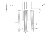
- FIG. 2 is an enlarged cross-sectional view of the vicinity of a fluid inlet in a laminar flow element according to the 1 is a plan view showing the shape of a sheet constituting a laminar flow element according to an embodiment of the present invention.
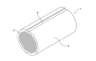
- FIG. 1 is a perspective view showing the appearance of a laminar flow element according to an embodiment of the present invention.
- 1 is a cross-sectional view showing an example of the configuration of a thermal flow sensor incorporating a laminar flow element. 1 is a graph showing the relationship between a reference flow rate and a measured flow rate of nitrogen gas flowing through a laminar flow element.
- FIG. 1 is a graph showing the linearity of a laminar flow element.
- 10 is a plan view showing the shape of a sheet constituting a laminar flow element according to Comparative Example 1.
- FIG. 2 is a perspective view showing the appearance of a laminar flow element according to Comparative Example 1.
- FIG. 11 is a perspective view showing the appearance of a laminar flow element according to Comparative Example 2.
- the present invention is a laminar flow element having multiple flow paths each having an inlet that is an opening on the side where the fluid flows in and an outlet that is an opening on the side where the fluid flows out, in which the shape of each flow path in any cross section of the laminar flow element taken along any plane perpendicular to the flow direction from the inlet to the outlet of the flow path is approximately rectangular, the aspect ratio a/b, where a is the length of the long side of the approximately rectangle and b is the length of the short side, is 5.0 or greater, and the multiple flow paths are arranged so that the long sides of the approximately rectangle are parallel to each other.
- the laminar flow element according to the present invention will be described below with reference to the drawings.
- FIG. 1 is a perspective view showing an example of the shape of the flow paths of a laminar flow element according to the present invention.
- FIG. 1 is a diagram for explaining the shapes and relative positions of multiple flow paths of a laminar flow element, and it should be noted that the multiple flow paths contained in the laminar flow element according to the present invention cannot actually be seen with the naked eye as shown in FIG. 1.
- FIG. 1 shows three flow paths 2 of the laminar flow element 1, the number of flow paths of the laminar flow element need only be multiple and is not limited to three. All three flow paths 2 shown in FIG. 1 have the same shape, but in the present invention, the shapes of the multiple flow paths do not necessarily have to be the same.
- the laminar flow element according to the present invention has a plurality of flow paths each having an inlet, which is an opening on the side where the fluid flows in, and an outlet, which is an opening on the side where the fluid flows out.
- the shape of the flow path in an arbitrary cross section of the laminar flow element taken along an arbitrary plane perpendicular to the flow direction, which is the direction from the inlet to the outlet of the flow path, is approximately rectangular.
- the long arrow with the symbol f indicates the direction in which the fluid flows from the inlet to the outlet of the flow path, i.e., the flow direction.
- the shape of the flow path 2 in any plane perpendicular to the flow direction f in the flow path 2, i.e., in any cross section, is approximately rectangular with a long side length a and a short side length b.
- the long side length a and the short side length b may be the same for all the flow paths, or may be different for each flow path.
- One flow path 2 is composed of two main walls 2a, which are walls including the long sides, and two side walls 2b, which are walls including the short sides. The fluid flows in the flow direction f in the flow path 2, which is the space surrounded by these four walls.
- the three short arrows and the symbols attached to the arrows in Figure 1 respectively represent the directions of the x-axis, y-axis, and z-axis of the Cartesian coordinate system.
- the direction of the x-axis coincides with the direction of the normal to the short side of the approximate rectangle.
- the direction of the y-axis coincides with the direction of the normal to the long side of the approximate rectangle.
- the direction of the z-axis coincides with the flow direction f.
- the aspect ratio a/b is 5.0 or more when the length of the long side in the cross section is a and the length of the short side is b.
- the aspect ratio a/b may be the same for all flow paths 2 or may be different for each flow path, but in either case, the aspect ratio value in all flow paths 2 must be 5.0 or more.
- the aspect ratio is 5.0 or more
- the ratio of the area of the side wall 2b including the short side to the area of the main wall 2a, which is the wall including the long side in the arbitrary cross section, is 20 percent or less.
- a shape factor such as the length b of the short side is called the "characteristic length" of the flow channel shape.
- the characteristic length of the flow channel 2 whose cross section is roughly rectangular as shown in Figure 1 is the length b of the short side.
- the characteristic length of a flow channel whose cross section is, for example, circular is the diameter of the circle.
- the shape of the flow path in the above-mentioned arbitrary cross section is, in principle, a rectangle with all four sides being straight, but it may also be a so-called "slit-like" shape with a roughly constant width and a predetermined length.
- the corners of this rectangle do not necessarily have to be right angles, and the corners of the rectangle may be, for example, a part of the circumference (arc) or a short straight line that forms an angle of 45 degrees with the sides of the rectangle.
- “approximately rectangular” includes such shapes in which the corners are not right angles.
- the corners of the rectangle By forming the corners of the rectangle not at right angles but at parts of the circumference or short straight lines, it is possible to obtain advantages such as suppressing the generation of turbulence at the corners, making it easier to process the flow path, and improving the mechanical strength of the flow path.
- the long side of the rectangle i.e., the part corresponding to the main wall
- the short side of the rectangle i.e., the part corresponding to the side wall
- “approximately rectangular” does not refer to a rectangle in the narrow sense, but rather to a rectangle in the broad sense, including a wide variety of variations that can be considered roughly rectangular as described above.
- the length of the short side shall be read as "the maximum dimension of the flow channel in the direction of the short side.”
- the length of the long side shall be read as "the maximum dimension of the flow channel in the direction of the long side.”
- the aspect ratio a/b shall be determined using the values of a and b obtained by reading them as described above.
- a plurality of flow paths are arranged so that the long sides of the approximately rectangular shape of the flow paths in any cross section are parallel to each other.
- the three flow paths 2 are arranged so that the long sides are parallel to each other in any cross section.
- the normals of the main walls 2a including the long sides all coincide with the y-axis direction, which is the vertical direction in FIG. 1.
- the short sides of the approximately rectangular shape of one flow path 2 do not face the short sides of other flow paths 2 (i.e., there are no adjacent flow paths 2 in the x-axis direction), but the long sides of the approximately rectangular shape of one flow path 2 face the long sides of other flow paths 2, and the three flow paths 2 are arranged so as to overlap closely in the y-axis direction.
- Figure 2 is a schematic diagram showing an enlarged view of the fluid inlet of a laminar flow element according to the present invention.
- the directions of the x-, y-, and z-axes of a Cartesian coordinate system are represented by arrows and symbols attached to the arrows in Figure 2.
- the direction of the x-axis is perpendicular to the plane of the paper in Figure 2
- the direction of the x-axis is represented by a small circle.
- the six long arrows indicate the direction in which the fluid flows.
- the laminar flow element according to the present invention there is less turbulence in the flow of the fluid at the inlet and outlet compared to the laminar flow element according to the prior art, which is composed of circular flow paths with an aspect ratio equal to 1.0, for example.
- the fluid flow inside the laminar flow element forms a laminar flow.
- the fluid has not yet become fully laminar.
- the flow is also significantly turbulent in the section where the fluid is released from the outlet of the laminar flow element into the downstream flow path (the section immediately after flow-out).
- the fluid flow becomes turbulent rather than laminar.
- the area indicated by the symbol t in Figure 2 is an example of such a transition section. If the proportion of the transition section in the entire flow sensor becomes large, it is thought that the flow division ratio will change depending on the flow rate, and the relationship between the flow rate and the pressure drop will no longer be linear.
- the laminar flow element of the present invention multiple flow paths are arranged so that the change in the direction of fluid flow is smaller when the fluid branches at the inlet and when the fluid joins at the outlet, compared to laminar flow elements of conventional technology.
- the proportion of the transition section in the entire flow sensor incorporating the laminar flow element of the present invention is kept small, making it possible to realize a flow sensor with little change in the flow division ratio and excellent linearity.
- the distance d between two adjacent flow paths 2 is shorter than the length b of the short side.
- the first effect is that more flow paths 2 can be provided in a laminar flow element 1 of limited size, so that the flow rate of fluid that can be passed through the laminar flow element 1 can be increased.
- the second effect is that the distance traveled by the fluid when it branches at the inlet of the laminar flow element 1 and the distance traveled by the fluid when it joins at the outlet are shortened, so that turbulence of the fluid in the transition section is suppressed.
- the direction in which it changes course is the y-axis direction of the figure, and the maximum distance is d/2.
- the distance d is made too short, it will not be possible to maintain the strength required to maintain the shape of the main wall 2a, so there is a lower limit to the distance d.
- the lower limit to the distance d can be determined as appropriate taking into account the size of the laminar flow element 1, the material constituting the laminar flow element 1, the manufacturing method, etc.
- the length b of the short side and the thickness d of the main wall 2a are equal for all flow paths 2.
- the length a of the long side does not necessarily have to be equal.
- the length b of the short side, the length c of the flow channel 2 along the flow direction, and the thickness d of the main wall 2a are all equal for all flow channels 2. More preferably, as shown in Figures 1 and 2, the positions on the z-axis of the inlets and outlets of the flow channels 2 for all flow channels are located on the same plane perpendicular to the flow direction. In this case, the positions of the transition sections t in the direction f of fluid flow in the laminar flow element 1 are concentrated at two points, the inlet and the outlet. This maximizes the proportion of the sections in which the fluid flow in all flow channels 2 is laminar in the entire laminar flow element 1, making it possible to realize a more compact laminar flow element.
- the proportion of the multiple flow paths in an arbitrary cross section is 40 percent or more.
- the arbitrary cross section includes the members constituting the walls (including the main walls and side walls) that define the flow paths and all of the flow paths.
- the part that includes the walls that define the flow paths and all of the flow paths is referred to as the "main body”.
- the part surrounded by the outer edge corresponds to this "main body”.
- a more preferable proportion is 45 percent or more. Note that if the proportion s/S of the multiple flow paths in an arbitrary cross section is excessively increased, the proportion of the walls (including the main walls and side walls) that define the flow paths will be excessively reduced, and the strength required to maintain the shape will not be maintained. Therefore, there is an upper limit to s/S, but the specific upper limit of s/S varies depending on, for example, the size of the laminar flow element 1, the material that constitutes the laminar flow element 1, and the manufacturing method.
- the laminar flow element has a "minimum dimension" that is the dimension of the smallest part of the outer shape of the laminar flow element, which is 20 mm or less.
- minimum dimension is the dimension of the smallest part of the outer shape of the laminar flow element, which is 20 mm or less.
- minimum dimension can be said to be the smallest dimension of the dimensions of the body of the laminar flow element measured in various directions. For example, if the dimension of the body in the z-axis direction along the flow path of the laminar flow element is 30 mm, and the dimension of the body in the x-axis or y-axis direction perpendicular to the flow path is 20 mm, the minimum dimension of the body is 20 mm.
- the proportion of the transition section is kept small compared to the laminar flow element of the prior art, so a flow sensor with little change in the flow ratio and excellent linearity can be realized.
- the minimum dimension which is the dimension of the thinnest part of the outer shape of the laminar flow element, is 20 mm or less, it is possible to suppress the deterioration of the linearity of the flow sensor.
- a more preferable minimum dimension of the main body of the laminar flow element is 15 mm or less, and an even more preferable minimum dimension is 10 mm or less.
- the shape of the outer edge of any cross section i.e., the shape of the main body of the laminar flow element in a cross section perpendicular to the flow direction, is a circle.
- the shape of the outer edge of any cross section is a circle, the fluid velocity distribution is fast at the center of the circle and relatively slow in parts away from the center of the circle.
- the shape of the outer edge of any cross section is not a circle, differences in the distribution of distance from the center of the cross section occur around the center of the cross section, resulting in large differences in fluid velocity due to differences in position in the cross section of the main body of the laminar flow element, causing overall turbulence in the fluid flow.
- the shape of the outer edge of any cross section is a circle, such a risk is reduced.
- the short side of the approximately rectangular flow path in any cross section is an arc shape that is convex outward from the approximately rectangular shape.
- the short side being an arc shape means that there is a smooth transition between the side wall and the main wall, rather than the side wall being flat and forming a right-angled corner with the main wall.
- the transition may be formed by a part of the circumference (arc) in any cross section, or may be formed by a narrow flat surface.
- a preferred embodiment of the laminar flow element is constructed by stacking a plurality of thin metal plates in the thickness direction. That is, the laminar flow element is not constructed by a block-shaped member in which a space that serves as a flow path is formed, but by a plurality of thin metal plates stacked in the thickness direction. Such a laminar flow element can be constructed, for example, by drilling a space that serves as a flow path in a block-shaped laminate composed of a plurality of thin metal plates stacked in the flow direction.
- a more preferred embodiment of the laminar flow element is constructed by stacking a plurality of thin metal plates in the thickness direction, in which holes having the shape of a flow path in an arbitrary cross section are pre-formed.
- a method for manufacturing the laminar flow element according to the present invention for example, a method of forming a plurality of flow paths by drilling holes in a cylindrical member made of a metal or alloy or a block-shaped laminate composed of a plurality of thin metal plates stacked in the thickness direction as described above can be considered.
- the minimum dimension of the main body of the laminar flow element is 20 mm or less, such precise drilling requires skill.
- Another method for manufacturing the laminar flow element of the present invention can be to fix multiple plate-shaped partitions parallel to each other on the inner diameter side of a cylindrical member made of metal or alloy. In this case, however, assembly requires skill, and even if assembled, it is not easy to ensure the dimensional precision required for a laminar flow element.
- the laminar flow element of the present invention can be easily manufactured by, for example, manufacturing a large number of thin plates, in which holes having the same cross-sectional shape as the flow path are pre-formed by photolithography and etching, and stacking these thin plates to the required thickness. Moreover, this manufacturing method does not require skill in precision machining or assembly work.
- the present invention is an invention of a flow sensor including a laminar flow element according to the present invention.
- the flow sensor can have a larger rated flow rate and improve the linearity of the output signal compared to a flow sensor of comparable size according to the prior art.
- the flow sensor according to the present invention may be any type of flow sensor that includes a laminar flow element.
- the flow sensor according to the present invention may be, for example, either a thermal flow sensor or a differential pressure flow sensor, or may be a flow sensor that includes a laminar flow element of another type.
- the present invention is an invention of a mass flow controller equipped with a flow sensor according to the present invention.
- the mass flow controller can have a larger rated flow rate and can improve the accuracy of flow control compared to a mass flow controller according to the prior art of a comparable size.
- Example> A stainless steel plate with a thickness of 0.10 mm was prepared. After forming a resist pattern shown in Fig. 3 on both sides of the stainless steel plate using photolithography, an etching solution was sprayed onto the stainless steel plate to corrode and dissolve the portions that would become the approximately rectangular flow paths 2 and the unnecessary portions outside the periphery, and the portions were removed. The resist was then washed and peeled off to produce 150 stainless steel sheets with a circular periphery (outline) as shown in Fig. 3. The 13 flow paths 2 shown in Fig. 3 represent the outlines of holes opened in the stainless steel plate by etching.
- the diameter of the sheet was 8.0 mm
- the length b of the short side of the flow path 2 was 0.32 mm
- the minimum value of the length a of the long side was 2.82 mm (aspect ratio 8.8)
- the maximum value was 6.82 mm (aspect ratio 21.3)
- the distance d between adjacent flow paths 2 was 0.18 mm.
- the length b of the short side is the representative length of the flow path 2.
- the short side of the approximately rectangular shape of the flow path 2 was composed of a semicircle having a diameter of 0.32 mm to be precise.
- the length a of the long side of the approximately rectangular shape is the length interpreted as the maximum dimension of the flow path 2 measured in the direction of the long side, and the aspect ratio is also a numerical value determined using the value a obtained by interpreting it in this way.
- the height of the edge generated on the cut surface by etching from both sides of the stainless steel plate was 5.0 ⁇ m or less.
- the 150 sheets were then stacked in the thickness direction and the sheets were diffusion bonded together by applying a load and heat to produce a laminar flow element 1 having a length of 15 mm, the appearance of which is shown in Figure 4.
- a jig was used to ensure that the positions of the notches 4 of all the sheets were aligned. Note that the lines indicating the boundaries between adjacent sheets have been omitted in Figure 4.
- the completed laminar flow element 1 was incorporated into the bypass flow path of the thermal flow sensor 6 shown in Figure 5.
- the laminar flow element 1 was oriented so that the long side of the approximately rectangular shape of the flow path 2 of the flow path in any cross section was perpendicular to the vertical direction in Figure 5 where the sensor tube 5 of the thermal flow sensor 6 branches.
- a nitrogen gas cylinder and a pressure reducing valve were installed upstream of the thermal flow sensor 6, and the pressure of the nitrogen gas was adjusted to 300 kilopascals using the pressure reducing valve.
- a flow control valve and a differential pressure standard flow meter were installed downstream of the thermal flow sensor 6 in this order, and the atmospheric pressure downstream of the differential pressure standard flow meter was 100 kilopascals.
- thermal flow sensor 6 was calibrated so that the measured flow rate indicated by the thermal flow sensor 6 was 20 standard liters per minute when the reference flow rate of nitrogen gas indicated by the differential pressure standard flow meter was 20 standard liters per minute.
- the flow control valve was opened to supply a fixed amount of nitrogen gas to the thermal flow sensor 6, and the reference flow rate indicated by the differential pressure standard flow meter and the measured flow rate indicated by the thermal flow sensor 6 were measured simultaneously.
- the flow rate of the nitrogen gas was adjusted using the flow control valve, and the maximum flow rate was set to 20 standard liters per minute, which is the rated flow rate of the thermal flow sensor 6.
- FIG. 6 is a graph showing the relationship between the reference flow rate and the measured flow rate of nitrogen gas flowing through the laminar flow element obtained by the above measurement method.
- the horizontal axis of the graph in FIG. 6 is the reference flow rate of nitrogen gas indicated by the differential pressure standard flow meter, in standard liters per minute.
- the vertical axis of the graph is the measured flow rate of nitrogen gas indicated by the thermal flow sensor 6, also in standard liters per minute.
- the plots indicated by circles are data from the thermal flow sensor 6 using the laminar flow element 1 according to the present invention.
- the dotted line in the graph indicates a reference straight line connecting the origin of the graph and the plot of the maximum flow rate.
- the measured flow rate of the thermal flow sensor 6 using the laminar flow element 1 according to the present invention closely matches the reference flow rate indicated by the standard differential pressure flow meter, and it can be seen that the linearity of this thermal flow sensor 6 is good.
- FIG. 7 is a graph showing the difference between the measured flow rate and the reference flow rate of the thermal flow sensor 6 in FIG. 6, divided by the maximum flow rate of 20 standard liters per minute, expressed as a percentage. In this specification, this value is referred to as "linearity.” As in FIG. 6, the plots indicated by circles are data for the thermal flow sensor 6 using the laminar flow element 1 of the present invention. As mentioned above, the thermal flow sensor 6 is calibrated so that the difference between the measured flow rate and the reference flow rate is zero at 20 standard liters per minute, so the linearity value is zero at 20 standard liters per minute.
- the linearity of the thermal flow sensor 6 using the laminar flow element 1 according to the present invention remains below zero when the flow rate is in the range of 1 standard liter per minute to 14 standard liters per minute, with a minimum value of -1.3 percent.
- a resist having the pattern shown in Fig. 8 was formed on both sides of the same stainless steel plate as the stainless steel plate prepared in the examples by photolithography, and then an etching solution was sprayed onto the plate to corrode and dissolve the portion that would become the circular flow path 2' and the unnecessary portion outside the periphery, thereby removing the portion. The resist was then washed and peeled off, thereby producing 150 stainless steel sheets each having a circular periphery (outline) as shown in Fig. 8.
- the diameter of the sheet was 8.0 mm
- the diameter b' of the circle in the cross section of the flow path 2' was 0.60 mm
- the number of holes in the flow path 2' was 69
- the minimum value of the distance d' between adjacent flow paths 2' was 0.10 mm and the maximum value was 0.39 mm.
- This diameter b' of the circle was the representative length of the flow path 2'.
- the height of the edges generated on the cut surface by etching from both sides of the stainless steel plate was 5.0 ⁇ m or less.
- the 150 sheets were then stacked in the thickness direction and the sheets were diffusion bonded together by applying a load and heat to produce a laminar flow element 1' having a length of 15 mm, the appearance of which is shown in Figure 9.
- a jig was used to ensure that the positions of the notches 4 of all the sheets were aligned.
- the laminar flow element 1' of Comparative Example 1 was designed so that the pressure loss was approximately the same as that of the laminar flow element 1 of the Example.
- the linearity of the thermal flow sensor 6 using the laminar flow element 1' of Comparative Example 1 was greater than zero over a wide range of flow rates, with a maximum value of 7.3 percent.
- the linearity of the thermal flow sensor 6 using the laminar flow element 1'' of Comparative Example 2 was greater than zero over a wide range of flow rates, with a maximum value of 7.5 percent.
- Table 1 shows the specifications and linearity evaluation results of the laminar flow elements for the embodiment and two comparative examples.
- the flow channel area ratio and wall area were calculated assuming that the cross-sectional shape of the flow channel is rectangular.
- the laminar flow element of the Example has a larger flow path area ratio (i.e., the proportion s/S of multiple flow paths in an arbitrary cross section). This is because the cross-sectional shape of the flow paths in the Example is approximately rectangular, and the distance between the flow paths (i.e., the thickness of the main wall) d is short, resulting in multiple flow paths 2 being densely stacked.
- the linearity of the laminar flow element of the Example was superior to that of the laminar flow element of Comparative Example 1. Considering that the sensor tubes of the thermal flow sensors of the Example and Comparative Example 1 are the same and that the linearity was superior in the Example, it is believed that this difference in linearity is due to the difference in the stability of the flow division ratio of the laminar flow element. In other words, it is believed that the flow division ratio changed very little with flow rate because there was less turbulence in the fluid flow at the inlet and outlet of the laminar flow element 1 of the present invention compared to the laminar flow element 1' of the prior art.
- the laminar flow element according to the embodiment of the present invention does not require skilled manufacturing, and that a thermal flow sensor using this laminar flow element can obtain excellent linearity in the measured flow rate over a wide range from a state where the flow rate is zero to a large flow rate of 20 standard liters per minute.
Landscapes
- Physics & Mathematics (AREA)
- Fluid Mechanics (AREA)
- General Physics & Mathematics (AREA)
- Measuring Volume Flow (AREA)
Priority Applications (3)
| Application Number | Priority Date | Filing Date | Title |
|---|---|---|---|
| CN202480009360.XA CN120615161A (zh) | 2023-01-31 | 2024-01-26 | 层流元件、流量传感器和质量流量控制器 |
| KR1020257025232A KR20250139292A (ko) | 2023-01-31 | 2024-01-26 | 층류 소자, 유량 센서 및 매스 플로 컨트롤러 |
| JP2024574850A JPWO2024162194A1 (https=) | 2023-01-31 | 2024-01-26 |
Applications Claiming Priority (2)
| Application Number | Priority Date | Filing Date | Title |
|---|---|---|---|
| JP2023-012937 | 2023-01-31 | ||
| JP2023012937 | 2023-01-31 |
Publications (1)
| Publication Number | Publication Date |
|---|---|
| WO2024162194A1 true WO2024162194A1 (ja) | 2024-08-08 |
Family
ID=92146709
Family Applications (1)
| Application Number | Title | Priority Date | Filing Date |
|---|---|---|---|
| PCT/JP2024/002357 Ceased WO2024162194A1 (ja) | 2023-01-31 | 2024-01-26 | 層流素子、流量センサ及びマスフローコントローラ |
Country Status (4)
| Country | Link |
|---|---|
| JP (1) | JPWO2024162194A1 (https=) |
| KR (1) | KR20250139292A (https=) |
| CN (1) | CN120615161A (https=) |
| WO (1) | WO2024162194A1 (https=) |
Citations (8)
| Publication number | Priority date | Publication date | Assignee | Title |
|---|---|---|---|---|
| JPH0518799A (ja) * | 1991-07-11 | 1993-01-26 | Stec Kk | 層流素子およびその製造方法 |
| JPH11101673A (ja) * | 1997-09-27 | 1999-04-13 | Stec Kk | 層流素子 |
| JP2003185477A (ja) * | 2001-12-21 | 2003-07-03 | Yazaki Corp | 流量計 |
| JP2003344135A (ja) * | 2003-05-19 | 2003-12-03 | Ckd Corp | 熱式流量計 |
| US20140352453A1 (en) * | 2013-06-04 | 2014-12-04 | Hydrometer Gmbh | Flowmeter |
| CN107218981A (zh) * | 2017-05-16 | 2017-09-29 | 湖北锐意自控系统有限公司 | 一种基于超声波旁流原理的气体流量测量装置及方法 |
| CN109341788A (zh) * | 2018-12-24 | 2019-02-15 | 西北工业大学 | 小型层流元件 |
| WO2021100539A1 (ja) * | 2019-11-19 | 2021-05-27 | パナソニックIpマネジメント株式会社 | 超音波流量計 |
Family Cites Families (6)
| Publication number | Priority date | Publication date | Assignee | Title |
|---|---|---|---|---|
| US4949755A (en) | 1986-11-21 | 1990-08-21 | Allied-Signal Inc. | Fluidic volumetric fluid flow meter |
| JPS6440300A (en) | 1987-08-07 | 1989-02-10 | Mitsubishi Heavy Ind Ltd | Liquid-metal jet cutting method |
| JP4684387B2 (ja) | 2000-05-26 | 2011-05-18 | 株式会社堀場エステック | 流量検出機構及び流量検出機構に用いられる抵抗物の製造方法 |
| CN101218019B (zh) | 2005-04-08 | 2011-11-09 | 维罗西股份有限公司 | 通过多个平行的连接通道流向/来自歧管的流体控制 |
| JP5794884B2 (ja) | 2011-10-05 | 2015-10-14 | 株式会社堀場エステック | 流体制御システム |
| JP6819863B2 (ja) | 2016-04-07 | 2021-01-27 | 日立金属株式会社 | バイパスユニット、流量計用ベース、流量制御装置用ベース、流量計、及び流量制御装置 |
-
2024
- 2024-01-26 JP JP2024574850A patent/JPWO2024162194A1/ja active Pending
- 2024-01-26 WO PCT/JP2024/002357 patent/WO2024162194A1/ja not_active Ceased
- 2024-01-26 KR KR1020257025232A patent/KR20250139292A/ko active Pending
- 2024-01-26 CN CN202480009360.XA patent/CN120615161A/zh active Pending
Patent Citations (8)
| Publication number | Priority date | Publication date | Assignee | Title |
|---|---|---|---|---|
| JPH0518799A (ja) * | 1991-07-11 | 1993-01-26 | Stec Kk | 層流素子およびその製造方法 |
| JPH11101673A (ja) * | 1997-09-27 | 1999-04-13 | Stec Kk | 層流素子 |
| JP2003185477A (ja) * | 2001-12-21 | 2003-07-03 | Yazaki Corp | 流量計 |
| JP2003344135A (ja) * | 2003-05-19 | 2003-12-03 | Ckd Corp | 熱式流量計 |
| US20140352453A1 (en) * | 2013-06-04 | 2014-12-04 | Hydrometer Gmbh | Flowmeter |
| CN107218981A (zh) * | 2017-05-16 | 2017-09-29 | 湖北锐意自控系统有限公司 | 一种基于超声波旁流原理的气体流量测量装置及方法 |
| CN109341788A (zh) * | 2018-12-24 | 2019-02-15 | 西北工业大学 | 小型层流元件 |
| WO2021100539A1 (ja) * | 2019-11-19 | 2021-05-27 | パナソニックIpマネジメント株式会社 | 超音波流量計 |
Also Published As
| Publication number | Publication date |
|---|---|
| KR20250139292A (ko) | 2025-09-23 |
| CN120615161A (zh) | 2025-09-09 |
| JPWO2024162194A1 (https=) | 2024-08-08 |
Similar Documents
| Publication | Publication Date | Title |
|---|---|---|
| US6886401B2 (en) | Thermal flow sensor having sensor and bypass passages | |
| CN101900588B (zh) | 包括锥形流动通路的流量传感设备 | |
| EP3118589B1 (en) | Flow sensor assembly with bypass channel | |
| US20050081620A1 (en) | Thermal flowmeter | |
| JPWO2013008445A1 (ja) | 超音波流量計 | |
| TW201736746A (zh) | 節流單元、設有該節流單元的靜壓軸承裝置及附設溝槽的塊體之製造方法 | |
| WO2024162194A1 (ja) | 層流素子、流量センサ及びマスフローコントローラ | |
| CN113155207A (zh) | 差压式流量计 | |
| TW202029381A (zh) | 用於非接觸支持平台之埠口配置技術 | |
| JP6306286B2 (ja) | 流量制御用のオリフィスプレート及びこれを用いた圧力式流量制御装置 | |
| US20220196336A1 (en) | Heat exchanger | |
| JP2014215782A5 (https=) | ||
| CN118838430A (zh) | 流体调节装置和质量流量控制器 | |
| JP3871566B2 (ja) | 熱式流量計 | |
| CN221406374U (zh) | 一种微通道层流元件及气体质量流量控制器 | |
| JP3637050B2 (ja) | 熱式流量計 | |
| US10982985B2 (en) | High flow tubular bypass | |
| JP3715920B2 (ja) | 熱式流量計 | |
| WO2023132184A1 (en) | Flow restrictor for fluid flow device | |
| US20260056042A1 (en) | Laminar flow element | |
| CN222363223U (zh) | 一种整流管及整流格栅 | |
| JP5364059B2 (ja) | 熱式流量計 | |
| JP3645900B2 (ja) | 熱式流量計 | |
| JPWO2024162194A5 (https=) | ||
| JP7611751B2 (ja) | 流量計 |
Legal Events
| Date | Code | Title | Description |
|---|---|---|---|
| 121 | Ep: the epo has been informed by wipo that ep was designated in this application |
Ref document number: 24750143 Country of ref document: EP Kind code of ref document: A1 |
|
| ENP | Entry into the national phase |
Ref document number: 2024574850 Country of ref document: JP Kind code of ref document: A |
|
| WWE | Wipo information: entry into national phase |
Ref document number: 2024574850 Country of ref document: JP |
|
| WWE | Wipo information: entry into national phase |
Ref document number: 202480009360.X Country of ref document: CN |
|
| ENP | Entry into the national phase |
Ref document number: 1020257025232 Country of ref document: KR Free format text: ST27 STATUS EVENT CODE: A-0-1-A10-A15-NAP-PA0105 (AS PROVIDED BY THE NATIONAL OFFICE) |
|
| NENP | Non-entry into the national phase |
Ref country code: DE |
|
| WWP | Wipo information: published in national office |
Ref document number: 202480009360.X Country of ref document: CN |
|
| 122 | Ep: pct application non-entry in european phase |
Ref document number: 24750143 Country of ref document: EP Kind code of ref document: A1 |