WO2024162076A1 - 採血装置 - Google Patents
採血装置 Download PDFInfo
- Publication number
- WO2024162076A1 WO2024162076A1 PCT/JP2024/001695 JP2024001695W WO2024162076A1 WO 2024162076 A1 WO2024162076 A1 WO 2024162076A1 JP 2024001695 W JP2024001695 W JP 2024001695W WO 2024162076 A1 WO2024162076 A1 WO 2024162076A1
- Authority
- WO
- WIPO (PCT)
- Prior art keywords
- blood collection
- collection tube
- blood
- protrusion
- turntable
- Prior art date
- Legal status (The legal status is an assumption and is not a legal conclusion. Google has not performed a legal analysis and makes no representation as to the accuracy of the status listed.)
- Ceased
Links
Images








Classifications
-
- A—HUMAN NECESSITIES
- A61—MEDICAL OR VETERINARY SCIENCE; HYGIENE
- A61B—DIAGNOSIS; SURGERY; IDENTIFICATION
- A61B5/00—Measuring for diagnostic purposes; Identification of persons
- A61B5/15—Devices for taking samples of blood
- A61B5/150007—Details
- A61B5/150015—Source of blood
- A61B5/150022—Source of blood for capillary blood or interstitial fluid
-
- A—HUMAN NECESSITIES
- A61—MEDICAL OR VETERINARY SCIENCE; HYGIENE
- A61B—DIAGNOSIS; SURGERY; IDENTIFICATION
- A61B5/00—Measuring for diagnostic purposes; Identification of persons
- A61B5/15—Devices for taking samples of blood
- A61B5/150007—Details
- A61B5/150053—Details for enhanced collection of blood or interstitial fluid at the sample site, e.g. by applying compression, heat, vibration, ultrasound, suction or vacuum to tissue; for reduction of pain or discomfort; Skin piercing elements, e.g. blades, needles, lancets or canulas, with adjustable piercing speed
- A61B5/150061—Means for enhancing collection
- A61B5/150068—Means for enhancing collection by tissue compression, e.g. with specially designed surface of device contacting the skin area to be pierced
-
- A—HUMAN NECESSITIES
- A61—MEDICAL OR VETERINARY SCIENCE; HYGIENE
- A61B—DIAGNOSIS; SURGERY; IDENTIFICATION
- A61B5/00—Measuring for diagnostic purposes; Identification of persons
- A61B5/15—Devices for taking samples of blood
- A61B5/150007—Details
- A61B5/150053—Details for enhanced collection of blood or interstitial fluid at the sample site, e.g. by applying compression, heat, vibration, ultrasound, suction or vacuum to tissue; for reduction of pain or discomfort; Skin piercing elements, e.g. blades, needles, lancets or canulas, with adjustable piercing speed
- A61B5/150106—Means for reducing pain or discomfort applied before puncturing; desensitising the skin at the location where body is to be pierced
- A61B5/150114—Means for reducing pain or discomfort applied before puncturing; desensitising the skin at the location where body is to be pierced by tissue compression, e.g. with specially designed surface of device contacting the skin area to be pierced
-
- A—HUMAN NECESSITIES
- A61—MEDICAL OR VETERINARY SCIENCE; HYGIENE
- A61B—DIAGNOSIS; SURGERY; IDENTIFICATION
- A61B5/00—Measuring for diagnostic purposes; Identification of persons
- A61B5/15—Devices for taking samples of blood
- A61B5/150007—Details
- A61B5/150343—Collection vessels for collecting blood samples from the skin surface, e.g. test tubes, cuvettes
-
- A—HUMAN NECESSITIES
- A61—MEDICAL OR VETERINARY SCIENCE; HYGIENE
- A61B—DIAGNOSIS; SURGERY; IDENTIFICATION
- A61B5/00—Measuring for diagnostic purposes; Identification of persons
- A61B5/15—Devices for taking samples of blood
- A61B5/150007—Details
- A61B5/150374—Details of piercing elements or protective means for preventing accidental injuries by such piercing elements
- A61B5/150381—Design of piercing elements
- A61B5/150412—Pointed piercing elements, e.g. needles, lancets for piercing the skin
-
- A—HUMAN NECESSITIES
- A61—MEDICAL OR VETERINARY SCIENCE; HYGIENE
- A61B—DIAGNOSIS; SURGERY; IDENTIFICATION
- A61B5/00—Measuring for diagnostic purposes; Identification of persons
- A61B5/15—Devices for taking samples of blood
- A61B5/150007—Details
- A61B5/150374—Details of piercing elements or protective means for preventing accidental injuries by such piercing elements
- A61B5/150381—Design of piercing elements
- A61B5/150503—Single-ended needles
-
- A—HUMAN NECESSITIES
- A61—MEDICAL OR VETERINARY SCIENCE; HYGIENE
- A61B—DIAGNOSIS; SURGERY; IDENTIFICATION
- A61B5/00—Measuring for diagnostic purposes; Identification of persons
- A61B5/15—Devices for taking samples of blood
- A61B5/150007—Details
- A61B5/150748—Having means for aiding positioning of the piercing device at a location where the body is to be pierced
-
- A—HUMAN NECESSITIES
- A61—MEDICAL OR VETERINARY SCIENCE; HYGIENE
- A61B—DIAGNOSIS; SURGERY; IDENTIFICATION
- A61B5/00—Measuring for diagnostic purposes; Identification of persons
- A61B5/15—Devices for taking samples of blood
- A61B5/150007—Details
- A61B5/150755—Blood sample preparation for further analysis, e.g. by separating blood components or by mixing
-
- A—HUMAN NECESSITIES
- A61—MEDICAL OR VETERINARY SCIENCE; HYGIENE
- A61B—DIAGNOSIS; SURGERY; IDENTIFICATION
- A61B5/00—Measuring for diagnostic purposes; Identification of persons
- A61B5/15—Devices for taking samples of blood
- A61B5/151—Devices specially adapted for taking samples of capillary blood, e.g. by lancets, needles or blades
-
- B—PERFORMING OPERATIONS; TRANSPORTING
- B01—PHYSICAL OR CHEMICAL PROCESSES OR APPARATUS IN GENERAL
- B01L—CHEMICAL OR PHYSICAL LABORATORY APPARATUS FOR GENERAL USE
- B01L3/00—Containers or dishes for laboratory use, e.g. laboratory glassware; Droppers
- B01L3/50—Containers for the purpose of retaining a material to be analysed, e.g. test tubes
- B01L3/502—Containers for the purpose of retaining a material to be analysed, e.g. test tubes with fluid transport, e.g. in multi-compartment structures
- B01L3/5021—Test tubes specially adapted for centrifugation purposes
Definitions
- the present invention relates to a blood collection device that automatically collects blood from a subject.
- Patent Document 1 discloses a blood collection device to which a blood collection tube module is attached.
- Patent Document 2 discloses a blood collection tube preparation device that is provided with a direction detection means for detecting the orientation of the blood collection tube.
- some blood collection tubes have a protrusion formed on the upper opening.
- the protrusion is formed by part of the circumference of the opening protruding upward.
- the protrusion forms a scoop-like receiving port around the opening.
- This type of protrusion is mainly used in micro blood collection tubes.
- the protrusion functions as a receiving surface for blood when performing delicate operations, and as a receiving surface and guide for tools such as pipettes.
- protrusions can be used to efficiently collect blood from the subject's puncture site into a collection tube.
- the present invention aims to provide a blood collection device that can adjust the orientation of a blood collection tube installed for blood collection around its central axis, thereby reducing the workload involved in blood collection and enabling efficient and stable blood collection into a blood collection tube.
- the blood collection device of the present invention comprises a holder in which a blood collection tube is placed, a blood collection section that collects blood from a subject into the blood collection tube, and a direction adjustment mechanism that adjusts the direction of the blood collection tube in the holder, the blood collection tube having a cylindrical main body with a bottom and an opening at the top, and a protrusion formed by a portion of the opening in the circumferential direction protruding upward, and the direction adjustment mechanism adjusts the direction of the blood collection tube around the central axis so that the position of the protrusion relative to the central axis of the blood collection tube is within a predetermined range.
- the present invention provides a blood collection device that can adjust the orientation of the blood collection tube installed for blood collection around its central axis, reducing the workload involved in blood collection and enabling efficient and stable blood collection into the blood collection tube.
- FIG. 1 is an external view of a blood sampling device according to an embodiment of the present invention.
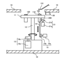
- FIG. 2 is a diagram showing an example of a main part of a blood sampling device according to an embodiment of the present invention.
- FIG. 2 is a diagram showing an example of a blood collection tube that can be used in the blood collection device according to the embodiment of the present invention.
- FIG. 4 is a block diagram showing an example of a configuration related to control of the blood sampling device.
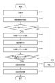
- 13A to 13C are diagrams illustrating a preparatory operation for electrically controlling the orientation of a blood collection tube about its central axis.
- FIG. 4 is a diagram showing an example of the arrangement of a position sensor for detecting the position of a protrusion of a blood collection tube.
- FIG. 4 is a diagram showing an example of the arrangement of a position sensor for detecting the position of a protrusion of a blood collection tube.
- FIG. 4 is a diagram showing an example of the arrangement of a position sensor for detecting the position of a protrusion of a blood collection tube.
- FIG. 4 is a diagram showing an example of the arrangement of a position sensor for detecting the position of a protrusion of a blood collection tube.
- FIG. 2 is a diagram showing an example of a main part of a blood sampling device according to an embodiment of the present invention.
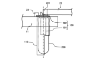
- FIG. 2 is an enlarged view showing the periphery of a blood sampling position of the blood sampling device according to the embodiment of the present invention.
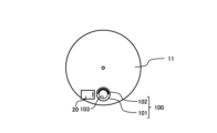
- FIG. 2 is a top view of the area around the blood sampling position of the blood sampling device according to the embodiment of the present invention.
- FIG. 13 is a diagram for explaining a method for mechanically adjusting the orientation of a blood collection tube around its central axis.
- FIG. 13 is a diagram for explaining a method for mechanically adjusting the orientation of a blood collection tube around its central axis.
- FIG. 13 is a diagram for explaining a method for mechanically adjusting the orientation of a blood collection tube around its central axis.
- FIG. 1 is an external view of a blood sampling device according to an embodiment of the present invention.
- FIG. 1 shows a finger blood sampling device that automatically samples blood from the subject's finger.
- the symbol P in FIG. 1 is an enlarged partial view showing the area around the finger placement area of the blood sampling device as viewed from below.
- the blood collection device 1 includes a housing 10, a turntable 11, a number of holders 110 in which blood collection tubes are placed, a number of modules 120, a cuff mechanism 130, a rotation drive mechanism (not shown) that rotates the turntable 11, a lift drive mechanism (not shown) that raises and lowers the holders 110 and modules 120, a pressure adjustment mechanism (not shown) that drives the cuff mechanism 130, and the like.
- the housing 10 is formed from multiple structural materials, decorative panels, etc. Inside the housing 10, a turntable 11, a rotation drive mechanism, an elevation drive mechanism, a pressure adjustment mechanism, etc. are built in. On the top surface of the housing 10, there is a hand placement area where the hand of the person to be blood-collected is placed, and a circular opening adjacent to the hand placement area. The turntable 11 is located below the opening.
- a cuff mechanism 130 and a finger rest area 131 are provided on the opening side of the hand rest area.
- the cuff mechanism 130 is installed above the finger rest area 131 so as to surround the finger 134 of the person to be blood-collected, which is placed on the finger rest area 131.
- a disposable finger rest part 132 is attached to the finger rest area 131.
- a blood collection window 133 which is a through-hole, opens in the center of the finger rest part 132.
- the finger 134 of the person to be blood-collected is placed on the blood collection window 133 of the finger rest part 132.
- the cuff mechanism 130 is a mechanism that tightens around the finger 134 of the person to whom blood is to be drawn.
- a cuff is placed on the finger rest area 131 so as to surround the finger 134 placed thereon.
- the cuff is, for example, in the shape of a flexible bag, and is connected to a valve and a pump via a tube.
- the valve and pump constitute a pressure adjustment mechanism that drives the cuff mechanism 130.
- the tightening pressure on the finger 134 of the person to whom blood is to be drawn is adjusted by controlling the internal pressure of the cuff with the valve and pump.
- the turntable 11 is generally disk-shaped and is supported inside the housing 10 with its main surfaces facing up and down.
- the turntable 11 is provided with a number of portions for supporting the holder 110.
- a number of retaining holes are provided that penetrate the turntable 11 from top to bottom.
- the modules 120 are held in the retaining holes by being inserted from top to bottom.
- the portions and retaining holes that support the holder 110 are regularly spaced apart along the circumferential direction of the turntable 11.
- the holder 110 is where the blood collection tubes are placed, and various types of blood collection tubes, such as blood collection tubes for blood count tests and blood collection tubes for biochemistry and immunological tests, are placed in it. Blood collection tubes of a specified size and outer tubes that contain blood collection tubes can be placed in the holder 110. The outer tubes are used for purposes such as adjusting the size of the object to be placed in relation to the placement location of the blood collection tube.
- the module 120 is detachably attached to the turntable 11.
- the module 120 is formed with a flange-shaped portion whose diameter is larger than the inner diameter of the holding hole of the turntable 11.
- the module 120 is inserted into the holding hole and the flange-shaped portion is supported from below, so that the module 120 is held in a state in which it can be raised and lowered within the holding hole.
- modules 120 can be attached as module 120, such as a module for puncturing, a module for stopping bleeding, etc.
- a puncture device is attached to the module for puncturing.
- the puncture device has a built-in puncture needle (lancet). Gauze or a bandage is attached to the module for stopping bleeding.
- the needle When the lancing device is pressed against the subject's finger, the needle is extended and punctures the subject.
- the gauze is pressed against the puncture site on the subject, absorbing blood that has bled from the puncture site and stopping the bleeding.
- the bandage is pressed against the puncture site on the subject and adheres to seal the puncture site and stop the bleeding.
- the bandage is attached to the module with the adhesive side facing upwards.
- FIG. 2 is a diagram showing an example of a main part of a blood sampling device according to an embodiment of the present invention, and shows an example of a structure around a turntable 11 installed inside the blood sampling device 1.
- a turntable 11 installed inside the blood sampling device 1.
- a rotation drive mechanism 13 is built in below the opening of housing 10.
- Rotation drive mechanism 13, movable support member 14, and elevation drive mechanism 15 are supported at predetermined positions by support members (not shown).
- a shaft 12 is connected to the center of the turntable 11.
- the other end of the shaft 12 is supported for free rotation by a rotation drive mechanism 13.
- the rotation drive mechanism 13 is composed of a motor 13a and a power transmission mechanism 13b.
- the power transmission mechanism 13b connects the output shaft of the motor 13a to the shaft 12 via a specified mechanical mechanism.
- the rotational motion of the motor 13a is transmitted to the shaft 12 by the power transmission mechanism 13b.
- the rotation drive mechanism 13 rotates the turntable 11 using this mechanism.
- the turntable 11 can be rotated in both clockwise and counterclockwise directions by the rotation drive mechanism 13 around a rotation axis passing through the center of the main surface.
- the turntable 11 is controlled to rotate at a predetermined step angle according to the blood collection operation or treatment operation.
- the holder 110 and the module 120 are each transported by the rotation of the turntable 11 to a blood collection position where a finger placement area 131 is formed.
- the puncture needle is inserted by the puncture module, the hemostasis module stops the bleeding using gauze, and the hemostasis module applies a bandage, in that order.
- the subject's finger 134 is compressed by the cuff mechanism 130, and then punctured with the puncture needle by the puncture module. Blood that flows out from the puncture site is collected in a blood collection tube that has been moved to the blood collection position on the turntable 11.
- the movable support member 14 is positioned below the blood collection position.
- the movable support member 14 is supported by a lifting drive mechanism 15 so that it can be raised and lowered freely.
- the lifting drive mechanism 15 is composed of a motor 15a and a power transmission mechanism 15b.
- the power transmission mechanism 15b connects the output shaft of the motor 15a to the movable support member 14 via a specified mechanical mechanism.
- the rotational motion of the motor 15a is converted into vertical linear motion by the power transmission mechanism 15b.
- the lifting drive mechanism 15 raises and lowers the movable support member 14 using this mechanism.
- the holder 110 and the module 120 When the holder 110 and the module 120 are moved to the blood collection position by the rotation of the turntable 11, they are pushed up from below by the rise of the movable support member 14, and pulled down by the fall of the movable support member 14, causing them to move up and down relative to the finger placement area 131. This action causes the blood collection tube to be pressed against the puncture site, the puncture needle to puncture the subject's finger 134, and gauze or a bandage to be pressed against the puncture site.
- FIG. 3 is a diagram showing an example of a blood collection tube that can be used in the blood collection device according to the embodiment of the present invention.
- a blood collection tube for collecting blood from a subject is a blood collection tube 100 having a protrusion 102 formed at the upper opening.
- a blood collection tube 100 having a protrusion 102 as shown in Fig. 3 can be used.
- the blood collection tube 100 shown in FIG. 3 has a cylindrical main body 101 with a bottom and an open top, and a protrusion 102 that protrudes upward.
- An opening 103 is formed in the top of the main body 101.
- the opening 103 has a circular shape when viewed from above the blood collection tube 100, and is connected to the inside of the main body 101.
- the protrusion 102 is provided in the top of the main body 101, and a portion of the circumferential direction of the opening 103 protrudes upward beyond the main body 101.
- the protrusion 102 has a surface that is continuous with the inner peripheral surface of the main body 101, and is curved with the same curvature as the inner peripheral surface of the main body 101.
- the protrusion 102 forms a socket-like scoop around the opening 103.
- the protrusion 102 can function as a receiving surface for receiving blood collected in the blood collection tube 100, or as a receiving surface/guide for an instrument such as a pipette.
- the protrusion 102 faces a predetermined direction when the blood collection tube 100 is moved to the blood collection position by rotation of the turntable 11.
- the blood collection device 1 performs control to adjust the orientation of the blood collection tube 100 around the central axis so that the relative position of the protrusion 102 with respect to the central axis of the blood collection tube 100 (dash line in FIG. 3) falls within a preset range.
- the orientation of the blood collection tube 100 around the central axis By adjusting the orientation of the blood collection tube 100 around the central axis, the position of the protrusion 102 with respect to the central axis of the blood collection tube 100 in the circumferential direction of the opening 103, i.e., the orientation of the protrusion 102 with respect to the central axis, is adjusted.
- the orientation of the blood collection tube 100 around its central axis is adjusted so that the relative position of the protrusion 102 at the blood collection position on the turntable 11 is within a target range.
- the adjustment of the orientation of the blood collection tube 100 around its central axis is performed in a preparation operation that is performed before the start of a blood collection operation.
- the blood collection operation is an operation in which a puncture needle is inserted into the subject to collect blood from the subject into a blood collection tube.
- the orientation of the blood collection tube 100 around its central axis can be adjusted to any orientation.
- the relative position of the protrusion 102 with respect to the central axis of the blood collection tube 100 can be adjusted to be within any target range.
- the target range can be set in advance when using the blood collection device 1.
- the target range can have any range width depending on the width of the protrusion 102, etc.
- the target range of the relative position of the protrusion 102 with respect to the central axis of the blood collection tube 100 can be set as a partially annular region having an approximate shape with an arbitrary arc length along the circumferential direction of the opening 103 of the blood collection tube 100 when viewed from above the blood collection tube 100 that has been moved to the blood collection position on the turntable 11. Control is performed to adjust the orientation of the blood collection tube 100 around the central axis so that both side ends of the protrusion 102 fall within such a region.
- the target range of the relative position of the protrusion 102 with respect to the central axis of the blood collection tube 100 is preferably set to a half region located closer to the center of the turntable 11 than the central axis of the blood collection tube 100, or a half region located outside the turntable 11 than the central axis of the blood collection tube 100. In other words, it is preferably set to a half region closer to the puncture site of the subject with respect to the central axis of the blood collection tube 100, or a half region farther from the puncture site of the subject with respect to the central axis of the blood collection tube 100.
- the blood collection device 1 can have a function of tilting the blood collection tube that has been moved to the blood collection position along the radial direction of the turntable 11.
- the direction of the protrusion 102 at the blood collection position is in the forward or reverse direction relative to the tilt direction of the blood collection tube, from the viewpoint of arranging it in a receptacle shape. If the target range is set to a half region located toward the center or outside of the turntable 11, it becomes possible to efficiently collect blood by having it flow along the protrusion 102.
- the blood collection tube 100 is placed in the holder 110.
- the blood collection tube 100 is placed in the holder 110 while being housed in the outer tube 200.
- the relative position of the protrusion 102 with respect to the central axis of the blood collection tube 100 can be adjusted by changing the orientation around the central axis of the outer tube 200.
- the holder 110 is configured with an opening on the outer portion of the outer periphery.
- the holder 110 is configured in a structure that opens the side of the object to be placed toward the outside. With such a structure, the orientation of the object placed in the holder 110 can be adjusted from the outside.
- the holder 110 can be configured in an appropriate structure depending on the method for adjusting the orientation around the central axis of the blood collection tube 100, etc.
- a position sensor 20 is installed to the side of the blood collection position.
- the position sensor 20 is a sensor for detecting the position of the protrusion 102 of the blood collection tube 100.
- the position sensor 20 detects the position of the protrusion 102, for example, the position of the side end of the protrusion 102, for the blood collection tube 100 that has been moved to the blood collection position on the turntable 11. Based on the detection result by the position sensor 20, the orientation of the blood collection tube 100 around its central axis can be controlled.
- the position sensor 20 may be an optical sensor, a camera sensor, or the like.
- the position sensor 20 may be installed at a fixed point, such as to the side of the protrusion 102, so that the position sensor 20 can monitor the target range of the relative position of the protrusion 102 with respect to the central axis of the blood collection tube 100 at the blood collection position on the turntable 11.
- one sensor or multiple sensors may be installed.
- the optical sensor is composed of a light source (light projecting unit) that irradiates laser light or the like, and an optical sensor (light receiving unit) that detects reflected light and scattered light from the irradiated light.
- the position of the side end of the protrusion 102 can be detected by irradiating light such as laser light to an area within a target range of the height of the protrusion 102 at the blood collection position, which is the relative position of the protrusion 102 to the central axis of the blood collection tube 100, and measuring the light intensity of the reflected light and scattered light.
- the light source and optical sensor that compose the optical sensor may be integrally arranged in the same location, or may be separately arranged in different locations.
- the camera-type sensor captures an image of the height of the protrusion 102 at the blood collection position, and captures an image of the periphery of a target range of the relative position of the protrusion 102 with respect to the central axis of the blood collection tube 100.
- the position of the protrusion 102 can be detected by performing image processing on the captured image.
- the cameras that make up the camera-type sensor may be multiple cameras or a stereo camera.
- an optical sensor As the position sensor 20, and it is preferable to use a reflective optical sensor.
- an optical sensor With an optical sensor, the position of the protrusion 102 relative to the central axis of the blood collection tube 100 in the circumferential direction of the opening 103 can be obtained by detecting the passage of the side end of the protrusion 102 through the target range.
- an electric direction adjustment mechanism 21 that adjusts the direction of the blood collection tube 100 in the holder 110 is installed below the blood collection position.
- the direction adjustment mechanism 21 is composed of a motor 21a and direction adjustment means 21b.
- the direction adjustment means 21b is connected to the output shaft of the motor 21a.
- the motor 21a rotates the direction adjustment means 21b by a predetermined step angle.
- the direction control mechanism 21 operates the direction adjustment means 21b by the motor 21a to rotate an object installed in the holder 110.
- the motor 21a can be composed of a stepping motor, a servo motor, or the like.
- the direction adjustment means 21b is arranged so as to contact the outer peripheral surface of the object placed on the holder 110, which is the object of direction adjustment.
- the direction adjustment means 21b can be made of a material that has a high frictional resistance to the object placed on the holder 110. By operating the direction adjustment means 21b with the motor 21a, the frictional force of the direction adjustment means 21b can change the orientation of the object placed on the holder 110 around its central axis.
- the direction adjustment means 21b can be, for example, a roller-shaped pad made of a material with high frictional resistance. By rotating the roller-shaped pad with the motor 21a, the frictional force caused by the rotation of the roller-shaped pad can change the direction of the object placed on the holder 110 around its central axis.
- the direction adjustment means 21b can also be a belt-shaped pad made of a material with high frictional resistance, a plate-shaped pad made of a material with high frictional resistance, etc.
- an arm or the like can also be used.
- the direction adjustment mechanism 21 can be driven by an appropriate mechanical mechanism depending on the type of direction adjustment means 21b, the structure around the blood collection tube 100, etc.
- any suitable material can be used as long as the frictional resistance experienced by the surface of the direction adjustment means 21b in contact with the object placed on the holder 110 is greater than the frictional resistance experienced by the surface of the holder 110 in contact with the object.
- materials for the direction adjustment means 21b include elastomers such as rubber, porous materials such as sponges, and cloth materials with nap.
- FIG. 4 is a block diagram showing an example of a configuration related to control of the blood sampling device 1.
- FIG. 4 shows an example of a configuration related to control of main components related to the operation of the blood sampling device 1.
- the blood sampling device 1 includes an input unit 210, a control unit 220, a storage unit (not shown) for storing programs and data, a display unit for displaying information related to blood sampling, etc.
- the direction control mechanism 21 can be controlled by the control unit 220 according to a predetermined program.
- the input unit 210 accepts input from a user of the blood collection device 1.
- the input unit 210 is composed of, for example, a touch panel, various switches, etc.
- Various data, instructions, etc. can be input to the blood collection device 1 via the input unit 210 or an external device.
- the control unit 220 executes processing according to a program, reads programs and data, etc., and controls the main components involved in the operation of the blood collection device 1.
- the control unit 220 is composed of, for example, an arithmetic unit such as a CPU (Central Processing Unit), and storage devices such as a RAM (Random Access Memory) and a ROM (Read Only Memory).
- the blood collection device 1 includes, as main components related to the operation of the blood collection device 1, a rotation drive mechanism 13 that rotates the turntable 11, a lift drive mechanism 15 that raises and lowers the holder 110 and the module 120, a position sensor 20, a direction adjustment mechanism 21, a blood collection amount sensor 25, and a pressure adjustment mechanism 26 that drives the cuff mechanism 130. These components are controlled by the control unit 220.
- the rotation drive mechanism 13 is connected to the control unit 220 via a motor controller 251 so as to be able to communicate signals.
- the lift drive mechanism 15 is connected to the control unit 220 via a motor controller 252 so as to be able to communicate signals.
- the position sensor 20 is connected to the control unit 220 via an A/D converter 253 so as to be able to communicate signals.
- the direction control mechanism 21 is connected to the control unit 220 via a motor controller 254 so as to be able to communicate signals.
- the blood collection volume sensor 25 is connected to the control unit 220 via an A/D converter 255 so as to be able to communicate signals.
- the pressure adjustment mechanism 26 is connected to the control unit 220 via a pressure adjustment controller 256 so as to be able to communicate signals.
- the blood collection amount sensor 25 is a sensor for measuring the amount of blood collected from the subject into the blood collection tube.
- the blood collection amount sensor 25 is installed, for example, to the side of the blood collection tube placed on the turntable 11.
- the blood collection amount sensor 25 can be composed of a light source that irradiates light toward the blood collection tube, and an optical sensor that detects reflected light and scattered light from the irradiated light.
- the blood collection amount sensor 25 measures the light intensity of the reflected light and scattered light from the blood collected in the blood collection tube, and measures the height of the blood surface in the blood collection tube.
- the amount of blood collected in the blood collection tube can be calculated based on the measurement result of the height of the blood surface in the blood collection tube and the inner diameter of the blood collection tube, etc.
- the pressure adjustment mechanism 26 is composed of a valve and a pump connected to the cuff of the cuff mechanism 130.
- the internal pressure of the cuff is controlled by opening and closing the valve and adjusting the pressure with the pump, and the clamping pressure on the subject's finger 134 is adjusted.
- the pressure adjustment mechanism 26 can be built inside the housing 10 of the blood collection device 1.
- the control unit 220 can be provided as a system controller, and sets target values for the control of the rotation drive mechanism 13, the lift drive mechanism 15, the direction adjustment mechanism 21, and the pressure adjustment mechanism 26 according to the program and the detection results of various sensors.
- the control unit 220 also performs sequence control between the components. Control signals for the target values are sent from the control unit 220 to the motor controllers 251, 252, 254 and the pressure adjustment controller 256.
- the rotation drive mechanism 13, lift drive mechanism 15, direction adjustment mechanism 21, and pressure adjustment mechanism 26 are controlled by motor controllers 251, 252, 254 and pressure adjustment controller 256, respectively, so that they operate at set target control amounts in accordance with the blood collection operation or treatment operation.
- motor controllers 251, 252, 254 and pressure adjustment controller 256 respectively, so that they operate at set target control amounts in accordance with the blood collection operation or treatment operation.
- These components can also be configured to sense the control amount as necessary. By sensing the control amount, the control amount can also be feedback-controlled.
- the position sensor 20 detects the position of the protrusion 102 of the blood collection tube 100 placed in the holder 110, and inputs an analog detection signal indicating the detection result to the A/D converter 253.
- the A/D converter 253 converts the analog detection signal into a digital detection signal.
- the digital detection signal is amplified as necessary and then input to the control unit 220. Similar processing is also performed in the blood collection volume sensor 25 and the A/D converter 255.
- the control unit 220 compares the detection result of the position of the protrusion 102 detected by the position sensor 20 with a preset target range.
- the control unit 220 reads data indicating the target range from the storage device, and compares it with the detection result by the position sensor 20 to determine the deviation between the detected current position and the preset target position. Based on such deviation, a control amount for changing the orientation of the blood collection tube 100 around the central axis can be set.
- FIG. 5 is a diagram for explaining a preparatory operation for electrically adjusting the orientation of the blood collection tube 100 around its central axis.
- FIG. 5 shows a flow of the preparatory operation performed when the blood collection device 1 is started up, in which the orientation of the blood collection tube 100 around its central axis is adjusted by the electrically operated direction adjustment mechanism 21.
- detection of the orientation of the blood collection tube 100 around its central axis i.e., detection of the position of the protrusion 102 of the blood collection tube 100, and adjustment of the orientation of the blood collection tube 100 around its central axis, can be performed when the blood collection device 1 is started up.
- Data indicating the target range of the relative position of the protrusion 102 with respect to the central axis of the blood collection tube 100 can be stored in advance in the memory unit of the blood collection device 1 before blood collection.
- a threshold value of light intensity that identifies the presence or absence of the protrusion 102 in the monitored area can be prepared as data indicating the target range of the relative position of the protrusion 102.
- a reference image that identifies the presence or absence of the protrusion 102 in the monitored area can be prepared.
- the power of the blood collection device 1 is first turned ON (step S101).
- the user of the blood collection device 1 starts up the blood collection device 1 by pressing the power button, for example.
- step S102 the operation of the drive mechanisms, such as the rotation drive mechanism 13, the lift drive mechanism 15, and the direction adjustment mechanism 21, is checked (step S102). If there is an abnormality in the operation of the drive mechanisms (step S103; NO), the preparation operation is stopped. On the other hand, if there is no abnormality in the operation of the drive mechanisms (step S103; YES), the process proceeds to step S104.
- the blood collection tube and the module are placed on the turntable 11 of the blood collection device 1 (step S104).
- the user of the blood collection device 1 checks the display or the like to make sure that there are no abnormalities in the operation of the drive mechanism, and places the blood collection tube 100 of the specified type to be used for blood collection in the holder 110.
- the puncture module and the hemostasis module are placed in the holding holes of the turntable 11.
- step S105 the confirmation operation of the blood collection device 1 is turned ON.
- the user of the blood collection device 1 presses a predetermined button or the like to start the confirmation operation of the blood collection tube 100 and the module placed in the holder 110.
- step S106 the blood collection tube 100 and the module are checked. If the blood collection tube 100 and the module are not properly installed (step S107; NO), the preparation operation is stopped. On the other hand, if the blood collection tube 100 and the module are properly installed (step S107; YES), the process proceeds to step S108.
- step S108 the orientation of the blood collection tube 100 around its central axis is detected.
- the position sensor 20 installed on the side of the protrusion 102 of the blood collection tube 100 detects the position of the protrusion 102 relative to the central axis of the blood collection tube 100 in the circumferential direction of the opening 103.
- the turntable 11 can be rotated to sequentially detect each blood collection tube 100.
- the orientation of the blood collection tube 100 around its central axis is adjusted (step S109).
- the orientation of the blood collection tube 100 around its central axis is adjusted by an electric direction adjustment mechanism 21 installed below the blood collection position so that the relative position of the protrusion 102 with respect to the central axis of the blood collection tube 100 is within a preset target range.
- an electric direction adjustment mechanism 21 installed below the blood collection position so that the relative position of the protrusion 102 with respect to the central axis of the blood collection tube 100 is within a preset target range.
- blood collection conditions can be input and read.
- the subject's finger 134 can be placed in the finger holder 131, the puncture needle can be inserted into the subject's finger 134, blood can be collected into the blood collection tube 100, and bleeding can be stopped at the puncture site.
- Blood collection conditions include the time elapsed since the puncture needle was inserted, the time for compression and release by the cuff mechanism 130, and the number of repetitions.
- this blood collection device is equipped with a position sensor 20 and an electric direction adjustment mechanism 21, the orientation of the blood collection tube 100 around its central axis can be accurately and actively controlled based on the detection results from the sensor.
- the relative position of the protrusion 102 with respect to the central axis of the blood collection tube 100 can be adjusted within a predetermined target range based on the current position detected by the sensor.
- the blood collection worker does not need to check the orientation of the protrusion 102, and the protrusion 102 with its orientation adjusted can be used as a receiving surface for blood or a receiving surface/guide for an instrument. Therefore, the orientation of the blood collection tube set up for blood collection can be adjusted around its central axis by accurate and reliable automatic control, reducing the work involved in blood collection and enabling efficient blood collection into the blood collection tube in a stable manner.
- Figures 6, 7, 8, and 9 are diagrams showing examples of the placement of a position sensor for detecting the position of the protrusion of a blood collection tube.
- Figures 6, 7, 8, and 9 are schematic diagrams showing examples of the placement of the position sensor 20 when the turntable 11 built into the blood collection device 1 is viewed from above. In these figures, the detailed structure of the turntable 11, the holder 110, and the outer tube 200 are not shown.
- Figures 6, 7, 8, and 9 show the blood collection tube 100 stopped at the blood collection position on the turntable 11.
- the relative position of the protrusion 102 with respect to the central axis of the blood collection tube 100 is adjusted to be within a predetermined target stopping range.
- the target stopping range is set to a half region located closer to the center of the turntable 11 than the central axis of the blood collection tube 100.
- the position sensor 20 can be installed outside the turntable 11 when viewed from above the turntable 11.
- the movement of the side end of the protrusion 102 relative to the target stopping range at the height of the protrusion 102 of the blood collection tube 100 stopped at the blood collection position can be detected by a single sensor. Because detection can be performed by a single sensor outside the turntable 11, sensor installation and wiring can be simplified.
- the position sensor 20 can also be installed as a combination of multiple units outside the turntable 11 when viewed from above the turntable 11.
- the movement of the side end of the protrusion 102 relative to the target stopping range at the height of the protrusion 102 of the blood collection tube 100 stopped at the blood collection position can be detected individually by multiple sensors. Since detection can be performed outside the turntable 11, sensor installation and wiring can be simplified. In addition, since multiple positions can be monitored by multiple sensors, the process of determining the position of the protrusion 102 is simplified.
- the position sensor 20 can be installed on the turntable 11, closer to the center of the turntable 11 than the blood collection tube 100.
- the movement of the side end of the protrusion 102 relative to the target stopping range can be detected at the height of the protrusion 102 on the turntable 11.
- wiring through the shaft 12 and flexible printed circuits (FPC) for the sensor are required, and twisting and untwisting operations are required in response to the rotational operation, making sensor installation and wiring difficult.
- FPC flexible printed circuits
- the position sensor 20 can also be installed on the turntable 11, on the lateral side along the circumferential direction of the turntable 11 relative to the blood collection tube 100.
- movement of the side end of the protrusion 102 relative to the target stopping range can be detected at the height of the protrusion 102 on the turntable 11.
- sensor installation and wiring become difficult.
- monitoring can be performed before the blood collection tube 100 moves to the blood collection position without being affected by the operational accuracy of the turntable 11.
- Fig. 10 is a diagram showing an example of a main part of a blood sampling device according to an embodiment of the present invention, and shows another example of the structure around a turntable 11 installed inside the blood sampling device 1.
- a turntable 11 installed inside the blood sampling device 1.
- a shaft 12 a rotation drive mechanism 13, a movable support member 14, an elevation drive mechanism 15, etc. are built in below the opening of housing 10.
- Rotation drive mechanism 13, movable support member 14, and elevation drive mechanism 15 are supported at predetermined positions by support members (not shown).
- the blood collection device 1 shown in FIG. 10 differs from the blood collection device 1 shown in FIG. 2 in that it is provided with a mechanical direction adjustment mechanism 22 instead of the position sensor 20 and the electric direction adjustment mechanism 21.
- the mechanical direction adjustment mechanism 22 can also be used as the adjustment mechanism for adjusting the orientation of the blood collection tube 100 in the holder 110.
- the blood collection tube 100 is placed in the holder 110.
- the blood collection tube 100 is placed in the holder 110 while being housed in the outer tube 200.
- the holder 110 is provided with a shape in which a portion of the outer periphery is open.
- the holder 110 can be provided in any suitable structure as long as the structure does not fix the orientation around the central axis of the object to be installed.
- a mechanical direction adjustment mechanism 22 that adjusts the orientation of the blood collection tube 100 in the holder 110 is installed to the side of the blood collection position.
- the direction adjustment mechanism 22 is composed of a guide that moves the protrusion 102 of the blood collection tube 100 to a predetermined position. As shown in FIG. 11, the direction adjustment mechanism 22 has an inclined guide surface 221 that guides the movement of the protrusion 102.
- the direction adjustment mechanism 22 is positioned so that the guide surface 221 provided on the tip side is aligned near the target stopping range of the protrusion 102 at the blood collection position on the turntable 11.
- the direction adjustment mechanism 22 can be attached, for example, to the inner surface side of the housing 10 above the turntable 11. However, the direction adjustment mechanism 22 can be attached in any suitable location as long as the relative position of the guide surface 221 with respect to the target stopping range of the protrusion 102 is fixed.
- the direction adjustment mechanism 22 can be made of an appropriate material. Examples of materials for the direction adjustment mechanism 22 include elastomers, plastics, and metals. From the standpoint of reducing the impact on the protrusion 102, it is preferable to use an elastomer such as rubber as the material for the direction adjustment mechanism 22.
- FIG. 11 is an enlarged view of the area around the blood collection position of a blood collection device according to an embodiment of the present invention.
- FIG. 12 is a view of the area around the blood collection position of a blood collection device according to an embodiment of the present invention, viewed from above.
- FIG. 11 shows the area around the blood collection position where the direction adjustment mechanism 22 shown in FIG. 10 is installed.
- FIG. 12 shows the area around the blood collection position shown in FIG. 11, viewed from above.
- FIGS. 11 and 12 show the blood collection tube 100 stopped at the blood collection position on the turntable 11.
- the relative position of the protrusion 102 with respect to the central axis of the blood collection tube 100 is adjusted to be within a predetermined target stopping range.
- the target stopping range is set to a half region located closer to the center of the turntable 11 than the central axis of the blood collection tube 100. Such adjustment to the target stopping range is performed by the direction adjustment mechanism 22.
- the blood collection tube 100 can be placed in the holder 110 while being housed in the outer tube 200.
- the protrusion 102 of the blood collection tube 100 protrudes upward from the main body 101, the outer tube 200, and the holder 110.
- the height relationship of the blood collection tube 100, the outer tube 200, and the holder 110 on the turntable 11 can be set appropriately as long as the protrusion 102 protrudes upward.
- the guide surface 221 of the direction adjustment mechanism 22 is provided above the turntable 11 at a height that allows contact with the protrusion 102 of the blood collection tube 100, but does not contact the main body 101, outer tube 200, and holder 110 of the blood collection tube 100.
- the direction adjustment mechanism 22 is provided outside the turntable 11 relative to the protrusion 102.
- the guide surface 221 of the direction adjustment mechanism 22 is provided so as to be inclined with respect to a tangential axis (dash-dotted line in FIG. 12) passing through the center of the blood collection tube 100 and parallel to the tangent of the turntable 11 when viewed from above the turntable 11.
- the guide surface 221 is provided at a position where it interferes with the protrusion 102 outside the target stopping range when the blood collection tube 100 moves to the blood collection position by the rotation of the turntable 11, but does not interfere with the protrusion 102 within the target stopping range.
- the guide surface 221 can be provided so as to intersect with the opening 103 when viewed from above the blood collection tube 100 stopped at the blood collection position on the turntable 11.
- One end of the guide surface 221 located on the entry side of the protrusion 102 is positioned so as to be spaced apart from the tangent axis. Meanwhile, the other end of the guide surface 221 located on the exit side of the protrusion 102 is positioned so as to be close to the tangent axis.
- the other end of the guide surface 221 and the side end of the target stopping range of the protrusion 102 can be arranged so as to be close to each other when viewed from above the blood collection tube 100 stopped at the blood collection position on the turntable 11. With this structure, the blood collection tube 100 can be rotated around the central axis so that the side end of the protrusion 102 can be stopped near the target stopping range.
- a rear support member 23 can be provided on the turntable 11.
- the rear support member 23 is provided on the opposite side of the direction adjustment mechanism 22 with respect to the blood collection tube 100.
- the rear support member 23 is a member for supporting the blood collection tube 100 from the rear side when the protrusion 102 contacts the direction adjustment mechanism 22. Supporting the blood collection tube 100 from the rear side when the protrusion 102 contacts the direction adjustment mechanism 22 can facilitate smooth rotation of the blood collection tube 100 around its central axis.
- the rear support member 23 can be provided on the turntable 11 at a height that makes contact with the main body 101 of the blood collection tube 100, which is the object of direction adjustment, and the outer tube 200 housing the blood collection tube 100, but does not make contact with the protrusion 102 of the blood collection tube 100.
- the rear support member 23 is provided closer to the center of the turntable 11 than the protrusion 102.
- the rear support member 23 has a support surface 231 that supports an object installed in the holder 110 that is the object of directional control, such as the main body 101 of the blood collection tube 100 or the outer tube 200 that contains the blood collection tube 100.
- the support surface 231 is disposed along the rear side of the target stop range of the protrusion 102 so as to face the guide surface 221 across the main body 101 of the blood collection tube 100 or the outer tube 200 that contains the blood collection tube 100.
- the support surface 231 is provided in a curved shape that protrudes toward the outside of the turntable 11. This shape allows the support surface 231 to make line contact with the object to be adjusted in direction. Since the frictional resistance experienced by the surface of the rear support member 23 that comes into contact with the object to be adjusted in direction is reduced, the direction of the object to be adjusted around its central axis can be easily changed while supporting the rear side of the object to be adjusted in direction.
- the support surface 231 is preferably provided in a shape that makes point contact or line contact with the object to be directional controlled.
- the back support member 23 may be provided as a curved pad, a curved tube, or the like, or may be provided as a freely rotatable roller, or the like.
- the rear support member 23 can be made of an appropriate material. Examples of materials for the rear support member 23 include elastomers, plastics, and metals. From the standpoint of reducing the impact on the object to be directional controlled, it is preferable to use an elastomer such as rubber as the material for the rear support member 23.
- the frictional resistance experienced by the surface of the direction control mechanism 2 in contact with the protrusion 102 is preferably set to be greater than the frictional resistance experienced by the surface of the rear support member 23 in contact with an object installed in the holder 110 that is the object of direction control, such as the main body 101 of the blood collection tube 100 or the outer tube 200 that contains the blood collection tube 100.
- an object installed in the holder 110 that is the object of direction control, such as the main body 101 of the blood collection tube 100 or the outer tube 200 that contains the blood collection tube 100.
- Figures 13, 14, and 15 are diagrams explaining a method for mechanically adjusting the orientation of a blood collection tube around its central axis.
- Figures 13, 14, and 15 show the area around the blood collection position shown in Figure 11 as viewed from above. In these figures, the detailed structure of the turntable 11, the holder 110, and the outer tube 200 are omitted.
- Figures 13, 14, and 15 show the process of adjusting the relative position of the protrusion 102 with respect to the central axis of the blood collection tube 100 using the mechanical direction adjustment mechanism 22.
- the target range is set to a half region located closer to the center of the turntable 11 than the central axis of the blood collection tube 100.
- Figure 13 shows the state in which the blood collection tube 100 is moving toward the blood collection position.
- Figure 14 shows the state in which the blood collection tube 100 is entering the blood collection position.
- Figure 15 shows the state in which the blood collection tube 100 has moved to the blood collection position.
- the blood collection tube 100 moves toward the blood collection position on the turntable 11 as the turntable 11 rotates.
- the orientation of the protrusion 102 relative to the central axis of the blood collection tube 100 may be in any orientation. Since the blood collection worker can place the blood collection tube 100 in the holder 110 in any orientation, the burden of tasks such as checking the orientation is reduced.
- the blood collection tube 100 moves into the blood collection position on the turntable 11 as the turntable 11 rotates.
- a direction adjustment mechanism 22 having a guide surface 221 is installed at the blood collection position. If the relative position of the protrusion 102 with respect to the central axis of the blood collection tube 100 is outside the target range, the protrusion 102, which moves as the turntable 11 rotates, will hit the guide surface 221.
- the blood collection tube 100 moves to the blood collection position on the turntable 11 as the turntable 11 rotates and stops there.
- the direction adjustment mechanism 22 is provided at a height that allows it to come into contact with the protrusion 102, but does not come into contact with the main body 101, etc. Therefore, while the main body 101 moves to the blood collection position as the turntable 11 rotates, the movement of the protrusion 102 along the circumferential direction of the turntable 11 is prevented by the guide surface 221.
- the guide surface 221 comes into contact with the protrusion 102 and moves the protrusion 102 along the incline.
- the movement along the guide surface 221 changes the orientation of the blood collection tube 100 around the central axis, and guides the relative position of the protrusion 102 with respect to the central axis of the blood collection tube 100 to within the target range.
- the guide surface 221 does not come into contact with the protrusion 102 and allows the protrusion 102 to move along the circumferential direction of the turntable 11.
- a gap is provided between the direction adjustment mechanism 22 and the rear support member 23 that allows such protrusion 102 to pass through.
- This blood collection device is equipped with a mechanical direction adjustment mechanism 22, so that the orientation of the blood collection tube 100 around its central axis can be changed by rotating the turntable 11 without using an actuator or the like.
- the relative position of the protrusion 102 with respect to the central axis of the blood collection tube 100 can be adjusted within a predetermined target range without introducing an electric device or additional control.
- the blood collection worker does not need to check the orientation of the protrusion 102, and the protrusion 102 with its orientation adjusted can be used as a receiving surface for blood or a receiving surface/guide for an instrument. Therefore, the simple device structure allows the orientation of the blood collection tube installed for blood collection to be adjusted around its central axis, reducing the work involved in blood collection and allowing efficient and stable blood collection into the blood collection tube.
- the present invention is not limited to the above-described embodiments, and various modifications are possible without departing from the spirit of the present invention.
- the present invention is not necessarily limited to having all of the configurations of the above-described embodiments. It is possible to replace part of the configuration of an embodiment with another configuration, add part of the configuration of an embodiment to another form, or omit part of the configuration of an embodiment.
Landscapes
- Health & Medical Sciences (AREA)
- Life Sciences & Earth Sciences (AREA)
- Hematology (AREA)
- General Health & Medical Sciences (AREA)
- Animal Behavior & Ethology (AREA)
- Medical Informatics (AREA)
- Veterinary Medicine (AREA)
- Public Health (AREA)
- Physics & Mathematics (AREA)
- Surgery (AREA)
- Biophysics (AREA)
- Pathology (AREA)
- Engineering & Computer Science (AREA)
- Biomedical Technology (AREA)
- Heart & Thoracic Surgery (AREA)
- Molecular Biology (AREA)
- Dermatology (AREA)
- Chemical & Material Sciences (AREA)
- Pain & Pain Management (AREA)
- Clinical Laboratory Science (AREA)
- Analytical Chemistry (AREA)
- Vascular Medicine (AREA)
- Chemical Kinetics & Catalysis (AREA)
- Measurement Of The Respiration, Hearing Ability, Form, And Blood Characteristics Of Living Organisms (AREA)
- External Artificial Organs (AREA)
Priority Applications (3)
| Application Number | Priority Date | Filing Date | Title |
|---|---|---|---|
| JP2024574459A JPWO2024162076A1 (https=) | 2023-02-01 | 2024-01-22 | |
| CN202480006445.2A CN120456862A (zh) | 2023-02-01 | 2024-01-22 | 采血装置 |
| EP24748817.4A EP4659671A1 (en) | 2023-02-01 | 2024-01-22 | Blood collection device |
Applications Claiming Priority (2)
| Application Number | Priority Date | Filing Date | Title |
|---|---|---|---|
| JP2023014219 | 2023-02-01 | ||
| JP2023-014219 | 2023-02-01 |
Publications (1)
| Publication Number | Publication Date |
|---|---|
| WO2024162076A1 true WO2024162076A1 (ja) | 2024-08-08 |
Family
ID=92146590
Family Applications (1)
| Application Number | Title | Priority Date | Filing Date |
|---|---|---|---|
| PCT/JP2024/001695 Ceased WO2024162076A1 (ja) | 2023-02-01 | 2024-01-22 | 採血装置 |
Country Status (4)
| Country | Link |
|---|---|
| EP (1) | EP4659671A1 (https=) |
| JP (1) | JPWO2024162076A1 (https=) |
| CN (1) | CN120456862A (https=) |
| WO (1) | WO2024162076A1 (https=) |
Citations (6)
| Publication number | Priority date | Publication date | Assignee | Title |
|---|---|---|---|---|
| JP4662193B1 (ja) | 2010-06-04 | 2011-03-30 | 株式会社エーエフシー | 採血管ストッカー及び採血管準備装置 |
| WO2015002218A1 (ja) * | 2013-07-04 | 2015-01-08 | 株式会社日立ハイテクノロジーズ | 検出装置および生体試料分析装置 |
| WO2019189604A1 (ja) * | 2018-03-30 | 2019-10-03 | 株式会社テクノメデイカ | 採血管自動準備装置 |
| JP2021016581A (ja) * | 2019-07-19 | 2021-02-15 | 株式会社日立ハイテク | 採血装置 |
| CN215993980U (zh) * | 2021-01-20 | 2022-03-11 | 李俊庭 | 一种血管外科用采血管 |
| JP2022109441A (ja) * | 2021-01-15 | 2022-07-28 | 株式会社日立ハイテク | 採血装置 |
Family Cites Families (1)
| Publication number | Priority date | Publication date | Assignee | Title |
|---|---|---|---|---|
| JP5465850B2 (ja) * | 2008-08-01 | 2014-04-09 | シスメックス株式会社 | 試料分析システム |
-
2024
- 2024-01-22 CN CN202480006445.2A patent/CN120456862A/zh active Pending
- 2024-01-22 WO PCT/JP2024/001695 patent/WO2024162076A1/ja not_active Ceased
- 2024-01-22 JP JP2024574459A patent/JPWO2024162076A1/ja active Pending
- 2024-01-22 EP EP24748817.4A patent/EP4659671A1/en active Pending
Patent Citations (6)
| Publication number | Priority date | Publication date | Assignee | Title |
|---|---|---|---|---|
| JP4662193B1 (ja) | 2010-06-04 | 2011-03-30 | 株式会社エーエフシー | 採血管ストッカー及び採血管準備装置 |
| WO2015002218A1 (ja) * | 2013-07-04 | 2015-01-08 | 株式会社日立ハイテクノロジーズ | 検出装置および生体試料分析装置 |
| WO2019189604A1 (ja) * | 2018-03-30 | 2019-10-03 | 株式会社テクノメデイカ | 採血管自動準備装置 |
| JP2021016581A (ja) * | 2019-07-19 | 2021-02-15 | 株式会社日立ハイテク | 採血装置 |
| JP2022109441A (ja) * | 2021-01-15 | 2022-07-28 | 株式会社日立ハイテク | 採血装置 |
| CN215993980U (zh) * | 2021-01-20 | 2022-03-11 | 李俊庭 | 一种血管外科用采血管 |
Non-Patent Citations (1)
| Title |
|---|
| See also references of EP4659671A1 |
Also Published As
| Publication number | Publication date |
|---|---|
| CN120456862A (zh) | 2025-08-08 |
| JPWO2024162076A1 (https=) | 2024-08-08 |
| EP4659671A1 (en) | 2025-12-10 |
Similar Documents
| Publication | Publication Date | Title |
|---|---|---|
| JP5147702B2 (ja) | 完全に統合された、ウエアラブル又はハンドヘルドモニタ | |
| US7771367B2 (en) | Lancet wheel | |
| US7749174B2 (en) | Method and apparatus for lancet launching device intergrated onto a blood-sampling cartridge | |
| JP4621873B2 (ja) | 穿刺装置 | |
| US20060173380A1 (en) | Analysis apparatus and analysis method for body fluids | |
| JP2007244736A (ja) | 生体成分測定装置及び生体成分測定方法 | |
| WO2016203853A1 (ja) | 採血装置 | |
| JPH10502564A (ja) | 共通放射線写真室 | |
| JP2013533780A (ja) | 測定が血液サンプルからなされることを可能にする方法 | |
| JP7526681B2 (ja) | 採血装置 | |
| JP2018029992A (ja) | 血液分析メータ | |
| KR20210026013A (ko) | 다기능 체외진단기기 | |
| JP2013535231A (ja) | 血液サンプルを材料として作ってある測定を可能にする装置および方法 | |
| WO2024162076A1 (ja) | 採血装置 | |
| US20060099108A1 (en) | Transport device for transporting test strips in an analysis system | |
| JP4954999B2 (ja) | 小型容器からの液体吸引を最大限にする方法および装置 | |
| WO2024241835A1 (ja) | 手指採血装置及び穿刺方法 | |
| WO2024190055A1 (ja) | 採血装置 | |
| JP5106593B2 (ja) | 眼科装置 | |
| WO2025154528A1 (ja) | 採血装置および採血方法 | |
| WO2025013579A1 (ja) | 採血装置、採血方法および採血システム | |
| CN120813301A (zh) | 采血装置 | |
| JP2005077363A (ja) | 粘着力測定装置 | |
| JP5675655B2 (ja) | 携帯式分析デバイス | |
| US20090131807A1 (en) | Blood Pressure Value Display Device, Blood Pressure Measuring Instrument, and Blood Pressure Value Display Method |
Legal Events
| Date | Code | Title | Description |
|---|---|---|---|
| 121 | Ep: the epo has been informed by wipo that ep was designated in this application |
Ref document number: 24748817 Country of ref document: EP Kind code of ref document: A1 |
|
| WWE | Wipo information: entry into national phase |
Ref document number: 2024574459 Country of ref document: JP |
|
| WWE | Wipo information: entry into national phase |
Ref document number: 202480006445.2 Country of ref document: CN |
|
| WWP | Wipo information: published in national office |
Ref document number: 202480006445.2 Country of ref document: CN |
|
| NENP | Non-entry into the national phase |
Ref country code: DE |
|
| WWP | Wipo information: published in national office |
Ref document number: 2024748817 Country of ref document: EP |