WO2024162042A1 - 映像処理方法、プログラム、及び映像処理システム - Google Patents
映像処理方法、プログラム、及び映像処理システム Download PDFInfo
- Publication number
- WO2024162042A1 WO2024162042A1 PCT/JP2024/001466 JP2024001466W WO2024162042A1 WO 2024162042 A1 WO2024162042 A1 WO 2024162042A1 JP 2024001466 W JP2024001466 W JP 2024001466W WO 2024162042 A1 WO2024162042 A1 WO 2024162042A1
- Authority
- WO
- WIPO (PCT)
- Prior art keywords
- image
- subframe
- superimposed
- pattern image
- frame
- Prior art date
- Legal status (The legal status is an assumption and is not a legal conclusion. Google has not performed a legal analysis and makes no representation as to the accuracy of the status listed.)
- Ceased
Links
Images











Classifications
-
- H—ELECTRICITY
- H04—ELECTRIC COMMUNICATION TECHNIQUE
- H04N—PICTORIAL COMMUNICATION, e.g. TELEVISION
- H04N5/00—Details of television systems
- H04N5/74—Projection arrangements for image reproduction, e.g. using eidophor
-
- G—PHYSICS
- G03—PHOTOGRAPHY; CINEMATOGRAPHY; ANALOGOUS TECHNIQUES USING WAVES OTHER THAN OPTICAL WAVES; ELECTROGRAPHY; HOLOGRAPHY
- G03B—APPARATUS OR ARRANGEMENTS FOR TAKING PHOTOGRAPHS OR FOR PROJECTING OR VIEWING THEM; APPARATUS OR ARRANGEMENTS EMPLOYING ANALOGOUS TECHNIQUES USING WAVES OTHER THAN OPTICAL WAVES; ACCESSORIES THEREFOR
- G03B21/00—Projectors or projection-type viewers; Accessories therefor
-
- G—PHYSICS
- G03—PHOTOGRAPHY; CINEMATOGRAPHY; ANALOGOUS TECHNIQUES USING WAVES OTHER THAN OPTICAL WAVES; ELECTROGRAPHY; HOLOGRAPHY
- G03B—APPARATUS OR ARRANGEMENTS FOR TAKING PHOTOGRAPHS OR FOR PROJECTING OR VIEWING THEM; APPARATUS OR ARRANGEMENTS EMPLOYING ANALOGOUS TECHNIQUES USING WAVES OTHER THAN OPTICAL WAVES; ACCESSORIES THEREFOR
- G03B21/00—Projectors or projection-type viewers; Accessories therefor
- G03B21/14—Details
-
- G—PHYSICS
- G06—COMPUTING OR CALCULATING; COUNTING
- G06F—ELECTRIC DIGITAL DATA PROCESSING
- G06F3/00—Input arrangements for transferring data to be processed into a form capable of being handled by the computer; Output arrangements for transferring data from processing unit to output unit, e.g. interface arrangements
- G06F3/14—Digital output to display device ; Cooperation and interconnection of the display device with other functional units
-
- G—PHYSICS
- G06—COMPUTING OR CALCULATING; COUNTING
- G06T—IMAGE DATA PROCESSING OR GENERATION, IN GENERAL
- G06T5/00—Image enhancement or restoration
- G06T5/50—Image enhancement or restoration using two or more images, e.g. averaging or subtraction
-
- G—PHYSICS
- G06—COMPUTING OR CALCULATING; COUNTING
- G06V—IMAGE OR VIDEO RECOGNITION OR UNDERSTANDING
- G06V10/00—Arrangements for image or video recognition or understanding
- G06V10/70—Arrangements for image or video recognition or understanding using pattern recognition or machine learning
- G06V10/74—Image or video pattern matching; Proximity measures in feature spaces
- G06V10/75—Organisation of the matching processes, e.g. simultaneous or sequential comparisons of image or video features; Coarse-fine approaches, e.g. multi-scale approaches; using context analysis; Selection of dictionaries
- G06V10/751—Comparing pixel values or logical combinations thereof, or feature values having positional relevance, e.g. template matching
-
- G—PHYSICS
- G09—EDUCATION; CRYPTOGRAPHY; DISPLAY; ADVERTISING; SEALS
- G09G—ARRANGEMENTS OR CIRCUITS FOR CONTROL OF INDICATING DEVICES USING STATIC MEANS TO PRESENT VARIABLE INFORMATION
- G09G5/00—Control arrangements or circuits for visual indicators common to cathode-ray tube indicators and other visual indicators
-
- G—PHYSICS
- G09—EDUCATION; CRYPTOGRAPHY; DISPLAY; ADVERTISING; SEALS
- G09G—ARRANGEMENTS OR CIRCUITS FOR CONTROL OF INDICATING DEVICES USING STATIC MEANS TO PRESENT VARIABLE INFORMATION
- G09G5/00—Control arrangements or circuits for visual indicators common to cathode-ray tube indicators and other visual indicators
- G09G5/36—Control arrangements or circuits for visual indicators common to cathode-ray tube indicators and other visual indicators characterised by the display of a graphic pattern, e.g. using an all-points-addressable [APA] memory
- G09G5/37—Details of the operation on graphic patterns
- G09G5/377—Details of the operation on graphic patterns for mixing or overlaying two or more graphic patterns
-
- H—ELECTRICITY
- H04—ELECTRIC COMMUNICATION TECHNIQUE
- H04N—PICTORIAL COMMUNICATION, e.g. TELEVISION
- H04N9/00—Details of colour television systems
- H04N9/12—Picture reproducers
- H04N9/31—Projection devices for colour picture display, e.g. using electronic spatial light modulators [ESLM]
- H04N9/3179—Video signal processing therefor
-
- H—ELECTRICITY
- H04—ELECTRIC COMMUNICATION TECHNIQUE
- H04N—PICTORIAL COMMUNICATION, e.g. TELEVISION
- H04N9/00—Details of colour television systems
- H04N9/12—Picture reproducers
- H04N9/31—Projection devices for colour picture display, e.g. using electronic spatial light modulators [ESLM]
- H04N9/3179—Video signal processing therefor
- H04N9/3185—Geometric adjustment, e.g. keystone or convergence
-
- H—ELECTRICITY
- H04—ELECTRIC COMMUNICATION TECHNIQUE
- H04N—PICTORIAL COMMUNICATION, e.g. TELEVISION
- H04N9/00—Details of colour television systems
- H04N9/12—Picture reproducers
- H04N9/31—Projection devices for colour picture display, e.g. using electronic spatial light modulators [ESLM]
- H04N9/3191—Testing thereof
- H04N9/3194—Testing thereof including sensor feedback
-
- G—PHYSICS
- G06—COMPUTING OR CALCULATING; COUNTING
- G06T—IMAGE DATA PROCESSING OR GENERATION, IN GENERAL
- G06T2207/00—Indexing scheme for image analysis or image enhancement
- G06T2207/20—Special algorithmic details
- G06T2207/20212—Image combination
- G06T2207/20221—Image fusion; Image merging
Definitions
- This disclosure relates to a video processing method, a program, and a video processing system.
- Patent Document 1 discloses an image processing method.
- a pattern image including a predetermined pattern is superimposed on one of a number of subframes corresponding to one frame, and each subframe is projected sequentially by a projection unit.
- the imaging unit captures the projection image of the subframe on which the pattern image is superimposed, projected by the projection unit. Then, in this image processing method, corresponding points between the projected image and the captured image are detected based on the pattern image included in the captured image obtained by capturing the image by the imaging unit in accordance with the control of the capture.
- This disclosure provides an image processing method and the like that can easily and accurately detect a shift in the display position of an image without the user noticing.
- a frame included in video data is divided in time to obtain a plurality of subframes, three or more in number.
- a first superimposed subframe in which a first pattern image is superimposed on a first subframe based on the plurality of subframes, and a second superimposed subframe in which a second pattern image in which pixel values of the first pattern image are inverted is superimposed on a second subframe based on the plurality of subframes are output to be displayed on a display surface.
- the first superimposed subframe and the second superimposed subframe displayed on the display surface are obtained by imaging.
- a third pattern image is obtained from the difference between the obtained first superimposed subframe and the second superimposed subframe.
- a feature point of the obtained third pattern image is compared with a reference feature point to detect a deviation in the display position of the image projected on the display surface.
- the first subframe and the second subframe are the same image.
- the present disclosure has the advantage that it is easy to accurately detect the shift in the display position of an image without the user noticing it.
- FIG. 1 is a schematic diagram of an original image and a pattern image projected by a projection device.
- FIG. 2 is a schematic diagram of the image processing for superimposing a pattern image on an original image.
- FIG. 3 is a schematic diagram of the pixel shifting technique.
- FIG. 4 is a schematic diagram of the pattern image superimposition process and extraction process.
- FIG. 5 is a diagram illustrating a problem with the video processing method of the comparative example.
- FIG. 6 is a schematic diagram showing an overall configuration including a video processing system according to an embodiment.
- FIG. 7 is a block diagram showing the configuration of a projection device according to an embodiment.
- FIG. 8 is a flowchart illustrating an example of the embedment determination process.
- FIG. 1 is a schematic diagram of an original image and a pattern image projected by a projection device.
- FIG. 2 is a schematic diagram of the image processing for superimposing a pattern image on an original image.
- FIG. 3 is a schematic diagram of the pixel shifting technique.
- FIG. 9 is a flowchart illustrating an example of a process for generating a plurality of subframes.
- FIG. 10 is a diagram showing an example of a pattern image.
- FIG. 11 is an explanatory diagram of an example of the operation of the image selection unit of the projection device according to the embodiment.
- FIG. 12 is a schematic diagram of an image projection unit of a projection device according to an embodiment.
- FIG. 13 is a diagram showing the correlation between the control signal given to the light path shift element and the video signal.
- FIG. 14 is a block diagram showing a configuration of an imaging device according to an embodiment.
- FIG. 15 is a flowchart showing an example of a pattern image detection process.
- FIG. 16 is a block diagram illustrating a configuration of a control device according to an embodiment.
- FIG. 17 is a flowchart showing an example of initialization of the misalignment correction process.
- FIG. 18 is a diagram showing an example of feature points of the third pattern image.
- FIG. 19 is a flowchart showing an example of the misalignment correction process.
- FIG. 20 is a flowchart illustrating an example of the operation of the video processing system according to the embodiment.
- FIG. 21 is a diagram illustrating an example of the operation of the projection device according to the first modified example of the embodiment.
- FIG. 22 is a schematic diagram of an image projection unit of a projection device according to a first modified example of the embodiment.
- FIG. 23 is a diagram showing the correlation between a control signal given to the light path shift element and a video signal in the first modified example of the embodiment.
- FIG. 24 is a schematic diagram showing an overall configuration including a video processing system according to a second modified example of the embodiment.
- an image processing method in which an imaging device captures the projection image and the captured image is used to perform geometric correction of the projection image in order to correct distortion of a projection image projected onto a display surface such as a screen by a projection device (projector), i.e., to correct a deviation in the display position of the projection image.
- a deviation in the display position of the projection image can occur due to disturbances such as vibrations that cause a positional deviation of the projection device.
- the inventors of the present application have considered a method for performing geometric correction of the projection image while the user is watching the image, i.e., while the image is being projected onto the display surface by the projection device, without the user being aware of it.
- this type of image processing method will be described as the "comparative image processing method”.
- Figure 1 is a schematic diagram of an original image and a pattern image projected by a projection device.
- (a) of Figure 1 is an example of an image included in the video viewed by the user.
- an image included in the video that does not have a pattern image superimposed thereon is referred to as an "original image.”
- (b) of Figure 1 is an example of a pattern image superimposed on an original image.
- the pattern image includes a predetermined pattern that has been binarized in black and white.
- a first pattern image and a second pattern image are prepared as pattern images.
- the first pattern image is an image that includes a predetermined pattern that has been binarized into black and white.
- the second pattern image is an image in which the luminance values of each pixel in the first pattern image are inverted, i.e., the black and white of the predetermined pattern included in the first pattern image are inverted.
- Figure 2 is a schematic diagram of the image processing for superimposing a pattern image on an original image.
- image data to be projected onto a display surface at a first frame rate e.g., 60 fps (frames per second)
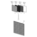
- each frame F1 contained in the image data is divided in time to obtain a plurality of subframes SF1.
- each frame F1 is divided in time to obtain four subframes SF11, SF12, SF13, and SF14.
- pixel shifting technology in other words wobbling technology, is used to sequentially project multiple subframes SF1 onto the display surface, thereby projecting an image onto the display surface at a higher resolution (here, 4K resolution) than the resolution that the modulation device possesses in the projection device can handle (here, 2K resolution).
- FIG. 3 is a schematic diagram of the pixel shifting technology.
- each frame F1 is divided in time to obtain a plurality of subframes SF1 (four subframes SF11, SF12, SF13, and SF14 in this example).
- the resolution of frame F1 is 4K
- the resolution of each subframe SF1 is 2K.
- Subframe SF11 is an image obtained by extracting odd-numbered pixels from among the pixels in the X direction (horizontal direction) of frame F1 and odd-numbered pixels from among the pixels in the Y direction (vertical direction) of frame F1.
- Subframe SF12 is an image obtained by extracting even-numbered pixels from among the pixels in the X direction of frame F1 and odd-numbered pixels from among the pixels in the Y direction of frame F1.
- Subframe SF13 is an image obtained by extracting even-numbered pixels from among the pixels in the X direction of frame F1 and even-numbered pixels from among the pixels in the Y direction of frame F1.
- Subframe SF14 is an image obtained by extracting odd-numbered pixels from among the pixels in the X direction of frame F1 and even-numbered pixels from among the pixels in the Y direction of frame F1.
- subframes SF11, SF12, SF13, and SF14 are also referred to as subframe "A,” subframe "B,” subframe “C,” and subframe “D,” respectively.
- each of the subframes SF11, SF12, SF13, and SF14 is projected sequentially onto the display surface while being shifted by half a pixel at a second frame rate (e.g., 240 fps), thereby projecting frame F1' onto the display surface.
- Frame F1' is an image formed by combining each of the subframes SF11, SF12, SF13, and SF14, and is an image with the same resolution as that of frame F1 (here, 4K resolution). Then, each of the frames F1' corresponding to each frame F1 is projected sequentially onto the display surface, so that an image corresponding to the image data is projected onto the display surface.
- the pattern image superimposition process and pattern image extraction process in the comparative example video processing method will be described.
- a first pattern image and a second pattern image are superimposed onto two of the multiple subframes.
- the subframe onto which the first pattern image is superimposed is also referred to as the "first superimposed subframe”
- the subframe onto which the second pattern image is superimposed is also referred to as the "second superimposed subframe.”
- a pattern image (here, a first pattern image) is extracted based on the first and second superimposed subframes captured by the imaging device.
- FIG. 4 is an overview diagram of the pattern image superimposition and extraction processes.
- FIG. 4(a) shows the pixel values of the blue signal in one horizontal line of the original image.
- FIG. 4(b) shows the pixel values of the blue signal in the above line of the first pattern image
- FIG. 4(c) shows the pixel values of the blue signal in the above line of the second pattern image.
- the first pattern image and the second pattern image are superimposed on each of two subframes out of the multiple subframes.
- the first overlaid subframe will be an image in which a first pattern image is overlaid on the original image
- the second overlaid subframe will be an image in which a second pattern image is overlaid on the original image.
- (d) of Figure 4 shows the pixel values of the blue signal in the one line of the first overlaid subframe in which the first pattern image is overlaid on the original image
- (e) of Figure 4 shows the pixel values of the blue signal in the one line of the second overlaid subframe in which the second pattern image is overlaid on the original image.
- the first and second superimposed subframes are captured by an imaging device, and a difference between the captured image of the first superimposed subframe and the captured image of the second superimposed subframe is calculated to obtain a difference image.
- (f) in FIG. 4 shows the pixel values of the blue signal in the above-mentioned one line of the difference image.
- the pattern shape of the difference image and the pattern shape of the first pattern image roughly match. This is because the original image can be removed by calculating the difference between the first and second superimposed subframes.
- this difference image is also referred to as the "third pattern image".
- the feature points of the third pattern image are compared with the reference feature points to detect the deviation of the display position of the image projected on the display surface, and the deviation of the display position of the image is corrected according to the detection result. Note that the detection of the deviation of the display position of the image and the correction of the deviation of the display position of the image will be explained in detail in [2. Configuration] below.
- the image processing method of the comparative example In order to accurately detect the deviation in the display position of the image, it is necessary to accurately extract a pattern image from the first and second superimposed subframes captured by the imaging device.
- the subframe on which the first pattern image is superimposed and the subframe on which the second pattern image is superimposed are, strictly speaking, different images from each other, so there is a problem that it is difficult to accurately extract the pattern image.
- the image processing method of the comparative example even if the difference between the first and second superimposed subframes is calculated, it is not possible to remove high-frequency components from the original image, and the parts that could not be removed are included in the pattern image as noise.
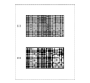
- FIG. 5 is an explanatory diagram of the problem with the image processing method of the comparative example.
- the images shown in (a) and (b) of FIG. 5 are both examples of pattern images that contain high-frequency components of the original image as noise, with (a) of FIG. 5 being an image created by simulation and (b) of FIG. 5 being an image captured by an actual device.
- a noise-free pattern image such as that shown in (a) of FIG. 10, which will be described later, but with the image processing method of the comparative example, a pattern image containing noise is obtained as shown in FIG. 5.
- the image processing method of the comparative example can detect a shift in the display position of an image without the user noticing, it also extracts a pattern image that contains noise.
- the image processing method of the comparative example detects a shift in the display position of an image projected onto a display surface based on a comparison between a pattern image that contains noise and a reference pattern image, and there is an issue in that it is difficult to accurately detect a shift in the display position of an image due to the effects of noise.
- each figure is a schematic diagram and is not necessarily a precise illustration.
- the same reference numerals are used for substantially the same configurations, and duplicate explanations may be omitted or simplified.
- FIG. 6 is a block diagram showing an overall configuration including a video processing system 100 according to an embodiment.
- the video processing system 100 includes a projection device 1, an imaging device 2, and a control device 3.
- the video processing system 100 is a system that processes video data transmitted from a playback device 4.
- Projection device 1 is a device with a projector function, and projects an image onto display surface 50 of screen 5 based on video data contained in a video signal transmitted from playback device 4. Note that projection device 1 is not limited to projecting an image onto display surface 50 of screen 5, and may also project an image onto display surface 50 of a surface of a structure other than a screen, such as a wall surface, for example.
- the imaging device 2 is a device with a camera function, and captures the image projected on the display surface 50.
- the imaging device 2 is a separate device from the projection device 1, but may be built into the projection device 1.
- the control device 3 is an information terminal such as a desktop or laptop personal computer, and controls the projection device 1 and the imaging device 2 by communicating with the projection device 1 and the imaging device 2 via a network N1 such as a LAN (Local Area Network).
- a network N1 such as a LAN (Local Area Network).
- the communication between the projection device 1 and the imaging device 2 and the control device 3 is performed according to a known network protocol such as HTTP (Hypertext Transfer Protocol), FTP (File Transfer Protocol), or TCP (Transmission Control Protocol).
- HTTP Hypertext Transfer Protocol
- FTP File Transfer Protocol
- TCP Transmission Control Protocol
- control device 3 is realized by installing software dedicated to the video processing system 100 on a general-purpose information terminal.
- control device 3 is not limited to a general-purpose information terminal, and may be an information terminal dedicated to the video processing system 100.
- information terminal is not limited to a personal computer, and may be realized by, for example, a smartphone or a tablet terminal.
- the playback device 4 is a device that has the function of playing back video recorded on optical media such as a DVD (Digital Versatile Disc, registered trademark) or a BD (Blu-ray (registered trademark) Disc). Note that the playback device 4 may also be a device that has the function of playing back video recorded on a storage device such as a HDD (Hard Disc Drive).
- DVD Digital Versatile Disc, registered trademark
- BD Blu-ray (registered trademark) Disc
- the playback device 4 may also be a device that has the function of playing back video recorded on a storage device such as a HDD (Hard Disc Drive).
- HDD Hard Disc Drive
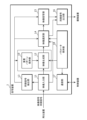
- Fig. 7 is a block diagram showing the configuration of the projection device 1 according to the embodiment.
- the projection device 1 includes an image input unit 11, an image generation unit 12, a synchronization signal extraction unit 13, an image selection unit 14, an image projection unit 15, a synchronization signal output unit 16, a communication unit 17, a parameter storage unit 18, and a superimposition pattern storage unit 19.
- the image input unit 11, the image generation unit 12, the synchronization signal extraction unit 13, the image selection unit 14, the image projection unit 15, the synchronization signal output unit 16, and the communication unit 17 may each be realized by a dedicated circuit, or may be realized by a processor executing a corresponding computer program stored in a memory.
- the video input unit 11 acquires a video signal input from the outside (here, the playback device 4) and converts the acquired video signal into an internal video signal.
- the resolution and frame rate of the video signal are not particularly limited.
- video signals having various resolutions or frame rates are input to the video input unit 11 from the playback device 4.
- the internal video signal has a resolution of 4K
- the frame rate is the first frame rate (e.g., 60 fps), similar to the video processing method of the comparative example.
- the video generation unit 12 performs various processes on the internal video signal from the video input unit 11. First, the video generation unit 12 performs an embedding determination process to determine whether or not it is possible to embed (superimpose) a pattern image into the internal video signal.
- the pattern image is embedded into the blue signal of the internal video signal, which has a relatively low brightness sensitivity for humans.
- the pattern images (first pattern image PP1 and second pattern image PP2 described below) are both superimposed on the video signal of the blue component. Therefore, in the embodiment, the video generation unit 12 performs an embedding determination process on the blue signal of the internal video signal.
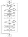
- FIG. 8 is a flowchart showing an example of the embedding determination process.
- the embedding determination process explained below is executed for each frame F1.
- the image generating unit 12 counts the number of pixels N for which the signal value (pixel value) of the blue signal in the internal image signal is within a predetermined range (S101).
- the predetermined range is the range between the upper and lower limit values of the signal value of the blue signal, which is a parameter stored in the parameter storage unit 18. If the signal value of the blue signal is within the predetermined range, it is possible to embed a pattern image by increasing or decreasing the signal value of the blue signal. On the other hand, if the signal value of the blue signal is outside the predetermined range, the blue signal becomes saturated when the signal value of the blue signal is increased or decreased, and it is not possible to embed a pattern image.
- the image generating unit 12 compares the counted number of pixels N with a value obtained by multiplying the number of all pixels included in the frame F1 by the effective ratio (S102).
- the effective ratio is a parameter stored in the parameter storage unit 18, and represents the ratio of pixels in which a pattern image can be embedded among all pixels in the frame F1. Then, if the number of pixels N is equal to or greater than the value obtained by multiplying the total number of pixels by the effective ratio (S102: Yes), the image generating unit 12 determines that a pattern image can be embedded in the frame F1 (S103). On the other hand, if the number of pixels N is less than the value obtained by multiplying the total number of pixels by the effective ratio (S102: No), the image generating unit 12 determines that a pattern image cannot be embedded in the frame F1 (S104).
- the image generating unit 12 executes the above steps S101 to S104. If the embedding mode is "disabled”, the image generating unit 12 executes step S104 without executing the above steps S101 and S102. If the embedding mode is "forced”, the image generating unit 12 executes step S103 without executing the above steps S101 and S102.
- the embedding mode is a parameter stored in the parameter storage unit 18.
- the image generating unit 12 performs geometric correction on the internal image signal according to a look-up table (LUT) for geometric correction. This process corrects the deviation in the display position of the image projected from the projection device 1 onto the display surface 50.
- LUT for geometric correction is a parameter stored in the parameter storage unit 18.
- the video generator 12 executes a generation process for generating a plurality of subframes SF1 by dividing the frame F1 in terms of time.
- the generation process will be described below with reference to FIG. 9.
- FIG. 9 is a flowchart showing an example of the generation process for a plurality of subframes SF1. The generation process described below is executed for each frame F1.
- the video generation unit 12 generates subframe "A" (i.e., subframe SF11) by extracting odd-numbered pixels from among the pixels in the X direction (horizontal direction) of frame F1 and odd-numbered pixels from among the pixels in the Y direction (vertical direction) of frame F1 (S201).
- the video generation unit 12 also generates subframe "B" (i.e., subframe SF12) by extracting even-numbered pixels from among the pixels in the X direction of frame F1 and odd-numbered pixels from among the pixels in the Y direction of frame F1 (S202).
- the video generation unit 12 also generates subframe "C" (i.e., subframe SF13) by extracting even-numbered pixels from among the pixels in the X direction of frame F1 and even-numbered pixels from among the pixels in the Y direction of frame F1 (S203).
- the video generator 12 also generates subframe "D" (i.e., subframe SF14) by extracting odd-numbered pixels from among the pixels in the X direction of frame F1 and even-numbered pixels from among the pixels in the Y direction of frame F1 (S204).
- Each of these multiple subframes SF1 is an image composed only of subpixels of the same phase in each pixel of frame F1. For example, if each pixel of frame F1 is composed of four subpixels "A”, “B”, “C”, and “D”, each pixel of subframe "A” is composed only of subpixel "A” of the corresponding pixel in frame F1.
- the video generation unit 12 refers to the result of the embedding determination process for frame F1 (S205). If the result of the embedding determination process is that the pattern image cannot be embedded (S205: No), the video generation unit 12 ends the generation process. On the other hand, if the result of the embedding determination process is that the pattern image can be embedded (S205: Yes), the video generation unit 12 then executes a process to determine the type of pattern image to embed in frame F1.
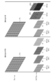
- FIG. 10 is a diagram showing an example of a pattern image.
- (a) to (c) of FIG. 10 respectively show the first pattern image PP1, and (d) to (f) of FIG. 10 respectively show the second pattern image PP2.
- (a) of FIG. 10 shows the first pattern image PP11 for the R (red) channel
- (b) of FIG. 10 shows the first pattern image PP21 for the G (green) channel
- (c) of FIG. 10 shows the first pattern image PP31 for the B (blue) channel.
- (d) of FIG. 10 shows the second pattern image PP12 for the R channel
- (e) of FIG. 10 shows the second pattern image PP22 for the G channel
- (f) of FIG. 10 shows the second pattern image PP32 for the B channel.
- the video generation unit 12 sequentially embeds a first pattern image PP11 and a second pattern image PP12 for the R channel, a first pattern image PP21 and a second pattern image PP22 for the G channel, and a first pattern image PP31 and a second pattern image PP32 for the B channel for each frame F1.
- the video generation unit 12 refers to the result of the embedding determination process in the frame preceding frame F1 (S206). Then, if a pattern image can be embedded in the previous frame (S206: Yes), the video generation unit 12 updates the type of pattern image to be embedded (S207). For example, if the first pattern image PP11 and the second pattern image PP12 for the R channel were embedded in the previous frame, the video generation unit 12 determines that the pattern images to be embedded in frame F1 are the first pattern image PP11 and the second pattern image PP12 for the G channel.
- the video generation unit 12 initializes the type of pattern image to be embedded (S208).
- initialization refers to determining that the pattern images to be embedded in frame F1 are the first pattern image PP11 and the second pattern image PP12 for the R channel.
- the video generation unit 12 embeds the first pattern image PP11 and the second pattern image PP12 for the R channel into that frame F1. As long as the determination result indicates that embedding is possible, the video generation unit 12 then embeds the first pattern image PP11 and the second pattern image PP12 for the R channel, the first pattern image PP11 and the second pattern image PP12 for the G channel, and the first pattern image PP11 and the second pattern image PP12 for the B channel, one by one, for each frame F1.
- subframe "B'” is an image in which the first pattern image PP1 is embedded (superimposed) in a composite image obtained by combining subframes "B" and "D".
- the image generating unit 12 generates subframe "B'” by adding the embedding signal value ⁇ to the signal value of the blue signal of the pixel corresponding to the white color of the first pattern image PP1 and subtracting the embedding signal value ⁇ from the signal value of the blue signal of the pixel corresponding to the black color of the first pattern image PP1 for each pixel of the composite image.
- the embedding signal value ⁇ is a parameter held in the parameter holding unit 18.
- the video generation unit 12 also generates subframe "D'" (S210).
- subframe "D'” is an image in which the second pattern image PP2 is embedded (superimposed) in a composite image obtained by combining subframes "B" and "D".
- the video generation unit 12 generates subframe "D'” by adding the embedding signal value ⁇ to the signal value of the blue signal of the pixel corresponding to the white color of the second pattern image PP2 and subtracting the embedding signal value ⁇ from the signal value of the blue signal of the pixel corresponding to the black color of the second pattern image PP2 for each pixel of the composite image.
- subframe “B'” corresponds to the first superimposed subframe SF21 (see FIG. 11 described later)
- subframe “D'” corresponds to the second superimposed subframe SF22 (see FIG. 11 described later).
- the composite image obtained by combining subframe “B” and subframe “D” corresponds to the "first subframe” and also to the "second subframe.”
- the first superimposed subframe SF21 is an image in which the first pattern image PP1 is superimposed on the first subframe (here, the above-mentioned composite image) based on the multiple subframes SF1.
- the second superimposed subframe SF22 is an image in which the second pattern image PP2 is superimposed on the second subframe (here, the above-mentioned composite image) based on the multiple subframes SF1.
- the first subframe and the second subframe are both images in which two subframes (here, subframes "B" and "D") out of the multiple subframes SF1 are composited, and are the same image.
- subframes SF11 and SF13 in which neither the first pattern image PP1 nor the second pattern image PP2 is superimposed, are both images that are different from both the first superimposed subframe SF21 and the second superimposed subframe SF22.
- the synchronization signal extraction unit 13 generates an internal synchronization signal with the same frame rate as the frame rate of the internal video signal (here, 60 fps) based on a synchronization signal input together with the video signal from outside (here, the playback device 4).
- the internal synchronization signal is provided to the video generation unit 12, the video selection unit 14, and the video projection unit 15, respectively.
- the video generation unit 12, the video selection unit 14, and the video projection unit 15 operate for each frame based on the internal synchronization signal.
- the image selection unit 14 selects a subframe set of images to be projected from the image projection unit 15 onto the display surface 50 according to the result of the embedding determination process for frame F1 in the image generation unit 12.
- the subframe set is composed of multiple subframes SF1 corresponding to frame F1.
- FIG. 11 is an explanatory diagram of an example of the operation of the image selection unit 14 of the projection device 1 according to the embodiment.
- the image selection unit 14 selects a subframe set consisting of subframes "A”, “B”, “C”, and “D".
- subframes "A”, “B”, “C”, and “D” correspond to subframes SF11, SF12, SF13, and SF14, respectively.
- the video selection unit 14 selects a subframe set consisting of subframes "A”, “B'", “C”, and "D'".
- subframes "A”, “B'", “C”, and “D'” correspond to subframe SF11, first superimposed subframe SF21, subframe SF13, and second superimposed subframe SF22, respectively.
- the video selection unit 14 selects a subframe set to be output to the display surface 50 depending on the result of the embedding determination process in the video generation unit 12. Also, as already mentioned, in the embedding determination process, for each frame F1, it is determined whether or not it is possible to embed a pattern image by referring to the signal value of the blue signal in the internal video signal. In other words, the video processing system 100 according to the embodiment determines whether or not to output the first superimposed subframe SF21 and the second superimposed subframe SF22 to the display surface 50 based on the pixel value of the video signal in frame F1 (here, the signal value of the blue signal).
- the image projection unit 15 projects an image onto the display surface 50 according to the image signal of the subframe set selected by the image selection unit 14.
- the specific configuration and operation of the image projection unit 15 will be described below with reference to Figs. 12 and 13.
- Fig. 12 is a schematic diagram of the image projection unit 15 of the projection device 1 according to the embodiment.
- Fig. 13 is a diagram showing the correlation between the control signal given to the light path shift element 153 and the image signal.
- the image projection unit 15 includes a light source 151, a modulation device 152, a light path shift element 153, and a projection lens 154.
- the light source 151 has, for example, an ultra-high pressure mercury lamp or a metal halide lamp, and outputs parallel light to the modulation device 152.
- the modulation device 152 modulates the light output from the light source 151 according to the input video signal, and outputs the modulated light to the light path shift element 153.
- the light path shift element 153 is made of, for example, a parallel plate glass having optical transparency, and tilts according to the signal voltage of the control signal.
- the optical path of the light incident on the light path shift element 153 shifts according to the tilt of the light path shift element 153.
- the control signal includes a horizontal control signal and a vertical control signal. Therefore, the light path shift element 153 can tilt in either the horizontal direction or the vertical direction according to the signal voltage of the control signal.
- the projection lens 154 collects the light output from the light path shift element 153 and outputs it to the display surface 50, forming an image on the display surface 50 that corresponds to the light output from the light path shift element 153.
- an image shifting technique is used to sequentially project each subframe SF1 included in the subframe set selected by the image selection unit 14 onto the display surface 50 while shifting it by half a pixel at a second frame rate (here, 240 fps).
- the horizontal control signal and the vertical control signal are both rectangular wave signals that alternate between high and low levels in a first period Td1 (here, 1/120 seconds).
- the horizontal control signal and the vertical control signal are out of phase with each other by 1/4 of the first period Td1. Therefore, the combination of the signal voltage of the horizontal control signal and the signal voltage of the vertical control signal changes in a second period Td2 (here, 1/240 seconds).
- the image projection unit 15 projects light corresponding to subframe "A" onto the display surface 50 at the timing when the horizontal control signal is at a high level and the vertical control signal is at a high level. As a result, the subframe "A" is projected onto the display surface 50.
- the image projection unit 15 projects light corresponding to subframe "B” or subframe “B'” onto the display surface 50 when the horizontal control signal goes low and the vertical control signal goes high.
- the subframe “B” or subframe “B'” is projected onto the display surface 50 at a position shifted by half a pixel in the horizontal direction from the display position of the subframe "A.”
- the image projection unit 15 projects light corresponding to subframe "C" onto the display surface 50 at the timing when the horizontal control signal is at a low level and the vertical control signal is at a low level.
- subframe "C” is projected onto the display surface 50 at a position shifted by half a pixel in the horizontal direction and half a pixel in the vertical direction from the display position of subframe "A.”
- the image projection unit 15 projects light corresponding to subframe "D” or subframe “D'” onto the display surface 50 when the horizontal control signal is at a high level and the vertical control signal is at a low level.
- the subframe “D” or subframe “D'” is projected onto the display surface 50 at a position that is shifted vertically by half a pixel from the display position of the subframe "A.”
- the image processing system 100 uses image shifting technology to sequentially project multiple subframes SF1 (here, subframe “A”, subframe “B” (or “B'"), subframe “C”, and subframe “D” (or “D'”)) onto the display surface 50.
- the image processing system 100 according to the embodiment projects an image onto the display surface 50 at a higher resolution (here, 4K resolution) than the resolution that the modulation device 152 of the projection device 1 can handle (here, 2K resolution).
- the synchronization signal output unit 16 outputs a synchronization signal to the imaging device 2.
- the synchronization signal is a pulse signal that goes high at the timing when the first superimposed subframe SF21 and the second superimposed subframe SF22 are projected onto the display surface 50. Note that if the first superimposed subframe SF21 and the second superimposed subframe SF22 are not included in the subframe set selected by the video selection unit 14, the synchronization signal output unit 16 does not output a synchronization signal to the imaging device 2.
- the communication unit 17 is a communication interface for communicating with the control device 3 via the network N1.
- the communication unit 17 receives a parameter setting command sent from the control device 3, and changes various parameters stored in the parameter storage unit 18 according to the content of the received parameter setting command.
- the communication between the communication unit 17 and the control device 3 may be wired communication or wireless communication.
- the parameter storage unit 18 is a semiconductor memory or the like, and stores various parameters referenced when the projection device 1 operates.
- the parameter storage unit 18 stores the upper and lower limit values of the signal value of the blue signal, which are parameters referenced in the embedding determination process already described, the effective ratio, the embedding signal value ⁇ , and the embedding mode.
- the parameter storage unit 18 also stores the LUT for geometric correction already described. Note that these parameters are merely examples, and the parameter storage unit 18 may store further parameters.
- the superimposition pattern storage unit 19 is a semiconductor memory or the like, and stores bitmap data of the pattern images (first pattern image PP1 and second pattern image PP2) to be superimposed on the subframe SF1. Note that the parameter storage unit 18 and the superimposition pattern storage unit 19 may be realized by the same semiconductor memory.
- Fig. 14 is a block diagram showing the configuration of the imaging device 2 according to the embodiment.
- the imaging device 2 includes a communication unit 21, a screen generation unit 22, a synchronization signal input unit 23, an imaging unit 24, a pattern detection unit 25, a parameter storage unit 26, and a superimposition pattern storage unit 27.
- the communication unit 21, the screen generation unit 22, the synchronization signal input unit 23, the imaging unit 24, and the pattern detection unit 25 may each be realized by a dedicated circuit, or may be realized by a processor executing a corresponding computer program stored in a memory.
- the communication unit 21 is a communication interface for communicating with the control device 3 via the network N1.
- the communication unit 21 receives commands sent from the control device 3 and relays the received commands to the screen generation unit 22.
- the communication unit 21 also transmits the results of the processing executed by the screen generation unit 22 to the control device 3. Note that the communication between the communication unit 21 and the control device 3 may be wired communication or wireless communication.
- the screen generation unit 22 generates a screen to be displayed on a display attached to the control device 3 by the screen display unit 32 (described later) of the control device 3.
- the screen generation unit 22 generates an HTML page in response to a command from the control device 3.
- the screen generation unit 22 generates an HTML page including various current parameters of the imaging device 2 and an icon for accepting changes to the various parameters in response to a command from the control device 3.
- the screen generation unit 22 executes a process for changing various parameters of the imaging device 2, or a process for starting or ending imaging by the imaging unit 24 in response to a command from the control device 3, and generates an HTML page including the processing results.
- the synchronization signal input unit 23 receives the synchronization signal transmitted from the projection device 1 and provides the received synchronization signal to the imaging unit 24.
- the imaging unit 24 captures the image projected on the display surface 50.
- the imaging unit 24 starts exposure at a timing according to the trigger mode.
- the trigger mode is a parameter stored in the parameter storage unit 26.
- the trigger mode is "synchronization signal”
- the imaging unit 24 starts exposure at the timing when the synchronization signal pulse from the projection device rises. That is, in this case, the imaging unit 24 captures only the first superimposed subframe SF21 and the second superimposed subframe SF22 of the image projected on the display surface 50.
- the trigger mode is "program”
- the imaging unit 24 starts exposure upon receiving a command to start imaging from the control device 3.
- the time from when the imaging unit 24 starts to when it finishes exposure is determined by the exposure time (here, in milliseconds) stored in the parameter storage unit 26. Also, if the trigger delay amount (here, in microseconds) stored in the parameter storage unit 26 is not zero, the imaging unit 24 starts exposure with a delay of the trigger delay amount after the rising edge of the synchronization signal pulse.
- the pattern detection unit 25 executes a detection process to detect a pattern image from the first superimposed subframe SF21 and the second superimposed subframe SF22 captured by the imaging unit 24.
- the detection process will be described below with reference to FIG. 15.
- FIG. 15 is a flowchart showing an example of the pattern image detection process. The detection process described below is executed each time the first superimposed subframe SF21 and the second superimposed subframe SF22 are captured by the imaging unit 24.
- the pattern detection unit 25 obtains a difference image by calculating the difference between the first and second superimposed subframes SF21 and SF22 captured by the imaging unit 24 (S301). Note that the display positions of the first and second superimposed subframes SF21 and SF22 on the display surface 50 are shifted from each other by the shift amount caused by the optical path shift element 153 because pixel shift technology is used in the image projection unit 15 of the projection device 1. Therefore, the pattern detection unit 25 shifts either the first or second superimposed subframe SF21 or SF22 by the shift amount, and then calculates the difference.
- the difference image acquired in step S301 is either a pattern image for the R channel, a pattern image for the G channel, or a pattern image for the B channel.
- the pattern detection unit 25 will acquire the pattern image for the R channel when the image corresponding to frame F1 is projected onto the display surface 50.
- the pattern detection unit 25 averages the multiple difference images (S302).
- the pattern detection unit 25 sequentially acquires a difference image corresponding to a pattern image for the R channel, a difference image corresponding to a pattern image for the G channel, and a difference image corresponding to a pattern image for the B channel for each frame F1. Therefore, as long as a pattern image is embedded in each frame F1 in the projection device 1, the pattern detection unit 25 can acquire a difference image corresponding to a pattern image for the same channel every three frames. Therefore, when the pattern detection unit 25 acquires a predetermined number of difference images (e.g., 10) for each of the R channel, G channel, and B channel, it averages these multiple difference images. This makes it possible to reduce noise contained in the averaged difference images.
- a predetermined number of difference images e.g. 10
- the pattern detection unit 25 determines the type of pattern image by pattern matching the black and white binarized difference image with the R channel pattern image template, the G channel pattern image template, and the B channel pattern image template stored in the superimposition pattern storage unit 27 (S304). For example, if the black and white binarized difference image and the G channel pattern image template roughly match, the pattern detection unit 25 determines that the difference image is a G channel pattern image.
- the pattern detection unit 25 writes the difference image, for which the type of pattern image has been determined, into memory as the third pattern image PP3 (S305).
- the imaging device 2 acquires the third pattern image PP3 for the R channel, the third pattern image PP3 for the G channel, and the third pattern image PP3 for the B channel.
- the parameter storage unit 26 is a semiconductor memory or the like, and stores various parameters that are referenced when the imaging device 2 operates.
- the parameter storage unit 26 stores the trigger mode, exposure time, and trigger delay amount already described. Note that these parameters are merely examples, and the parameter storage unit 26 may store further parameters.
- the superimposition pattern storage unit 27 is a semiconductor memory or the like, and stores bitmap data of the pattern image template for the R channel, the pattern image template for the G channel, and the pattern image template for the B channel, which are used in the detection process already described. Note that the parameter storage unit 26 and the superimposition pattern storage unit 27 may be realized by the same semiconductor memory.
- Fig. 16 is a block diagram showing the configuration of the control device 3 according to the embodiment.
- the control device 3 includes an input unit 31, a screen display unit 32, a communication unit 33, a deviation correction unit 34, and a data storage unit 35.
- the input unit 31, the screen display unit 32, the communication unit 33, and the deviation correction unit 34 may each be realized by a dedicated circuit, or may be realized by a processor executing a corresponding computer program stored in a memory.
- the input unit 31 accepts input from the user using, for example, a keyboard or a pointing device such as a mouse.
- the input unit 31 gives control commands to the projection device 1 or the imaging device 2 in response to the input from the user.
- the control commands include, for example, an instruction to change various parameters of the imaging device 2, an instruction to transmit various parameters of the imaging device 2, an instruction to transmit the third pattern image PP3 from the imaging device 2, an instruction to initialize the misalignment correction process by the misalignment correction unit 34 described below, or an instruction to start or end the misalignment correction process by the misalignment correction unit 34.
- the screen display unit 32 displays a UI (User Interface) screen for operating the control device 3 on a display attached to the control device 3.
- UI User Interface
- the screen display unit 32 displays an HTML page or the like generated by the screen generation unit 22 of the imaging device 2 on the display.
- the communication unit 33 is a communication interface for communicating with each of the projection device 1 and the imaging device 2 via the network N1.
- the communication unit 33 transmits control commands to the projection device 1 or the imaging device 2.
- the communication unit 33 also transmits LUT data for geometric correction after correction by the misalignment correction process described below to the projection device 1. Note that the communication between the communication unit 33 and the projection device, and the communication between the communication unit 33 and the imaging device 2 may be wired communication or wireless communication.
- the misalignment correction unit 34 has a function of executing initialization of the misalignment correction process.
- the initialization of the misalignment correction process will be described below with reference to FIG. 17.
- FIG. 17 is a flowchart showing an example of the initialization of the misalignment correction process.
- the initialization of the misalignment correction process may be executed once in response to user input received by the input unit 31 before executing the misalignment correction process, for example, when starting to use the video processing system 100.
- the misalignment correction unit 34 acquires LUT data for geometric correction from the projection device 1 (S401). Next, the misalignment correction unit 34 acquires a third pattern image PP3 for the R channel, a third pattern image PP3 for the G channel, and a third pattern image PP3 for the B channel from the imaging device 2, and detects feature points SP1 of the third pattern image PP3 from these images (S402).
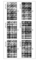
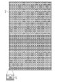
- FIG. 18 is a diagram showing an example of the feature point SP1 of the third pattern image PP3.
- FIG. 18 shows the third pattern image PP3 obtained by combining the third pattern image PP3 for the R channel, the third pattern image PP3 for the G channel, and the third pattern image PP3 for the B channel.
- the third pattern images PP3 for each channel are combined by coloring the white pixels in the third pattern image PP3 for the R channel red, the white pixels in the third pattern image PP3 for the G channel green, and the white pixels in the third pattern image PP3 for the B channel blue.
- each pixel is color-coded according to the type of hatching.
- feature point SP1 is the intersection of four regions, where the upper region, lower region, right region, and left region have different colors.
- the synthesized third pattern image PP3 there is only one point where the color of the upper region, the color of the lower region, the color of the right region, and the color of the left region form a specific combination.
- the misalignment correction unit 34 detects the intersection of the four regions where the color combination forms the specific combination as feature point SP1.
- the misalignment correction unit 34 stores data linking each point of the geometric correction LUT with the detected feature point SP1 of the third pattern image PP3 as initial data in the data storage unit 35 (S403).
- the misalignment correction unit 34 also has a function of executing misalignment correction processing.
- the misalignment correction processing will be described below with reference to FIG. 19.
- FIG. 19 is a flowchart showing an example of the misalignment correction processing.
- the misalignment correction processing is executed in response to input from the user received by the input unit 31 after the misalignment correction processing has been initialized. Note that the misalignment correction processing may be executed periodically, regardless of input from the user.
- misalignment correction unit 34 If the misalignment correction unit 34 has not received an instruction to end the process from the user (S501: No), it repeats the series of processes in steps S502 to S507 described below. On the other hand, if the misalignment correction unit 34 has received an instruction to end the process from the user (S501: Yes), it ends the misalignment correction process.
- the misalignment correction unit 34 waits until the pattern image (third pattern image PP3 for each channel) acquired from the imaging device 2 is updated (S502: No). Then, when the pattern image acquired from the imaging device 2 is updated (S502: Yes), the misalignment correction unit 34 detects the feature point SP1 based on the acquired third pattern image PP3 for each channel (S503).
- the method of detecting the feature point SP1 has already been described, so the description will be omitted here.
- the deviation correction unit 34 compares the detected feature point SP1 with the feature point SP1 included in the initial data (S504).
- the deviation correction unit 34 compares the XY plane coordinates of the detected feature point SP1 with the XY plane coordinates of the feature point SP1 included in the initial data.
- the misalignment correction unit 34 does not update the LUT for geometric correction and the initial data.
- the misalignment correction unit 34 If there is deviation in the position of feature point SP1 (S505: Yes), the misalignment correction unit 34 generates a LUT for geometric correction that reduces the deviation to zero, and updates the LUT for geometric correction (S506).
- the misalignment correction unit 34 updates the initial data using the updated LUT for geometric correction (S507). Specifically, the misalignment correction unit 34 updates the detected feature point SP1 as the feature point SP1 included in the initial data.
- the misalignment correction unit 34 transmits the updated (corrected) LUT data for geometric correction to the projection device 1 via the communication unit 33 and the network N1.
- the projection device 1 then performs geometric correction on the internal video signal according to the acquired corrected LUT for geometric correction. This makes it possible to correct the misalignment of the display position of the image on the display surface 50.
- the data storage unit 35 is a semiconductor memory or the like, and stores initial data including LUT data for geometric correction acquired from the imaging device 2, and the third pattern image PP3 for each channel acquired from the imaging device 2, etc.
- Fig. 20 is a flowchart showing an example of the operation of the video processing system 100 according to the embodiment.
- the video processing system 100 acquires three or more subframes SF1 obtained by temporally dividing a frame F1 included in the video data (S1).
- step S1 is executed by the video generation unit 12 of the projection device 1.
- the video processing system 100 outputs the first superimposed subframe SF21 and the second superimposed subframe SF22 to be displayed on the display surface 50 (S2).
- the first superimposed subframe SF21 is an image in which a first pattern image PP1 is superimposed on a first subframe based on a plurality of subframes SF1.
- the second superimposed subframe SF2 is an image in which a second pattern image PP2, which is obtained by inverting the pixel values of the first pattern image PP1, is superimposed on a second subframe based on a plurality of subframes SF1.
- step S2 is executed by the video generation unit 12, video selection unit 14, and video projection unit 15 of the projection device 1.
- step S3 the video processing system 100 captures the first superimposed subframe SF21 and the second superimposed subframe SF22 displayed on the display surface 50 (step S3).
- step S3 is executed by the imaging unit 24 and the pattern detection unit 25 of the imaging device 2.
- step S4 the video processing system 100 acquires a third pattern image PP3 from the difference between the acquired first superimposed sub-frame SF21 and second superimposed sub-frame SF22 (step S4).
- step S4 is executed by the pattern detection unit 25 of the imaging device 2.
- the image processing system 100 detects the deviation of the display position of the image projected on the display surface 50 by comparing the feature point SP1 of the acquired third pattern image PP3 with the reference feature point (S5).
- the reference feature point is the feature point SP1 of the third pattern image PP3 contained in the initial data already mentioned.
- the execution entity of step S5 is the deviation correction unit 34 of the control device 3.
- the video processing system 100 executes a process of updating the LUT for geometric correction to correct the detected display position deviation, but this process does not have to be executed.
- a pattern image (third pattern image PP3) is extracted based on the first superimposed subframe SF21 and the second superimposed subframe SF22 captured by the imaging device 2.
- the first subframe which is an image on which the first pattern image PP1 is superimposed when generating the first superimposed subframe SF21
- the second subframe which is an image on which the second pattern image PP2 is superimposed when generating the second superimposed subframe SF22, are the same image.
- the third pattern image PP3 can be extracted with high accuracy, which has the advantage that it is easy to accurately detect a shift in the display position of the image without the user noticing.
- the first subframe and the second subframe are both images obtained by combining two subframes among the plurality of subframes SF1, but this is not limited thereto.
- the first subframe and the second subframe may both be one subframe among the plurality of subframes SF1.
- Fig. 21 is an explanatory diagram of an example of the operation of the projection device 1 according to the first modified example of the embodiment.
- Fig. 22 is a schematic diagram of the image projection section 15 of the projection device 1 according to the first modified example of the embodiment.
- Fig. 23 is a diagram showing the correlation between the control signal and the image signal given to the light path shift element 153 in the first modified example of the embodiment. Below, a description of the points common to the image processing system 100 according to the embodiment will be omitted.
- the video selection unit 14 selects a subframe set consisting of subframes "A”, “A”, “C'”, and “C”".
- subframes "A”, “C'”, and “C”” correspond to subframe SF11, first superimposed subframe SF21, and second superimposed subframe SF22, respectively.
- subframes "B'" and “D” instead of generating subframes "B'" and “D", the video generator 12 generates subframes "C'" and "C"".
- subframe "C'” is an image in which the first pattern image PP1 is embedded (superimposed) in subframe "C”.
- subframe "C” is an image in which the second pattern image PP2 is embedded in subframe "C”.
- the first subframe and the second subframe are both one subframe (here, subframe "C") out of the multiple subframes SF1.
- the video projection unit 15 uses a pixel shifting technique different from that of the embodiment to sequentially project each subframe SF1 included in the subframe set selected by the video selection unit 14 onto the display surface 50 while shifting them at a third frame rate (here, 120 fps), as shown in FIG. 22.
- a third frame rate here, 120 fps
- the image projection unit 15 continuously projects light corresponding to subframe "A" onto the display surface 50 at the timing when the horizontal control signal is at a high level and the vertical control signal is at a high level. As a result, subframe "A" is continuously projected onto the display surface 50.
- the image projection unit 15 first projects light corresponding to subframe "C'” onto the display surface 50, and then projects light corresponding to subframe "C”" onto the display surface 50.
- the subframes "C'” and “C”” are projected onto the display surface 50 at positions shifted by half a pixel in the horizontal and vertical directions from the display position of the subframe "A".
- noise can be made less likely to be included in the third pattern image PP3, and the third pattern image PP3 can be extracted with high accuracy, which has the advantage that it is easier to accurately detect a shift in the display position of the image without the user noticing.
- FIG. 24 is a schematic diagram showing an overall configuration including an image processing system 100 according to the second modified example of the embodiment.
- images are projected onto a display surface 50 from multiple projection devices 1 (here, two projection devices 1A, 1B), respectively, and a composite image is projected onto the display surface 50.
- the control device 3 may control each of the projection devices 1A, 1B to alternately cause the multiple projection devices 1 to perform the process of outputting the first superimposed sub-frame SF21 and the second superimposed sub-frame SF22 onto the display surface 50.
- the first overlapping sub-frame SF21 and the second overlapping sub-frame SF22 projected from each projection device 1 do not overlap on the display surface 50, which has the advantage that noise is less likely to be included in the third pattern image PP3.
- the image processing system 100 is realized by a plurality of devices, but this is not limiting, and for example, the image processing system 100 may be realized by a single device.
- processing performed by a specific processing unit may be executed by another processing unit.
- the order of multiple processes may be changed, and multiple processes may be executed in parallel.
- each component may be realized by executing a software program suitable for each component.
- Each component may be realized by a program execution unit such as a CPU or processor reading and executing a software program recorded on a recording medium such as a hard disk or semiconductor memory.
- each component may be realized by hardware.
- Each component may be a circuit (or an integrated circuit). These circuits may form a single circuit as a whole, or each may be a separate circuit. Furthermore, each of these circuits may be a general-purpose circuit, or a dedicated circuit.
- the general or specific aspects of the present disclosure may be realized as a system, an apparatus, a method, an integrated circuit, a computer program, or a computer-readable recording medium such as a CD-ROM.
- the present disclosure may be realized as any combination of a system, an apparatus, a method, an integrated circuit, a computer program, and a recording medium.
- the present disclosure may also be realized as an image processing method executed by a computer such as the image processing system of the above-described embodiment.
- the present disclosure may also be realized as a program (computer program product) for causing a computer to execute such an image processing method, or as a computer-readable non-transitory recording medium on which such a program is recorded.
- this disclosure also includes forms obtained by applying various modifications to each embodiment that a person skilled in the art may conceive, or forms realized by arbitrarily combining the components and functions of each embodiment within the scope of the spirit of this disclosure.
- a frame F1 included in video data is divided in time to obtain a plurality of subframes SF1 (three or more).
- a second superimposed subframe SF22 in which a second pattern image PP2 in which the pixel values of the first pattern image PP1 are inverted is superimposed on a second subframe based on the plurality of subframes SF1 are output to be displayed on the display surface 50.
- the first superimposed subframe SF21 and the second superimposed subframe SF22 displayed on the display surface 50 are obtained by imaging.
- a third pattern image PP3 is obtained from the difference between the obtained first superimposed subframe SF21 and second superimposed subframe SF22.
- this image processing method by comparing the feature point SP1 of the acquired third pattern image PP3 with the reference feature point, a deviation in the display position of the image projected onto the display surface 50 is detected.
- the first sub-frame and the second sub-frame are the same image.
- This type of image processing method has the advantage that noise is less likely to be included in the third pattern image PP3 and the third pattern image PP3 can be extracted with high accuracy, making it easier to accurately detect a shift in the display position of the image without the user noticing.
- each of the multiple sub-frames SF1 is an image composed only of sub-pixels of the same phase in each pixel of the frame F1.
- This type of image processing method has the advantage that it is easy to make the first subframe and the second subframe the same image.
- the first subframe and the second subframe are both images formed by combining two subframes SF1 out of the multiple subframes SF1.
- This type of image processing method has the advantage that it is easy to make the first subframe and the second subframe the same image while maintaining the quality of the image projected onto the display surface 50.
- the first subframe and the second subframe are both one subframe out of the multiple subframes SF1.
- This type of image processing method has the advantage that it is easy to make the first subframe and the second subframe the same image.
- the first pattern image PP1 and the second pattern image PP2 are both superimposed on the video signal of the blue component.
- This type of image processing method has the advantage that the pattern image is less noticeable to the user because it is superimposed on the blue signal, which humans have a relatively low sensitivity to brightness.
- a decision is made as to whether or not to output the first superimposed sub-frame SF21 and the second superimposed sub-frame SF22 to the display surface 50 based on the pixel values of the video signal in frame F1.
- This type of video processing method has the advantage that the video signal is less likely to become saturated when the pattern image is superimposed on the video signal, making it easier to superimpose the pattern image without distorting it.
- any one of the first to sixth aspects there are a plurality of projection devices 1 that project images onto the display surface 50. Furthermore, in this image processing method, when a composite image is projected onto the display surface 50 by projecting images from the plurality of projection devices 1 onto the display surface 50, the plurality of projection devices 1 are caused to alternately execute the process of outputting the first superimposed sub-frame SF21 and the second superimposed sub-frame SF22 onto the display surface 50.
- This type of image processing method has the advantage that multiple projection devices 1 do not simultaneously execute the process of outputting the first superimposed sub-frame SF21 and the second superimposed sub-frame SF22 to the display surface 50, making it easier to obtain a noise-free third pattern image PP3.
- the program according to the eighth aspect causes one or more processors to execute the image processing method according to any one of the first to seventh aspects.
- Such a program has the advantage that noise is less likely to be included in the third pattern image PP3 and the third pattern image PP3 can be extracted with high accuracy, making it easier to accurately detect a shift in the display position of the image without the user noticing.
- the image processing system 100 relating to the ninth aspect includes a first acquisition unit (image generation unit 12 of the projection device 1), an output unit (image generation unit 12, image selection unit 14, and image projection unit 15 of the projection device 1), a second acquisition unit (imaging unit 24 and pattern detection unit 25 of the imaging device 2), a third acquisition unit (pattern detection unit 25 of the imaging device 2), and a detection unit (deviation correction unit 34 of the control device 3).
- the first acquisition unit acquires a plurality of sub-frames SF1, three or more, obtained by temporally dividing a frame F1 included in the image data.
- the output unit outputs a first superimposed subframe SF21 in which a first pattern image PP1 is superimposed on a first subframe based on a plurality of subframes SF1, and a second superimposed subframe SF22 in which a second pattern image PP2 in which pixel values of the first pattern image PP1 are inverted is superimposed on a second subframe based on a plurality of subframes SF1, so as to be displayed on the display surface 50.
- the second acquisition unit acquires the first superimposed subframe SF21 and the second superimposed subframe SF22 displayed on the display surface 50 by imaging.
- the third acquisition unit acquires a third pattern image PP3 from the difference between the acquired first superimposed subframe SF21 and the second superimposed subframe SF22.
- the detection unit detects a deviation in the display position of the image projected on the display surface 50 by comparing the feature point SP1 of the acquired third pattern image PP3 with the reference feature point.
- the first subframe and the second subframe are
- Such an image processing system 100 has the advantage that noise is less likely to be included in the third pattern image PP3 and the third pattern image PP3 can be extracted with high accuracy, making it easier to accurately detect a shift in the display position of the image without the user noticing.
Landscapes
- Engineering & Computer Science (AREA)
- Theoretical Computer Science (AREA)
- Physics & Mathematics (AREA)
- General Physics & Mathematics (AREA)
- Multimedia (AREA)
- Signal Processing (AREA)
- Computer Vision & Pattern Recognition (AREA)
- Health & Medical Sciences (AREA)
- General Engineering & Computer Science (AREA)
- Human Computer Interaction (AREA)
- Artificial Intelligence (AREA)
- Computing Systems (AREA)
- Databases & Information Systems (AREA)
- Evolutionary Computation (AREA)
- General Health & Medical Sciences (AREA)
- Medical Informatics (AREA)
- Software Systems (AREA)
- Computer Hardware Design (AREA)
- Geometry (AREA)
- Transforming Electric Information Into Light Information (AREA)
Priority Applications (2)
| Application Number | Priority Date | Filing Date | Title |
|---|---|---|---|
| JP2024574436A JPWO2024162042A1 (https=) | 2023-02-03 | 2024-01-19 | |
| US19/285,139 US20250356463A1 (en) | 2023-02-03 | 2025-07-30 | Video processing method, program, and video processing system |
Applications Claiming Priority (2)
| Application Number | Priority Date | Filing Date | Title |
|---|---|---|---|
| JP2023015551 | 2023-02-03 | ||
| JP2023-015551 | 2023-02-03 |
Related Child Applications (1)
| Application Number | Title | Priority Date | Filing Date |
|---|---|---|---|
| US19/285,139 Continuation US20250356463A1 (en) | 2023-02-03 | 2025-07-30 | Video processing method, program, and video processing system |
Publications (1)
| Publication Number | Publication Date |
|---|---|
| WO2024162042A1 true WO2024162042A1 (ja) | 2024-08-08 |
Family
ID=92146612
Family Applications (1)
| Application Number | Title | Priority Date | Filing Date |
|---|---|---|---|
| PCT/JP2024/001466 Ceased WO2024162042A1 (ja) | 2023-02-03 | 2024-01-19 | 映像処理方法、プログラム、及び映像処理システム |
Country Status (3)
| Country | Link |
|---|---|
| US (1) | US20250356463A1 (https=) |
| JP (1) | JPWO2024162042A1 (https=) |
| WO (1) | WO2024162042A1 (https=) |
Citations (6)
| Publication number | Priority date | Publication date | Assignee | Title |
|---|---|---|---|---|
| JP2004146936A (ja) * | 2002-10-22 | 2004-05-20 | Mitsubishi Electric Corp | カラーディスプレイ装置 |
| US20100142754A1 (en) * | 2008-12-10 | 2010-06-10 | Industrial Technology Research Institute | Inspection method and system for display |
| JP2016518618A (ja) * | 2013-03-14 | 2016-06-23 | ピクストロニクス,インコーポレイテッド | 画像サブフレームの選択的照明のために構成されたディスプレイ装置 |
| WO2017154628A1 (ja) * | 2016-03-11 | 2017-09-14 | ソニー株式会社 | 画像処理装置および方法 |
| JP2020025228A (ja) * | 2018-08-08 | 2020-02-13 | キヤノン株式会社 | 画像処理装置、電子透かし埋め込み装置、パターン画像の埋め込み方法、およびプログラム |
| JP2022091477A (ja) * | 2020-12-09 | 2022-06-21 | キヤノン株式会社 | 画像投射装置、画像投射装置の制御方法、及びプログラム |
-
2024
- 2024-01-19 JP JP2024574436A patent/JPWO2024162042A1/ja active Pending
- 2024-01-19 WO PCT/JP2024/001466 patent/WO2024162042A1/ja not_active Ceased
-
2025
- 2025-07-30 US US19/285,139 patent/US20250356463A1/en active Pending
Patent Citations (6)
| Publication number | Priority date | Publication date | Assignee | Title |
|---|---|---|---|---|
| JP2004146936A (ja) * | 2002-10-22 | 2004-05-20 | Mitsubishi Electric Corp | カラーディスプレイ装置 |
| US20100142754A1 (en) * | 2008-12-10 | 2010-06-10 | Industrial Technology Research Institute | Inspection method and system for display |
| JP2016518618A (ja) * | 2013-03-14 | 2016-06-23 | ピクストロニクス,インコーポレイテッド | 画像サブフレームの選択的照明のために構成されたディスプレイ装置 |
| WO2017154628A1 (ja) * | 2016-03-11 | 2017-09-14 | ソニー株式会社 | 画像処理装置および方法 |
| JP2020025228A (ja) * | 2018-08-08 | 2020-02-13 | キヤノン株式会社 | 画像処理装置、電子透かし埋め込み装置、パターン画像の埋め込み方法、およびプログラム |
| JP2022091477A (ja) * | 2020-12-09 | 2022-06-21 | キヤノン株式会社 | 画像投射装置、画像投射装置の制御方法、及びプログラム |
Also Published As
| Publication number | Publication date |
|---|---|
| US20250356463A1 (en) | 2025-11-20 |
| JPWO2024162042A1 (https=) | 2024-08-08 |
Similar Documents
| Publication | Publication Date | Title |
|---|---|---|
| JP6381215B2 (ja) | 画像処理装置、画像処理方法、表示装置、表示装置の制御方法、及び、プログラム | |
| JP6155717B2 (ja) | 画像処理装置、プロジェクター及び画像処理方法 | |
| JP2006197443A (ja) | 画像処理システム、プロジェクタ、プログラム、情報記憶媒体および画像処理方法 | |
| JP2003069961A (ja) | フレームレートの変換 | |
| US10477167B2 (en) | Image processing apparatus and image processing method | |
| US10171781B2 (en) | Projection apparatus, method for controlling the same, and projection system | |
| JP2018125819A (ja) | 制御装置、制御方法、プログラム及び記憶媒体 | |
| JP2019220887A (ja) | 画像処理装置、画像処理方法およびプログラム | |
| US9412310B2 (en) | Image processing apparatus, projector, and image processing method | |
| JP6304971B2 (ja) | 投影装置及びその制御方法 | |
| US10205922B2 (en) | Display control apparatus, method of controlling the same, and non-transitory computer-readable storage medium | |
| KR101225063B1 (ko) | 투사되는 영상을 은닉적으로 보정하는 방법 및 이를 위한장치 | |
| JP2007288555A (ja) | 画像調整装置および画像調整方法 | |
| US20190043162A1 (en) | Information processing apparatus, projection apparatus, information processing method and non-transitory computer readable medium | |
| US20180278905A1 (en) | Projection apparatus that reduces misalignment between printed image and projected image projected on the printed image, control method therefor, and storage medium | |
| JP6727917B2 (ja) | 投影装置、電子機器及び画像処理方法 | |
| WO2024162042A1 (ja) | 映像処理方法、プログラム、及び映像処理システム | |
| WO2025142733A1 (ja) | 映像処理方法、プログラム、及び映像処理システム | |
| JP2019134206A (ja) | 投影装置および投影装置の制御方法 | |
| US10212405B2 (en) | Control apparatus and method | |
| WO2020235400A1 (ja) | 画像処理装置、および画像処理方法、並びにプログラム | |
| JP2976877B2 (ja) | キーストン歪み補正装置 | |
| US20180376031A1 (en) | Projection apparatus that improves dynamic range of luminance of printed material, control method therefor, and storage medium | |
| JP2014178414A (ja) | 画像処理装置、プロジェクター及び画像処理方法 | |
| JP2019114889A (ja) | 投影装置および投影装置の較正方法 |
Legal Events
| Date | Code | Title | Description |
|---|---|---|---|
| 121 | Ep: the epo has been informed by wipo that ep was designated in this application |
Ref document number: 24749995 Country of ref document: EP Kind code of ref document: A1 |
|
| ENP | Entry into the national phase |
Ref document number: 2024574436 Country of ref document: JP Kind code of ref document: A |
|
| WWE | Wipo information: entry into national phase |
Ref document number: 2024574436 Country of ref document: JP |
|
| NENP | Non-entry into the national phase |
Ref country code: DE |
|
| 122 | Ep: pct application non-entry in european phase |
Ref document number: 24749995 Country of ref document: EP Kind code of ref document: A1 |