WO2024161768A1 - ユニット - Google Patents
ユニット Download PDFInfo
- Publication number
- WO2024161768A1 WO2024161768A1 PCT/JP2023/042324 JP2023042324W WO2024161768A1 WO 2024161768 A1 WO2024161768 A1 WO 2024161768A1 JP 2023042324 W JP2023042324 W JP 2023042324W WO 2024161768 A1 WO2024161768 A1 WO 2024161768A1
- Authority
- WO
- WIPO (PCT)
- Prior art keywords
- gear
- common member
- sun gear
- carrier
- unit
- Prior art date
- Legal status (The legal status is an assumption and is not a legal conclusion. Google has not performed a legal analysis and makes no representation as to the accuracy of the status listed.)
- Ceased
Links
Images

Classifications
-
- F—MECHANICAL ENGINEERING; LIGHTING; HEATING; WEAPONS; BLASTING
- F16—ENGINEERING ELEMENTS AND UNITS; GENERAL MEASURES FOR PRODUCING AND MAINTAINING EFFECTIVE FUNCTIONING OF MACHINES OR INSTALLATIONS; THERMAL INSULATION IN GENERAL
- F16H—GEARING
- F16H3/00—Toothed gearings for conveying rotary motion with variable gear ratio or for reversing rotary motion
- F16H3/44—Toothed gearings for conveying rotary motion with variable gear ratio or for reversing rotary motion using gears having orbital motion
- F16H3/62—Gearings having three or more central gears
- F16H3/66—Gearings having three or more central gears composed of a number of gear trains without drive passing from one train to another
-
- F—MECHANICAL ENGINEERING; LIGHTING; HEATING; WEAPONS; BLASTING
- F16—ENGINEERING ELEMENTS AND UNITS; GENERAL MEASURES FOR PRODUCING AND MAINTAINING EFFECTIVE FUNCTIONING OF MACHINES OR INSTALLATIONS; THERMAL INSULATION IN GENERAL
- F16H—GEARING
- F16H57/00—General details of gearing
- F16H57/0018—Shaft assemblies for gearings
- F16H57/0037—Special features of coaxial shafts, e.g. relative support thereof
-
- F—MECHANICAL ENGINEERING; LIGHTING; HEATING; WEAPONS; BLASTING
- F16—ENGINEERING ELEMENTS AND UNITS; GENERAL MEASURES FOR PRODUCING AND MAINTAINING EFFECTIVE FUNCTIONING OF MACHINES OR INSTALLATIONS; THERMAL INSULATION IN GENERAL
- F16H—GEARING
- F16H57/00—General details of gearing
- F16H57/08—General details of gearing of gearings with members having orbital motion
-
- B—PERFORMING OPERATIONS; TRANSPORTING
- B60—VEHICLES IN GENERAL
- B60Y—INDEXING SCHEME RELATING TO ASPECTS CROSS-CUTTING VEHICLE TECHNOLOGY
- B60Y2200/00—Type of vehicle
- B60Y2200/90—Vehicles comprising electric prime movers
- B60Y2200/91—Electric vehicles
-
- F—MECHANICAL ENGINEERING; LIGHTING; HEATING; WEAPONS; BLASTING
- F16—ENGINEERING ELEMENTS AND UNITS; GENERAL MEASURES FOR PRODUCING AND MAINTAINING EFFECTIVE FUNCTIONING OF MACHINES OR INSTALLATIONS; THERMAL INSULATION IN GENERAL
- F16H—GEARING
- F16H2200/00—Transmissions for multiple ratios
- F16H2200/0021—Transmissions for multiple ratios specially adapted for electric vehicles
-
- F—MECHANICAL ENGINEERING; LIGHTING; HEATING; WEAPONS; BLASTING
- F16—ENGINEERING ELEMENTS AND UNITS; GENERAL MEASURES FOR PRODUCING AND MAINTAINING EFFECTIVE FUNCTIONING OF MACHINES OR INSTALLATIONS; THERMAL INSULATION IN GENERAL
- F16H—GEARING
- F16H2200/00—Transmissions for multiple ratios
- F16H2200/003—Transmissions for multiple ratios characterised by the number of forward speeds
- F16H2200/0039—Transmissions for multiple ratios characterised by the number of forward speeds the gear ratios comprising three forward speeds
-
- F—MECHANICAL ENGINEERING; LIGHTING; HEATING; WEAPONS; BLASTING
- F16—ENGINEERING ELEMENTS AND UNITS; GENERAL MEASURES FOR PRODUCING AND MAINTAINING EFFECTIVE FUNCTIONING OF MACHINES OR INSTALLATIONS; THERMAL INSULATION IN GENERAL
- F16H—GEARING
- F16H2200/00—Transmissions for multiple ratios
- F16H2200/20—Transmissions using gears with orbital motion
- F16H2200/2002—Transmissions using gears with orbital motion characterised by the number of sets of orbital gears
- F16H2200/2007—Transmissions using gears with orbital motion characterised by the number of sets of orbital gears with two sets of orbital gears
-
- F—MECHANICAL ENGINEERING; LIGHTING; HEATING; WEAPONS; BLASTING
- F16—ENGINEERING ELEMENTS AND UNITS; GENERAL MEASURES FOR PRODUCING AND MAINTAINING EFFECTIVE FUNCTIONING OF MACHINES OR INSTALLATIONS; THERMAL INSULATION IN GENERAL
- F16H—GEARING
- F16H2200/00—Transmissions for multiple ratios
- F16H2200/20—Transmissions using gears with orbital motion
- F16H2200/203—Transmissions using gears with orbital motion characterised by the engaging friction means not of the freewheel type, e.g. friction clutches or brakes
- F16H2200/2038—Transmissions using gears with orbital motion characterised by the engaging friction means not of the freewheel type, e.g. friction clutches or brakes with three engaging means
Definitions
- the present invention relates to a unit.
- Patent document 1 discloses a transmission in which one ring gear of two planetary gear mechanisms is connected to the carrier of the other.
- the common member In a unit in which a specific element, such as a ring gear on one side and a carrier on the other side, rotates as a common member between planetary gear mechanisms, the common member has a large mass compared to the individual components of the common member. For this reason, the common member can easily become eccentric and its runout can become large due to the influence of backlash in the gears, backlash in the splines, and other backlash in the unit, which can make it more susceptible to vibration.
- the present invention was made in consideration of these problems, and aims to reduce the effect of backlash on common components between planetary gear mechanisms.
- a unit comprises a first planetary gear mechanism having a first sun gear, a first carrier and a first ring gear, a second planetary gear mechanism having a second sun gear, a second carrier and a second ring gear, and a shaft passing through the inner circumference of the first sun gear and the second sun gear.
- the first planetary gear mechanism and the second planetary gear mechanism have a common member in which one of the first carrier and the first ring gear and one of the second carrier and the second ring gear rotate together. At a position between the first sun gear and the second sun gear, the common member is supported on the shaft via a bearing.
- one of the two elements located around the sun gear between the planetary gear mechanisms (e.g., the first ring gear and the second carrier) rotates together as a common member, and the common member is supported on the shaft via a bearing.
- the common member is supported by providing support between the shaft and the common member in the radial direction, such as extending the support radially from the shaft side to the inner diameter side of the common member.
- This makes it possible to suppress rattling of the common member, thereby reducing the effect of the rattling of the unit on the common member.
- placing a bearing between the first sun gear and the second sun gear means that the common member is supported via a bearing near the center, not at the end of the common member. Therefore, by supporting the common member via a bearing at a position that is well balanced in the axial direction, rattling of the common member is suitably suppressed, thereby further reducing the effect of the rattling of the unit on the common member.
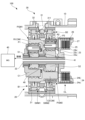
- FIG. 1 is a schematic diagram of a unit according to this embodiment.
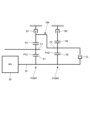
- FIG. 2 is a skeleton diagram of the unit.
- FIG. 3 is an enlarged view of the main part of the unit.
- FIG. 1 is a schematic diagram of a unit 100 according to this embodiment.
- FIG. 2 is a skeleton diagram of the unit 100.
- FIG. 3 is an enlarged view of the main parts of the unit 100.
- the unit can also be called, for example, a motor unit (a unit having at least a motor) or a power transmission device (a device having at least a power transmission mechanism).
- a motor is a rotating electric machine having an electric motor function and/or a generator function (at least one of an electric motor function and a generator function).
- a power transmission mechanism is, for example, a gear mechanism and/or a differential gear mechanism.
- a device (unit) having a motor and a power transmission mechanism is included in the concepts of both a motor unit and a power transmission device.
- the unit 100 includes a housing 10 and a transmission mechanism 20.
- the unit 100 is mounted on a vehicle, which is an electric vehicle. Power is input to the unit 100 from the MG 40.
- the MG 40 is a rotating electric machine that functions as a motor generator, and the unit 100 can also be understood as a configuration that further includes the MG 40.
- the housing 10 accommodates the transmission mechanism 20.
- the transmission mechanism 20 includes a case 21, a rotating shaft 22, a first planetary gear mechanism PGM1, a second planetary gear mechanism PGM2, a first brake B1, a second brake B2, and a clutch CL.
- the case 21 has a cylindrical shape and is fixed to the inner circumference of the housing 10.
- the first planetary gear mechanism PGM1 is provided in the case 21 via the first brake B1
- the second planetary gear mechanism PGM2 is provided in the case 21 via the second brake B2.
- the rotating shaft 22 is connected to MG4 and rotates by power from MG40.
- the extending direction of the rotating shaft 22 corresponds to the axial direction of the unit 100, and this axial direction means the axial direction of the rotating shaft of the component that constitutes the unit (for example, the motor, the gear mechanism, or the differential gear mechanism).
- the first planetary gear mechanism PGM1 comprises a first sun gear S1, a first carrier C1, a first ring gear R1, and a first pinion gear P1.
- the first sun gear S1 is fixed coaxially to the rotating shaft 22.
- the first carrier C1 supports the first pinion gear P1 for free rotation.
- the first pinion gear P1 meshes with both the first sun gear S1 and the first ring gear R1.
- the rotating shaft 22 passes through the inner circumference of the first sun gear S1 and the second sun gear S2, and the second planetary gear mechanism PGM2 is arranged side by side with the first planetary gear mechanism PGM1 in the axial direction. Therefore, the first planetary gear mechanism PGM1 has a portion that overlaps with the second planetary gear mechanism PGM2 when viewed in the axial direction.
- “Overlapping" when viewed in a specific direction, including radial and axial views, means overlapping in a specific direction, meaning that multiple elements are lined up in the specific direction. For this reason, when a drawing shows multiple elements lined up in a specific direction, it may be assumed that the specification contains a sentence explaining that multiple elements overlap when viewed in a specific direction.
- the second planetary gear mechanism PGM2 is provided on the side away from MG40 with respect to the first planetary gear mechanism PGM1.
- the rotating shaft 22 corresponds to a shaft.
- the first ring gear R1 and the second carrier C2 constitute a common member CM that rotates integrally.
- the first planetary gear mechanism PGM1 and the second planetary gear mechanism PGM2 have a common member CM in which the first ring gear R1 and the second carrier C2 rotate integrally.
- the first ring gear R1 and the second carrier C2 which are components of the common member CM, always rotate integrally during rotation.
- the first ring gear R1 and the second carrier C2 are integrally formed to be connected to each other and form the common member CM.
- the second carrier C2 constitutes the output element of the second planetary gear mechanism PGM2.
- the first carrier C1 constitutes the output element of the first planetary gear mechanism PGM1, and constitutes the output element of the entire first planetary gear mechanism PGM1 and the entire second planetary gear mechanism PGM2, thereby constituting the output element of the entire transmission mechanism 20.
- the first brake B1 is provided on the outer periphery of the first ring gear R1 and is connected to the first planetary gear mechanism PGM1.
- the second brake B2 is provided on the outer periphery of the second ring gear R2 and is connected to the second planetary gear mechanism PGM2. Therefore, the first brake B1 has a portion that overlaps with the first planetary gear mechanism PGM1 when viewed in the radial direction, and the second brake B2 has a portion that overlaps with the second planetary gear mechanism PGM2 when viewed in the radial direction.
- the first brake B1 and the second brake B2 are both meshing engagement elements and have a meshing fastening structure.
- the first brake B1 is fastened, the first ring gear R1 is fixed to the case 21 together with the second carrier C2.
- the first ring gear R1 is fixed to the housing 10 together with the second carrier C2.
- the common member CM is fixed to the housing 10.
- the second brake B2 is fastened, the second ring gear R2 is fixed to the case 21.
- the second ring gear R2 is fixed to the housing 10.
- the clutch CL is arranged axially alongside the second planetary gear mechanism PGM2 from the side away from MG40.
- the clutch CL is provided for the rotating shaft 22 and the second carrier C2, and connects and disconnects them.
- the clutch CL is a friction engagement element, and is a multi-plate clutch.
- the clutch CL is, for example, an electric clutch, and includes a hub 23, a drum 24, multiple drive plates 25, multiple driven plates 26, and a piston 27.
- the hub 23 is fixed coaxially to the rotating shaft 22.
- the hub 23 has an inner cylindrical portion 23a, an outer cylindrical portion 23b, and a bottom wall portion 23c connecting them, and is fixed coaxially to the rotating shaft 22 at the inner cylindrical portion 23a.
- the drum 24 has a cylindrical portion 24a and a bottom wall portion 24b, and is provided coaxially with the rotating shaft 22.
- the drum 24 opens in a direction away from the MG 40.
- the hub 23 is housed within the drum 24, and the outer periphery of the outer cylindrical portion 23b of the hub 23 faces the inner periphery of the cylindrical portion 24a of the drum 24.
- the drum 24 is fixedly connected to the second carrier C2 at the ring plate-shaped bottom wall portion 24b.
- the multiple drive plates 25 are provided on the hub 23.
- the multiple drive plates 25 are ring-shaped and are provided on the outer periphery of the outer cylindrical portion 23b so as to be slidable in the axial direction.
- the multiple driven plates 26 are provided on the drum 24.
- the multiple driven plates 26 are ring-shaped and are provided on the inner periphery of the cylindrical portion 24a so as to be slidable in the axial direction.
- the multiple drive plates 25 and the multiple driven plates 26 are arranged alternately one by one in the axial direction.
- the clutch CL When the multiple drive plates 25 and multiple driven plates 26 are pushed in the engagement direction by the piston 27 and engage, the clutch CL enters an engaged state. As a result, the rotating shaft 22 and the second carrier C2 are connected via the clutch CL. Also, when the piston 27 moves from this state in the disengagement direction and the multiple drive plates 25 and the multiple driven plates 26 are no longer engaged, the clutch CL enters a disengaged state. As a result, the connection between the rotating shaft 22 and the second carrier C2 via the clutch CL is cut off.
- the unit 100 further includes a drive device 30.
- the drive device 30 is a drive device for the first brake B1 and the second brake B2, and includes an actuator 31 and a worm wheel 32.
- the actuator 31 is shown diagrammatically by a two-dot dashed line.
- the actuator 31 is an electric motor and has a worm gear 311.
- the worm gear 311 constitutes the rotation axis of the actuator 31 and meshes with the worm wheel 32.
- the worm axis of the worm gear 311 and the central axis of the worm wheel 32 are perpendicular to each other, and the worm wheel 32 is arranged so that it can be rotated around the axis of the unit 100 by power from the actuator 31. Therefore, the longitudinal direction of the worm gear 311, which is the worm axis direction, intersects with the axial direction of the unit 100.
- the worm gear 311 and the worm wheel 32 are arranged between the first brake B1 and the second brake B2 in the axial direction of the unit 100, and have a portion sandwiched between the first brake B1 and the second brake B2.
- the first brake B1 is provided with a first switching mechanism SWM1
- the second brake B2 is provided with a second switching mechanism SWM2.
- Both the first switching mechanism SWM1 and the second switching mechanism SWM2 have a ring-shaped appearance.
- the first switching mechanism SWM1 has a portion that overlaps with the first brake B1 in the axial direction.
- the second switching mechanism SWM2 is provided in the second brake B2, and has a portion that overlaps with the second brake B2 in the axial direction.
- the first switching mechanism SWM1 switches the engagement state of the first brake B1, and the second switching mechanism SWM2 switches the engagement state of the second brake B2.
- the first switching mechanism SWM1 switches the engagement state of the first brake B1 between a bidirectional restriction state that restricts the rotation of the first ring gear R1 in both directions, a unidirectional restriction state that restricts the rotation in one direction, and a release state that does not restrict the rotation. The same is true for the second switching mechanism SWM2.
- the actuator 31 activates the first brake B1 by driving the first switching mechanism SWM1 via the worm gear 311 and the worm wheel 32. Similarly, the actuator 31 activates the second brake B2 by driving the second switching mechanism SWM2 via the worm gear 311 and the worm wheel 32.
- the first brake B1 and the second brake B2 correspond to the engagement elements, and the first switching mechanism SWM1 and the second switching mechanism SWM2 both correspond to the operating mechanisms.
- the unit 100 further includes a bearing 40 and an extension member 41.
- the bearing 40 is a radial needle bearing, and abuts against the rotating shaft 22 on the inner circumferential side.
- the bearing 40 is not limited to a bearing, and may be, for example, a bushing.
- the bearing 40 is provided between the common member CM and the rotating shaft 22 in the radial direction.
- the bearing 40 is disposed at an axial position where it radially overlaps with the first switching mechanism SWM1 and the second switching mechanism SWM2. In other words, the first switching mechanism SWM1 and the second switching mechanism SWM2 have portions that radially overlap with the bearing 40.
- the first switching mechanism SWM1 has a portion that overlaps with the first brake B1 in the axial direction
- the second switching mechanism SWM2 has a portion that overlaps with the second brake B2 in the axial direction. Therefore, the first switching mechanism SWM1 and the second switching mechanism SWM2, which are arranged to have a portion that overlaps with the bearing 40 in the radial direction, are arranged in a surplus space formed axially adjacent to the first brake B1 and the second brake B2.
- the surplus space can be utilized to provide the first switching mechanism SWM1 and the second switching mechanism SWM2, thereby realizing a layout of the unit 100 that contributes to reducing the axial dimension.
- the common member CM is supported on the rotating shaft 22 via the bearing 40 at a position (axial position) between the first sun gear S1 and the second sun gear S2. This can suppress rattling of the common member CM, thereby reducing the effect of the rattling of the unit 100, such as gear backlash and spline rattling, on the common member CM.
- the common member CM is supported via the bearing 40 at a well-balanced position in the axial direction, so rattling of the common member CM is suitably suppressed. As a result, the effect of the rattling of the unit 100 on the common member CM is further reduced.
- the common member CM is supported on the rotating shaft 22 via the bearing 40 via the extension member 41.
- the extension member 41 has a cylindrical shape and is interposed between the bearing 40 and the common member CM in the radial direction.
- the extension member 41 abuts against the bearing 40 on the inner circumferential side and is provided on the common member CM on the outer circumferential side.
- the extension member 41 has an extension portion 41a.
- the extension portion 41a is provided on the portion of the extension member 41 that is axially closer to the second gear mechanism PGM2, and has a brim-like shape.
- the radial gap formed by the extension member 41 and the common member CM in the portion axially closer to the first gear mechanism PGM1 than the extension portion 41a is used as an oil passage.
- the extension member 41 extends support radially from the rotating shaft 22 side to the inner diameter side of the common member CM.
- the extension portion 41a is fitted into the inlay portion E of the common member CM, whereby the common member CM is supported on the rotating shaft 22 via the bearing 40 and the extension member 41.
- Other shapes may be applied to the extension member 41, and the extension member 41 may be formed integrally with the common member CM.
- the extension member 41 it is possible to support the common member CM on the rotating shaft 22 via the bearing 40 without changing the common member CM, by extending support radially from the rotating shaft 22 side to the inner diameter side of the common member CM.
- by partially extending the extension member 41 further in the radial direction by the extension portion 41a it is also possible to ensure an oil passage.
- the rotating shaft 22 has a protrusion 22a.
- the protrusion 22a is a portion that protrudes in the radial direction, and is formed as an enlarged diameter portion that protrudes around the entire circumference. For example, multiple protrusions 22a may be provided partially in the circumferential direction.
- the protrusion 22a is arranged between the first sun gear S1 and the second sun gear S2 in the axial direction. Therefore, the rotating shaft 22 has the protrusion 22a that is sandwiched between the first sun gear S1 and the second sun gear S2 in the axial direction.
- the protrusions 22a regulate the axial positions of the first sun gear S1 and the second sun gear S2 at the stepped portions at both axial ends. Therefore, the protrusions 22a suppress both the axial shift of the first sun gear S1 toward the second sun gear S2 and the axial shift of the second sun gear S2 toward the first sun gear S1.
- the bearing 40 is disposed on the protrusion 22a, and the common member CM is supported on the protrusion 22a via the bearing 40.
- the rigidity of the rotating shaft 22 is increased at the protrusion 22a. Therefore, by disposing the bearing 40 on the protrusion 22a, the effect on the deflection of the rotating shaft 22 caused by supporting the common member CM on the rotating shaft 22 via the bearing 40 is reduced.
- the unit 100 has a first planetary gear mechanism PGM1 having a first sun gear S1, a first carrier C1, and a first ring gear R1, a second planetary gear mechanism PGM2 having a second sun gear S2, a second carrier C2, and a second ring gear R2, and a rotating shaft 22 passing through the inner circumference of the first sun gear S1 and the second sun gear S2.
- the first planetary gear mechanism PGM1 and the second planetary gear mechanism PGM2 have a common member CM in which the first ring gear R1, which is one of the first carrier C1 and the first ring gear R1, and the second carrier C2, which is one of the second carrier C2 and the second ring gear R2, rotate together.
- the common member CM is supported by the rotating shaft 22 via a bearing 40.
- the common member CM is supported on the rotating shaft 22 via the bearing 40.
- the common member CM is supported by providing support between the rotating shaft 22 and the common member CM in the radial direction, such as by extending the support radially from the rotating shaft 22 side to the inner diameter side of the common member CM. This makes it possible to suppress wobbling of the common member CM, thereby reducing the effect of the wobble of the unit 100 on the common member CM.
- the common member CM can be supported via the bearing 40 at a position that is well balanced in the axial direction, so that wobble of the common member CM is suitably suppressed, thereby further reducing the effect of the wobble of the unit 100 on the common member CM.
- the rotating shaft 22 has a protrusion 22a that is sandwiched between the first sun gear S1 and the second sun gear S2 in the axial direction.
- the common member CM is supported by the protrusion 22a via a bearing 40.
- the protrusion 22a can suppress axial misalignment of the first sun gear S1 and the second sun gear S2.
- the protrusion 22a which increases the rigidity of the rotating shaft 22, supports the common member CM via the bearing 40, reducing the effect on the deflection of the rotating shaft 22 caused by supporting the common member CM on the rotating shaft 22 via the bearing 40.
- the unit 100 further includes a first brake B1 connected to the first planetary gear mechanism PGM1, a second brake B2 connected to the second planetary gear mechanism PGM2, and a first switching mechanism SWM1 and a second switching mechanism SWM2 that operate the first brake B1 and the second brake B2.
- the first switching mechanism SWM1 and the second switching mechanism SWM2 have portions that radially overlap the bearing 40.
- the first switching mechanism SWM1 and the second switching mechanism SWM2 can be provided using the extra space formed axially adjacent to the first brake B1 and the second brake B2, making it possible to realize a layout of the unit 100 that contributes to reducing the axial dimension.
- the first ring gear R1 and the second carrier C2 are described as the common member CM.
- the common member CM may be the first carrier C1 and the second ring gear R2, the first carrier C1 and the second carrier C2, or the first ring gear R1 and the second ring gear R2.
- the unit 100 may have either the first brake B1 or the second brake B2 as an engagement element. Even in this case, the first switching mechanism SWM1 or the second switching mechanism SWM2 can be provided by utilizing the extra space formed axially adjacent to either the first brake B1 or the second brake B2, so that a layout of the unit 100 that contributes to reducing the axial dimension can be realized.
Landscapes
- Engineering & Computer Science (AREA)
- General Engineering & Computer Science (AREA)
- Mechanical Engineering (AREA)
- Structure Of Transmissions (AREA)
- Retarders (AREA)
- General Details Of Gearings (AREA)
Priority Applications (3)
| Application Number | Priority Date | Filing Date | Title |
|---|---|---|---|
| CN202380091941.8A CN120569579A (zh) | 2023-01-30 | 2023-11-27 | 单元 |
| EP23919903.7A EP4660481A1 (en) | 2023-01-30 | 2023-11-27 | Unit |
| JP2024574281A JP7825081B2 (ja) | 2023-01-30 | 2023-11-27 | ユニット |
Applications Claiming Priority (2)
| Application Number | Priority Date | Filing Date | Title |
|---|---|---|---|
| JP2023011959 | 2023-01-30 | ||
| JP2023-011959 | 2023-01-30 |
Publications (1)
| Publication Number | Publication Date |
|---|---|
| WO2024161768A1 true WO2024161768A1 (ja) | 2024-08-08 |
Family
ID=92146298
Family Applications (1)
| Application Number | Title | Priority Date | Filing Date |
|---|---|---|---|
| PCT/JP2023/042324 Ceased WO2024161768A1 (ja) | 2023-01-30 | 2023-11-27 | ユニット |
Country Status (4)
| Country | Link |
|---|---|
| EP (1) | EP4660481A1 (https=) |
| JP (1) | JP7825081B2 (https=) |
| CN (1) | CN120569579A (https=) |
| WO (1) | WO2024161768A1 (https=) |
Citations (8)
| Publication number | Priority date | Publication date | Assignee | Title |
|---|---|---|---|---|
| JPH0565946A (ja) * | 1991-09-05 | 1993-03-19 | Bridgestone Cycle Co | 変速装置 |
| JP2000193049A (ja) * | 1998-12-25 | 2000-07-14 | Unitec:Kk | 歯車変速装置 |
| DE102007033417A1 (de) * | 2007-07-18 | 2009-01-22 | Schaeffler Kg | Planetenradgetriebe |
| CN101956793A (zh) * | 2009-07-20 | 2011-01-26 | 中国北方车辆研究所 | 用于自动变速箱的六前三倒行星变速器 |
| JP2013526689A (ja) * | 2010-05-17 | 2013-06-24 | ディーティーアイ グループ ビー.ブイ. | 電気又はハイブリッド駆動機構用の変速装置 |
| US20150158382A1 (en) * | 2013-12-05 | 2015-06-11 | Avl Powertrain Engineering, Inc. | Two-speed transmission for electric vehicle |
| CN105443707A (zh) | 2016-01-22 | 2016-03-30 | 吉林大学 | 一种基于两挡变速器的电驱动装置 |
| CN112747088A (zh) * | 2019-10-29 | 2021-05-04 | 中车时代电动汽车股份有限公司 | 新能源汽车及其变速器和齿轮传动结构 |
-
2023
- 2023-11-27 CN CN202380091941.8A patent/CN120569579A/zh active Pending
- 2023-11-27 EP EP23919903.7A patent/EP4660481A1/en active Pending
- 2023-11-27 WO PCT/JP2023/042324 patent/WO2024161768A1/ja not_active Ceased
- 2023-11-27 JP JP2024574281A patent/JP7825081B2/ja active Active
Patent Citations (8)
| Publication number | Priority date | Publication date | Assignee | Title |
|---|---|---|---|---|
| JPH0565946A (ja) * | 1991-09-05 | 1993-03-19 | Bridgestone Cycle Co | 変速装置 |
| JP2000193049A (ja) * | 1998-12-25 | 2000-07-14 | Unitec:Kk | 歯車変速装置 |
| DE102007033417A1 (de) * | 2007-07-18 | 2009-01-22 | Schaeffler Kg | Planetenradgetriebe |
| CN101956793A (zh) * | 2009-07-20 | 2011-01-26 | 中国北方车辆研究所 | 用于自动变速箱的六前三倒行星变速器 |
| JP2013526689A (ja) * | 2010-05-17 | 2013-06-24 | ディーティーアイ グループ ビー.ブイ. | 電気又はハイブリッド駆動機構用の変速装置 |
| US20150158382A1 (en) * | 2013-12-05 | 2015-06-11 | Avl Powertrain Engineering, Inc. | Two-speed transmission for electric vehicle |
| CN105443707A (zh) | 2016-01-22 | 2016-03-30 | 吉林大学 | 一种基于两挡变速器的电驱动装置 |
| CN112747088A (zh) * | 2019-10-29 | 2021-05-04 | 中车时代电动汽车股份有限公司 | 新能源汽车及其变速器和齿轮传动结构 |
Non-Patent Citations (1)
| Title |
|---|
| See also references of EP4660481A1 |
Also Published As
| Publication number | Publication date |
|---|---|
| JP7825081B2 (ja) | 2026-03-05 |
| EP4660481A1 (en) | 2025-12-10 |
| CN120569579A (zh) | 2025-08-29 |
| JPWO2024161768A1 (https=) | 2024-08-08 |
Similar Documents
| Publication | Publication Date | Title |
|---|---|---|
| JP4708467B2 (ja) | 車両の駆動装置 | |
| JP6911782B2 (ja) | 動力伝達装置 | |
| JP5842998B2 (ja) | 車両用変速機 | |
| CN108953499B (zh) | 齿轮传动装置 | |
| WO2011034191A9 (ja) | ハイブリッド駆動装置 | |
| WO2020105635A1 (ja) | 車両用駆動装置 | |
| JP2019143708A (ja) | 自動変速機 | |
| JP5445506B2 (ja) | 変速装置 | |
| WO2020183816A1 (ja) | 動力伝達装置 | |
| JP5489954B2 (ja) | 車両用駆動装置 | |
| WO2015105165A1 (ja) | 自動変速機 | |
| JP5440543B2 (ja) | 変速装置 | |
| JP7825081B2 (ja) | ユニット | |
| CN108138953A (zh) | 用于机动车的切换装置和驱动单元 | |
| JP7387956B2 (ja) | 動力伝達装置 | |
| JP2019074207A (ja) | 車両用駆動装置 | |
| JP7780657B2 (ja) | ユニット | |
| JP7566449B2 (ja) | 装置 | |
| JP4231963B2 (ja) | 自動変速機の動力伝達装置 | |
| JP2020143780A (ja) | 動力伝達装置 | |
| JP2020101224A (ja) | 動力伝達装置 | |
| JP2890458B2 (ja) | 遊星歯車式変速装置の回転軸支持構造 | |
| JP7400154B2 (ja) | 動力伝達装置 | |
| WO2024014130A1 (ja) | ユニット | |
| JP2023028035A (ja) | 車両の走行モード切替え装置 |
Legal Events
| Date | Code | Title | Description |
|---|---|---|---|
| 121 | Ep: the epo has been informed by wipo that ep was designated in this application |
Ref document number: 23919903 Country of ref document: EP Kind code of ref document: A1 |
|
| WWE | Wipo information: entry into national phase |
Ref document number: 2024574281 Country of ref document: JP |
|
| WWE | Wipo information: entry into national phase |
Ref document number: 202380091941.8 Country of ref document: CN |
|
| WWP | Wipo information: published in national office |
Ref document number: 202380091941.8 Country of ref document: CN |
|
| NENP | Non-entry into the national phase |
Ref country code: DE |
|
| WWP | Wipo information: published in national office |
Ref document number: 2023919903 Country of ref document: EP |