WO2024161543A1 - 絶縁電線および樹脂組成物 - Google Patents
絶縁電線および樹脂組成物 Download PDFInfo
- Publication number
- WO2024161543A1 WO2024161543A1 PCT/JP2023/003212 JP2023003212W WO2024161543A1 WO 2024161543 A1 WO2024161543 A1 WO 2024161543A1 JP 2023003212 W JP2023003212 W JP 2023003212W WO 2024161543 A1 WO2024161543 A1 WO 2024161543A1
- Authority
- WO
- WIPO (PCT)
- Prior art keywords
- mass
- nitrogen
- resin
- containing organic
- organic compound
- Prior art date
- Legal status (The legal status is an assumption and is not a legal conclusion. Google has not performed a legal analysis and makes no representation as to the accuracy of the status listed.)
- Ceased
Links
Images
Classifications
-
- H—ELECTRICITY
- H01—ELECTRIC ELEMENTS
- H01B—CABLES; CONDUCTORS; INSULATORS; SELECTION OF MATERIALS FOR THEIR CONDUCTIVE, INSULATING OR DIELECTRIC PROPERTIES
- H01B7/00—Insulated conductors or cables characterised by their form
- H01B7/02—Disposition of insulation
Definitions
- This disclosure relates to an insulated wire and a resin composition.
- Patent Document 1 Electronic devices (insulated wires, etc.) that have a conductor and a coating that covers the conductor have been used in motors, transformers, etc.
- Patent Document 2 Patent Document 2
- resin compositions that contain an adhesion additive and a resin have been used in electronic devices (Patent Document 3).
- the insulated wire of the present disclosure comprises: An insulated wire comprising a conductor and a coating covering the conductor, The coating includes an adhesion layer in contact with the conductor and an insulating layer formed on the adhesion layer,
- the adhesion layer includes a nitrogen-containing organic compound and a first resin,
- the insulating layer includes a second resin, the first resin and the second resin are each at least one selected from the group consisting of polyimide and polyamideimide;
- the ratio of the total atomic weight of nitrogen atoms constituting the nitrogen-containing organic compound to the molecular weight of the nitrogen-containing organic compound is 60% or more.
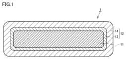
- FIG. 1 is a schematic cross-sectional (transverse) view illustrating one embodiment of an insulated electric wire according to the present disclosure.
- the present disclosure therefore aims to provide an insulated electric wire that has excellent adhesion between the conductor and the coating, even when manufactured under manufacturing conditions for an insulated electric wire with a high wire speed.
- the insulated wire of the present disclosure has An insulated wire comprising a conductor and a coating covering the conductor, the coating includes an adhesive layer in contact with the conductor and an insulating layer formed on the adhesive layer,
- the adhesion layer includes a nitrogen-containing organic compound and a first resin,
- the insulating layer includes a second resin, the first resin and the second resin are each at least one selected from the group consisting of polyimide and polyamideimide;
- the ratio of the total atomic weight of nitrogen atoms constituting the nitrogen-containing organic compound to the molecular weight of the nitrogen-containing organic compound is 60% or more.
- an insulated electric wire that has excellent adhesion between the conductor and the coating, even when the wire is manufactured under manufacturing conditions that require a high wire speed.
- the content of the nitrogen-containing organic compound is preferably 0.010% by mass or more and 5.0% by mass or less with respect to the adhesion layer. This makes it possible to provide an insulated electric wire having excellent adhesion between the conductor and the coating, even when the insulated electric wire is manufactured under manufacturing conditions for a high wire speed.
- the nitrogen-containing organic compound does not have a 1,3,5-triazine ring structure. This makes it possible to provide an insulated electric wire with superior adhesion between the conductor and the coating, even when the wire is manufactured under manufacturing conditions for an insulated electric wire with a high wire speed.
- the polyimide is a polymer of a tetracarboxylic dianhydride and a diamine compound
- the tetracarboxylic dianhydride is either one or both of pyromellitic dianhydride and 3,3',4,4'-biphenyltetracarboxylic dianhydride
- the diamine compound is preferably 4,4'-diaminodiphenyl ether, which makes it possible to provide an insulated electric wire having excellent adhesion between the conductor and the coating even when the insulated electric wire is produced under production conditions for a high drawing speed.
- the polyamide-imide is a polymer of a tricarboxylic acid anhydride and a diisocyanate compound
- the tricarboxylic acid anhydride is trimellitic anhydride
- the diisocyanate compound is preferably diphenylmethane diisocyanate, which makes it possible to provide an insulated electric wire having excellent adhesion between the conductor and the coating even when the insulated electric wire is produced under production conditions for a high drawing speed.
- the resin composition of the present disclosure is A resin composition comprising a nitrogen-containing organic compound, a solvent, and one or more members selected from the group consisting of polyamic acid and polyamideimide,
- the ratio of the total atomic weight of nitrogen atoms constituting the nitrogen-containing organic compound to the molecular weight of the nitrogen-containing organic compound is 60% or more.
- the resin composition disclosed herein can provide an insulated electric wire that has excellent adhesion between the conductor and the coating, even when the wire is manufactured under manufacturing conditions for an insulated electric wire with a high wire drawing speed.
- a ⁇ B means the upper and lower limits of a range (i.e., greater than or equal to A and less than or equal to B). If no unit is stated for A and only a unit is stated for B, the units of A and B are the same.
- An insulated wire according to an embodiment of the present disclosure will be described with reference to FIG. 1 .
- One embodiment of the present disclosure (hereinafter also referred to as “the present embodiment") is An insulated wire 1 including a conductor 11 and a coating 12 that covers the conductor 11,
- the coating 12 includes an adhesive layer 13 in contact with the conductor 11 and an insulating layer 14 formed on the adhesive layer 13,
- the adhesion layer 13 includes a nitrogen-containing organic compound and a first resin
- the insulating layer 14 includes a second resin, the first resin and the second resin are each at least one selected from the group consisting of polyimide and polyamideimide;
- the ratio of the total atomic weight of nitrogen atoms constituting the nitrogen-containing organic compound to the molecular weight of the nitrogen-containing organic compound is 60% or more.
- the adhesion between the conductor 11 and the adhesive layer 13 is enhanced by an ionic bond reaction between the conductor 11 (cation) and the adhesion additive (anion).
- the ionic bond reaction requires a certain amount of heat.
- the amount of heat required for the ionic bond reaction tends to be insufficient.
- the coating 12 includes an adhesive layer 13 in contact with the conductor 11 and an insulating layer 14 formed on the adhesive layer 13,
- the adhesion layer 13 includes a nitrogen-containing organic compound and a first resin,
- the ratio of the total atomic weight of the nitrogen atoms constituting the nitrogen-containing organic compound to the molecular weight of the nitrogen-containing organic compound is 60% or more.
- the nitrogen-containing organic compound has excellent stability when bonded to the metal constituting the conductor 11, and therefore can proceed with an ionic bond reaction between the conductor 11 and the adhesion additive (the nitrogen-containing organic compound) even with a low amount of heat. Therefore, the insulated wire 1 having the coating 12 including such an adhesion layer 13 can have excellent adhesion between the conductor 11 and the coating 12 even when manufactured under manufacturing conditions for the insulated wire 1 with a high linear speed.
- the insulated wire 1 has a linear shape.
- the cross-sectional shape of the insulated wire 1 may be a circle (including an approximately circular shape), an ellipse, or a rectangular shape.
- the cross-sectional shape of the insulated wire 1 refers to a cross section that appears by cutting the insulated wire 1 along a plane perpendicular to the longitudinal direction.
- a "rectangular shape,” which is one of the cross-sectional shapes of the insulated wire 1, includes a rectangle and a square, and also includes shapes in which the four corners of the rectangle and square are chamfered or have a rounded shape (R shape).
- coating the conductor 11 here means that it is preferable to coat the entire surface of the conductor 11, but as long as the effects of this disclosure are exhibited, it does not depart from the scope of this disclosure even if only a portion of the surface of the conductor 11 is not covered by the coating 12.
- the insulated wire 1 includes a conductor 11 (FIG. 1).
- the conductor 11 means an electrical conductor.
- the material of the conductor 11 is preferably a metal having high electrical conductivity and high mechanical strength. Specific examples include copper, copper alloy, aluminum, aluminum alloy, nickel, silver, soft iron, steel, and stainless steel.
- the conductor may be a wire formed from these metals in a linear shape, a coated wire in which the surface of the wire is coated with another metal, or a twisted wire in which a plurality of wires are twisted together. Examples of the coated wire include nickel-coated copper wire, silver-coated copper wire, silver-coated aluminum wire, and copper-coated steel wire, but are not limited thereto.
- the shape of the conductor 11 is not particularly limited, and a round wire, a square wire, etc. can be appropriately selected depending on the intended use and electrical characteristics of the insulated electric wire 1.
- the cross-sectional shape of the conductor 11 may be a circle (including an approximate circle) or a rectangular shape.
- the cross-section of the conductor 11 means a cross-section that appears when the conductor is cut along a plane perpendicular to the longitudinal direction of the conductor.
- the diameter or outer periphery of the conductor 11 is not particularly limited, and can be appropriately selected depending on the intended use and electrical characteristics of the insulated electric wire.
- the insulated wire 1 includes a coating 12 that covers the conductor 11 ( FIG. 1 ).
- the thickness of the coating 12 is preferably 5 ⁇ m or more and 500 ⁇ m or less. If the thickness of the coating 12 is less than 5 ⁇ m or more, the coating 12 tends to be easily damaged, and the insulating properties of the coating 12 may be insufficient. If the thickness of the coating 12 exceeds 500 ⁇ m or less, the volume efficiency of a coil or the like formed using the insulated wire 1 tends to be low.
- the thickness of the coating 12 means the average value of the thickness of the coating 12 in the cross section of the insulated electric wire 1.
- the measurement method will be described in more detail below. Specifically, first, a scanning electron microscope (SEM) is used to obtain microscopic images of five arbitrary cross sections of the insulated electric wire. Next, five arbitrary points are selected on the outer periphery (outermost surface) of the insulated electric wire 1 in each of the above microscopic images, and the shortest distance from the outer periphery to the conductor 11 at each point is determined, and this is taken as the thickness of the coating 12. The thickness of the coating 12 is measured at a total of 25 points, and an average value is calculated from the values obtained, and this can be taken as the thickness of the coating 12. If there are obvious abnormal values in the above measurements, the abnormal values are excluded and the average value is calculated. If there are three or more abnormal values, the same number of measurements are performed as alternatives, and the average value is calculated using the values obtained thereby.
- SEM scanning electron microscope
- the coating 12 includes an adhesion layer 13 in contact with the conductor 11 ( FIG. 1 ).
- the adhesion layer 13 includes a nitrogen-containing organic compound and a first resin.
- “including a nitrogen-containing organic compound and a first resin” means that the adhesion layer 13 may be composed of the nitrogen-containing organic compound and the first resin, or may further include, as components other than the nitrogen-containing organic compound and the first resin, for example, a filler, a curing agent, other additives, "a resin other than the first resin", etc.
- the ratio of the total atomic weight of the nitrogen atoms constituting the nitrogen-containing organic compound to the molecular weight of the nitrogen-containing organic compound is 60% or more. This allows the adhesion additive (the conductor 11) to be bonded to the nitrogen-containing organic compound even with a low amount of heat. Since the ionic bond reaction with the insulated electric wire (nitrogen-containing organic compound) can proceed, excellent adhesion between the conductor 11 and the coating 12 can be achieved even when the insulated electric wire 1 is manufactured under manufacturing conditions with a high drawing speed.
- the lower limit of the ratio is preferably 61% or more, more preferably 65% or more, and even more preferably 70% or more.
- the ratio is preferably 61% or more and 83% or less, and even more preferably 70% or more and 82% or less. It is more preferable that the content is 70% or more and 81% or less, and further more preferable that the content is 70% or more and 81% or less.
- the ratio in the adhesion layer 13 can be determined by the following method. That is, first, an arbitrary cross section is obtained for the insulated electric wire. Next, an analysis such as TOF-SIMS is performed on the region of the adhesion layer in the cross section to identify the structure of the nitrogen-containing organic compound, and to determine the molecular weight of the nitrogen-containing organic compound and the number of nitrogen atoms in one molecule of the nitrogen-containing organic compound. Next, the product of the number of nitrogen atoms and the atomic weight of the nitrogen atom (14.01) is divided by the molecular weight of the nitrogen-containing organic compound to obtain a value, and the ratio is determined by multiplying the value by 100. Note that it has been confirmed that there is no variation in the measurement results even if the measurement location is arbitrarily selected, as long as the measurement is performed on the same insulated electric wire.
- the nitrogen-containing organic compound preferably does not have a 1,3,5-triazine ring structure. This makes it possible to prevent inactivation due to self-aggregation of compounds derived from the triazine ring structure, and therefore makes it possible to provide an insulated electric wire 1 that has better adhesion between the conductor 11 and the coating 12, even when the insulated electric wire 1 is manufactured under manufacturing conditions that result in a high drawing speed.
- the fact that the nitrogen-containing organic compound in the adhesion layer 13 does not have a 1,3,5-triazine ring structure can be determined by the following method. That is, first, an arbitrary cross section is obtained for the insulated wire. Next, an analysis such as TOF-SIMS is performed on the region of the adhesion layer in the cross section to identify the structure of the nitrogen-containing organic compound and determine whether or not the nitrogen-containing organic compound has a triazine ring structure. It has been confirmed that there is no variation in the measurement results even if the measurement location is arbitrarily selected, as long as the measurement is performed on the same insulated wire.
- the nitrogen-containing organic compound preferably does not contain elemental sulfur. This prevents corrosion of the conductor metal caused by elemental sulfur, making it possible to provide an insulated electric wire 1 that has better adhesion between the conductor 11 and the coating 12 even when the insulated electric wire 1 is manufactured under manufacturing conditions that result in a high drawing speed.
- the fact that the nitrogen-containing organic compound in the adhesion layer 13 does not contain elemental sulfur can be determined by the following method. That is, first, an arbitrary cross section is obtained for the insulated electric wire. Next, an analysis such as TOF-SIMS is performed on the region of the adhesion layer in the cross section to identify the structure of the nitrogen-containing organic compound and to determine whether or not the nitrogen-containing organic compound contains elemental sulfur. It has been confirmed that, as long as measurements are taken on the same insulated electric wire, there is no variation in the measurement results even if the measurement location is arbitrarily selected.
- the nitrogen-containing organic compound examples include 5-aminotetrazole, tetrazole, aminoguanidine, 3,5-diamino-1,2,4-triazole, dicyandiamide, 3-amino-1,2,4-triazole, melamine, and 1,2,4-triazole. Since the nitrogen-containing organic compound does not have a 1,3,5-triazine ring structure, it is particularly preferable that the nitrogen-containing organic compound is at least one type of nitrogen-containing organic compound selected from the group consisting of 5-aminotetrazole, tetrazole, aminoguanidine, diaminotriazole, dicyandiamide, and aminotriazole.
- the content of the nitrogen-containing organic compound is preferably 0.010% by mass or more and 5.0% by mass or less with respect to the adhesive layer 13. This makes it easier to ensure a sufficient content of the nitrogen-containing organic compound for adhesion between the conductor 11 and the adhesive layer 13 near the interface with the conductor 11, so that even when the insulated electric wire is manufactured under manufacturing conditions for a high linear speed, the conductor 11 and the coating 12 can have better adhesion.
- the lower limit of the content of the nitrogen-containing organic compound is preferably 0.010% by mass or more with respect to the adhesive layer 13, more preferably 0.05% by mass or more, and even more preferably 0.10% by mass or more.
- the upper limit of the content of the nitrogen-containing organic compound is preferably 5.0% by mass or less with respect to the adhesive layer 13, more preferably 4.5% by mass or less, and even more preferably 4.0% by mass or less. Furthermore, the content of the nitrogen-containing organic compound is more preferably 0.05% by mass or more and 4.5% by mass or less, and even more preferably 0.10% by mass or more and 4.0% by mass or less, relative to the adhesion layer 13.
- the content of the nitrogen-containing organic compound in the adhesive layer 13 can be specified by the following method. First, the adhesive layer 13 is removed from the coating 12 of the insulated wire 1. The mass of the adhesive layer 13 is then measured. The adhesive layer 13 is freeze-pulverized to obtain a sample. The sample is then added to a solvent described below and shaken at room temperature for 24 hours to obtain a sample after shaking and an extract. The extract is then filtered to obtain a filtrate. The filtrate is then subjected to LC/MS (Liquid Chromatography-Mass Spectrometry) measurement under the following conditions to measure the amount of the nitrogen-containing organic compound extracted.
- LC/MS Liquid Chromatography-Mass Spectrometry
- the solvents used are dimethylformamide, tetrahydrofuran, methanol, and water, and the content of the nitrogen-containing organic compound can be determined by calculating the ratio of the highest amount of extraction to the mass of the adhesive layer 13 as a percentage.
- the content can be determined by the following method. First, the coating 12 is removed from the insulated wire 1. The mass of the coating 12 is then measured. The amount of nitrogen-containing organic compounds extracted from the coating 12 is measured by the same method as above, except that the sample is obtained by freeze-pulverizing the coating 12.
- the mass ratio of the adhesive layer 13 to the coating 12 is determined by observing the cross section of the insulated wire 1 using a SEM, and calculating the ratio of the area of the adhesive layer 13 to the area of the cross section using image processing software ("Winroof" manufactured by Mitani Shoji Co., Ltd.). The mass of the adhesive layer 13 in the coating 12 is then multiplied by the ratio to the mass of the adhesive layer 13. The amount of nitrogen-containing organic compounds extracted from the adhesive layer 13 in the coating 12 is then calculated as a percentage, so that the content of the nitrogen-containing organic compounds in the adhesive layer 13 can be determined.
- the first resin is at least one selected from the group consisting of polyimide and polyamideimide.
- the polyimide refers to a polymer having an imide bond (-CONCO-) in the main chain.
- the polyamideimide refers to a polymer having an amide bond and an imide bond in the molecule.
- the polyimide is a polymer of a tetracarboxylic dianhydride and a diamine compound, and the polyimide preferably contains at least one of a structural unit derived from pyromellitic dianhydride and a structural unit derived from 3,3',4,4'-biphenyltetracarboxylic dianhydride, and preferably contains a structural unit derived from 4,4'-diaminodiphenyl ether.
- the tetracarboxylic dianhydride is either one or both of pyromellitic dianhydride and 3,3',4,4'-biphenyltetracarboxylic dianhydride, and that the diamine compound is 4,4'-diaminodiphenyl ether. This provides better adhesion between the conductor 11 and the adhesive layer 13 (in other words, between the conductor 11 and the coating 12).
- the polyamide-imide is a polymer of a tricarboxylic anhydride and a diisocyanate compound, and the tricarboxylic anhydride is preferably trimellitic anhydride, and the diisocyanate compound is preferably diphenylmethane diisocyanate. This provides better adhesion between the conductor 11 and the adhesive layer 13 (in other words, between the conductor 11 and the coating 12).
- the weight average molecular weight of the first resin is preferably 5,000 or more and 100,000 or less. This makes it possible to ensure both the mechanical strength of the adhesion layer 13 and the applicability of the resin varnish used in forming the adhesion layer 13.
- mechanical strength refers to the resistance of the adhesion layer 13 to breakage caused by bending the insulated electric wire 1.
- the weight average molecular weight of the first resin is more preferably 20,000 or more and 90,000 or less, and even more preferably 40,000 or more and 80,000 or less.
- the weight average molecular weight of the first resin in the adhesion layer 13 can be determined by measuring it using gel permeation chromatography (GPC) in accordance with JIS-K7252-1:2008 "Plastics - Determination of average molecular weight and molecular weight distribution of polymers by size exclusion chromatography - Part 1: General rules.”
- GPC gel permeation chromatography
- the content of the first resin is preferably 50% by mass or more and 100% by mass or less with respect to the adhesion layer 13. This allows for better adhesion between the conductor 11 and the adhesion layer 13 (in other words, between the conductor 11 and the coating 12).
- the content of the first resin is more preferably 65% by mass or more and 100% by mass or less with respect to the adhesion layer 13, and even more preferably 80% by mass or more and 100% by mass or less.
- the content [mass %] of the first resin in the adhesion layer 13 can be determined by the following method. That is, the content [mass %] of the first resin in the adhesion layer 13 can be determined by performing a composition analysis, such as NMR measurement after chemical decomposition, on the adhesion layer 13.
- Filler examples include silica particles, alumina particles, talc particles, and boron nitride particles.
- the curing agent has a function of curing the resin.
- Specific examples thereof include imidazole, triethylamine, titanium compounds, isocyanate compounds, blocked isocyanates, urea, melamine compounds, acetylene derivatives, alicyclic acid anhydrides such as methyltetrahydrophthalic anhydride, aliphatic acid anhydrides, and aromatic acid anhydrides.
- the titanium compounds include tetrapropyl titanate, tetraisopropyl titanate, tetramethyl titanate, tetrabutyl titanate, and tetrahexyl titanate.
- isocyanate compounds include aromatic diisocyanates such as tolylene diisocyanate (TDI), diphenylmethane diisocyanate (MDI), p-phenylene diisocyanate, and naphthalene diisocyanate; aliphatic diisocyanates having 3 to 12 carbon atoms such as hexamethylene diisocyanate (HDI), 2,2,4-trimethylhexane diisocyanate, and lysine diisocyanate; 1,4-cyclohexane diisocyanate (CDI), isophorone diisocyanate (IPDI), 4,4'-dicyclohexylmethane diisocyanate (hydrogenated MDI), and methyl diisocyanates.
- aromatic diisocyanates such as tolylene diisocyanate (TDI), diphenylmethane diisocyanate (MDI), p-phenylene diisocyanate, and naphthalene diiso
- isocyanate examples include alicyclic isocyanates having 5 to 18 carbon atoms, such as tetramethylcyclohexane diisocyanate, isopropylidenedicyclohexyl-4,4'-diisocyanate, 1,3-diisocyanatomethylcyclohexane (hydrogenated XDI), hydrogenated TDI, 2,5-bis(isocyanatomethyl)-bicyclo[2,2,1]heptane, and 2,6-bis(isocyanatomethyl)-bicyclo[2,2,1]heptane; aliphatic diisocyanates having an aromatic ring, such as xylylene diisocyanate (XDI) and tetramethylxylylene diisocyanate (TMXDI); and modified products thereof.
- XDI xylylene diisocyanate
- TMXDI tetramethylxylylene diisocyanate
- blocked isocyanate examples include diphenylmethane-4,4'-diisocyanate (MDI), diphenylmethane-3,3'-diisocyanate, diphenylmethane-3,4'-diisocyanate, diphenylether-4,4'-diisocyanate, benzophenone-4,4'-diisocyanate, diphenylsulfone-4,4'-diisocyanate, tolylene-2,4-diisocyanate, tolylene-2,6-diisocyanate, naphthylene-1,5-diisocyanate, m-xylylene diisocyanate, p-xylylene diisocyanate, etc.
- MDI diphenylmethane-4,4'-diisocyanate
- diphenylmethane-3,3'-diisocyanate diphenylmethane-3,4'-diisocyanate
- Examples of the melamine compound include methylated melamine, butylated melamine, methylolated melamine, butyrolated melamine, etc.
- Examples of the acetylene derivative include ethynylaniline, ethynylphthalic anhydride, etc.
- antioxidants examples include antioxidants, ultraviolet inhibitors, and lubricant-imparting agents.
- Resins other than the first resin examples include polyvinyl formal, thermosetting polyurethane, thermosetting acrylic, epoxy, thermosetting polyester, thermosetting polyesterimide, thermosetting polyesteramideimide, aromatic polyamide, polyphenylsulfone, polyphenylene sulfide, polyetherimide, polyetheretherketone, polyethersulfone, and thermally decomposable resins.
- the thickness of the adhesion layer 13 is preferably 1 ⁇ m or more and 20 ⁇ m or less. If the thickness of the adhesion layer 13 is less than 1 ⁇ m, the adhesion layer 13 is too thin and there is a risk that sufficient adhesion cannot be obtained. If the thickness of the adhesion layer 13 is more than 20 ⁇ m or less, the residual stress in the adhesion layer 13 becomes large, and there is a risk that the adhesion layer 13 is easily peeled off from the conductor 11.
- the thickness of the adhesion layer 13 means the average value of the thickness of the adhesion layer 13 covering two pairs of opposite surfaces (upper, lower, left and right surfaces) of the outer periphery of the conductor 11 in a cross section obtained by cutting the insulated electric wire 1 in a plane perpendicular to its longitudinal direction. Specifically, the cross section obtained by cutting the insulated electric wire 1 in a plane perpendicular to its longitudinal direction is first polished to prepare a measurement surface. Next, the measurement surface is photographed using a digital microscope VHX-7000 (manufactured by Keyence Corporation) to obtain an image.
- the thickness of the adhesion layer 13 covering two pairs of opposite surfaces of the outer periphery of the conductor 11 in the image is determined by, for example, selecting one location each from the upper, lower, left and right surfaces of the conductor 11, measuring the thickness of the adhesion layer 13 at these four locations, and calculating the average value from the values obtained, which can be used as the thickness of the adhesion layer 13.
- the coating 12 includes an insulating layer 14 formed on the adhesive layer 13 (FIG. 1).
- the insulating layer 14 includes a second resin.
- “including the second resin” means that the insulating layer 14 may further include, as a component other than the second resin, for example, the filler, the curing agent, the other additives, "a resin other than the second resin", etc.
- “including the insulating layer 14 formed on the adhesive layer 13” is a concept that includes both the case where the insulating layer 14 and the adhesive layer 13 are in contact with each other (FIG. 1) and the case where the insulating layer 14 and the adhesive layer 13 are not in contact with each other (not shown).
- the coating 12 may further include an "intermediate layer"("otherlayer") located between the insulating layer 14 and the adhesive layer 13.
- the second resin is at least one selected from the group consisting of polyimide and polyamideimide.
- Polyimide is a polymer having an imide bond (-CONCO-) in the main chain.
- Polyamideimide is a polymer having an amide bond and an imide bond in the molecule.
- the polyimide is a polymer of a tetracarboxylic dianhydride and a diamine compound
- the tetracarboxylic dianhydride is either or both of pyromellitic dianhydride and 3,3',4,4'-biphenyltetracarboxylic dianhydride
- the diamine compound is preferably 4,4'-diaminodiphenyl ether. This provides better adhesion between the conductor 11 and the adhesive layer 13 (in other words, between the conductor 11 and the coating 12).
- the polyamide-imide is a polymer of a tricarboxylic anhydride and a diisocyanate compound, and the tricarboxylic anhydride is preferably trimellitic anhydride, and the diisocyanate compound is preferably diphenylmethane diisocyanate. This provides better adhesion between the conductor 11 and the adhesive layer 13 (in other words, between the conductor 11 and the coating 12).
- the weight average molecular weight of the second resin is preferably 5,000 or more and 100,000 or less. This makes it possible to ensure both the mechanical strength of the insulating layer 14 and the applicability of the resin varnish used in forming the insulating layer 14.
- the weight average molecular weight of the second resin is more preferably 10,000 or more and 50,000 or less, and even more preferably 15,000 or more and 25,000 or less.
- the weight average molecular weight of the second resin can be determined in a manner similar to that of the "weight average molecular weight of the first resin," except that the measurement is performed on the insulating layer.
- the content of the second resin is preferably 50% by mass or more and 100% by mass or less with respect to the insulating layer 14. This ensures the mechanical strength of the insulating layer 14, ensures the applicability of the resin varnish used in forming the insulating layer 14, and provides the insulating properties of an insulating coating.
- the content of the second resin is more preferably 80% by mass or more and 100% by mass or less with respect to the insulating layer 14, and even more preferably 90% by mass or more and 100% by mass or less.
- the content [mass %] of the second resin in the insulating layer 14 can be determined by the following method. That is, the content [mass %] of the second resin in the insulating layer 14 can be determined by performing a composition analysis, such as NMR measurement after chemical decomposition of the insulating layer 14.
- the thickness of the insulating layer 14 is preferably 4 ⁇ m or more and 480 ⁇ m or less. If the thickness of the insulating layer 14 is less than 4 ⁇ m or more, the insulating layer 14 tends to be easily damaged, and the insulating properties of the insulating layer 14 may be insufficient. If the thickness of the insulating layer 14 exceeds 480 ⁇ m or less, the volume efficiency of a coil or the like formed using the insulated electric wire 1 tends to be low.
- the thickness of the insulating layer 14 means the average value of the thickness of the insulating layer 14 in the cross section of the insulated electric wire 1.
- the measurement method will be described in more detail below. Specifically, first, a scanning electron microscope (SEM) is used to obtain microscopic images of five arbitrary cross sections of the insulated electric wire 1. Next, if the insulating layer 14 is located on the outermost surface of the coating 12, five arbitrary points are selected on the outer periphery (outermost surface) of the insulated electric wire 1 in each of the above microscopic images, and the shortest distance from the outer periphery to the conductor side interface of the insulating layer 14 at each point is obtained, and this is taken as the thickness of the insulating layer.
- SEM scanning electron microscope
- the insulating layer 14 is not located on the outermost surface of the coating 12, five arbitrary points are selected on the surface side interface of the insulating layer 14 in each of the above microscopic images, and the shortest distance from the surface side interface of the insulating layer 14 to the conductor side interface of the insulating layer 14 at each point is obtained, and this is taken as the thickness of the insulating layer.
- the thickness of the insulating layer 14 is measured at a total of 25 points, and an average value is calculated from the values obtained, and this can be taken as the thickness of the insulating layer 14.
- there are obvious abnormal values in the above measurements they will be excluded and the average value will be calculated. If there are three or more abnormal values, the same number of measurements will be carried out as alternatives and the average value will be calculated using the values obtained.
- the coating 12 may further include other layers.
- the other layers may include, for example, a surface layer, an intermediate layer, etc.
- the coating 12 may also include an insulating layer having a different configuration from the insulating layer 14 of the present disclosure.
- the insulated wire 1 according to the present embodiment can be manufactured by, for example, the following manufacturing method for the insulated wire 1. That is, the manufacturing method for the insulated wire 1 according to the present embodiment can include, in this order, a step of preparing a conductor 11, a resin varnish for forming an adhesion layer (resin composition according to embodiment 2), and a resin varnish for forming an insulation layer (first step), a step of applying the resin varnish for forming an adhesion layer (resin composition according to embodiment 2), a step of baking the resin varnish for forming an adhesion layer (resin composition according to embodiment 2), a step of applying the resin varnish for forming an insulation layer (fourth step), and a step of baking the resin varnish for forming an insulation layer (fifth step).
- the manufacturing method for the insulated wire 1 according to the present embodiment can include, in this order, a step of preparing a conductor 11, a resin varnish for forming an adhesion layer (resin composition according to embodiment 2), and a resin varnish for
- the first step includes a step of preparing a conductor 11 (step A), a step of preparing a resin varnish for forming an adhesion layer (resin composition according to embodiment 2) (step B), and a step of preparing a resin varnish for forming an insulation layer (step C).
- step A The step of preparing the conductor 11 (step A) can be carried out, for example, by obtaining a commercially available product. Alternatively, this step can be carried out by obtaining the conductor 11 by casting, elongating, drawing into a wire shape, and further softening the above-mentioned metal as the material for the conductor 11.
- step B of preparing the resin varnish for forming the adhesion layer can be carried out, for example, by the following procedure.
- the tetracarboxylic dianhydride and diamine compound which are raw materials for the polyamic acid (polyimide precursor)
- the condensation polymerization reaction of the tetracarboxylic dianhydride and the diamine compound is accelerated, and/or the tricarboxylic anhydride and diisocyanate compound, which are raw materials for the polyamideimide, are dissolved in the solvent, and then the condensation polymerization reaction of the tricarboxylic anhydride and the diisocyanate compound is accelerated to obtain a resin varnish.
- the nitrogen-containing organic compound is dissolved in the resin varnish to obtain the resin varnish for forming the adhesion layer (resin composition according to embodiment 2).
- the tetracarboxylic dianhydride, the diamine compound, the tricarboxylic anhydride, and the diisocyanate compound can be obtained by purchasing commercially available products.
- the solvent can also be obtained by purchasing commercially available products.
- the mass parts of the nitrogen-containing organic compound relative to 100 parts by mass of the resin varnish for forming the adhesion layer (resin composition according to embodiment 2) is preferably 0.0018 parts by mass or more, more preferably 0.01 parts by mass or more, and even more preferably 0.1 parts by mass or more.
- the mass parts of the nitrogen-containing organic compound relative to 100 parts by mass of the resin varnish for forming the adhesion layer (resin composition according to embodiment 2) is preferably 1.55 parts by mass or less, more preferably 1.0 parts by mass or less, and even more preferably 0.8 parts by mass or less.
- the mass parts of the nitrogen-containing organic compound relative to 100 parts by mass of the resin varnish for forming the adhesion layer is preferably 0.0018 parts by mass or more and 1.55 parts by mass or less, more preferably 0.01 parts by mass or more and 1.0 parts by mass or less, and even more preferably 0.1 parts by mass or more and 0.8 parts by mass or less.
- the total of the parts by mass of polyamic acid converted into polyimide and the parts by mass of polyamideimide relative to 100 parts by mass of the resin varnish for forming the adhesion layer is preferably 18 parts by mass or more, more preferably 19 parts by mass or more, and even more preferably 20 parts by mass or more.
- the total is preferably 31 parts by mass or less, more preferably 30 parts by mass or less, and even more preferably 29 parts by mass or less.
- the total is preferably 18 parts by mass or more and 31 parts by mass or less, more preferably 19 parts by mass or more and 30 parts by mass or less, and even more preferably 20 parts by mass or more and 29 parts by mass or less.
- any known organic solvent can be used as the solvent.
- polar organic solvents such as N-methyl-2-pyrrolidone (NMP), N,N-dimethylacetamide, N,N-dimethylformamide, dimethyl sulfoxide, tetramethylurea, hexaethylphosphoric triamide, and ⁇ -butyrolactone; ketone-based organic solvents such as acetone, methyl ethyl ketone, methyl isobutyl ketone, and cyclohexanone; ester-based organic solvents such as methyl acetate, ethyl acetate, butyl acetate, and diethyl oxalate; ether-based organic solvents such as diethyl ether, ethylene glycol dimethyl ether, diethylene glycol monomethyl ether, ethylene glycol monobutyl ether (butyl cellosolve), diethylene glycol dimethyl ether, and tetrahydrofuran; hydro
- the mass parts of the solvent per 100 parts by mass of the resin varnish for forming the adhesion layer (resin composition according to embodiment 2) is preferably 67 parts by mass or more, more preferably 68 parts by mass or more, and even more preferably 69 parts by mass or more.
- the mass parts of the solvent per 100 parts by mass of the resin varnish for forming the adhesion layer (resin composition according to embodiment 2) is preferably 82 parts by mass or less, more preferably 81 parts by mass or less, and even more preferably 80 parts by mass or less.
- the mass parts of the solvent per 100 parts by mass of the resin varnish for forming the adhesion layer is preferably 67 parts by mass or more and 82 parts by mass or less, more preferably 68 parts by mass or more and 81 parts by mass or less, and even more preferably 69 parts by mass or more and 80 parts by mass or less.
- the resin varnish for forming the adhesion layer may contain, in addition to the nitrogen-containing organic compound, one or more selected from the group consisting of the polyamic acid and the polyamideimide, and the solvent, the above-mentioned filler, hardener, other additives, and "resins other than polyamic acid and polyamideimide" described below.
- the step B is preferably carried out by mixing the above components under conditions of a stirring time of 30 minutes or more and 10 hours or less, a stirring speed of 100 rpm or more and 300 rpm or less, and a stirring temperature of 10°C or more and 180°C or less.
- the step (step C) of preparing the resin varnish for forming the insulating layer can be carried out, for example, as follows. First, the tetracarboxylic dianhydride and diamine compound, which are the raw materials of the polyamic acid (polyimide precursor), are dissolved in a solvent, and then the condensation polymerization reaction of the tetracarboxylic dianhydride and the diamine compound is accelerated, and/or the tricarboxylic anhydride and diisocyanate compound, which are the raw materials of the polyamideimide, are dissolved in the solvent, and then the condensation polymerization reaction of the tricarboxylic anhydride and the diisocyanate compound is accelerated to obtain the resin varnish for forming the insulating layer.
- the tetracarboxylic dianhydride, the diamine compound, the tricarboxylic anhydride, and the diisocyanate compound can be obtained by purchasing a commercially available product.
- the solvent can also be obtained by purchasing a commercially available product.
- the total of the parts by mass of polyamic acid converted into polyimide and the parts by mass of polyamideimide relative to 100 parts by mass of the resin varnish for forming the insulating layer is preferably 18 parts by mass or more, more preferably 19 parts by mass or more, and even more preferably 20 parts by mass or more.
- the total is preferably 36 parts by mass or less, more preferably 34 parts by mass or less, and even more preferably 32 parts by mass or less.
- the total is preferably 18 parts by mass or more and 36 parts by mass or less, more preferably 19 parts by mass or more and 34 parts by mass or less, and even more preferably 20 parts by mass or more and 32 parts by mass or less.
- the mass parts of the solvent per 100 parts by mass of the resin varnish for forming the insulating layer is preferably 64 parts by mass or more, more preferably 66 parts by mass or more, and even more preferably 68 parts by mass or more.
- the mass parts of the solvent per 100 parts by mass of the resin varnish for forming the insulating layer is preferably 82 parts by mass or less, more preferably 81 parts by mass or less, and even more preferably 80 parts by mass or less.
- the mass parts of the solvent per 100 parts by mass of the resin varnish for forming the insulating layer is preferably 64 parts by mass or more and 82 parts by mass or less, more preferably 66 parts by mass or more and 81 parts by mass or less, and even more preferably 68 parts by mass or more and 80 parts by mass or less.
- the resin varnish for forming the insulating layer may contain, in addition to one or more selected from the group consisting of the polyamic acid and the polyamideimide, and the solvent, the above-mentioned filler, hardener, other additives, and "resins other than polyamic acid and polyamideimide" described below.
- the step C is preferably carried out by mixing the above components under conditions of a stirring time of 30 minutes or more and 10 hours or less, a stirring speed of 100 rpm or more and 300 rpm or less, and a stirring temperature of 10°C or more and 180°C or less.
- the step (second step) of applying the resin varnish for forming an adhesive layer (resin composition according to embodiment 2) is a step of applying the prepared resin varnish for forming an adhesive layer (resin composition according to embodiment 2) to the outer peripheral surface of the conductor 11.
- the application method is not particularly limited, and a conventionally known application method can be used. For example, when a coating die having an opening is used, the varnish can be applied with a uniform thickness, and the surface of the applied varnish can be made smooth.
- the step (third step) of baking the resin varnish for forming an adhesion layer (resin composition according to embodiment 2) is a step of forming an adhesion layer 13 in contact with the conductor 11 by baking treatment. Specifically, the conductor 11 coated with the resin varnish for forming an adhesion layer (resin composition according to embodiment 2) is placed in a heating furnace to bake the resin varnish for forming an adhesion layer (resin composition according to embodiment 2).
- the step (third step) of baking the resin varnish for forming an adhesion layer (resin composition according to embodiment 2) to the conductor 11 is preferably performed under the following conditions. (conditions) Linear speed: 3.3-4.6m/min (high linear speed) Heating furnace inlet temperature: 330-350°C Heating path outlet temperature: 430-450°C
- the step of applying the resin varnish for forming an insulating layer is a step of applying the prepared resin varnish for forming an insulating layer onto the outer periphery of the adhesive layer 13.
- the application method is not particularly limited, and any conventionally known application method can be used. For example, when a coating die having an opening is used, the resin varnish for forming an insulating layer can be applied with a uniform thickness, and the surface of the applied resin varnish for forming an insulating layer can be made smooth.
- the step of baking the resin varnish for forming an insulating layer is a step of forming an insulating layer 14 on the outer periphery of the adhesive layer 13 by baking treatment. Specifically, the conductor 11 in contact with the adhesive layer 13 to which the resin varnish for forming an insulating layer is applied is placed in a heating furnace, and the resin varnish for forming an insulating layer is baked.
- the step of baking the resin varnish for forming an insulating layer (fifth step) is preferably performed under the following conditions. (conditions) Linear speed: 3.3-4.6m/min (high linear speed) Heating furnace inlet temperature: 330-350°C Heating path outlet temperature: 430-450°C
- the above provides an insulated wire 1 having a conductor 11 and a coating 12 that covers the conductor 11, the coating 12 including an adhesive layer 13 that contacts the conductor 11 and an insulating layer 14 formed on the adhesive layer 13, the adhesive layer 13 including a nitrogen-containing organic compound and a first resin, the insulating layer 14 including a second resin, the first resin and the second resin being at least one selected from the group consisting of polyimide and polyamideimide, and the ratio of the total atomic weight of the nitrogen atoms constituting the nitrogen-containing organic compound to the molecular weight of the nitrogen-containing organic compound is 60% or more. Note that the second and third steps and either or both of the fourth and fifth steps may be repeated until the adhesive layer 13 and insulating layer 14 laminated on the conductor reach a predetermined thickness.
- the other layer can be formed by a conventional method.
- a resin composition comprising a nitrogen-containing organic compound, a solvent, and one or more members selected from the group consisting of polyamic acid and polyamideimide
- the nitrogen-containing organic compound is a resin composition for an adhesive layer of an insulated wire, and the ratio of the total atomic weight of nitrogen atoms constituting the nitrogen-containing organic compound to the molecular weight of the nitrogen-containing organic compound is 60% or more.
- the "mass of the resin composition” means the mass after converting the mass of the "polyamic acid” to the mass of the "polyimide”.
- the resin composition disclosed herein makes it possible to provide an insulated electric wire that has excellent adhesion between the conductor and the coating, even when the wire is manufactured under manufacturing conditions that allow for high wire speed.
- the resin composition includes a nitrogen-containing organic compound, a solvent, and one or more selected from the group consisting of polyamic acid and polyamideimide.
- the nitrogen-containing organic compound means the same compound as the nitrogen-containing organic compound according to embodiment 1.
- the solvent means the same compound as the solvent according to embodiment 1.
- the resin composition may be composed of one or more selected from the group consisting of the nitrogen-containing organic compound, the solvent, and polyamic acid and polyamideimide, and the resin composition may further include, for example, a filler, a curing agent, other additives, "a resin other than polyamic acid and polyamideimide” as a component other than the nitrogen-containing organic compound, the solvent, and one or more selected from the group consisting of polyamic acid and polyamideimide.
- the filler means the same filler as the filler according to embodiment 1.
- the curing agent means the same curing agent as the curing agent according to embodiment 1.
- the other additives mean the same additives as the other additives according to embodiment 1.
- examples of "resins other than polyamic acid and polyamideimide” include polyvinyl formal, thermosetting polyurethane, thermosetting acrylic, epoxy, thermosetting polyester, thermosetting polyesterimide, thermosetting polyesteramideimide, aromatic polyamide, polyphenylsulfone, polyphenylene sulfide, polyetherimide, polyetheretherketone, polyethersulfone, and thermally decomposable resins.
- the content of the nitrogen-containing organic compound is preferably 0.0018% by mass or more and 1.55% by mass or less with respect to the resin composition.
- the content of the compound may be 0.01% by mass or more and 5.0% by mass or less with respect to the adhesive layer. Therefore, in the vicinity of the conductor interface, sufficient adhesion between the conductor and the adhesive layer is obtained. Since it becomes easier to ensure the content of nitrogen-containing organic compounds, even when insulated electric wires are manufactured under manufacturing conditions with a high wire speed, it is possible to provide better adhesion between the conductor and the coating.
- the lower limit of the content of the nitrogen-containing organic compound is preferably 0.0018% by mass or more, more preferably 0.01% by mass or more, and more preferably 0.
- the upper limit of the content of the nitrogen-containing organic compound is preferably 1.55% by mass or less, more preferably 1.0% by mass or less, based on the resin composition. It is more preferable that the content be 0.8 mass % or less, and further preferably 0.8 mass % or less.
- the content of the nitrogen-containing organic compound is preferably 0.01% by mass or more and 1.0% by mass or less, and more preferably 0.1% by mass or more and 0.8% by mass or less, based on the resin composition. It is even more preferable that:
- the content of the nitrogen-containing organic compound in the resin composition can be determined by the following method. That is, the mass of the nitrogen-containing organic compound is determined by performing LC/MS measurement or the like on the resin composition, and the content of the nitrogen-containing organic compound in the resin composition can be measured based on the mass of the nitrogen-containing organic compound and the "mass of the resin composition" determined by the method described below.
- Polyamic acid is a precursor of polyimide, and is an organic compound that becomes polyimide when imidized by heating (for example, heating by baking a varnish containing the polyamic acid).
- the polyamic acid is a polymer of a tetracarboxylic dianhydride and a diamine compound, and the tetracarboxylic dianhydride is preferably one or both of pyromellitic dianhydride and 3,3',4,4'-biphenyltetracarboxylic dianhydride, and the diamine compound is preferably 4,4'-diaminodiphenyl ether. This allows the insulated wire to have better adhesion between the conductor and the adhesive layer (in other words, between the conductor and the coating).
- Polyamideimide refers to the same compound as the polyamideimide of the first resin in embodiment 1.
- the total of the polyamic acid content in terms of polyimide and the polyamideimide content is preferably 18% by mass or more and 31% by mass or less with respect to the resin composition. This allows the insulated wire to have better adhesion between the conductor and the adhesive layer (in other words, between the conductor and the coating).
- the lower limit of the total is preferably 18% by mass or more with respect to the resin composition, more preferably 19% by mass or more, and even more preferably 20% by mass or more.
- the upper limit of the total is preferably 31% by mass or less with respect to the resin composition, more preferably 30% by mass or less, and even more preferably 29% by mass or less.
- the total is more preferably 19% by mass or more and 30% by mass or less, and even more preferably 20% by mass or more and 29% by mass or less with respect to the resin composition.
- the total [mass %] can be specified by the following method. That is, first, the actual mass of the resin composition is determined. Next, the resin composition is heated for 2 hours at a temperature equal to the boiling point of the solvent to remove the solvent and determine the amount of remaining solids. Next, the mass of the nitrogen-containing organic compound contained in the remaining solids is determined by the same method as the method for measuring the content of the nitrogen-containing organic compound in the resin composition described in embodiment 2, and the mass of the nitrogen-containing organic compound is subtracted from the amount of remaining solids to determine the total mass of the "actual mass of polyamic acid", the "mass of polyamideimide", and the above-mentioned "components other than the nitrogen-containing organic compound and the first resin".
- the remaining solids are subjected to composition analysis such as NMR measurement after chemical decomposition to calculate the actual mass of polyamic acid and the mass of polyamideimide. Based on the actual mass of polyamic acid, the "mass of polyamic acid after polyimide conversion” is calculated. Next, the sum of the difference between the "actual mass of the resin composition” and the "actual mass of the polyamic acid” and the “mass of the polyamic acid after conversion to polyimide" (i.e., the "mass of the resin composition”) is calculated as a percentage to determine the total [mass %].
- the content of the solvent is preferably 64% by mass or more and 82% by mass or less with respect to the resin composition. This can improve the coatability of the resin composition.
- the lower limit of the content of the solvent is preferably 64% by mass or more with respect to the resin composition, more preferably 66% by mass or more, and even more preferably 68% by mass or more.
- the upper limit of the content of the solvent is preferably 82% by mass or less with respect to the resin composition, more preferably 81% by mass or less, and even more preferably 80% by mass or less.
- the content of the solvent is more preferably 66% by mass or more and 81% by mass or less with respect to the resin composition, and even more preferably 68% by mass or more and 80% by mass or less.
- the content [mass %] of the solvent in the resin composition can be determined by the following method. That is, first, the actual mass of the resin composition is determined. Next, the resin composition is heated for 2 hours at a temperature equal to the boiling point of the solvent to remove the solvent and determine the amount of remaining solids. Next, the difference between the actual mass of the resin composition and the amount of solids is calculated. Next, as described above, the sum of the difference between the "actual mass of the resin composition" and the "actual mass of the polyamic acid” and the "mass of the polyamic acid after conversion to polyimide” is calculated. The content [mass %] of the solvent can be determined by calculating the proportion (percentage) of the "difference between the actual mass of the resin composition and the amount of solids" to the sum.
- the resin composition is a resin composition for use in an adhesive layer of an insulated wire.
- the resin composition according to this embodiment can be obtained, for example, by the same method as step B in the method for producing an insulated electric wire according to the first embodiment.
- An insulated wire comprising a conductor and a coating covering the conductor, the coating includes an adhesive layer in contact with the conductor and an insulating layer formed on the adhesive layer,
- the adhesion layer includes a nitrogen-containing organic compound and a first resin
- the insulating layer includes a second resin, the first resin and the second resin are each at least one selected from the group consisting of polyimide and polyamideimide; an insulated wire comprising: a nitrogen-containing organic compound; and a nitrogen-containing organic compound having a molecular weight of 60% or more.
- the polyimide is a polymer of a tetracarboxylic dianhydride and a diamine compound
- the tetracarboxylic dianhydride is either one or both of pyromellitic dianhydride and 3,3',4,4'-biphenyltetracarboxylic dianhydride, 4.
- the polyamide-imide is a polymer of a tricarboxylic acid anhydride and a diisocyanate compound,
- the tricarboxylic acid anhydride is trimellitic anhydride, 5.
- a resin composition comprising a nitrogen-containing organic compound, a solvent, and one or more members selected from the group consisting of polyamic acid and polyamideimide, 1.
- the polyamic acid is a polymer of a tetracarboxylic dianhydride and a diamine compound
- the tetracarboxylic dianhydride is either one or both of pyromellitic dianhydride and 3,3',4,4'-biphenyltetracarboxylic dianhydride
- the resin composition for an adhesion layer of an insulated wire according to any one of claims 6 to 8, wherein the diamine compound is 4,4'-diaminodiphenyl ether.
- the polyamide-imide is a polymer of a tricarboxylic acid anhydride and a diisocyanate compound,
- the tricarboxylic acid anhydride is trimellitic anhydride,
- the resin composition for an adhesion layer of an insulated wire according to any one of claims 6 to 9, wherein the diisocyanate compound is diphenylmethane diisocyanate.
- Insulated wires according to Samples 1 to 17 and 101 to 105 were prepared as follows.
- NMP N-methyl-2-pyrrolidone.
- polyimide precursor resin varnish in which the tetracarboxylic dianhydride is 3,3',4,4'-biphenyltetracarboxylic dianhydride
- NMP N-methyl-2-pyrrolidone
- a nitrogen-containing organic compound shown in Table 5 was dissolved in a polyimide precursor resin varnish in which the tetracarboxylic dianhydride was 3,3',4,4'-biphenyltetracarboxylic dianhydride, to prepare a resin varnish (resin composition) for forming an adhesion layer.
- a nitrogen-containing organic compound shown in Table 5 was dissolved in the polyamideimide resin varnish, to prepare a resin varnish (resin composition) for forming an adhesion layer.
- the parts by mass of the nitrogen-containing organic compound, the parts by mass of one or more selected from the group consisting of polyamic acid and polyamideimide, and the parts by mass of the solvent were as shown in Table 1, relative to 100 parts by mass of the resin varnish (resin composition) for forming the adhesive layer.
- the expression "polyamic acid/polyamideimide” means "one or more selected from the group consisting of polyamic acid and polyamideimide”.
- the parts by mass of polyamic acid means the parts by mass of polyamic acid after conversion to polyimide.
- the stirring conditions were as shown in Table 1.
- the second and third steps were each performed once to form an adhesive layer such that the thickness of the adhesive layer for each sample was the thickness shown in Table 5.
- the fourth and fifth steps were repeated to form an insulating layer so that the thickness of the insulating layer for each sample was the thickness shown in Table 5.
- the insulated wires of samples 1 to 17 correspond to examples.
- the insulated wires of samples 101 to 105 correspond to comparative examples.
- the results in Table 5 show that the insulated wires of samples 1 to 17 have superior adhesion between the conductor and the coating compared to the insulated wires of samples 101 to 105, even when manufactured under manufacturing conditions with increased wire speed.
- the insulated wires of samples 1 to 17 have excellent adhesion between the conductor and the coating, even when manufactured under manufacturing conditions with high wire speed.
- Insulation layer 1 Insulated wire, 11 Conductor, 12 Coating, 13 Adhesion layer, 14 Insulation layer.
Landscapes
- Insulated Conductors (AREA)
- Paints Or Removers (AREA)
Priority Applications (3)
| Application Number | Priority Date | Filing Date | Title |
|---|---|---|---|
| PCT/JP2023/003212 WO2024161543A1 (ja) | 2023-02-01 | 2023-02-01 | 絶縁電線および樹脂組成物 |
| JP2024574141A JPWO2024161543A1 (https=) | 2023-02-01 | 2023-02-01 | |
| CN202380080035.8A CN120226097A (zh) | 2023-02-01 | 2023-02-01 | 绝缘电线以及树脂组合物 |
Applications Claiming Priority (1)
| Application Number | Priority Date | Filing Date | Title |
|---|---|---|---|
| PCT/JP2023/003212 WO2024161543A1 (ja) | 2023-02-01 | 2023-02-01 | 絶縁電線および樹脂組成物 |
Publications (1)
| Publication Number | Publication Date |
|---|---|
| WO2024161543A1 true WO2024161543A1 (ja) | 2024-08-08 |
Family
ID=92146139
Family Applications (1)
| Application Number | Title | Priority Date | Filing Date |
|---|---|---|---|
| PCT/JP2023/003212 Ceased WO2024161543A1 (ja) | 2023-02-01 | 2023-02-01 | 絶縁電線および樹脂組成物 |
Country Status (3)
| Country | Link |
|---|---|
| JP (1) | JPWO2024161543A1 (https=) |
| CN (1) | CN120226097A (https=) |
| WO (1) | WO2024161543A1 (https=) |
Citations (5)
| Publication number | Priority date | Publication date | Assignee | Title |
|---|---|---|---|---|
| JP2006342253A (ja) * | 2005-06-09 | 2006-12-21 | Hitachi Chem Co Ltd | 電気絶縁用樹脂組成物及びエナメル線 |
| JP2008285660A (ja) * | 2007-04-16 | 2008-11-27 | Hitachi Chem Co Ltd | ポリアミドイミド樹脂、ポリアミドイミド樹脂組成物及び塗料組成物 |
| JP2010023090A (ja) * | 2008-07-22 | 2010-02-04 | Hitachi Cable Ltd | マグネットワイヤ用銅線の製造方法及びマグネットワイヤ用銅線並びにマグネットワイヤ |
| JP2011068875A (ja) * | 2009-08-31 | 2011-04-07 | Hitachi Magnet Wire Corp | ポリアミドイミド樹脂絶縁塗料及びそれを用いた絶縁電線 |
| JP2015135766A (ja) * | 2014-01-17 | 2015-07-27 | 株式会社デンソー | 絶縁電線 |
-
2023
- 2023-02-01 JP JP2024574141A patent/JPWO2024161543A1/ja active Pending
- 2023-02-01 CN CN202380080035.8A patent/CN120226097A/zh active Pending
- 2023-02-01 WO PCT/JP2023/003212 patent/WO2024161543A1/ja not_active Ceased
Patent Citations (5)
| Publication number | Priority date | Publication date | Assignee | Title |
|---|---|---|---|---|
| JP2006342253A (ja) * | 2005-06-09 | 2006-12-21 | Hitachi Chem Co Ltd | 電気絶縁用樹脂組成物及びエナメル線 |
| JP2008285660A (ja) * | 2007-04-16 | 2008-11-27 | Hitachi Chem Co Ltd | ポリアミドイミド樹脂、ポリアミドイミド樹脂組成物及び塗料組成物 |
| JP2010023090A (ja) * | 2008-07-22 | 2010-02-04 | Hitachi Cable Ltd | マグネットワイヤ用銅線の製造方法及びマグネットワイヤ用銅線並びにマグネットワイヤ |
| JP2011068875A (ja) * | 2009-08-31 | 2011-04-07 | Hitachi Magnet Wire Corp | ポリアミドイミド樹脂絶縁塗料及びそれを用いた絶縁電線 |
| JP2015135766A (ja) * | 2014-01-17 | 2015-07-27 | 株式会社デンソー | 絶縁電線 |
Also Published As
| Publication number | Publication date |
|---|---|
| JPWO2024161543A1 (https=) | 2024-08-08 |
| CN120226097A (zh) | 2025-06-27 |
Similar Documents
| Publication | Publication Date | Title |
|---|---|---|
| JP6720237B2 (ja) | 絶縁電線 | |
| JP2014022290A (ja) | 絶縁電線 | |
| JP6373358B2 (ja) | 平角絶縁電線、コイルおよび電気・電子機器 | |
| JP2013131423A (ja) | 絶縁電線及びコイル | |
| WO2018199211A1 (ja) | 絶縁電線 | |
| JP5829696B2 (ja) | 絶縁電線 | |
| CN104246914B (zh) | 绝缘电线及其制造方法 | |
| US20240052199A1 (en) | Insulated electrical wire and production method therefor | |
| JP7685481B2 (ja) | 絶縁電線およびその製造方法 | |
| JP7811917B2 (ja) | 絶縁電線 | |
| WO2024161543A1 (ja) | 絶縁電線および樹脂組成物 | |
| JP7147892B2 (ja) | 絶縁電線、コイル及び車両用モーター | |
| JP2012234625A (ja) | 絶縁電線及びそれを用いた、電機コイル、モータ | |
| CN108431905B (zh) | 绝缘电线 | |
| JP2012046619A (ja) | 絶縁電線及びそれを用いた電機コイル、モータ | |
| CN109935392B (zh) | 绝缘电线用清漆、绝缘电线以及电机 | |
| JP2011187262A (ja) | ポリアミドイミド樹脂絶縁塗料およびそれを用いた絶縁電線 | |
| CN116829659B (zh) | 绝缘层形成用树脂清漆 | |
| JP2024102995A (ja) | 絶縁電線 | |
| JP7548635B2 (ja) | 絶縁電線およびその製造方法 | |
| JP2015135767A (ja) | 絶縁電線 | |
| WO2022190657A1 (ja) | 絶縁電線 | |
| JP2012051966A (ja) | エポキシ変性ポリフェニレンエーテル及びそれを用いた絶縁電線、電機コイル、モータ | |
| WO2022224486A1 (ja) | 絶縁電線 | |
| JPH0963360A (ja) | 耐熱絶縁電線 |
Legal Events
| Date | Code | Title | Description |
|---|---|---|---|
| 121 | Ep: the epo has been informed by wipo that ep was designated in this application |
Ref document number: 23919682 Country of ref document: EP Kind code of ref document: A1 |
|
| WWE | Wipo information: entry into national phase |
Ref document number: 2024574141 Country of ref document: JP |
|
| WWE | Wipo information: entry into national phase |
Ref document number: 202380080035.8 Country of ref document: CN |
|
| WWP | Wipo information: published in national office |
Ref document number: 202380080035.8 Country of ref document: CN |
|
| NENP | Non-entry into the national phase |
Ref country code: DE |
|
| 122 | Ep: pct application non-entry in european phase |
Ref document number: 23919682 Country of ref document: EP Kind code of ref document: A1 |