WO2024157940A1 - 車両用窓ガラス - Google Patents
車両用窓ガラス Download PDFInfo
- Publication number
- WO2024157940A1 WO2024157940A1 PCT/JP2024/001701 JP2024001701W WO2024157940A1 WO 2024157940 A1 WO2024157940 A1 WO 2024157940A1 JP 2024001701 W JP2024001701 W JP 2024001701W WO 2024157940 A1 WO2024157940 A1 WO 2024157940A1
- Authority
- WO
- WIPO (PCT)
- Prior art keywords
- heat ray
- prohibited area
- wiring prohibited
- heating wire
- composite
- Prior art date
- Legal status (The legal status is an assumption and is not a legal conclusion. Google has not performed a legal analysis and makes no representation as to the accuracy of the status listed.)
- Ceased
Links
Images


Classifications
-
- B—PERFORMING OPERATIONS; TRANSPORTING
- B60—VEHICLES IN GENERAL
- B60S—SERVICING, CLEANING, REPAIRING, SUPPORTING, LIFTING, OR MANOEUVRING OF VEHICLES, NOT OTHERWISE PROVIDED FOR
- B60S1/00—Cleaning of vehicles
- B60S1/02—Cleaning windscreens, windows or optical devices
- B60S1/56—Cleaning windscreens, windows or optical devices specially adapted for cleaning other parts or devices than front windows or windscreens
- B60S1/58—Cleaning windscreens, windows or optical devices specially adapted for cleaning other parts or devices than front windows or windscreens for rear windows
- B60S1/586—Cleaning windscreens, windows or optical devices specially adapted for cleaning other parts or devices than front windows or windscreens for rear windows including defroster or demisting means
-
- B—PERFORMING OPERATIONS; TRANSPORTING
- B60—VEHICLES IN GENERAL
- B60S—SERVICING, CLEANING, REPAIRING, SUPPORTING, LIFTING, OR MANOEUVRING OF VEHICLES, NOT OTHERWISE PROVIDED FOR
- B60S1/00—Cleaning of vehicles
- B60S1/02—Cleaning windscreens, windows or optical devices
-
- B—PERFORMING OPERATIONS; TRANSPORTING
- B60—VEHICLES IN GENERAL
- B60S—SERVICING, CLEANING, REPAIRING, SUPPORTING, LIFTING, OR MANOEUVRING OF VEHICLES, NOT OTHERWISE PROVIDED FOR
- B60S1/00—Cleaning of vehicles
- B60S1/02—Cleaning windscreens, windows or optical devices
- B60S1/023—Cleaning windscreens, windows or optical devices including defroster or demisting means
- B60S1/026—Cleaning windscreens, windows or optical devices including defroster or demisting means using electrical means
-
- H—ELECTRICITY
- H01—ELECTRIC ELEMENTS
- H01Q—ANTENNAS, i.e. RADIO AERIALS
- H01Q1/00—Details of, or arrangements associated with, antennas
- H01Q1/27—Adaptation for use in or on movable bodies
- H01Q1/32—Adaptation for use in or on road or rail vehicles
-
- H—ELECTRICITY
- H05—ELECTRIC TECHNIQUES NOT OTHERWISE PROVIDED FOR
- H05B—ELECTRIC HEATING; ELECTRIC LIGHT SOURCES NOT OTHERWISE PROVIDED FOR; CIRCUIT ARRANGEMENTS FOR ELECTRIC LIGHT SOURCES, IN GENERAL
- H05B3/00—Ohmic-resistance heating
- H05B3/10—Heating elements characterised by the composition or nature of the materials or by the arrangement of the conductor
-
- H—ELECTRICITY
- H05—ELECTRIC TECHNIQUES NOT OTHERWISE PROVIDED FOR
- H05B—ELECTRIC HEATING; ELECTRIC LIGHT SOURCES NOT OTHERWISE PROVIDED FOR; CIRCUIT ARRANGEMENTS FOR ELECTRIC LIGHT SOURCES, IN GENERAL
- H05B3/00—Ohmic-resistance heating
- H05B3/84—Heating arrangements specially adapted for transparent or reflecting areas, e.g. for demisting or de-icing windows, mirrors or vehicle windshields
Definitions
- This disclosure relates to vehicle window glass.
- a technology that combines de-fogging of the imaging range (wiring prohibited area) of an on-board camera that images the outside of the vehicle through the rear glass of a vehicle, which is arranged inside the vehicle and has an antenna and a defogger heating wire, and securing an area for placing an antenna includes a vehicle window glass that includes a glass plate for a vehicle window, a defogger provided on the glass plate, and an antenna provided on the glass plate, the defogger having a pair of bus bars extending in the vertical direction of the glass plate, a first anti-fogging area formed by a plurality of first heating wires connected between the pair of bus bars and extending in the horizontal direction of the glass plate, and a second anti-fogging area formed to surround the wiring prohibited area by at least one second heating wire connected to the pair of bus bars or the first anti-fogging area and extending to one side in the vertical direction, and the antenna is provided in at least one of an area to the left of the second anti-f
- the aim is to provide vehicle window glass with good temperature distribution in wiring prohibited areas.
- a vehicle window glass is a glass sheet for a vehicle window, and includes a glass sheet having a wiring prohibited area, and a defogger provided on the glass sheet, the defogger having a pair of bus bars extending in the up-down direction of the glass sheet, and a plurality of heat wires connected between the pair of bus bars and extending in the left-right direction of the glass sheet, the glass sheet having a first anti-fogging area extending in the left-right direction between the pair of bus bars, and a second anti-fogging area formed to surround the wiring prohibited area, the plurality of heat wires being a first heat wire, a second heat wire, and a third heat wire provided in the second anti-fogging area.
- the first heat ray and the second heat ray are connected to each other at a connection portion located around the wiring prohibited area to form a single composite heat ray, and the composite heat ray has a section extending in the left-right direction above the wiring prohibited area, and the third heat ray has a section extending in the left-right direction below the wiring prohibited area, or the first heat ray has a section extending in the left-right direction above the wiring prohibited area, and the second heat ray and the third heat ray are connected to each other at a connection portion located around the wiring prohibited area to form a single composite heat ray, and the composite heat ray has a section extending in the left-right direction below the wiring prohibited area.
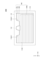
- FIG. 1 is a plan view showing an example of a configuration of a vehicle window glass according to an embodiment, as viewed from inside the vehicle.
- 2 is an enlarged view showing an example of a configuration of a portion surrounding a wiring prohibited area in the overall configuration of a vehicle window glass according to an embodiment.
- FIG. FIG. 4 is a diagram showing an example of a simulation result of temperature distribution in a vehicle window glass according to an embodiment.
- FIG. 4 is a diagram showing an example of a simulation result of temperature distribution in a vehicle window glass according to an embodiment.
- FIG. 11 is a diagram showing an example of a simulation result of temperature distribution in a comparative vehicle window glass.
- FIG. 11 is a diagram showing an example of a simulation result of temperature distribution in a comparative vehicle window glass.
- FIG. 11 is a diagram showing an example of the configuration of the first heating wire, the second heating wire, and the third heating wire in a second anti-fogging area of a vehicle window glass according to a first modified example of an embodiment.
- FIG. FIG. 11 is a diagram showing an example of a configuration of a vehicle window glass according to a second modified example of the embodiment.
- each plan view is a view of the glass surface of a glass plate for a vehicle window (hereinafter also referred to as "window glass”) viewed from the opposite side, and shows the window glass attached to the vehicle from a viewpoint from inside the vehicle (viewed from inside the vehicle).
- window glass a glass plate for a vehicle window
- the window glass is a windshield attached to the front of the vehicle or a rear glass attached to the rear of the vehicle
- the up/down direction of each plan view corresponds to the up/down direction of the vehicle
- the left/right direction of each plan view corresponds to the vehicle width direction of the vehicle.
- the window glass is not limited to a windshield or a rear glass, and may be, for example, a side glass attached to the side of the vehicle.
- the direction parallel to the X-axis (X-axis direction), the direction parallel to the Y-axis (Y-axis direction), and the direction parallel to the Z-axis (Z-axis direction) respectively represent the left-right direction of the glass plate, the up-down direction of the glass plate, and the direction perpendicular to the surface of the glass plate (also referred to as the normal direction).
- the X-axis direction, the Y-axis direction, and the Z-axis direction are mutually orthogonal.
- FIG. 1 is a plan view showing an example of the configuration of a vehicle window glass 100 as viewed from inside the vehicle.
- the vehicle window glass 100 has a configuration that is line-symmetrical with respect to a straight line that passes through the center in the left-right direction in the up-down direction in a plan view.
- the vehicle window glass 100 shown in FIG. 1 is an example of a rear window that is attached to the rear of a vehicle.
- the vehicle window glass 100 includes a glass plate 110 for a vehicle window and a defogger 120 provided on the glass plate 110.
- the defogger 120 has bus bars 130L, 130R, and a plurality of heating wires 140.
- the busbars 130L, 130R and the multiple heating wires 140 are formed, for example, by printing and baking a paste containing a conductive metal (e.g., silver paste, etc.) on the interior surface of the glass plate 110.
- the printing method of the paste containing a conductive metal can be screen printing, offset printing, gravure printing, flexographic printing, inkjet printing, etc.
- the thickness of the busbars 130L, 130R and the multiple heating wires 140 formed in this manner is approximately the same. Note that, since the thickness of the multiple heating wires 140 is approximately the same, the wider (thicker) the width (line width) of each heating wire 140 means that each heating wire 140 is thicker.
- the thickness of the busbars 130L, 130R and the multiple heating wires 140 may be 5 ⁇ m or more and 20 ⁇ m or less.
- the width of the multiple heating wires 140 may be 0.15 mm or more and 1.0 mm or less, or 0.15 mm or more and 0.5 mm or less.
- the method of forming the bus bars 130L, 130R and the multiple heating wires 140 is not limited to the above-mentioned method.
- the bus bars 130L, 130R and the multiple heating wires 140 may be formed by providing a linear or foil body containing a conductive material such as copper on the interior or exterior surface of the glass plate 110.
- the bus bars 130L, 130R and the multiple heating wires 140 may be attached to the glass plate 110 with an adhesive or the like, or may be provided inside (inner layer) of the glass plate 110 itself.
- a camera 20 can be mounted on the interior side of the vehicle window glass 100 to capture images of the exterior of the vehicle.
- FIG. 1 is a plan view showing the vehicle window glass 100 from the perspective of the interior of the vehicle, with the position of the camera 20 indicated by a dashed line. More specifically, the position of the camera 20 is the position of the lens of the camera 20.
- the imaging range of the camera 20 is set to the wiring prohibited area 113 in a plan view.
- the camera 20 is mounted on the inside of the vehicle relative to the glass plate 110, and is a device (imaging unit) that captures images of the outside of the vehicle (the rear of the vehicle in this embodiment) through the glass plate 110.
- images captured by the camera 20 can be displayed on a display inside the vehicle cabin, thereby helping the driver of the vehicle to visually recognize the situation around the vehicle.
- a lamp may be provided in the wiring prohibited area 113 instead of the camera 20.
- the lamp may be, for example, a high-mounted stop lamp.
- the lamp can emit light to notify the driver of the following vehicle that the brakes of the vehicle have been applied.
- the lamp is mounted on the inside of the vehicle relative to the glass plate 110, and is a device that emits light through the glass plate 110 toward the outside of the vehicle (to the rear of the vehicle in this embodiment).
- the glass plate 110 is an example of a glass plate for a vehicle window.
- the outer shape of the glass plate 110 is substantially rectangular.
- the upper edge 110U represents the glass edge on the upper side of the glass plate 110
- the lower edge 110B represents the glass edge on the lower side (opposite side to the upper edge 110U side) of the glass plate 110.
- the left edge 110L represents the glass edge on the left side of the glass plate 110
- the right edge 110R represents the glass edge on the right side (opposite side to the left edge 110L side) of the glass plate 110.
- the left edge 110L is the glass edge adjacent to the left side of the upper edge 110U and the lower edge 110B
- the right edge 110R is the glass edge adjacent to the right side of the upper edge 110U and the lower edge 110B.
- the glass plate 110 has a pair of side edges.
- the left edge 110L is an example of a first side edge of the pair of side edges
- the right edge 110R is an example of a second side edge of the other of the pair of side edges.
- the connection between the upper edge 110U and the left edge 110L is connected with a curvature, but may be connected without a curvature.
- the shapes of the connections between the other edges are similar.
- the glass plate 110 has a first anti-fogging area 111, a second anti-fogging area 112, a wiring prohibited area 113, and a concealing film 115.
- FIG. 2 is an enlarged view showing an example of the configuration of the portion surrounding the wiring prohibited area 113 within the overall configuration of the vehicle window glass 100.
- the camera 20 is omitted in FIG. 2.
- the first antifogging area 111 is an antifogging area of the glass plate 110 excluding a second antifogging area 112 located in the upper center and a wiring prohibited area 113 surrounded by the second antifogging area 112.
- the anti-fogging region of the glass plate 110 is a region that extends inward from the substantially rectangular region in which the plurality of heat wires 140 are provided, and is heated by the heat of the plurality of heat wires 140. This is the anti-fog area where fog is removed.
- the first anti-fogging region 111 is a generally U-shaped region consisting of the portion of the anti-fogging region of the glass plate 110 from the lower edge 110B side to the lower end of the second anti-fogging region 112, and the left and right portions of the second anti-fogging region 112.
- the portion of the anti-fogging region from the lower edge 110B side to the lower end of the second anti-fogging region 112 is, as an example, the portion where the fourth to fourteenth heat rays 140A from the top of the 14 heat rays 140 extend in the left-right direction.
- the outer edge of the first anti-fogging region 111 is located outside the portion of the opening 115A of the concealing film 115 other than the convex portion 115A1.
- the second antifogging region 112 is a region obtained by excluding the wiring prohibited region 113 from the central portion in the left-right direction of the upper end portion of the antifogging region of the glass plate 110.
- the portion in the vertical direction of the glass plate 110 where the first to third heating wires 141, 142, and 143 from the top of the 14 heating wires 140 are provided is shown. .
- the second anti-fogging region 112 surrounds the wiring prohibited region 113.
- the second anti-fogging region 112 is a substantially rectangular annular region surrounding the wiring prohibited region 113.
- FIG. 2 shows the inner edge 112A of the second anti-fogging region 112.
- the inner edge 112A is the inner edge of the substantially rectangular annular second anti-fogging region 112.
- the region inside the inner edge 112A is not included in the second anti-fogging region 112.
- the wiring prohibited region 113 is located inside the inner edge 112A of the second anti-fogging region 112.
- the second anti-fogging region 112 overlaps with substantially the entire convex portion 115A1 of the concealing film 115.
- the lower end of the second anti-fogging region is located between the third heat ray 143 and the fourth heat ray 140A.
- the lower end of the convex portion 115A1 of the concealing film 115 protrudes downward from the second antifogging region 112, but the lower end of the convex portion 115A1 may be contained within the second antifogging region 112.
- the wiring prohibited area 113 is an area surrounded by the second antifogging area 112 in the central portion in the left-right direction on the upper edge 110U side of the glass plate 110.
- the wiring prohibited area 113 is an area in which wiring such as a heating wire and an antenna cannot be provided.
- the wiring prohibited area 113 is, for example, a trapezoidal area in plan view, the lower base of which is longer than the upper base.
- the outer edge of the wiring prohibited area 113 is trapezoidal.
- the wiring prohibited area 113 is a part of the vehicle.
- the image capturing area includes an image capturing area defined by the angle of view of the camera 20 installed in the room facing rearward, and is wider than the image capturing area defined by the angle of view. This can be displayed on a vehicle display or the like.
- the composite heat ray 141M of the first heat ray 141 and the second heat ray 142, and the third heat ray 143 surround the wiring prohibited area 113 and are located outside the wiring prohibited area 113, so that the composite heat ray 141M and the third heat ray 143 can be prevented from being reflected in the image captured by the camera 20.
- the composite heat ray 141M and the third heat ray 143 are energized and generate heat, so that heat is transferred from the second anti-fogging area 112 outside the wiring prohibited area 113 to the wiring prohibited area 113, and the fogging within the wiring prohibited area 113 can be removed.
- the wiring prohibited area 113 is located in the center in the left-right direction on the upper edge 110U side of the glass plate 110, but the wiring prohibited area 113 may be located in a part other than the center in the left-right direction on the upper edge 110U side of the glass plate 110. As an example, the wiring prohibited area 113 may be located to the right or left of the center in the left-right direction on the upper edge 110U side of the glass plate 110.
- the concealing film 115 is a frame-shaped film provided along the outer edge (upper edge 110U, left edge 110L, lower edge 110B, and right edge 110R) of the glass plate 110.
- the concealing film 115 has an opening 115A that exposes almost the entire inside of the outer edge of the glass plate 110, and an opening 115B that exposes the wiring prohibited area 113.
- the opening 115A has a convex portion 115A1 that protrudes downward from the upper edge 110U side and a convex portion 115A2 that protrudes upward from the lower edge 110B side so as to surround the wiring prohibited area 113 in the upper central part of the glass plate 110.
- the convex portion 115A1 protrudes downward to surround the wiring prohibited area 113, and the convex portion 115A2 protrudes upward to avoid the drive shaft of a wiper (not shown).
- the opening 115B is provided in the protruding portion 115A1 and is a trapezoidal opening in a plan view that exposes the entire wiring prohibited area 113.
- the opening area of the opening 115B is equal to the wiring prohibited area 113.
- the concealing film 115 avoids the wiring prohibited area 113, so that the concealing film 115 can be prevented from being reflected in the image captured by the camera 20.
- a specific example of the concealing film 115 is ceramics such as a black ceramic film.
- the concealing film 115 is formed by printing and baking a ceramic paste containing a black pigment and glass frit on the interior surface of the glass plate 110.
- the printing method for the ceramic paste containing a black pigment and glass frit can be screen printing, offset printing, gravure printing, flexographic printing, inkjet printing, or the like.
- the defogger 120 is an electrically heated conductor pattern that removes fogging from the glass plate 110.
- the defogger 120 has a plurality of heating wires 140 extending in the left-right direction of the glass plate 110, and a plurality of bus bars 130L, 130R that feed electricity to the plurality of heating wires 140.
- the glass plate 110 is provided with 14 heating wires 140 that extend in the left-right direction of the glass plate 110 so as to run parallel to each other, and a pair of bus bars 130L, 130R connected to the 14 heating wires 140. When a voltage is applied between the pair of bus bars 130L, 130R, the 14 heating wires 140 are electrically energized and generate heat, thereby removing fogging from the glass plate 110.
- the bus bars 130L, 130R are conductor patterns extending in the up-down direction along the left edge 110L and the right edge 110R of the glass plate 110.
- the left bus bar 130L is an example of a first bus bar
- the right bus bar 130R is an example of a second bus bar.
- Fourteen heating wires 140 are connected between the bus bars 130L, 130R.
- the bus bars 130L, 130R are located outside the opening 115A of the concealing film 115 and overlap with the concealing film 115.
- bus bar 130L is connected to one terminal (for example, a positive terminal) of a DC power supply (not shown) of the vehicle, and bus bar 130R is connected to the other terminal (for example, a negative terminal) of the DC power supply (not shown) of the vehicle.
- DC power is supplied to bus bars 130L and 130R from a DC power supply (not shown) of the vehicle.
- bus bars 130L, 130R shown in FIG. 1 are clearly wider than the heating wire 140, the bus bars 130L, 130R may be of approximately the same width as the heating wire 140. However, since the bus bars 130L, 130R are located at the left and right ends of the first anti-fogging region 111, they are parts that do not contribute to heating the first anti-fogging region 111, regardless of their width. Also, although the bus bars 130L, 130R are located inside the first anti-fogging region 111 in FIG. 1, the bus bars 130L, 130R may be located outside the first anti-fogging region 111.
- the fourteen heating wires 140 are conductor patterns connected between the bus bars 130L and 130R.
- the width of the heating wires 140 means the line width.
- Each of the 14 heat wires 140 has a left end connected to the left bus bar 130L and a right end connected to the right bus bar 130R.
- the left end of each heat wire 140 is the connection between the left bus bar 130L and each heat wire 140
- the right end of each heat wire 140 is the connection between the right bus bar 130R and each heat wire 140.
- the left and right ends of the 14 heat wires 140 overlap the concealing film 115.
- the top three heat rays 140 of the 14 heat rays 140 are the first heat ray 141, the second heat ray 142, and the third heat ray 143.
- the first heat ray 141 is the first heat ray located at the top
- the second heat ray 142 is the second heat ray from the top
- the third heat ray 143 is the third heat ray from the top.
- the top three heat rays 140 of the 14 heat rays 140 are to be particularly distinguished, they are referred to as the first heat ray 141, the second heat ray 142, and the third heat ray 143.
- heat ray 140A When the fourth to fourteenth heat rays 140 from the top other than the top three heat rays 140 (the first heat ray 141, the second heat ray 142, and the third heat ray 143) of the 14 heat rays 140 are to be distinguished, they are referred to as heat ray 140A. Furthermore, when there is no need to distinguish between the 14 heat rays 140, they will simply be referred to as heat rays 140.
- the 14 heating wires 140 have a left-right symmetrical shape with a straight line passing through the left-right center of the glass plate 110 in the up-down direction as the axis of symmetry.
- the 14 heating wires 140 do not have to have a left-right symmetrical shape with respect to the above-mentioned axis of symmetry.
- the wiring prohibited area 113 is located in a part other than the left-right center part on the upper edge 110U side of the glass plate 110, the shape of the 14 heating wires 140 will be left-right asymmetric.
- the fourth to fourteenth heating wires 140A are connected between the bus bars 130L and 130R and extend in the left-right direction in a region of the first antifogging region 111 that is below the second antifogging region 112. Except for the left and right ends, the fourth to fourteenth heating wires 140A do not overlap the concealing film 115 and are located inside the opening 115A.
- the vertical spacing between the fourth to fourteenth heating wires 140A is approximately constant. It is also preferable that the fourth to fourteenth heating wires 140A have approximately the same length between the bus bars 130L and 130R and the same resistance value. This makes it possible to make the speed at which frost is removed uniform, preventing uneven frost removal.
- the 13th heating wire 140A and the 14th heating wire 140A are connected to each other in the left-right center to form a single composite heating wire 140A1 in order to avoid the convex portion 115A2. If the 14th heating wire 140A were to bend upward to avoid the convex portion 115A2, the distance between the 13th heating wire 140A would narrow and the temperature distribution would become uneven, so by providing the composite heating wire 140A1, an even temperature distribution is obtained.
- the first heat wire 141, the second heat wire 142, and the third heat wire 143 are connected between the bus bars 130L and 130R on the left and right sides of the convex portion 115A1 of the concealing film 115, similar to the fourth to fourteenth heat wires 140A, and extend in the left-right direction.
- the first heat wire 141, the second heat wire 142, and the third heat wire 143 are wired at intervals approximately equal to the vertical intervals of the fourth to fourteenth heat wires 140A on the left and right sides of the convex portion 115A1 above the concealing film 115.
- first to third heat wires from the top of the 14 heat wires 140A are the first heat wire 141, the second heat wire 142, and the third heat wire 143 will be described, but one or more heat wires 140 may be provided on the first heat wire 141.
- First hot wire 141 and second hot wire 142 are connected to each other at connection portions 141S provided on the left and right sides of the wiring prohibited area 113 (opening 115B) inside the protrusion 115A1 to form a single composite wire. That is, the first heating wire 141 and the second heating wire 142 are integrated between the two connecting portions 141S to form a single composite heating wire 141M.
- the first heating wire 141 has a heating wire portion 141A that bends toward the second heating wire 142 and extends diagonally downward at the center of the glass plate 110 in the left-right direction.
- the lower end of the heating wire portion 141A is connected to the second heating wire 142 at a connection portion 141S.
- the heating wire portion 141A and the connection portion 141S are located within the second anti-fogging area 112 and overlap with the concealing film 115.
- a portion of the portion of the first heating wire 141 that extends in the left-right direction, which is closer to the heating wire portion 141A, and a portion of the portion of the second heating wire 142 that is closer to the connection portion 141S, are located within the second anti-fogging area 112 and overlap with the concealing film 115.
- first heat wire 141 and the second heat wire 142 are connected at the connection part 141S to form a single composite heat wire 141M.
- another heat wire may be connected at the connection part 141S to form a single composite heat wire 141M.
- three or more heat wires 140 may be connected at the connection part 141S to form a single composite heat wire 141M.
- connection parts 141S of the first heating wire 141 and the second heating wire 142 are provided on the left and right sides of the wiring prohibited area 113, but the connection parts 141S may be provided on either the left or right side of the wiring prohibited area 113. In this case, on the left or right side of the wiring prohibited area 113 where the connection parts 141S are not present, as an example, only one of the first heating wire 141 and the second heating wire 142 is present.
- connection parts 141S may be provided on either the left or right side of the wiring prohibited area 113.
- the composite heat ray 141M is a part of the first heat ray 141 and the second heat ray 142. As shown in FIG. 2, the composite heat ray 141M has composite heat ray portions 141M1, 141M2, 141M3, 141M4, 141M5, 141M6, and 141M7.
- the composite heat wire 141M has a configuration in which composite heat wire portions 141M1 to 141M7 are connected between two connecting portions 141S on the left and right. The composite heat wire 141M overlaps with the shielding film 115.
- Composite heating wire portion 141M1 extends diagonally downward to the right from the connection portion 141S on the left side and is connected to composite heating wire portion 141M2.
- Composite heating wire portion 141M2 extends rightward from its connection portion with composite heating wire portion 141M1 to just before the wiring prohibited area 113 and is connected to composite heating wire portion 141M3.
- Composite heating wire portion 141M3 extends diagonally upward to the right from its connection portion with composite heating wire portion 141M2 along the left edge of the wiring prohibited area 113 and is connected to composite heating wire portion 141M4.
- Composite heating wire portion 141M4 extends rightward from its connection portion with composite heating wire portion 141M3 along the upper edge of the wiring prohibited area 113 and is connected to composite heating wire portion 141M5.
- Composite heating wire portion 141M5 extends diagonally downward to the right from its connection with composite heating wire portion 141M4 along the right edge of wiring prohibited area 113 and is connected to composite heating wire portion 141M6.
- Composite heating wire portion 141M6 extends right from its connection with composite heating wire portion 141M5 and is connected to composite heating wire portion 141M7.
- Composite heating wire portion 141M7 extends diagonally upward to the right from its connection with composite heating wire portion 141M6 to connection portion 141S on the right side.
- the composite heating wire portion 141M1 extends diagonally downward to the right from the left connection portion 141S in order to increase the area of the trapezoidal outer edge of the wiring prohibited area 113 that is surrounded by the composite heating wire 141M and the third heating wire 143. This is to make the temperature distribution of the glass plate 110 in the wiring prohibited area 113 uniform. Also, when viewed from the busbar 130L side, the composite heating wire portion 141M1 is a heating wire in which the first heating wire 141 and the second heating wire 142 join at the left connection portion 141S to form a single wire, so that a current flows that is the sum of the currents flowing through the first heating wire 141 and the second heating wire 142.
- the width of the composite heating wire portion 141M1 is made wider than the width of the first heating wire 141 and the second heating wire 142.
- the width of the composite heat ray portion 141M1 is made wider than the width of the first heat ray 141 and the second heat ray 142.
- the configuration of the composite heat ray portion 141M1 has a configuration that is the left-right inverted configuration of the composite heat ray portion 141M7.
- the vertical distance between the composite heat ray part 141M2 and the third heat ray 143 directly below is narrower than the vertical distance between the fourth to fourteenth heat ray 140A and the vertical distance between the first heat ray 141 to the third heat ray 143, so the width of the composite heat ray part 141M2 is made wider than the width of the heat ray 140A and the first heat ray 141 to the third heat ray 143.
- the heat generation amount of the composite heat ray part 141M2 is reduced below the heat generation amount of the third heat ray 143, and the temperature distribution of the part where the composite heat ray part 141M2 and the third heat ray 143 are present is aligned with the surrounding temperature distribution.
- the configuration of the composite heat ray part 141M2 has a configuration that is the left-right inversion of the composite heat ray part 141M6.
- the composite heating ray sections 141M3-141M5 extend above the wiring prohibited area 113 along the upper, left, and right sections of the trapezoidal wiring prohibited area 113 in a plan view (the sections of the three sides other than the bottom base of the trapezoid).
- the composite heating ray section 141M4 is a section of the composite heating ray 141M that extends left and right above the wiring prohibited area 113.
- the width of the composite heating ray sections 141M3-141M5 is narrower than the width of the composite heating ray section 141M2, and is configured to generate more heat than the composite heating ray section 141M2.
- the width of the composite heating wire portions 141M3-141M5 is constant from the connection of the composite heating wire portion 141M3 with the composite heating wire portion 141M2 to the connection of the composite heating wire portion 141M5 with the composite heating wire portion 141M6. This is to heat approximately the upper half of the wiring prohibited area 113 evenly with a uniform amount of heat generation. Note that the current flowing through the composite heating wire portion 141M2 flows directly through the composite heating wire portions 141M3-141M5, so the width of the composite heating wire portions 141M3-141M5 is wider than the width of the first heating wire 141 and the second heating wire 142.
- the composite heating ray section 141M6 has a configuration that is the left-right inversion of the composite heating ray section 141M2.
- the vertical distance between the composite heating ray section 141M6 and the third heating ray 143 located directly below is narrower than the vertical distance between the fourth to fourteenth heating ray 140A and the vertical distance between the first heating ray 141 to the third heating ray 143, so the width of the composite heating ray section 141M6 is made wider than the width of the heating ray 140A and the first heating ray 141 to the third heating ray 143.
- the composite heating ray section 141M7 has a configuration that is the left-right inversion of the composite heating ray section 141M1.
- the composite heating ray section 141M7 is positioned in the same position as the composite heating ray section 141M1 in the vertical direction to increase the area of the trapezoidal outer edge of the wiring prohibited area 113 that is surrounded by the composite heating ray 141M and the third heating ray 143, and to make the temperature distribution of the wiring prohibited area 113 symmetrical.
- the left-right length of the composite heating ray section 141M7 is equal to the left-right length of the composite heating ray section 141M1.
- the composite heat ray portions 141M3 and 141M5 overlap with the concealing film 115.
- the 14 heat rays 140 extend in the left-right direction, which corresponds to the horizontal direction, in most areas, so heat rays that are angled relative to the left-right direction are easy to notice. Heat rays that extend in the left-right direction, which corresponds to the horizontal direction, are difficult for humans to see because they overlap with the horizontal parts of the scenery seen through the glass plate 110, but heat rays that are angled relative to the left-right direction tend to be easy to see and stand out.
- the composite heating ray portions 141M3 and 141M5 are angled in the left-right direction, but are located outside the opening 115B surrounding the wiring prohibited area 113 and overlap with the concealing film 115, so they are not noticeable. This allows for good design without compromising the appearance of the glass plate 110. Note that the composite heating ray portions 141M3 and 141M5 do not have to overlap with the concealing film 115. In this case, the heating ray portion 141A of the first heating ray 141 does not have to overlap with the concealing film 115 either.
- the third heating wire 143 extends in the left-right direction below the wiring prohibited area 113.
- the third heating wire 143 is bent downward in a crank shape directly below the wiring prohibited area 113 in order to avoid the wiring prohibited area 113, compared to the sections to the left and right of the wiring prohibited area 113.
- the third heating wire 143 may not be bent between the bus bars 130L and 130R, but may extend linearly like the fourth to fourteenth heating wires 140.
- the first heat ray 141 and the second heat ray 142 are integrated between two connection parts 141S on both sides of the wiring prohibited area 113 to form a single composite heat ray 141M, which extends along the left, upper, and right sections of the outer edge of the wiring prohibited area 113, and the third heat ray 143 extends along the lower section of the outer edge of the wiring prohibited area 113.
- the vertical distance between the composite heat ray parts 141M2 and 141M6 of the composite heat ray 141M and the third heat ray 143 is narrowed, and the composite heat ray parts 141M2 and 141M6 are close to the third heat ray 143.
- the temperature of the wiring prohibited area 113 of the glass plate 110 can be raised to a desired temperature and the temperature distribution can be made more uniform. This allows the haze in the wiring prohibited area 113 to be removed evenly.
- the temperature distribution between the third heating ray 143 and the composite heating ray portions 141M2 and 141M6 is made more uniform than other portions.
- the temperature of the wiring prohibited area 113 of the glass plate 110 can be raised to a desired temperature, and the temperature distribution can be made more uniform, ensuring that fogging in the wiring prohibited area 113 is evenly and reliably removed.
- FIGS. 3A and 3B are diagrams showing an example of a simulation result of temperature distribution in the vehicle window glass 100 of the embodiment.
- Fig. 3A shows the temperature distribution in the portion from the first heat ray 141 to the fourth heat ray 140A of the glass sheet 110
- Fig. 3B shows an enlarged view of the temperature distribution in and around the wiring prohibited area 113.
- the wiring prohibited area 113 is shown as a trapezoid with a dashed line.
- Figure 3A the temperature distribution 30 minutes after a current of a specified power is passed between busbars 130L and 130R is shown in Figures 3A and 3B.
- Figure 3B also shows the state in which the widths of composite heating wire portions 141M1 to 141M7 of composite heating wire 141M are set as described above.
- an overall temperature distribution of approximately 25°C or higher was obtained in the portion of the glass plate 110 from the first heating wire 141 to the fourth heating wire 140A.
- the maximum temperature was 56.271°C at the center in the left-right direction of the third heating wire 143.
- the temperature was 27.0°C at the center of the wiring prohibited area 113, 30°C to 45°C at the center of the upper part of the wiring prohibited area 113, and 35°C at the lower corner of the wiring prohibited area 113, and a good temperature distribution was obtained within the wiring prohibited area 113.
- a good temperature distribution means that there is little temperature difference and the temperature is distributed evenly.
- the width of the composite heating wire portions 141M3-141M5 is narrower than that of the composite heating wire portion 141M2, and is configured to generate more heat than the composite heating wire portion 141M2. Furthermore, the width of the composite heating wire portions 141M3-141M5 is constant from the connection of the composite heating wire portion 141M3 with the composite heating wire portion 141M2 to the connection of the composite heating wire portion 141M5 with the composite heating wire portion 141M6, so that a good temperature distribution is obtained within the wiring prohibited area 113, as shown in Figure 3B.
- 3C and 3D are diagrams showing an example of a simulation result of the temperature distribution in a comparative vehicle window glass.
- the comparative vehicle window glass is a vehicle window glass of International Publication No. 2019/017246 described as Patent Document 1.
- FIG. 3C shows the temperature distribution in a portion where three heat wires are provided from the upper side of the glass plate of the comparative vehicle window glass, and
- FIG. 3C shows an enlarged view of the temperature distribution in the wiring prohibited area and its surroundings.
- FIG. 3D shows the wiring prohibited area of the comparative vehicle window glass as a dashed trapezoid.
- Figures 3C and 3D show the temperature distribution 30 minutes after a current of the same power as that passed in the simulation of the vehicle window glass 100 of the embodiment is passed between the left and right bus bars.
- the first to third heating wires from the top had an overall temperature distribution of about 25°C or higher, but it was found that the temperature above the wiring prohibited area was lower than that of the vehicle window glass 100 of the embodiment.
- the maximum temperature was 57.679°C in the area where the first heating wire is bent on the left and right sides of the wiring prohibited area as shown in Figure 3C.
- the temperature was 26.1°C in the center of the wiring prohibited area, 26°C to 29°C in the center of the upper part of the wiring prohibited area, and 30°C at the lower corner of the wiring prohibited area.
- the temperature was lower overall and the temperature difference was larger.
- the vehicle window glass 100 of the embodiment is able to achieve an overall increase in temperature and improved uniformity of temperature distribution within the wiring prohibited area 113 compared to the comparative vehicle window glass by providing a composite heating wire 141M, which combines the first heating wire 141 and the second heating wire 142 into a single wire, along the left, upper, and right sides of the wiring prohibited area 113, and providing a third heating wire 143 along the lower side of the wiring prohibited area 113.
- FIG. 4A is a diagram showing an example of the configuration of a first heating wire 141, a second heating wire 142, and a third heating wire 143 in a second antifogging area 112 of a vehicle window glass 100A according to a first modified example of the embodiment.
- the first heating wire 141 extends to the left and right above the wiring prohibited area 113, and the second heating wire 142 and the third heating wire 143 are connected at two connection parts 142S located on the left and right of the wiring prohibited area 113 to form a single composite heating wire 142M.
- the first heating wire 141 is not connected to the other heating wires.
- the third heating wire 143 has a heating wire portion 143A that bends toward the second heating wire 142 and extends diagonally upward at the center of the glass plate 110 in the left-right direction.
- the upper end of the heating wire portion 143A is connected to the second heating wire 142 at a connection portion 142S.
- the heating wire portion 143A and the connection portion 142S are located within the second anti-fogging area 112 and overlap with the concealing film 115, which is not shown in FIG. 4A.
- the portions of the second heating wire 142 and the third heating wire 143 shown in FIG. 4A that extend in the left-right direction are located within the second anti-fogging area 112 and overlap with the concealing film 115, which is not shown in FIG. 4A.
- the composite heat ray 142M is a part of the second heat ray 142 and the third heat ray 143. As shown in FIG. 4A, the composite heat ray 142M has composite heat ray portions 142M1, 142M2, 142M3, 142M4, 142M5, 142M6, and 142M7.
- the composite heat wire 142M has a configuration in which composite heat wire portions 142M1 to 142M7 are connected between two connecting portions 142S on the left and right sides. The composite heat wire 142M overlaps with the shielding film 115, which is not shown in FIG. 4A.
- Composite heating wire part 142M1 extends diagonally upward to the right from the connection part 142S on the left side and is connected to composite heating wire part 142M2.
- Composite heating wire part 142M2 extends rightward from its connection part with composite heating wire part 142M1 to just before the wiring prohibited area 113 and is connected to composite heating wire part 142M3.
- Composite heating wire part 142M3 extends diagonally downward to the left from its connection part with composite heating wire part 142M2 along the left edge of the wiring prohibited area 113 and is connected to composite heating wire part 142M4.
- Composite heating wire part 142M4 extends rightward from its connection part with composite heating wire part 142M3 along the lower edge of the wiring prohibited area 113 and is connected to composite heating wire part 142M5.
- the composite heating wire portion 142M5 extends diagonally upward and to the left from its connection with the composite heating wire portion 142M4 along the right edge of the wiring prohibited area 113 and is connected to the composite heating wire portion 142M6.
- the composite heating wire portion 142M6 extends to the right from its connection with the composite heating wire portion 142M5 and is connected to the composite heating wire portion 142M7.
- the composite heating wire portion 142M7 extends diagonally downward and to the right from its connection with the composite heating wire portion 142M6 to the connection portion 142S on the right side.
- the configuration of the composite heating wire section 142M1 has a configuration that is the left-right inversion of the composite heating wire section 142M7.
- the widths of the composite heating wire sections 142M1 to 142M7 may be set to the same widths as the composite heating wire sections 141M1 to 141M7 shown in FIG. 2.
- the widths of the composite heating wire sections 142M3 to 142M5 may be set constant between the composite heating wire sections 142M2 and 142M6 in order to make the temperature distribution in the wiring prohibited area 113 uniform.
- the first modified vehicle window glass 100A may include a composite heat ray 142M in which the second heat ray 142 and the third heat ray 143 are combined into one.
- Fig. 4B is a diagram showing an example of the configuration of a vehicle window glass 100B of a second modified example of the embodiment.
- Fig. 4B shows a simplified overall view, and further shows a simplified view of a plurality of heat rays 140.
- the vehicle window glass 100B of the second modified example has a different configuration of the concealing film 115 from the configuration of the concealing film 115 of the vehicle window glass 100 shown in Figs. 1 and 2.
- components other than the glass plate 110, the wiring prohibited area 113, the concealing film 115, and the simplified plurality of heat rays 140 are omitted.
- the concealing film 115 has an opening 115A with two protrusions 115A11 and 115A12.
- the two protrusions 115A11 and 115A12 have a configuration in which the portion of the protrusion 115A1 shown in FIG. 2 that is located below the wiring prohibited area 113 is omitted. Therefore, the lower section of the outer edge of the wiring prohibited area 113 is not surrounded by the concealing film 115.
- the third heat ray 143 extends left and right below the two protrusions 115A11 and 115A12, and does not have a section that overlaps with the concealing film 115.
- the second modified vehicle window glass 100B may be configured such that the lower section of the outer edge of the wiring prohibited area 113 is not surrounded by the concealing film 115, and the third heat ray 143 does not have a section overlapping with the concealing film 115.
- the vehicle window glass 100 includes a glass sheet 110 for a vehicle window, the glass sheet 110 having a wiring prohibited area 113, and a defogger 120 provided on the glass sheet 110.
- the defogger 120 has a pair of bus bars 130L, 130R extending in the up-down direction of the glass sheet 110, and a plurality of heat wires 140 connected between the pair of bus bars 130L, 130R and extending in the left-right direction of the glass sheet 110.
- the glass sheet 110 has a first anti-fogging area 111 extending in the left-right direction between the pair of bus bars 130L, 130R, and a second anti-fogging area 112 formed to surround the wiring prohibited area 113.
- the plurality of heat wires 140 include a first heat wire 141, a second heat wire 142, and a and a third heat ray 143, the first heat ray 141 and the second heat ray 142 are connected to each other at a connection portion 141S located around the wiring prohibited area 113 to form a single composite heat ray 141M, and the composite heat ray 141M has a section extending in the left-right direction above the wiring prohibited area 113, and the third heat ray 143 has a section extending in the left-right direction below the wiring prohibited area 113, or the first heat ray 141 has a section extending in the left-right direction above the wiring prohibited area 113, and the second heat ray 142 and the third heat ray 143 are connected to each other at a connection portion 142S located around the wiring prohibited area 113 to form a single composite heat ray 142M, and the composite heat ray 142M has a section extending in the left-right direction below the wiring prohibited area 113.
- the wiring prohibited area 113 can be heated from above by the combined heat ray 141M and from below by the third heat ray 143.
- the wiring prohibited area 113 can be heated from above by the first heat ray 141 and from below by the combined heat ray 142M.
- the glass plate 110 also has a concealing film 115 formed along the outer edge of the glass plate 110 in a plan view, and the concealing film 115 surrounds the outer edge of the wiring prohibited area 113.
- the section extending in the left-right direction below the wiring prohibited area 113 of the third heat ray 143, or the section extending in the left-right direction below the wiring prohibited area 113 of the composite heat ray 142M, may overlap with the concealing film 115. Therefore, the section extending in the left-right direction below the wiring prohibited area 113 of the third heat ray 143, or the section extending in the left-right direction below the wiring prohibited area 113 of the composite heat ray 142M, cannot be seen from the outside of the vehicle. Therefore, a vehicle window glass 100 with excellent design and good temperature distribution in the wiring prohibited area 113 can be provided.
- the glass plate 110 has a concealing film 115 formed along the outer edge of the glass plate 110 in a plan view, and the concealing film 115 surrounds the upper section, the left section, and the right section of the upper, lower, left and right sections of the outer edge of the wiring prohibited area 113, and is not provided in the lower section of the outer edge of the wiring prohibited area 113, and the section extending in the left-right direction below the wiring prohibited area 113 of the third heat ray 143 or the section extending in the left-right direction below the wiring prohibited area 113 of the composite heat ray 142M may be exposed from the concealing film 115.
- the section extending in the left-right direction below the wiring prohibited area 113 of the third heat ray 143 or the section extending in the left-right direction below the wiring prohibited area 113 of the composite heat ray 142M is visible from the outside of the vehicle, but the portion of the glass plate 110 covered by the concealing film 115 can be reduced. Therefore, it is possible to provide a vehicle window glass 100 that has a good temperature distribution in the wiring prohibited area 113 while reducing the portion of the glass plate 110 that is covered by the concealing film 115.
- the composite heat ray 141M of the first heat ray 141 and the second heat ray 142 may be thicker than the portion other than the composite heat ray 141M of the first heat ray 141 and the second heat ray 142, or the composite heat ray 142M of the second heat ray 142 and the third heat ray 143 may be thicker than the portion other than the composite heat ray 142M of the second heat ray 142 and the third heat ray 143.
- the width of the composite heat ray 141M thicker than the width of the portion other than the composite heat ray 141M of the first heat ray 141 and the second heat ray 142, the amount of heat generated in the composite heat ray 141M can be reduced and the temperature distribution can be made more uniform.
- the heat generation amount in the composite heat ray 142M can be made equal to the heat generation amount in the parts of the second heat ray 142 and the third heat ray 143 other than the composite heat ray 142M, and the temperature distribution in the wiring prohibited area 113 can be made more uniform.
- the composite heat ray 141M of the first heat ray 141 and the second heat ray 142 is provided along the upper section, the left section, and the right section of the upper, lower, left, and right sections of the outer edge of the wiring prohibited area 113, and the thickness of the portion where the composite heat ray 141M is provided along the upper section, the left section, and the right section may be thicker than the portion other than the composite heat ray 141M of the first heat ray 141 and the second heat ray 142.
- the heat generation amount in the composite heat ray 141M can be made equal to the heat generation amount of the portion other than the composite heat ray 141M of the first heat ray 141 and the second heat ray 142.
- first heat ray 141 and the second heat ray 142 extend in the left-right direction to the left of the wiring prohibited area 113 and extend in the left-right direction to the right of the wiring prohibited area 113
- connection portion 141S is the connection portion 141S located on the left side of the wiring prohibited area 113 and the connection portion 141S located on the right side of the wiring prohibited area 113
- the composite heat ray 141M of the first heat ray 141 and the second heat ray 142 connects between the connection portion 141S located on the left side of the wiring prohibited area 113 and the connection portion 141S located on the right side of the wiring prohibited area 113, and may have a section extending in the left-right direction above the wiring prohibited area 113.
- the wiring prohibited area 113 can be heated from above by the composite heat ray 141M and can be heated from below by the third heat ray 143. Therefore, in a configuration in which the composite heat ray 141M extends between the left and right first heat ray 141 and second heat ray 142, it is possible to provide a vehicle window glass 100 with good temperature distribution in the wiring prohibited area 113.
- the second heat ray 142 and the third heat ray 143 extend in the left-right direction to the left of the wiring prohibited area 113 and extend in the left-right direction to the right of the wiring prohibited area 113, and the connection portion 142S is the connection portion 142S located on the left side of the wiring prohibited area 113 and the connection portion 142S located on the right side of the wiring prohibited area 113, and the composite heat ray 142M of the second heat ray 142 and the third heat ray 143 connects between the connection portion 142S located on the left side of the wiring prohibited area 113 and the connection portion 142S located on the right side of the wiring prohibited area 113, and may have a section extending in the left-right direction below the wiring prohibited area 113.
- the wiring prohibited area 113 can be heated from above by the first heat ray 141 and from below by the composite heat ray 142M. Therefore, in a configuration in which the composite heat ray 142M extends between the left and right second heat ray 142 and the third heat ray 143, it is possible to provide a vehicle window glass 100 with good temperature distribution in the wiring prohibited area 113.
Landscapes
- Engineering & Computer Science (AREA)
- Mechanical Engineering (AREA)
- Surface Heating Bodies (AREA)
Priority Applications (4)
| Application Number | Priority Date | Filing Date | Title |
|---|---|---|---|
| CN202480008658.9A CN120584058A (zh) | 2023-01-26 | 2024-01-22 | 车辆用窗玻璃 |
| DE112024000632.9T DE112024000632T5 (de) | 2023-01-26 | 2024-01-22 | Fahrzeugfensterglas |
| JP2024573047A JPWO2024157940A1 (https=) | 2023-01-26 | 2024-01-22 | |
| US19/280,680 US20250346210A1 (en) | 2023-01-26 | 2025-07-25 | Vehicle window glass |
Applications Claiming Priority (2)
| Application Number | Priority Date | Filing Date | Title |
|---|---|---|---|
| JP2023-010467 | 2023-01-26 | ||
| JP2023010467 | 2023-01-26 |
Related Child Applications (1)
| Application Number | Title | Priority Date | Filing Date |
|---|---|---|---|
| US19/280,680 Continuation US20250346210A1 (en) | 2023-01-26 | 2025-07-25 | Vehicle window glass |
Publications (1)
| Publication Number | Publication Date |
|---|---|
| WO2024157940A1 true WO2024157940A1 (ja) | 2024-08-02 |
Family
ID=91970622
Family Applications (1)
| Application Number | Title | Priority Date | Filing Date |
|---|---|---|---|
| PCT/JP2024/001701 Ceased WO2024157940A1 (ja) | 2023-01-26 | 2024-01-22 | 車両用窓ガラス |
Country Status (5)
| Country | Link |
|---|---|
| US (1) | US20250346210A1 (https=) |
| JP (1) | JPWO2024157940A1 (https=) |
| CN (1) | CN120584058A (https=) |
| DE (1) | DE112024000632T5 (https=) |
| WO (1) | WO2024157940A1 (https=) |
Citations (4)
| Publication number | Priority date | Publication date | Assignee | Title |
|---|---|---|---|---|
| JP2005001948A (ja) * | 2003-06-12 | 2005-01-06 | Asahi Glass Co Ltd | 合わせガラスおよびその製造方法 |
| JP2018135020A (ja) * | 2017-02-22 | 2018-08-30 | 日本板硝子株式会社 | リアガラス |
| WO2019017246A1 (ja) * | 2017-07-18 | 2019-01-24 | Agc株式会社 | 車両用窓ガラス |
| JP2021086712A (ja) * | 2019-11-27 | 2021-06-03 | 株式会社デンソー | フィルムヒータ |
-
2024
- 2024-01-22 CN CN202480008658.9A patent/CN120584058A/zh active Pending
- 2024-01-22 WO PCT/JP2024/001701 patent/WO2024157940A1/ja not_active Ceased
- 2024-01-22 DE DE112024000632.9T patent/DE112024000632T5/de active Pending
- 2024-01-22 JP JP2024573047A patent/JPWO2024157940A1/ja active Pending
-
2025
- 2025-07-25 US US19/280,680 patent/US20250346210A1/en active Pending
Patent Citations (4)
| Publication number | Priority date | Publication date | Assignee | Title |
|---|---|---|---|---|
| JP2005001948A (ja) * | 2003-06-12 | 2005-01-06 | Asahi Glass Co Ltd | 合わせガラスおよびその製造方法 |
| JP2018135020A (ja) * | 2017-02-22 | 2018-08-30 | 日本板硝子株式会社 | リアガラス |
| WO2019017246A1 (ja) * | 2017-07-18 | 2019-01-24 | Agc株式会社 | 車両用窓ガラス |
| JP2021086712A (ja) * | 2019-11-27 | 2021-06-03 | 株式会社デンソー | フィルムヒータ |
Also Published As
| Publication number | Publication date |
|---|---|
| CN120584058A (zh) | 2025-09-02 |
| JPWO2024157940A1 (https=) | 2024-08-02 |
| US20250346210A1 (en) | 2025-11-13 |
| DE112024000632T5 (de) | 2025-11-20 |
Similar Documents
| Publication | Publication Date | Title |
|---|---|---|
| JP7259747B2 (ja) | 車両用窓ガラス | |
| JP2011501715A (ja) | 電気的に加熱可能なコーティングを備える透明な窓 | |
| JP6137191B2 (ja) | 車両用窓ガラスおよびその取付構造 | |
| KR20090039762A (ko) | 투명 전극 | |
| JP2020508949A (ja) | 合わせガラスとその製造方法 | |
| JP5488202B2 (ja) | 車載カメラ | |
| WO2024157940A1 (ja) | 車両用窓ガラス | |
| JP7205341B2 (ja) | 車両用ガラス | |
| JP2017505256A (ja) | 加熱されるフロントガラス | |
| WO2020196316A1 (ja) | ライダ装置 | |
| JP5447826B2 (ja) | 車両用後部窓ガラスアンテナ装置 | |
| CN114619852B (zh) | 防雾装置 | |
| WO2021200590A1 (ja) | 防曇発熱体 | |
| JP7692274B2 (ja) | 車両用窓ガラス | |
| JP7555578B2 (ja) | 撮像装置 | |
| WO2025196959A1 (ja) | 車両用ガラス | |
| JP2022183166A5 (https=) | ||
| WO2024004689A1 (ja) | 車両用ヒータ装置 | |
| CN115023568B (zh) | 车辆用前照灯 | |
| JP2018149969A (ja) | 車両用ウインドウパネル、バックドア、及び車両 | |
| CN120130123A (zh) | 挡风玻璃加热器格栅 | |
| CN120481566A (zh) | 玻璃组件及车辆 | |
| JPH0924801A (ja) | 自動車用防曇ガラス | |
| CN117616871A (zh) | 车辆用玻璃模块 | |
| JP2022022488A (ja) | 導電体付きシート、合わせ板、及び移動体 |
Legal Events
| Date | Code | Title | Description |
|---|---|---|---|
| 121 | Ep: the epo has been informed by wipo that ep was designated in this application |
Ref document number: 24747267 Country of ref document: EP Kind code of ref document: A1 |
|
| WWE | Wipo information: entry into national phase |
Ref document number: 202480008658.9 Country of ref document: CN |
|
| ENP | Entry into the national phase |
Ref document number: 2024573047 Country of ref document: JP Kind code of ref document: A |
|
| WWE | Wipo information: entry into national phase |
Ref document number: 2024573047 Country of ref document: JP |
|
| WWE | Wipo information: entry into national phase |
Ref document number: 112024000632 Country of ref document: DE |
|
| WWP | Wipo information: published in national office |
Ref document number: 202480008658.9 Country of ref document: CN |
|
| 122 | Ep: pct application non-entry in european phase |
Ref document number: 24747267 Country of ref document: EP Kind code of ref document: A1 |