WO2024157842A1 - X線発生装置およびx線撮像装置 - Google Patents
X線発生装置およびx線撮像装置 Download PDFInfo
- Publication number
- WO2024157842A1 WO2024157842A1 PCT/JP2024/000981 JP2024000981W WO2024157842A1 WO 2024157842 A1 WO2024157842 A1 WO 2024157842A1 JP 2024000981 W JP2024000981 W JP 2024000981W WO 2024157842 A1 WO2024157842 A1 WO 2024157842A1
- Authority
- WO
- WIPO (PCT)
- Prior art keywords
- insulating
- ray generating
- tube
- ray
- generating device
- Prior art date
- Legal status (The legal status is an assumption and is not a legal conclusion. Google has not performed a legal analysis and makes no representation as to the accuracy of the status listed.)
- Ceased
Links
Images


Classifications
-
- G—PHYSICS
- G01—MEASURING; TESTING
- G01N—INVESTIGATING OR ANALYSING MATERIALS BY DETERMINING THEIR CHEMICAL OR PHYSICAL PROPERTIES
- G01N23/00—Investigating or analysing materials by the use of wave or particle radiation, e.g. X-rays or neutrons, not covered by groups G01N3/00 – G01N17/00, G01N21/00 or G01N22/00
- G01N23/02—Investigating or analysing materials by the use of wave or particle radiation, e.g. X-rays or neutrons, not covered by groups G01N3/00 – G01N17/00, G01N21/00 or G01N22/00 by transmitting the radiation through the material
- G01N23/04—Investigating or analysing materials by the use of wave or particle radiation, e.g. X-rays or neutrons, not covered by groups G01N3/00 – G01N17/00, G01N21/00 or G01N22/00 by transmitting the radiation through the material and forming images of the material
-
- H—ELECTRICITY
- H01—ELECTRIC ELEMENTS
- H01J—ELECTRIC DISCHARGE TUBES OR DISCHARGE LAMPS
- H01J35/00—X-ray tubes
- H01J35/02—Details
- H01J35/025—X-ray tubes with structurally associated circuit elements
-
- H—ELECTRICITY
- H01—ELECTRIC ELEMENTS
- H01J—ELECTRIC DISCHARGE TUBES OR DISCHARGE LAMPS
- H01J35/00—X-ray tubes
- H01J35/02—Details
- H01J35/04—Electrodes ; Mutual position thereof; Constructional adaptations therefor
- H01J35/06—Cathodes
- H01J35/064—Details of the emitter, e.g. material or structure
-
- H—ELECTRICITY
- H01—ELECTRIC ELEMENTS
- H01J—ELECTRIC DISCHARGE TUBES OR DISCHARGE LAMPS
- H01J35/00—X-ray tubes
- H01J35/02—Details
- H01J35/04—Electrodes ; Mutual position thereof; Constructional adaptations therefor
- H01J35/08—Anodes; Anti cathodes
- H01J35/112—Non-rotating anodes
-
- H—ELECTRICITY
- H01—ELECTRIC ELEMENTS
- H01J—ELECTRIC DISCHARGE TUBES OR DISCHARGE LAMPS
- H01J35/00—X-ray tubes
- H01J35/02—Details
- H01J35/16—Vessels; Containers; Shields associated therewith
-
- H—ELECTRICITY
- H05—ELECTRIC TECHNIQUES NOT OTHERWISE PROVIDED FOR
- H05G—X-RAY TECHNIQUE
- H05G1/00—X-ray apparatus involving X-ray tubes; Circuits therefor
- H05G1/02—Constructional details
- H05G1/04—Mounting the X-ray tube within a closed housing
- H05G1/06—X-ray tube and at least part of the power supply apparatus being mounted within the same housing
-
- G—PHYSICS
- G01—MEASURING; TESTING
- G01N—INVESTIGATING OR ANALYSING MATERIALS BY DETERMINING THEIR CHEMICAL OR PHYSICAL PROPERTIES
- G01N2223/00—Investigating materials by wave or particle radiation
- G01N2223/10—Different kinds of radiation or particles
- G01N2223/101—Different kinds of radiation or particles electromagnetic radiation
- G01N2223/1016—X-ray
-
- G—PHYSICS
- G01—MEASURING; TESTING
- G01N—INVESTIGATING OR ANALYSING MATERIALS BY DETERMINING THEIR CHEMICAL OR PHYSICAL PROPERTIES
- G01N2223/00—Investigating materials by wave or particle radiation
- G01N2223/20—Sources of radiation
- G01N2223/204—Sources of radiation source created from radiated target
Definitions
- the present invention relates to an X-ray generating device and an X-ray imaging device.
- Patent Document 1 describes an X-ray generating device that includes an X-ray generating tube, a tube drive circuit that drives the X-ray generating tube, and a container that houses the X-ray generating tube and the tube drive circuit.
- the container is filled with an insulating liquid that ensures insulation between the X-ray generating tube and the tube drive circuit.
- abnormal discharges can occur in the X-ray generating tube.
- An investigation by the inventors revealed that abnormal discharges occur between the cathode and anode of the X-ray generating tube through the outer surface of the insulating tube. Abnormal discharges can cause the X-ray generating device to stop or break down.
- One aspect of the present invention provides an advantageous technique for suppressing the occurrence of abnormal discharges in an X-ray generating device.
- a first aspect of the present invention relates to an X-ray generating device, which may include an X-ray generating tube, a driving circuit for driving the X-ray generating tube, and a container for housing the X-ray generating tube and the driving circuit.
- the X-ray generating tube may include an insulating tube having a first opening end and a second opening end, a cathode arranged to close the first opening end of the insulating tube and including an electron emitting portion, and an anode arranged to close the second opening end and including a target that generates X-rays when electrons from the electron emitting portion collide with the anode.
- the container may have a third opening end, and the X-ray generating tube may be arranged to close the third opening end.
- the container may be filled with an insulating liquid.
- the container may define a first space for housing the driving circuit, and a second space protruding from the first space for housing at least a part of the X-ray generating tube.
- the container may include a protrusion that surrounds the second space, and one end of the second space may constitute the third opening end.
- a portion of the outer surface of the insulating tube may be surrounded by an X-ray shielding member extending from the anode toward the cathode to block X-rays.
- the X-ray shielding member may be covered by an insulating member.
- the second aspect of the present invention relates to an X-ray imaging device, which includes an X-ray generating device according to the first aspect, and an X-ray detector that detects X-rays emitted from the X-ray generating device.
- FIG. 1 is a diagram illustrating a schematic configuration of a conventional X-ray generating device, for explaining the basic configuration of an X-ray generating device according to the present disclosure.
- 1 is a diagram exemplarily and diagrammatically illustrating the configuration of an X-ray generating device according to a first embodiment
- FIG. 10 is a diagram exemplarily and diagrammatically illustrating the configuration of an X-ray generating device according to a second embodiment.
- FIG. 11 is a diagram exemplarily and diagrammatically illustrating the configuration of an X-ray generating device according to a third embodiment.
- FIG. 13 is a diagram exemplarily and diagrammatically illustrating the configuration of an X-ray generating device according to a fourth embodiment.
- FIG. 4 is a diagram showing the occurrence of abnormal discharge.
- FIG. 2 is a diagram illustrating a triboelectric series in frictional electrification with an insulating liquid.
- 13A to 13C are diagrams for explaining a problem in the X-ray generating device according to the fifth embodiment.
- FIG. 13 is a diagram exemplarily and diagrammatically illustrating the configuration of an X-ray generating device according to a fifth embodiment.
- FIG. 13 is a diagram illustrating a configuration of a first modified example of an X-ray generating device according to the fifth embodiment.
- FIG. 13 is a diagram illustrating a configuration of a second modified example of the X-ray generating device according to the fifth embodiment.
- FIG. 13 is a diagram exemplarily and diagrammatically illustrating the configuration of an X-ray generating device according to a sixth embodiment.
- FIG. 13 is a diagram illustrating a configuration of a modified example of the X-ray generating device according to the sixth embodiment.
- FIG. 13 is a diagram exemplarily and diagrammatically illustrating the configuration of an X-ray generating device according to a seventh embodiment.
- FIG. 23 is a diagram illustrating a configuration of a modified example of the X-ray generating device of the eighth embodiment.
- FIG. 1 is a diagram showing the configuration of an X-ray imaging apparatus according to an embodiment.
- the X-ray generating device 100 may include an X-ray generating tube 1 and a container 50 that contains the X-ray generating tube 1.
- the X-ray generating device 100 may further include a drive circuit 40 that drives the X-ray generating tube 1, and the drive circuit 40 may be contained in the container 50 and connected to the X-ray generating tube 1 via a cable 42.
- a part of the X-ray generating tube 1 (anode 20 described below) may be exposed to the external space of the container 50 (external space of the X-ray generating device 100).
- the internal space of the container 50 is filled with an insulating liquid 60.
- the internal space of the container 50 is filled with the insulating liquid 60, except for the space occupied by the components (X-ray generating tube 1, cable 42, etc.) contained in the container 50.
- the insulating liquid 60 may be, for example, an insulating oil such as mineral oil or chemically synthesized oil.
- the insulating liquid 60 may be a liquid other than insulating oil, such as a fluorine-based inert liquid (e.g., Fluorinert (trademark)).
- the X-ray generating tube 1 may include an insulating tube 10, a cathode 30, and an anode 20.
- the internal space of the X-ray generating tube 1 is maintained in a vacuum.
- the insulating tube 10 may have a first open end OP1 and a second open end OP2.
- the insulating tube 10 may have a tubular shape, such as a cylindrical shape.
- the insulating tube 10 may be configured to provide vacuum tightness and insulation for the internal space of the insulating tube 10.
- the insulating tube 10 may be made of a ceramic material, for example, whose main component is alumina or zirconia. Alternatively, the insulating tube 10 may be made of a glass material, such as borosilicate glass.
- the cathode 30 may be arranged to block the first open end OP1 of the insulating tube 10.
- the cathode 30 includes an electron emitting portion 32.
- the cathode 30 may include a blocking member 31 arranged to block the first open end OP1 of the insulating tube 10, and an electron emitting portion 32 supported by the blocking member 31.
- the surface of the blocking member 31 may constitute the outer surface 34 of the cathode 30.
- the cathode 30 may be arranged so that the member at the cathode potential does not come into contact with the insulating liquid 60.
- the anode 20 may be arranged to block the second open end OP2 of the insulating tube 10.
- the anode 20 may include a target 23 that generates X-rays when electrons from the electron emitting portion 32 collide with the target 23.
- the anode 20 may include a target holding plate 22 that holds the target 23, and an electrode 21 that supports the target holding plate 22.
- the electrode 21 is made of a conductor, is electrically connected to the target 23, and applies a potential to the target 23.
- the anode 20 and the container 50 can be maintained at, for example, ground potential, but may be maintained at other potentials.
- the target 23 can be made of a material that has a high melting point and high X-ray generation efficiency, such as tungsten, tantalum, or molybdenum.
- the target holding plate 22 can be made of a material that is easily transparent to X-rays, such as beryllium or diamond.
- the container 50 may have a third opening end OP3.
- the container 50 may include, for example, a first portion 52, a second portion 53, a third portion 54, a fourth portion 55, and a fifth portion 56.
- the first portion 52 may have a tubular shape, such as a cylindrical shape.
- the first portion 52 may define the third opening end OP3 of the container 50.
- the first portion 52 may have a third opening end OP3.
- the second portion 53 is made of a conductor and is electrically connected to the anode 20 of the X-ray generating tube 1.
- the second portion 53 may be understood as constituting an anode together with the electrode 21.
- the second portion 53 may have a ring shape or a frame shape.
- the second portion 53 may be arranged so as to be in contact with the insulating liquid 60.
- the conductive member including the electrode 21 and the second portion 53 may be arranged so as to be in contact with the insulating liquid 60.
- the electrode 21 and the second portion 53 may be constructed as a single piece of the same material.
- the fourth portion 55 may have a tubular shape, such as a cylindrical shape or a square tube shape.
- the third portion 54 may be connected to one end of the fourth portion 55 and may have a ring shape or a frame shape.
- the first portion 52 may be connected to the third portion 54 so as to protrude from the third portion 54.
- the fifth portion 56 may be connected to the other end of the fourth portion 55.
- the third portion 54, the fourth portion 55, and the fifth portion 56 may be integrated to have a hollow spherical shape, except for the joint portion with the first portion 52.
- the insulating liquid 60 can convect in the internal space of the container 50.
- the insulating tube 10 and the insulating liquid 60 can be charged by friction between the outer surface 14 of the insulating tube 10 and the insulating liquid 60.
- This type of charging is called frictional charging.
- frictional charging refers to a phenomenon in which charges are transferred between two different materials due to friction between the two materials, and one material is charged positively and the other material is charged negatively.
- FIG. 7 shows an example of the triboelectric series for insulating oil.
- the triboelectric series indicates whether rubbed materials will be charged to a positive or negative polarity, and indicates the order in which they are likely to be charged. Materials that are more positively charged in the triboelectric series are more likely to be charged to a positive polarity, and materials that are more negatively charged are more likely to be charged to a negative polarity.
- the insulating performance between the cathode 30 and the anode 20 may be reduced by the outer surface 14 of the insulating tube 10 being positively charged.
- the insulating performance between the cathode 30 and the anode 20 may depend on the potential difference between the cathode 30 and the anode 20, the resistance between the cathode 30 and the anode 20, the distance between the cathode 30 and the anode 20, and the like.
- As a result of the experiment it was found that when the insulating tube 10 is positively charged, the cathode 30 and the anode 20 are short-circuited via the outer surface 14 of the insulating tube 10, as shown diagrammatically by the thick arrow in FIG. 6.
- abnormal discharge is likely to occur due to electron avalanches when the outer surface 14 of the insulating tube 10, the cathode 30, and the insulating liquid 60 form a triple point.
- the container 50 may be filled with an insulating liquid 60 so as to contact a portion of the anode (e.g., the second portion 53) and cover the outer surface 14 of the insulating tube 10 and the outer surface 34 of the cathode 30.
- a portion of the insulating tube 10 is surrounded by a member 72 so as to reduce abnormal discharge between the cathode 30 and the anode 20 through the insulating tube 10.
- the member 72 may be made of an insulating material.
- the entire outer surface 34 of the insulating tube 10 may be surrounded by the member 72.
- the entire outer surface 14 of the insulating tube 10 may be covered by the member 72.
- the entire outer surface 34 of the cathode 30 may be covered by the member 72.
- the first embodiment is effective in preventing the outer surface 14 of the insulating tube 10, the cathode 30, and the insulating liquid 60 from forming a triple point, which can reduce the occurrence of abnormal discharge.
- the material of the member 72 may be determined so that the member 72 is negatively charged by frictional charging between the member 72 and the insulating liquid 60, and the insulating liquid 60 is positively charged.
- the material of the member 72 may be selected so that the member 72 is negatively charged by frictional charging between the member 72 and the insulating oil, for example, according to the triboelectric series illustrated in FIG. 7.
- Suitable materials for the member 72 include, for example, polytetrafluoroethylene (Teflon (trademark)), PMMA (polymethylmethacrylate resin), epoxy, and fluororubber (for example, Viton (trademark)).
- the member 72 may be arranged to cover, for example, the entire outer surface 14 of the insulating tube 10 and the outer surface 34 of the cathode 30, and for this purpose, for example, a molding method, a spraying method, a dipping method, or the like may be applied.
- the material of the member 72 can be determined so that the relative dielectric constant difference between the member 72 and the insulating liquid 60 is smaller than the relative dielectric constant difference between the member 72 and the insulating tube 10.
- the member 72 is made of Viton with a relative dielectric constant of 3 or polytetrafluoroethylene with a relative dielectric constant of 2.1
- the insulating tube 10 is made of borosilicate glass with a relative dielectric constant of 4.9 or alumina with a relative dielectric constant of 9.
- the fact that the relative dielectric constant difference between the member 72 and the insulating liquid 60 is smaller than the relative dielectric constant difference between the member 72 and the insulating tube 10 may be evaluated at the temperature at which X-rays are generated or at room temperature (e.g., 25°C). However, there is no significant difference between the former and the latter.
- the material of the member 72 i.e., the covering material
- the material of the member 72 can be kneaded in advance by a kneading device with a base agent and a hardening assistant to prevent air bubbles from being introduced, and can be kept at a constant temperature to maintain appropriate flow.
- the temperature is, for example, around 100°C, but the temperature can be appropriately determined depending on the material used.
- the covering material can be poured into a container that is one size larger than the X-ray generating tube 1 to be covered.
- the covering material can be rapidly cooled due to the temperature difference between the container and the covering material, and the fluidity of the covering material can be reduced. To prevent this, it is desirable to heat the container in advance. After the covering material poured into the container overflows from the container, the amount of covering material can be solidified at an appropriate cooling rate and temperature distribution so that problems such as shrinkage do not occur.
- a high voltage is applied between the anode 20 and the cathode 30. If there are bubbles with a low dielectric constant in the member 72 made of the coating material, an electric field will concentrate there, which may induce abnormal discharge. To avoid this, the space in which the process of filling the coating material is performed can be evacuated in advance using a vacuum pump to a vacuum level of several hundred to several thousand Pa.
- a primer material may be applied to the surface of the X-ray generating tube 1, or unevenness may be formed by blasting, and then the coating with the member 72 may be performed.
- the thickness of the member 72 is thin from the viewpoint of heat dissipation of the X-ray generating tube 1.
- the thickness of the member 72 is preferably 5 mm or less, and more preferably 3 mm or less.
- the thickness of the member 72 is preferably 0.3 mm or more, and more preferably 0.5 mm or more.
- FIG. 3 exemplarily and diagrammatically illustrates the configuration of an X-ray generating device 100 according to a second embodiment. Matters not mentioned in the explanation of the second embodiment may follow the basic configuration explained with reference to the first embodiment or FIG. 1.
- Member 72 may be arranged so as to cover contact portion C between cathode 30 and insulating tube 10. Member 72 may also be arranged so as to cover cathode 30.
- the second embodiment is also effective in preventing the outer surface 14 of insulating tube 10, cathode 30, and insulating liquid 60 from forming a triple point, which may reduce the occurrence of abnormal discharge.
- FIG. 4 exemplarily and typically illustrates the configuration of the X-ray generating device 100 of the third embodiment. Items not mentioned in the description of the third embodiment may follow the basic configuration described with reference to the first or second embodiment, or FIG. 1.
- an intermediate layer 75 is provided between the member 72 and the insulating tube 10.
- the intermediate layer 75 may be made of an insulating material.
- the intermediate layer 75 may be configured to cover the insulating tube 10.
- the member 72 may be configured to cover the intermediate layer 75.
- the intermediate layer 75 may be made of at least one of a mixture containing, for example, Kovar glass, nylon, and a metal oxide mainly composed of silica.
- Providing the intermediate layer 75 is advantageous for forming a smooth surface to cover, for example, the outer surface 14 of the insulating tube 10.
- forming the intermediate layer 75 is advantageous for preventing foreign matter from entering between the particles that make up the insulating tube 10.
- the creepage withstand voltage on the surface of the member 72 arranged to cover the insulating tube 10 can be improved. This prevents abnormal discharge and extends the life of the X-ray generating device 100.
- the member 72 may include a ring-shaped portion.
- the member 72 may be a ring-shaped portion.
- the ring-shaped portion may surround a portion of the outer surface 14 of the insulating tube 10 in the axial direction (the axial direction of the insulating tube 10, which is also the direction in which the electron beam is emitted from the electron emission portion 32) over the entire circumference.
- the outer surface 14 of the insulating tube 10 may come into contact with the insulating liquid 60 in an area other than the area surrounded by the member 72.
- the insulating tube 10 may be surrounded by multiple members 72 (ring-shaped portions).
- the multiple members 72 may be arranged spaced apart from each other in the axial direction of the insulating tube 10.
- the member 72 can be made of, for example, Viton. Even if the outer surface 14 of the insulating tube 10 is charged to the positive polarity side, the amount of charge to the positive polarity side on the entire outer surface 14 of the insulating tube 10 can be reduced by charging the member 72 to the negative polarity side. This can reduce the occurrence of abnormal discharge.
- the container 50 may define a first space SP1 that stores the driving circuit 40 and a second space SP2 that protrudes from the first space SP1 and stores at least a part of the X-ray generating tube 1. Another part of the X-ray generating tube 1 may be disposed in the first space SP1.
- the third portion 54, the fourth portion 55, and the fifth portion 56 may define the first space SP1.
- the first portion 52 and the second portion 53 may define the second space SP2.
- One end of the second space SP2 may constitute a third opening end OP3.
- the first portion 52 may constitute a protrusion protruding from the third portion 54.
- the second space SP2 protrudes from the first space SP1 and may have a third opening end OP3.
- the X-rays generated in the target 23 can be emitted in all directions. Therefore, the X-rays generated in the target 23 include X-rays that are emitted outside the X-ray generating device 100 and irradiated onto the object to be measured, as well as rear X-rays 105 that are X-rays directed toward the inside of the X-ray generating device 100 (e.g., the cathode 30, the insulating tube 10).
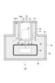
- first insulating member 73 in the space between the X-ray generating tube 1 and the first portion 52, i.e., the second space SP2, as shown in FIG. 8.
- the first insulating member 73 can be arranged at a distance from the first portion 52 and the X-ray generating tube 1.
- the first insulating member 73 may be coupled to a third insulating member 77 arranged in the first space SP1 so as to surround the drive circuit 40.
- the third insulating member 77 can be arranged at a distance from the storage container 50.
- the first insulating member 73 and the third insulating member 77 may be made of any one of polytetrafluoroethylene, PMMA (polymethylmethacrylate resin), epoxy resin, polycarbonate, glass, and ceramics.
- the first insulating member 73 and the third insulating member 77 may be made of a resin-impregnated glass cloth laminate (e.g., a laminated plate, a laminated pipe) that has been heated and pressed.
- the resin-impregnated glass cloth laminate may be made by, for example, laminating or winding a member (prepreg) in which a resin such as epoxy resin or phenolic resin is impregnated on a glass nonwoven fabric, and then performing heating and pressing.
- the first insulating member 73 and the third insulating member 77 may be made of, for example, glass epoxy.
- the first insulating member 73 and the third insulating member 77 preferably have an insulating property of 1 ⁇ 10 5 ⁇ m or more in volume resistance at 25° C.
- the area in which the first insulating member 73 is disposed is limited, and the second insulating member 74 is added.
- the second space SP2 is defined as a space including the third space SP3 and the fourth space SP4.
- the third space SP3 is a space into which the X-rays (rear X-rays 105) from the target 23 enter without being blocked by either the cathode 30 or the anode 20.
- the fourth space SP4 is a space into which the X-rays (rear X-rays 105) from the target 23 are blocked by either the cathode 30 (including the electron emission portion 32) or the anode 20 (i.e., a space into which the X-rays from the target 23 do not enter).
- the first insulating member 73 is disposed in the fourth space SP4, away from the insulating tube 10 and the container 50, so as to surround the insulating tube 10, and the first insulating member 73 is not disposed in the third space SP3.
- the outer surface 14 of the insulating tube 10 has a first region R1 that is not surrounded by the first insulating member 73, and the first region R1 is surrounded by a second insulating member 74 that is arranged so as to contact the first region R1.
- the entire first region R1 is surrounded by the second insulating member 74.
- the rear X-rays 105 include not only X-rays that arrive directly from the target 23, but also X-rays reflected by members such as the cathode 30 and the anode 20.
- the outer surface 14 of the insulating tube 10 has a second region R2 between the first region R1 and the cathode 30, and the first insulating member 73 can be arranged to surround the entire second region R2.
- the first insulating member 73 can be arranged to extend from a fourth space SP4, which is part of the second space SP2, to the first space SP1.
- the second insulating member 74 can include a ring-shaped portion.
- the second insulating member 74 can be made of polytetrafluoroethylene, PMMA (polymethylmethacrylate resin), or epoxy resin.
- the second insulating member 74 is preferably arranged so as to cover the contact portion (boundary) between the cathode 30 and the insulating tube 10.
- the second insulating member 74 can be arranged so as to cover at least a portion of the cathode 30, preferably the entire cathode 30.
- the second insulating member 74 is preferably arranged so as to cover the entire outer surface 14 of the insulating tube 10.
- the second insulating member 74 can be arranged to cover the outer surface 14 of the insulating tube 10 or in the first region R1 by a molding method, a spraying method, a dipping method, or the like, in the same manner as the member 72 of the first embodiment.
- the second insulating member 74 may be molded using a mold separately from other members, i.e., as a single unit, or may be molded integrally with the insulating tube 10 using a mold as in insert molding.
- the manufacturing method of the X-ray generating device 100 as illustrated in FIG. 8 may include a step of inserting a first insulating member 73 into the gap between the X-ray generating tube 1 and the first part 52.
- a step of inserting a first insulating member 73 into the gap between the X-ray generating tube 1 and the first part 52 if the first insulating member 73 comes into contact with or collides with the X-ray generating tube 1 or the first part 52, these members may be deformed or particles may be generated due to friction. Such deformation and generation of particles may reduce the pressure resistance performance and cause abnormal discharge.
- the entire insulating tube 10 (or X-ray generating tube 1) may be disposed in the second space SP2.
- the dimensions of the insulating tube 10 (or X-ray generating tube 1) may be smaller than the dimensions of the first portion 52 in the direction in which electrons are emitted (the axial direction of the X-ray generating tube 1).
- the cable 42 may be present on the boundary between the first space SP1 and the second space SP2.
- insulation measures may also be taken between the cathode 30 and the anode 20, as in the first and fourth embodiments.
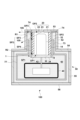
- FIG. 12 exemplarily and diagrammatically illustrates the configuration of the X-ray generating device 100 of the sixth embodiment. Matters not mentioned in the description of the sixth embodiment may follow the basic configuration described with reference to the first to fifth embodiments or FIG. 1.
- the arrangement area of the first insulating member 73 is limited to suppress abnormal discharge caused by the rear X-rays 105.
- abnormal discharge caused by the rear X-rays 105 is suppressed without limiting the arrangement area of the first insulating member 73 (insulating partition).
- an X-ray shielding member 80 is provided.
- the X-ray shielding member 80 may be arranged so that a portion of the outer surface 14 of the insulating tube 10 is surrounded by the X-ray shielding member 80.
- the X-ray shielding member 80 may extend from the anode 20 toward the cathode 30 (the blocking member 31) so as to block X-rays (rear X-rays 105).
- the X-ray shielding member 80 can be arranged to extend from the anode 20 to a position between the anode 20 and the cathode 30 (the blocking member 31).
- the third space SP3 described above i.e., the space into which the X-rays (rear X-rays 105) from the target 23 enter without being blocked by either the cathode 30 or the anode 20, can be eliminated or reduced.
- the X-ray shielding member 80 is preferably at the same potential as the anode 20 (electrically connected to the anode 20) from the viewpoint of stabilizing the potential of the X-ray shielding member 80, but may be at a different potential.
- the X-ray shielding member 80 is preferably made of a material that easily blocks X-rays, particularly a metal material.
- the X-ray shielding member 80 may be made of a bulk metal material or a metal thin film of 100 ⁇ m or less. Since a gap between the X-ray shielding member 80 and the insulating tube 10 may cause insulation breakdown, the X-ray shielding member 80 may be disposed so as to contact the outer surface 14 of the insulating tube 10.
- the X-ray shielding member 80 may be formed by a plating method or a PVD method so as to contact the outer surface 14 of the insulating tube 10, for example.
- a potential different from that of the cathode 30 may be applied to the X-ray shielding member 80, for example, the potential of the anode 20 may be applied to the X-ray shielding member 80.
- the creepage distance between the cathode 30 and the X-ray shielding member 80 becomes shorter than the creepage distance between the cathode 30 and the anode 20 when the X-ray shielding member 80 is not provided. This may cause abnormal discharge to occur. Therefore, it is preferable that the X-ray shielding member 80 is covered with an insulating member 74.
- the insulating member 74 may be arranged so as to cover the contact portion (boundary) between the X-ray shielding member 80 and the insulating tube 10.
- the insulating member 74 may also be arranged so as to cover the exposed portion (portion not covered by the X-ray shielding member 80) of the outer surface 14 of the insulating tube 10.
- the insulating member 74 may be arranged so as to cover the entire X-ray shielding member 80 and the entire exposed portion of the outer surface 14 of the insulating tube 10.
- the insulating member 74 can be arranged so as to cover the contact portion (boundary) between the cathode 30 (the blocking member 31) and the insulating tube 10.
- the insulating member 74 can be arranged so as to contact the outer surface of the X-ray shielding member 80.
- the outer surface 34 of the cathode 30 (the blocking member 31) has a cylindrical side surface and a circular bottom surface, and at least the entire side surface of the outer surface 34 of the cathode 30 can be covered by the insulating member 74. Furthermore, it is preferable that the entire outer surface 34 of the cathode 30 is covered by the insulating member 74.
- a first insulating member 73 (insulating partition) may be arranged at a distance from the insulating tube 10 and the container 50 so as to surround the insulating tube 10 and the insulating member 74, but the first insulating member 73 does not have to be arranged. If the first insulating member 73 is not arranged, the X-ray shielding member 80 can suppress abnormal discharge caused by the rear X-rays 105 charging the first part 52 of the container 50 (for example, when the first part 52 is made of an insulator, or when the first part 52 is made of a conductor but is in a floating state), the insulating liquid 60, and the second insulating member 74.
- the X-ray shielding member 80 does not need to block all of the rear X-rays 105. Extending the X-ray shielding member 80 toward the cathode 30 can act to shorten the creepage distance. Therefore, the extension range of the X-ray shielding member 80, or the range in which the X-ray shielding member 80 covers the insulating tube 10, can be determined taking into account both the disadvantage of shortening the creepage distance and the advantage of blocking the rear X-rays 105. From another perspective, the extension range of the X-ray shielding member 80 can be determined according to the intensity distribution of the rear X-rays 105.
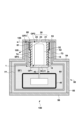
- the outer surface 14 of the insulating tube 10 is surrounded by an insulating member 74, and an adhesion layer 81 is provided between the outer surface 14 of the insulating tube 10 and the insulating member 74.
- an adhesion layer 81 By providing the adhesion layer 81, the adhesion between the outer surface 14 of the insulating tube 10 and the insulating member 74 is improved.
- the insulating member 74 can be arranged so as to cover the boundary between the cathode 30 (the blocking member 31) and the insulating tube 10.
- the adhesion layer 81 and the insulating member 74 can be arranged so as to cover the entire outer surface 34 of the insulating tube 10.
- the adhesion layer 81 can be made of, for example, a silane coupling agent.
- the adhesion layer 81 may be made of a titanium coupling agent.
- the seventh embodiment of the X-ray generating device 100 may include the X-ray shielding member 80 described in the sixth embodiment.
- the adhesion layer 81 may also be disposed between the insulating member 74 and the X-ray shielding member 80.
- the outer surface 14 of the insulating tube 10 is surrounded by an insulating member 74, and an adhesion layer 81 is provided between the outer surface 14 of the insulating tube 10 and the insulating member 74.
- an adhesion layer 81 By providing the adhesion layer 81, the adhesion between the outer surface 14 of the insulating tube 10 and the insulating member 74 is improved.
- the insulating member 74 can be arranged so as to cover the boundary between the cathode 30 (the blocking member 31) and the insulating tube 10.
- the adhesion layer 81 and the insulating member 74 can be arranged so as to cover the entire outer surface 34 of the insulating tube 10.
- the adhesion layer 81 can be made of, for example, a silane coupling agent.
- the adhesion layer 81 may be made of a titanium coupling agent.
- the X-ray generating device 100 does not include the first insulating member 73, the third insulating member 77, and the X-ray shielding member 80. However, by providing an adhesion layer 81 between the outer surface 14 of the insulating tube 10 and the insulating member 74, the occurrence of abnormal discharge can be reduced.
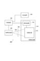
- the X-ray imaging device 200 may include an X-ray generating device 100 and an X-ray detecting device 110 that detects X-rays 104 emitted from the X-ray generating device 100 and transmitted through an object 106.
- the X-ray imaging device 200 may further include a control device 120 and a display device 130.
- the X-ray detecting device 110 may include an X-ray detector 112 and a signal processing device 114.
- the control device 120 may control the X-ray generating device 100 and the X-ray detecting device 110.
- the X-ray detector 112 detects or captures the X-rays 104 emitted from the X-ray generating device 100 and transmitted through an object 106.
- the signal processing device 114 may process the signal output from the X-ray detector 112 and supply the processed signal to the control device 120.
- the control device 120 causes the display device 130 to display an image based on the signal supplied from the signal processing device 114.
Landscapes
- Physics & Mathematics (AREA)
- Health & Medical Sciences (AREA)
- Life Sciences & Earth Sciences (AREA)
- Chemical & Material Sciences (AREA)
- Analytical Chemistry (AREA)
- Biochemistry (AREA)
- General Health & Medical Sciences (AREA)
- General Physics & Mathematics (AREA)
- Immunology (AREA)
- Pathology (AREA)
- X-Ray Techniques (AREA)
Priority Applications (6)
| Application Number | Priority Date | Filing Date | Title |
|---|---|---|---|
| JP2024572989A JPWO2024157842A1 (https=) | 2023-01-25 | 2024-01-16 | |
| KR1020257027237A KR20250135857A (ko) | 2023-01-25 | 2024-01-16 | X선 발생 장치 및 x선 촬상 장치 |
| EP24747173.3A EP4657487A1 (en) | 2023-01-25 | 2024-01-16 | X-ray generation device and x-ray imaging device |
| CN202480009034.9A CN120604315A (zh) | 2023-01-25 | 2024-01-16 | X射线生成装置和x射线成像装置 |
| TW113102710A TW202503808A (zh) | 2023-01-25 | 2024-01-24 | X射線產生裝置及x射線攝像裝置 |
| US19/277,242 US20250351256A1 (en) | 2023-01-25 | 2025-07-22 | X-ray generation apparatus and x-ray imaging apparatus |
Applications Claiming Priority (4)
| Application Number | Priority Date | Filing Date | Title |
|---|---|---|---|
| JPPCT/JP2023/002275 | 2023-01-25 | ||
| PCT/JP2023/002275 WO2024157394A1 (ja) | 2023-01-25 | 2023-01-25 | X線発生装置およびx線撮像装置 |
| PCT/JP2023/033426 WO2024157531A1 (ja) | 2023-01-25 | 2023-09-13 | X線発生装置およびx線撮像装置 |
| JPPCT/JP2023/033426 | 2023-09-13 |
Related Child Applications (1)
| Application Number | Title | Priority Date | Filing Date |
|---|---|---|---|
| US19/277,242 Continuation US20250351256A1 (en) | 2023-01-25 | 2025-07-22 | X-ray generation apparatus and x-ray imaging apparatus |
Publications (1)
| Publication Number | Publication Date |
|---|---|
| WO2024157842A1 true WO2024157842A1 (ja) | 2024-08-02 |
Family
ID=91067372
Family Applications (1)
| Application Number | Title | Priority Date | Filing Date |
|---|---|---|---|
| PCT/JP2024/000981 Ceased WO2024157842A1 (ja) | 2023-01-25 | 2024-01-16 | X線発生装置およびx線撮像装置 |
Country Status (7)
| Country | Link |
|---|---|
| US (2) | US20250351256A1 (https=) |
| EP (1) | EP4657487A1 (https=) |
| JP (2) | JP7486694B1 (https=) |
| KR (2) | KR20250135849A (https=) |
| CN (2) | CN120584548A (https=) |
| TW (2) | TW202503807A (https=) |
| WO (1) | WO2024157842A1 (https=) |
Families Citing this family (2)
| Publication number | Priority date | Publication date | Assignee | Title |
|---|---|---|---|---|
| JP7484032B1 (ja) | 2023-01-25 | 2024-05-15 | キヤノンアネルバ株式会社 | X線発生装置およびx線撮像装置 |
| WO2025057338A1 (ja) * | 2023-09-13 | 2025-03-20 | キヤノンアネルバ株式会社 | X線発生装置およびx線撮像装置 |
Citations (5)
| Publication number | Priority date | Publication date | Assignee | Title |
|---|---|---|---|---|
| JP2014154423A (ja) * | 2013-02-12 | 2014-08-25 | Toshiba Corp | X線発生装置 |
| JP2015015227A (ja) * | 2013-06-05 | 2015-01-22 | キヤノン株式会社 | 放射線発生管及びそれを用いた放射線発生装置と放射線撮影システム |
| JP2016103451A (ja) | 2014-11-28 | 2016-06-02 | キヤノン株式会社 | X線発生管、x線発生装置およびx線撮影システム |
| JP2018073625A (ja) * | 2016-10-28 | 2018-05-10 | キヤノン株式会社 | X線発生装置及び、x線撮影システム |
| WO2020136911A1 (ja) * | 2018-12-28 | 2020-07-02 | キヤノンアネルバ株式会社 | X線発生管、x線発生装置およびx線撮像装置 |
Family Cites Families (6)
| Publication number | Priority date | Publication date | Assignee | Title |
|---|---|---|---|---|
| JP5921153B2 (ja) * | 2011-11-09 | 2016-05-24 | キヤノン株式会社 | 放射線発生管および放射線発生装置 |
| JP6415250B2 (ja) * | 2014-10-29 | 2018-10-31 | キヤノン株式会社 | X線発生管、x線発生装置及びx線撮影システム |
| KR102362008B1 (ko) * | 2019-04-15 | 2022-02-14 | 캐논 아네르바 가부시키가이샤 | X선 발생 장치 및 x선 촬영 장치 |
| JP6792676B1 (ja) * | 2019-07-24 | 2020-11-25 | 浜松ホトニクス株式会社 | X線管 |
| JP6683903B1 (ja) * | 2019-09-03 | 2020-04-22 | キヤノンアネルバ株式会社 | X線発生装置およびx線撮像装置 |
| WO2021044525A1 (ja) * | 2019-09-03 | 2021-03-11 | キヤノンアネルバ株式会社 | X線発生装置およびx線撮影装置 |
-
2023
- 2023-09-13 JP JP2024506267A patent/JP7486694B1/ja active Active
- 2023-09-13 CN CN202380092271.1A patent/CN120584548A/zh active Pending
- 2023-09-13 KR KR1020257027165A patent/KR20250135849A/ko active Pending
-
2024
- 2024-01-16 CN CN202480009034.9A patent/CN120604315A/zh active Pending
- 2024-01-16 WO PCT/JP2024/000981 patent/WO2024157842A1/ja not_active Ceased
- 2024-01-16 JP JP2024572989A patent/JPWO2024157842A1/ja active Pending
- 2024-01-16 KR KR1020257027237A patent/KR20250135857A/ko active Pending
- 2024-01-16 EP EP24747173.3A patent/EP4657487A1/en active Pending
- 2024-01-24 TW TW113102709A patent/TW202503807A/zh unknown
- 2024-01-24 TW TW113102710A patent/TW202503808A/zh unknown
-
2025
- 2025-07-22 US US19/277,242 patent/US20250351256A1/en active Pending
- 2025-07-22 US US19/276,911 patent/US20250349489A1/en active Pending
Patent Citations (5)
| Publication number | Priority date | Publication date | Assignee | Title |
|---|---|---|---|---|
| JP2014154423A (ja) * | 2013-02-12 | 2014-08-25 | Toshiba Corp | X線発生装置 |
| JP2015015227A (ja) * | 2013-06-05 | 2015-01-22 | キヤノン株式会社 | 放射線発生管及びそれを用いた放射線発生装置と放射線撮影システム |
| JP2016103451A (ja) | 2014-11-28 | 2016-06-02 | キヤノン株式会社 | X線発生管、x線発生装置およびx線撮影システム |
| JP2018073625A (ja) * | 2016-10-28 | 2018-05-10 | キヤノン株式会社 | X線発生装置及び、x線撮影システム |
| WO2020136911A1 (ja) * | 2018-12-28 | 2020-07-02 | キヤノンアネルバ株式会社 | X線発生管、x線発生装置およびx線撮像装置 |
Non-Patent Citations (1)
| Title |
|---|
| See also references of EP4657487A1 |
Also Published As
| Publication number | Publication date |
|---|---|
| US20250351256A1 (en) | 2025-11-13 |
| CN120604315A (zh) | 2025-09-05 |
| US20250349489A1 (en) | 2025-11-13 |
| TW202503807A (zh) | 2025-01-16 |
| JP7486694B1 (ja) | 2024-05-17 |
| JPWO2024157531A1 (https=) | 2024-08-02 |
| TW202503808A (zh) | 2025-01-16 |
| KR20250135857A (ko) | 2025-09-15 |
| JPWO2024157842A1 (https=) | 2024-08-02 |
| EP4657487A1 (en) | 2025-12-03 |
| CN120584548A (zh) | 2025-09-02 |
| KR20250135849A (ko) | 2025-09-15 |
Similar Documents
| Publication | Publication Date | Title |
|---|---|---|
| JP7784027B2 (ja) | X線発生装置およびx線撮像装置 | |
| WO2024157842A1 (ja) | X線発生装置およびx線撮像装置 |
Legal Events
| Date | Code | Title | Description |
|---|---|---|---|
| 121 | Ep: the epo has been informed by wipo that ep was designated in this application |
Ref document number: 24747173 Country of ref document: EP Kind code of ref document: A1 |
|
| ENP | Entry into the national phase |
Ref document number: 2024572989 Country of ref document: JP Kind code of ref document: A |
|
| WWE | Wipo information: entry into national phase |
Ref document number: 2024572989 Country of ref document: JP |
|
| WWE | Wipo information: entry into national phase |
Ref document number: 202480009034.9 Country of ref document: CN |
|
| ENP | Entry into the national phase |
Ref document number: 1020257027237 Country of ref document: KR Free format text: ST27 STATUS EVENT CODE: A-0-1-A10-A15-NAP-PA0105 (AS PROVIDED BY THE NATIONAL OFFICE) |
|
| WWE | Wipo information: entry into national phase |
Ref document number: 1020257027237 Country of ref document: KR |
|
| NENP | Non-entry into the national phase |
Ref country code: DE |
|
| WWP | Wipo information: published in national office |
Ref document number: 202480009034.9 Country of ref document: CN |
|
| WWP | Wipo information: published in national office |
Ref document number: 2024747173 Country of ref document: EP |