WO2024157772A1 - センサ素子及びガスセンサ - Google Patents
センサ素子及びガスセンサ Download PDFInfo
- Publication number
- WO2024157772A1 WO2024157772A1 PCT/JP2024/000357 JP2024000357W WO2024157772A1 WO 2024157772 A1 WO2024157772 A1 WO 2024157772A1 JP 2024000357 W JP2024000357 W JP 2024000357W WO 2024157772 A1 WO2024157772 A1 WO 2024157772A1
- Authority
- WO
- WIPO (PCT)
- Prior art keywords
- measurement
- electrode
- internal space
- pump
- gas
- Prior art date
- Legal status (The legal status is an assumption and is not a legal conclusion. Google has not performed a legal analysis and makes no representation as to the accuracy of the status listed.)
- Ceased
Links
Images
Classifications
-
- G—PHYSICS
- G01—MEASURING; TESTING
- G01N—INVESTIGATING OR ANALYSING MATERIALS BY DETERMINING THEIR CHEMICAL OR PHYSICAL PROPERTIES
- G01N27/00—Investigating or analysing materials by the use of electric, electrochemical, or magnetic means
- G01N27/26—Investigating or analysing materials by the use of electric, electrochemical, or magnetic means by investigating electrochemical variables; by using electrolysis or electrophoresis
- G01N27/403—Cells and electrode assemblies
- G01N27/406—Cells and probes with solid electrolytes
- G01N27/407—Cells and probes with solid electrolytes for investigating or analysing gases
- G01N27/409—Oxygen concentration cells
-
- G—PHYSICS
- G01—MEASURING; TESTING
- G01N—INVESTIGATING OR ANALYSING MATERIALS BY DETERMINING THEIR CHEMICAL OR PHYSICAL PROPERTIES
- G01N27/00—Investigating or analysing materials by the use of electric, electrochemical, or magnetic means
- G01N27/26—Investigating or analysing materials by the use of electric, electrochemical, or magnetic means by investigating electrochemical variables; by using electrolysis or electrophoresis
- G01N27/416—Systems
- G01N27/417—Systems using cells, i.e. more than one cell and probes with solid electrolytes
-
- G—PHYSICS
- G01—MEASURING; TESTING
- G01N—INVESTIGATING OR ANALYSING MATERIALS BY DETERMINING THEIR CHEMICAL OR PHYSICAL PROPERTIES
- G01N27/00—Investigating or analysing materials by the use of electric, electrochemical, or magnetic means
- G01N27/26—Investigating or analysing materials by the use of electric, electrochemical, or magnetic means by investigating electrochemical variables; by using electrolysis or electrophoresis
- G01N27/403—Cells and electrode assemblies
- G01N27/406—Cells and probes with solid electrolytes
- G01N27/407—Cells and probes with solid electrolytes for investigating or analysing gases
- G01N27/41—Oxygen pumping cells
-
- G—PHYSICS
- G01—MEASURING; TESTING
- G01N—INVESTIGATING OR ANALYSING MATERIALS BY DETERMINING THEIR CHEMICAL OR PHYSICAL PROPERTIES
- G01N27/00—Investigating or analysing materials by the use of electric, electrochemical, or magnetic means
- G01N27/26—Investigating or analysing materials by the use of electric, electrochemical, or magnetic means by investigating electrochemical variables; by using electrolysis or electrophoresis
- G01N27/416—Systems
- G01N27/417—Systems using cells, i.e. more than one cell and probes with solid electrolytes
- G01N27/419—Measuring voltages or currents with a combination of oxygen pumping cells and oxygen concentration cells
Definitions
- the present invention relates to a sensor element and a gas sensor.
- Patent Document 1 describes a gas sensor having a sensor element including an element body having a measured gas flow section that includes an oxygen ion conductive solid electrolyte layer and introduces and flows the measured gas, an adjustment pump cell that adjusts the oxygen concentration in an oxygen concentration adjustment chamber in the measured gas flow section, a measurement pump cell that has a measurement electrode disposed in a measurement chamber downstream of the oxygen concentration adjustment chamber in the measured gas flow section and pumps out oxygen around the measurement electrode, and a reference electrode disposed inside the element body so as to come into contact with a reference gas that serves as a reference for detecting the concentration of a specific gas in the measured gas.
- Patent Document 1 When detecting the concentration of NOx with this gas sensor, first, the oxygen concentration of the measured gas in the oxygen concentration adjustment chamber is adjusted by the adjustment pump cell. Next, the NOx in the measured gas after the oxygen concentration is adjusted is reduced in the measurement chamber. The measurement pump cell is controlled to pump oxygen from the measurement chamber so that the measurement voltage between the reference electrode and the measurement electrode becomes the normal target value, and the concentration of NOx in the measurement gas is detected based on the pump current Ip2 flowing through the measurement pump cell at this time.
- Patent Document 1 also describes a startup measurement pump control process that controls the measurement pump cell to pump oxygen from the measurement chamber so that the measurement voltage becomes a startup target value higher than the normal target value when the sensor element is started.
- the light-off time of the sensor element can be shortened.
- the light-off time is the time from the start of the sensor element startup until the value of the pump current Ip2 becomes a value corresponding to the NOx concentration in the measurement gas.
- the light-off time varies depending on the length of time required to remove oxygen from the measurement chamber before the sensor element is started.
- the smaller the volume of the measurement electrode the shorter the light-off time tends to be, regardless of whether the startup measurement pump control process described above is performed.
- the smaller the volume of the measurement electrode the more likely it is that the measurement electrode will deteriorate.
- the present invention was made to solve these problems, and its main objective is to prevent the light-off time from becoming longer while suppressing deterioration of the measurement electrode.
- the present invention takes the following measures to achieve the above-mentioned main objective.
- the volume ratio Fv corresponds to the ratio between the volume Ve of the measurement electrode and the volume of the space in the measurement chamber.
- the volume ratio Fv is 0.05 or more, so that the deterioration of the measurement electrode can be suppressed.
- the volume ratio Fv is 0.21 or less, so that the light-off time can be suppressed from becoming longer.
- the inventors have confirmed these things through experiments, analysis, and the like. Therefore, in this sensor element, it is possible to suppress the light-off time from becoming longer while suppressing the deterioration of the measurement electrode.
- the measurement electrode may contain at least one of Pt and Rh.
- the oxygen concentration adjustment chamber may include a first internal cavity and a second internal cavity disposed downstream of the first internal cavity
- the inner adjustment electrode may include a main pump electrode disposed in the first internal cavity and an auxiliary pump electrode disposed in the second internal cavity
- the adjustment pump cell may include a main pump cell having the main pump electrode and adjusting the oxygen concentration in the first internal cavity, and an auxiliary pump cell having the auxiliary pump electrode and adjusting the oxygen concentration in the second internal cavity.
- the gas sensor of the present invention is equipped with a sensor element according to any one of [1] to [6] above. Therefore, this gas sensor can obtain the same effects as the sensor element described above, for example, the effect of suppressing deterioration of the measurement electrode while suppressing an increase in the light-off time.
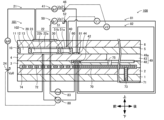
- FIG. 1 is a schematic cross-sectional view illustrating an example of the configuration of a gas sensor 100.
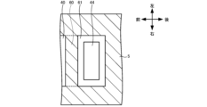
- FIG. 2 is a partially enlarged top view of the periphery of a measurement electrode 44 in the spacer layer 5 of FIG. 1 .
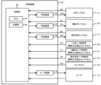
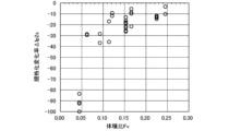
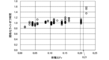
- FIG. 4 is a block diagram showing the electrical connection between a control device 95 and each cell, etc. 13 is a graph showing the relationship between the volume ratio Fv and the normalized rate of change ⁇ Ip2s. 1 is a graph showing the relationship between the volume ratio Fv and the normalized light-off time.
- FIG. 1 is a schematic cross-sectional view showing an example of the configuration of a gas sensor 100 according to an embodiment of the present invention.
- FIG. 2 is a partially enlarged view of the periphery of the measurement electrode 44 of the spacer layer 5 in FIG. 1 as viewed from above.
- the fourth diffusion-controlling portion 60 is shown by a dotted line for reference.
- FIG. 3 is a block diagram showing the electrical connection relationship between the control device 95 and each cell and the heater 72.
- This gas sensor 100 is attached to a pipe such as an exhaust gas pipe of an internal combustion engine.
- the gas sensor 100 detects a specific gas concentration, which is the concentration of a specific gas such as NOx or ammonia in the measured gas, using the exhaust gas of the internal combustion engine as the measured gas.
- the gas sensor 100 measures the NOx concentration as the specific gas concentration.
- the gas sensor 100 includes a sensor element 101 having an element body 102 in the shape of a long rectangular parallelepiped, each of the cells 21, 41, 50, 80 to 83 included in the sensor element 101, a heater section 70 provided inside the sensor element 101, and a control device 95 that has variable power sources 24, 46, 52 and a heater power source 76 and controls the entire gas sensor 100.
- the element body 102 is a laminate in which six layers, namely a first substrate layer 1, a second substrate layer 2, a third substrate layer 3, a first solid electrolyte layer 4, a spacer layer 5, and a second solid electrolyte layer 6, each of which is made of an oxygen ion conductive solid electrolyte layer such as zirconia (ZrO2), are laminated in this order from the bottom as viewed in the drawing.
- the solid electrolyte forming these six layers is dense and airtight.
- the element body 102 is manufactured, for example, by performing a predetermined processing and printing a circuit pattern on ceramic green sheets corresponding to each layer, laminating them, and further firing them to integrate them.
- the gas inlet 10 On the tip side (left end side in FIG. 1) of the sensor element 101 (element body 102), between the lower surface of the second solid electrolyte layer 6 and the upper surface of the first solid electrolyte layer 4, the gas inlet 10, the first diffusion rate-controlling section 11, the buffer space 12, the second diffusion rate-controlling section 13, the first internal cavity (oxygen concentration adjustment chamber) 20, the third diffusion rate-controlling section 30, the second internal cavity (oxygen concentration adjustment chamber) 40, the fourth diffusion rate-controlling section 60, and the third internal cavity (measurement chamber) 61 are adjacently formed and communicated in this order.
- the gas inlet 10, buffer space 12, first internal cavity 20, second internal cavity 40, and third internal cavity 61 are spaces inside the sensor element 101, which are defined by a hollowed-out portion of the spacer layer 5, with an upper portion defined by the underside of the second solid electrolyte layer 6, a lower portion defined by the upper surface of the first solid electrolyte layer 4, and a side portion defined by the side surface of the spacer layer 5.
- the first diffusion rate-controlling section 11, the second diffusion rate-controlling section 13, and the third diffusion rate-controlling section 30 are each provided as two horizontally elongated slits (with the opening extending in the direction perpendicular to the drawing).
- the fourth diffusion rate-controlling section 60 is provided as a single horizontally elongated slit (with the opening extending in the direction perpendicular to the drawing) formed as a gap with the underside of the second solid electrolyte layer 6.
- the area extending from the gas inlet 10 to the third internal space 61 is also referred to as the measured gas flow section.
- the sensor element 101 (element body 102) is provided with a reference gas inlet 49 that allows a reference gas to flow from the outside of the sensor element 101 to the reference electrode 42 when measuring the NOx concentration.
- the reference gas inlet 49 has a reference gas inlet space 43 and a reference gas inlet layer 48.
- the reference gas inlet space 43 is a space provided inward from the rear end surface of the sensor element 101.
- the reference gas inlet space 43 is provided between the upper surface of the third substrate layer 3 and the lower surface of the spacer layer 5, at a position defined by the side surface of the first solid electrolyte layer 4.
- the reference gas inlet space 43 opens at the rear end surface of the sensor element 101, and this opening functions as an inlet portion 49a of the reference gas inlet 49.
- the reference gas is introduced into the reference gas inlet space 43 from this inlet portion 49a.
- the reference gas inlet 49 introduces the reference gas introduced from the inlet portion 49a into the reference electrode 42 while providing a predetermined diffusion resistance to the reference gas introduced from the inlet portion 49a.
- the reference gas is air.
- the reference gas introduction layer 48 is provided between the upper surface of the third substrate layer 3 and the lower surface of the first solid electrolyte layer 4.
- the reference gas introduction layer 48 is a porous body made of ceramics such as alumina. A portion of the upper surface of the reference gas introduction layer 48 is exposed in the reference gas introduction space 43.
- the reference gas introduction layer 48 is formed so as to cover the reference electrode 42.
- the reference gas introduction layer 48 allows the reference gas to flow from the reference gas introduction space 43 to the reference electrode 42.
- the reference electrode 42 is an electrode formed in such a manner that it is sandwiched between the upper surface of the third substrate layer 3 and the first solid electrolyte layer 4, and as described above, a reference gas introduction layer 48 that is connected to the reference gas introduction space 43 is provided around it.
- a reference gas introduction layer 48 that is connected to the reference gas introduction space 43 is provided around it.
- the gas inlet 10 is a section that opens to the external space, and the measured gas is taken into the sensor element 101 from the external space through the gas inlet 10.
- the first diffusion rate-controlling section 11 is a section that imparts a predetermined diffusion resistance to the measured gas taken in from the gas inlet 10.
- the buffer space 12 is a space provided to guide the measured gas introduced from the first diffusion rate-controlling section 11 to the second diffusion rate-controlling section 13.
- the second diffusion rate-controlling section 13 is a section that imparts a predetermined diffusion resistance to the measured gas introduced from the buffer space 12 into the first internal space 20.
- the first internal space 20 is provided as a space for adjusting the oxygen partial pressure in the measurement gas introduced through the second diffusion rate-controlling section 13. The oxygen partial pressure is adjusted by the operation of the main pump cell 21.
- the main pump cell 21 is an electrochemical pump cell that is composed of an inner pump electrode 22 having a ceiling electrode portion 22a provided on almost the entire lower surface of the second solid electrolyte layer 6 facing the first internal space 20, an outer pump electrode 23 provided in a region corresponding to the ceiling electrode portion 22a on the upper surface of the second solid electrolyte layer 6 in a manner that exposes it to the outside of the sensor element 101, and the second solid electrolyte layer 6, spacer layer 5, and first solid electrolyte layer 4 that form a current path between these electrodes.
- the inner pump electrode 22 is formed across the upper and lower solid electrolyte layers (second solid electrolyte layer 6 and first solid electrolyte layer 4) that define the first internal cavity 20, and the spacer layer 5 that provides the side walls. Specifically, a ceiling electrode portion 22a is formed on the lower surface of the second solid electrolyte layer 6 that provides the ceiling surface of the first internal cavity 20, and a bottom electrode portion 22b is formed on the upper surface of the first solid electrolyte layer 4 that provides the bottom surface.
- Side electrode portions are formed on the side wall surfaces (inner surfaces) of the spacer layer 5 that constitute both side wall portions of the first internal cavity 20 so as to connect the ceiling electrode portion 22a and the bottom electrode portion 22b, and are arranged in a tunnel-shaped structure at the locations where the side electrode portions are arranged.
- an electrochemical sensor cell i.e., an oxygen partial pressure detection sensor cell 80 for controlling the main pump, is configured by the inner pump electrode 22, the second solid electrolyte layer 6, the spacer layer 5, the first solid electrolyte layer 4, the third substrate layer 3, and the reference electrode 42.
- the oxygen concentration (oxygen partial pressure) in the first internal space 20 can be determined by measuring the electromotive force (voltage V0) in the oxygen partial pressure detection sensor cell 80 for controlling the main pump. Furthermore, the pump current Ip0 is controlled by feedback controlling the voltage Vp0 of the variable power supply 24 so that the voltage V0 becomes the target value. This allows the oxygen concentration in the first internal space 20 to be maintained at a predetermined constant value.
- the third diffusion rate control section 30 is a section that imparts a predetermined diffusion resistance to the measured gas, the oxygen concentration (oxygen partial pressure) of which is controlled by the operation of the main pump cell 21 in the first internal space 20, and guides the measured gas to the second internal space 40.
- the second internal space 40 is provided as a space for further adjusting the oxygen partial pressure by the auxiliary pump cell 50 for the measurement gas introduced through the third diffusion-controlling section 30 after the oxygen concentration (oxygen partial pressure) has been adjusted in advance in the first internal space 20. This allows the oxygen concentration in the second internal space 40 to be kept constant with high precision, making it possible for the gas sensor 100 to measure NOx concentrations with high precision.
- the auxiliary pump cell 50 is an auxiliary electrochemical pump cell that is composed of an auxiliary pump electrode 51 having a ceiling electrode portion 51a provided on almost the entire lower surface of the second solid electrolyte layer 6 facing the second internal space 40, an outer pump electrode 23 (not limited to the outer pump electrode 23, any suitable electrode on the outside of the sensor element 101 will suffice), the second solid electrolyte layer 6, the spacer layer 5, and the first solid electrolyte layer 4.
- the auxiliary pump electrode 51 is disposed in the second internal space 40 in a tunnel-shaped structure similar to the inner pump electrode 22 disposed in the first internal space 20. That is, a ceiling electrode portion 51a is formed on the second solid electrolyte layer 6 that provides the ceiling surface of the second internal space 40, and a bottom electrode portion 51b is formed on the first solid electrolyte layer 4 that provides the bottom surface of the second internal space 40. Side electrode portions (not shown) that connect the ceiling electrode portion 51a and the bottom electrode portion 51b are formed on both wall surfaces of the spacer layer 5 that provides the side walls of the second internal space 40, forming a tunnel-shaped structure.
- auxiliary pump cell 50 by applying a desired voltage Vp1 between the auxiliary pump electrode 51 and the outer pump electrode 23, it is possible to pump oxygen in the atmosphere in the second internal space 40 out to the external space, or pump oxygen from the external space into the second internal space 40.
- an electrochemical sensor cell i.e., an oxygen partial pressure detection sensor cell 81 for controlling the auxiliary pump, is constituted by the auxiliary pump electrode 51, the reference electrode 42, the second solid electrolyte layer 6, the spacer layer 5, the first solid electrolyte layer 4, and the third substrate layer 3.
- the auxiliary pump cell 50 pumps using a variable power supply 52 whose voltage is controlled based on the electromotive force (voltage V1) detected by the auxiliary pump control oxygen partial pressure detection sensor cell 81. This allows the oxygen partial pressure in the atmosphere within the second internal space 40 to be controlled to a low partial pressure that does not substantially affect the measurement of NOx.
- the pump current Ip1 is used to control the electromotive force of the oxygen partial pressure detection sensor cell 80 for controlling the main pump.
- the pump current Ip1 is input as a control signal to the oxygen partial pressure detection sensor cell 80 for controlling the main pump, and the above-mentioned target value of the voltage V0 is controlled so that the gradient of the oxygen partial pressure in the measurement gas introduced from the third diffusion rate-controlling section 30 into the second internal space 40 is always constant.
- the oxygen concentration in the second internal space 40 is kept constant at approximately 0.001 ppm by the action of the main pump cell 21 and the auxiliary pump cell 50.
- the fourth diffusion rate-controlling section 60 is a section that applies a predetermined diffusion resistance to the measured gas, the oxygen concentration (oxygen partial pressure) of which has been controlled by the operation of the auxiliary pump cell 50 in the second internal space 40, and guides the measured gas to the third internal space 61.
- the fourth diffusion rate-controlling section 60 plays a role in limiting the amount of NOx that flows into the third internal space 61.
- the third internal space 61 is provided as a space for carrying out processing related to measuring the nitrogen oxide (NOx) concentration in the measurement gas introduced through the fourth diffusion control section 60 after the oxygen concentration (oxygen partial pressure) has been adjusted in advance in the second internal space 40.
- the measurement of the NOx concentration is mainly performed in the third internal space 61 by the operation of the measurement pump cell 41.
- the measurement pump cell 41 measures the NOx concentration in the measurement gas in the third internal space 61.
- the measurement pump cell 41 is an electrochemical pump cell composed of a measurement electrode 44 provided on the upper surface of the first solid electrolyte layer 4 facing the third internal space 61, an outer pump electrode 23, a second solid electrolyte layer 6, a spacer layer 5, and the first solid electrolyte layer 4.
- the measurement electrode 44 also functions as a NOx reduction catalyst that reduces NOx present in the atmosphere in the third internal space 61.
- oxygen produced by the decomposition of nitrogen oxides in the atmosphere surrounding the measurement electrode 44 is pumped out, and the amount of oxygen produced can be detected as a pump current Ip2.
- the first solid electrolyte layer 4, the third substrate layer 3, the measurement electrode 44, and the reference electrode 42 constitute an electrochemical sensor cell, i.e., an oxygen partial pressure detection sensor cell 82 for controlling the measurement pump.
- the variable power supply 46 is controlled based on the electromotive force (voltage V2) detected by the oxygen partial pressure detection sensor cell 82 for controlling the measurement pump.
- the measurement gas introduced into the second internal space 40 reaches the measurement electrode 44 in the third internal space 61 through the fourth diffusion rate-controlling section 60 under the condition that the oxygen partial pressure is controlled.
- the nitrogen oxides in the measurement gas around the measurement electrode 44 are reduced (2NO ⁇ N 2 +O 2 ) to generate oxygen.
- the generated oxygen is then pumped by the measurement pump cell 41, and the voltage Vp2 of the variable power supply 46 is controlled so that the voltage V2 detected by the measurement pump control oxygen partial pressure detection sensor cell 82 becomes constant (target value).
- the amount of oxygen generated around the measurement electrode 44 is proportional to the concentration of nitrogen oxides in the measurement gas, so that the nitrogen oxide concentration in the measurement gas is calculated using the pump current Ip2 in the measurement pump cell 41.
- an oxygen partial pressure detection means as an electrochemical sensor cell, it is possible to detect an electromotive force corresponding to the difference between the amount of oxygen generated by reduction of the NOx components in the atmosphere around the measurement electrode 44 and the amount of oxygen contained in the reference atmosphere, thereby making it possible to determine the concentration of the NOx components in the measured gas.
- the second solid electrolyte layer 6, the spacer layer 5, the first solid electrolyte layer 4, the third substrate layer 3, the outer pump electrode 23, and the reference electrode 42 constitute an electrochemical sensor cell 83, and the electromotive force (voltage Vref) obtained by this sensor cell 83 makes it possible to detect the partial pressure of oxygen in the measured gas outside the sensor.
- the main pump cell 21 and the auxiliary pump cell 50 are operated to provide the measurement gas, in which the oxygen partial pressure is always kept at a constant low value (a value that has no substantial effect on the measurement of NOx), to the measurement pump cell 41. Therefore, the NOx concentration in the measurement gas can be known based on the pump current Ip2 that flows when oxygen generated by the reduction of NOx is pumped out of the measurement pump cell 41, which is approximately proportional to the concentration of NOx in the measurement gas.
- the inner pump electrode 22, the auxiliary pump electrode 51, and the measurement electrode 44 each contain a first-class precious metal having catalytic activity.
- the first-class precious metal include at least one of Pt, Rh, Ir, Ru, and Pd.
- the outer pump electrode 23 and the reference electrode 42 also contain a first-class precious metal.
- the inner pump electrode 22 and the auxiliary pump electrode 51 also contain a second-class precious metal that suppresses the catalytic activity of the first-class precious metal for a specific gas (NOx).
- NOx specific gas
- the inner pump electrode 22 and the auxiliary pump electrode 51 have a weakened reduction ability for the NOx component in the measured gas.
- the second-class precious metal include Au.
- the measurement electrode 44 does not contain the second-class precious metal. As a result, the reduction ability for the NOx component in the measured gas is higher than that of the inner pump electrode 22 and the auxiliary pump electrode 51.
- the measurement electrode 44 preferably contains at least one of Pt and Rh among the first type precious metals, and may contain both Pt and Rh.
- the outer pump electrode 23 and the reference electrode 42 also preferably do not contain the second type precious metal.
- Each of the electrodes 22, 23, 42, 44, and 51 is preferably a cermet containing a precious metal and an oxide having oxygen ion conductivity (e.g., ZrO 2 ).
- Each of the electrodes 22, 23, 42, 44, and 51 is preferably a porous body.
- the inner pump electrode 22 and the auxiliary pump electrode 51 are porous cermet electrodes of Pt and ZrO 2 containing 1% Au.
- the outer pump electrode 23 and the reference electrode 42 are both porous cermet electrodes of Pt and ZrO 2.
- the measurement electrode 44 is a porous cermet electrode of Pt, Rh, and ZrO 2 .
- the sensor element 101 is equipped with a heater section 70 that adjusts the temperature by heating and keeping the sensor element 101 warm in order to increase the oxygen ion conductivity of the solid electrolyte.
- the heater section 70 is equipped with a heater connector electrode 71, a heater 72, a through hole 73, a heater insulating layer 74, and a pressure release hole 75.
- the heater connector electrode 71 is an electrode formed in such a manner that it contacts the lower surface of the first substrate layer 1. By connecting the heater connector electrode 71 to a heater power supply 76 (see FIG. 3), it is possible to supply power from the heater power supply 76 to the heater section 70.
- the heater 72 is an electrical resistor sandwiched between the second substrate layer 2 and the third substrate layer 3.
- the heater 72 is connected to a heater connector electrode 71 via a through hole 73, and generates heat when power is supplied from a heater power source 76 through the heater connector electrode 71, thereby heating and keeping warm the solid electrolyte that forms the sensor element 101.
- the heater 72 is embedded throughout the entire area from the first internal space 20 to the third internal space 61, making it possible to adjust the temperature of the entire sensor element 101 to a temperature at which the solid electrolyte is activated.
- the heater insulating layer 74 is an insulating layer formed of an insulator such as alumina on the upper and lower surfaces of the heater 72.
- the heater insulating layer 74 is formed for the purpose of obtaining electrical insulation between the second substrate layer 2 and the heater 72, and between the third substrate layer 3 and the heater 72.
- the pressure relief hole 75 is a portion that penetrates the third substrate layer 3 and the reference gas introduction layer 48 and is provided so as to communicate with the reference gas introduction space 43, and is formed for the purpose of mitigating the increase in internal pressure that accompanies a rise in temperature within the heater insulation layer 74.
- control device 95 includes the variable power supplies 24, 46, 52, the heater power supply 76, and a control unit 96.
- the control unit 96 is a microprocessor including a CPU 97 and a memory unit 98.
- the memory unit 98 is a non-volatile memory that allows information to be rewritten, and can store, for example, various programs and various data.
- the control unit 96 inputs the voltage V0 of the oxygen partial pressure detection sensor cell 80 for controlling the main pump, the voltage V1 of the oxygen partial pressure detection sensor cell 81 for controlling the auxiliary pump, the voltage V2 of the oxygen partial pressure detection sensor cell 82 for controlling the measurement pump, the voltage Vref of the sensor cell 83, the pump current Ip0 flowing through the main pump cell 21, the pump current Ip1 flowing through the auxiliary pump cell 50, and the pump current Ip2 flowing through the measurement pump cell 41.
- the control unit 96 also outputs control signals to the variable power sources 24, 46, 52 to control the voltages Vp0, Vp1, Vp2 output by the variable power sources 24, 46, 52, thereby controlling the main pump cell 21, the measurement pump cell 41, and the auxiliary pump cell 50.
- the control unit 96 outputs control signals to the heater power source 76 to control the power supplied by the heater power source 76 to the heater 72.
- the memory unit 98 also stores target values V0*, V1*, V2*, etc., which will be described later.
- the CPU 97 of the control unit 96 controls each of the cells 21, 41, 50 by referring to these target values V0*, V1*, V2*.
- the control unit 96 performs an auxiliary pump control process that controls the auxiliary pump cell 50 so that the oxygen concentration in the second internal space 40 becomes the target concentration. Specifically, the control unit 96 controls the auxiliary pump cell 50 by feedback controlling the voltage Vp1 of the variable power supply 52 so that the voltage V1 becomes a constant value (referred to as the target value V1*).
- the target value V1* is set as a value that causes the oxygen concentration in the second internal space 40 to become a predetermined low concentration that does not substantially affect the measurement of NOx.
- the control unit 96 performs a main pump control process to control the main pump cell 21 so that the pump current Ip1 flowing when the auxiliary pump cell 50 adjusts the oxygen concentration in the second internal space 40 by the auxiliary pump control process becomes a target current (referred to as the target value Ip1*). Specifically, the control unit 96 sets (feedback control) a target value (referred to as the target value V0*) of the voltage V0 based on the pump current Ip1 so that the pump current Ip1 flowing due to the voltage Vp1 becomes a constant target value Ip1*.
- the control unit 96 then feedback controls the voltage Vp0 of the variable power supply 24 so that the voltage V0 becomes the target value V0* (i.e., so that the oxygen concentration in the first internal space 20 becomes the target concentration).
- This main pump control process ensures that the gradient of the oxygen partial pressure in the measured gas introduced from the third diffusion rate-controlling unit 30 into the second internal space 40 is always constant.
- the target value V0* is set to a value such that the oxygen concentration in the first internal space 20 is higher and lower than 0%.
- the pump current Ip0 that flows during this main pump control process changes depending on the oxygen concentration of the measurement gas (i.e., the measurement gas around the sensor element 101) that flows into the measurement gas flow section from the gas inlet 10. Therefore, the control unit 96 can also detect the oxygen concentration in the measurement gas based on the pump current Ip0.
- the above-mentioned main pump control process and auxiliary pump control process are also collectively referred to as the adjustment pump control process.
- the first internal space 20 and the second internal space 40 are also collectively referred to as the oxygen concentration adjustment chamber.
- the main pump cell 21 and the auxiliary pump cell 50 are also collectively referred to as the adjustment pump cell.
- the control unit 96 performs the adjustment pump control process, and the adjustment pump cell adjusts the oxygen concentration in the oxygen concentration adjustment chamber.
- control unit 96 performs a measurement pump control process to control the measurement pump cell 41 so that the voltage V2 becomes a constant value (referred to as the target value V2*) (i.e., so that the oxygen concentration in the third internal space 61 becomes a predetermined low concentration). Specifically, the control unit 96 controls the measurement pump cell 41 by feedback controlling the voltage Vp2 of the variable power supply 46 so that the voltage V2 becomes the target value V2*. Oxygen is pumped out of the third internal space 61 by this measurement pump control process.
- oxygen is pumped out of the third internal space 61 so that the amount of oxygen generated by the reduction of NOx in the measured gas in the third internal space 61 is substantially zero.
- the control unit 96 obtains the pump current Ip2 as a detection value corresponding to the oxygen generated in the third internal space 61 due to the specific gas (here, NOx), and calculates the NOx concentration in the measured gas based on this pump current Ip2.
- the memory unit 98 stores a relational expression (e.g., a linear or quadratic function) or a map as a correspondence between the pump current Ip2 and the NOx concentration.
- a relational expression or map can be obtained in advance by experiment.
- the control unit 96 performs a heater control process that outputs a control signal to the heater power supply 76 to control the temperature of the heater 72 to a target temperature (e.g., 800°C).
- a target temperature e.g. 800°C
- the temperature of the heater 72 can be expressed as a linear function of the resistance value of the heater 72.
- the control unit 96 calculates the resistance value of the heater 72 as a value that can be regarded as the temperature of the heater 72 (a value that can be converted into a temperature), and feedback controls the heater power supply 76 so that the calculated resistance value becomes the target resistance value (resistance value corresponding to the target temperature).
- the control unit 96 can, for example, obtain the voltage of the heater 72 and the current flowing through the heater 72, and calculate the resistance value of the heater 72 based on the obtained voltage and current.
- the control unit 96 may calculate the resistance value of the heater 72 using, for example, a three-terminal method or a four-terminal method.
- the heater power supply 76 adjusts the power supplied to the heater 72 by, for example, changing the value of the voltage applied to the heater 72 based on a control signal from the control unit 96.
- the control device 95 including the variable power sources 24, 46, 52 and heater power source 76 shown in FIG. 3, is actually connected to each electrode inside the sensor element 101 via lead wires (not shown) formed within the sensor element 101 and connector electrodes (not shown) formed on the rear end side of the sensor element 101 (only the heater connector electrode 71 is shown in FIG. 1).
- a manufacturing method of the sensor element 101 of the gas sensor 100 is described below.
- six unfired ceramic green sheets containing an oxygen ion conductive solid electrolyte such as zirconia as a ceramic component are prepared.
- a plurality of sheet holes and necessary through holes used for positioning during printing and lamination are formed in advance in these green sheets.
- a space that will become the measured gas flow section is provided in advance by punching or the like in the green sheet that will become the spacer layer 5.
- a space that will become the reference gas introduction space 43 is provided in the green sheet that will become the first solid electrolyte layer 4.
- a pattern printing process and a drying process are performed to form various patterns on each ceramic green sheet corresponding to each of the first substrate layer 1, the second substrate layer 2, the third substrate layer 3, the first solid electrolyte layer 4, the spacer layer 5, and the second solid electrolyte layer 6.
- the patterns to be formed are, for example, the patterns of the above-mentioned electrodes, the lead wires connected to each electrode, the reference gas introduction layer 48, the heater section 70, and the like.
- Pattern printing is performed by applying a pattern forming paste prepared according to the characteristics required for each formation target to a green sheet using a known screen printing technique. A known drying method is also used for the drying process.
- a bonding paste is printed and dried to laminate and bond the green sheets corresponding to each layer.
- the green sheets on which the bonding paste is formed are then laminated in a predetermined order while being positioned using the sheet holes, and are then pressed together under predetermined temperature and pressure conditions to form a single laminate.
- the laminate thus obtained contains multiple sensor elements 101.
- the laminate is cut to the size of the sensor elements 101.
- the cut laminate is then fired at a predetermined firing temperature to obtain the sensor elements 101.
- a sensor assembly is manufactured in which the sensor element 101 is incorporated into an element encapsulation body (not shown), and a protective cover or the like is attached.
- the sensor element 101 is then electrically connected to the control device 95 to obtain the gas sensor 100.
- the shape and dimensions of the third internal space 61 can be adjusted by adjusting the shape of the space formed by the punching process of the spacer layer 5 or by adjusting the thickness of the spacer layer 5.
- the paste for forming the pattern of the measurement electrode 44 can be prepared by mixing, for example, a powder of a first type of precious metal (here, Pt and Rh), a powder of ZrO2 , and a binder.
- the shape and dimensions of the measurement electrode 44 can be adjusted by adjusting the viscosity of the paste or the shape of the screen printing mask.
- the CPU 97 of the control unit 96 first controls the heater power supply 76 to supply power to the heater 72, and controls the temperature of the heater 72 to a target temperature (e.g., 800°C).
- the CPU 97 obtains a value that can be converted to the temperature of the heater 72 (e.g., the resistance value or current value of the heater 72), and controls the temperature of the heater 72 by feedback-controlling the heater power supply 76 based on that value.
- the CPU 97 starts controlling the pump cells 21, 41, 50 described above (adjustment pump control process and measurement pump control process) and obtaining the voltages V0, V1, V2, Vref from the sensor cells 80 to 83 described above.
- the measurement gas passes through the first diffusion rate control section 11, the buffer space 12, and the second diffusion rate control section 13, and reaches the first internal space 20.
- the oxygen concentration of the measurement gas in the first internal space 20 and the second internal space 40 is adjusted by the main pump cell 21 and the auxiliary pump cell 50, and the adjusted measurement gas reaches the third internal space 61.
- the CPU 97 detects the NOx concentration in the measurement gas based on the acquired pump current Ip2 and the correspondence stored in the memory unit 98.
- the volume ratio Fv corresponds to the ratio of the volume Ve of the measurement electrode 44 to the volume (Vr-Ve) of the space portion in the third internal space 61.
- the volume Ve is the volume of the measurement electrode 44 excluding the pore portion.
- the volume of the pores of the measurement electrode 44 is included in the volume (Vr-Ve) of the space in the third internal space 61.
- the volume Ve' is expressed by the product of the length in the front-rear direction, the length in the left-right direction, and the length in the up-down direction of the measurement electrode 44.
- the porosity P of the measurement electrode 44 may be, for example, 5% or more and 50% or less.
- the porosity P may be 15% or more.
- the volume Vr is expressed by the product of the length in the front-rear direction, the length in the left-right direction, and the length in the up-down direction of the third internal space 61.
- the volume Ve of the measurement electrode 44 may be, for example, 0.003 mm 3 or more and 0.015 mm 3 or less.
- the volume Vr of the third internal space 61 may be, for example, 0.070 mm 3 or more and 0.084 mm 3 or less.
- the volume ratio Fv may be 0.06 or more, 0.15 or more, or 0.16 or more.
- the porosity P of the measurement electrode 44 is a value derived as follows using an image (SEM image) obtained by observation using a scanning electron microscope (SEM).
- SEM image an image obtained by observation using a scanning electron microscope (SEM).
- SEM image an image obtained by photographing the observation surface of the observation sample using an SEM photograph (secondary electron image, acceleration voltage 15 kV, magnification 1000 times, but if a magnification of 1000 times is inappropriate, a magnification greater than 1000 times and less than or equal to 5000 times is used).
- the obtained image is analyzed to determine a threshold value using a discriminant analysis method (Otsu's binarization) from the brightness distribution of the brightness data of the pixels in the image. Then, based on the determined threshold value, each pixel in the image is binarized into an object part and a pore part, and the area of the object part and the area of the pore part are calculated. Then, the ratio of the area of the pore part to the total area (the total area of the object part and the pore part) is derived as the porosity P [%]. In addition, the porosity P can be adjusted, for example, by adjusting the particle size and amount of the pore-forming material mixed into the paste for forming the pattern of the measurement electrode 44.
- a discriminant analysis method Otsu's binarization
- the measurement electrode 44 deteriorates with use.
- the deterioration of the measurement electrode 44 can be, for example, caused by oxidation of the first type precious metal (e.g., Pt and Rh) contained in the measurement electrode 44, and the oxidized precious metal is more likely to evaporate than before oxidation, so that the amount of precious metal in the measurement electrode 44 decreases, and the catalytic activity of the measurement electrode 44 decreases.
- the catalytic activity of the measurement electrode 44 decreases, the reduction of the specific gas (here, NOx) in the third internal space 61 is suppressed, so that even if the NOx concentration is the same, the pump current Ip2 that flows becomes smaller, and the detection accuracy of the specific gas concentration decreases.
- the volume ratio Fv is 0.05 or more, so that the deterioration of the measurement electrode 44 is suppressed.
- the inventors confirmed this through experiments, analysis, and the like. The reason for this is considered to be as follows.
- the smaller the volume ratio Fv of the sensor element 101 the larger the volume (Vr-Ve) of the spatial portion in the measurement chamber compared to the volume Ve of the measurement electrode 44. This means that the amount of oxygen pumped out by the measurement pump cell 41 during use of the sensor element 101 tends to increase, and the pump current Ip2 tends to increase. If the pump current Ip2 is too large, the measurement electrode 44 is more likely to deteriorate.
- the volume ratio Fv is 0.05 or more, the pump current Ip2 can be prevented from becoming too large, and deterioration of the measurement electrode 44 can be suppressed.
- the gas sensor 100 When the gas sensor 100 is in use, it takes time from the start of the sensor element 101 (for example, the start of current flow to the heater 72) until the value of the pump current Ip2 becomes a value corresponding to the specific gas concentration in the measured gas (until the specific gas concentration can be correctly detected), and this time is called the light-off time.
- the light-off time varies depending on the length of time required to pump out the oxygen (oxygen not derived from the specific gas) that exists before the use of the sensor element 101 in the third internal space 61 in which the measurement electrode 44 is arranged, to a level that does not affect the measurement accuracy.
- the volume ratio Fv is 0.21 or less, which prevents the light-off time of the measurement electrode 44 from becoming long.
- the reason for this is considered to be as follows.
- the speed at which the measurement electrode 44 pumps out oxygen in the third internal space 61 i.e., the pumping speed of the measurement pump cell 41
- the volume ratio Fv of the sensor element 101 the longer the light-off time tends to be.
- the volume ratio Fv is 0.21 or less, the height of the measurement electrode 44 is prevented from becoming too high, and the space between the surface of the measurement electrode 44 and the inner surface of the third internal space 61 is prevented from becoming too narrow, so that the light-off time can be prevented from becoming long.
- the sensor element 101 of this embodiment satisfies 0.05 ⁇ Fv ⁇ 0.21, and thus can suppress deterioration of the measurement electrode 44 while suppressing an increase in the light-off time.
- the height of the measurement electrode 44 is He [mm]
- the height of the third internal space 61 is Hr [mm]
- Fh ⁇ 0.3 is satisfied
- the area of the contact surface of the measurement electrode 44 with the arrangement surface is Se [mm 2 ]
- the area of the arrangement surface is Sr [mm 2 ]
- the lower surface of the inner peripheral surface of the third internal space 61 is the arrangement surface of the measurement electrode 44, so the height direction is the direction perpendicular to this lower surface, that is, the up-down direction. Also, the lower surface of the measurement electrode 44 is the contact surface of the measurement electrode 44 with the arrangement surface. If the height ratio Fh is less than 0.3, it is possible to prevent the height He of the measurement electrode 44 from becoming too high.
- the area ratio Sh is less than 0.8, the area Se of the lower surface of the measurement electrode 44, i.e., the area of the contact surface, is not too large relative to the area Sr of the lower surface of the third internal space 61, i.e., the area of the arrangement surface, so that the space between the surface of the measurement electrode 44 (particularly the front, rear, left and right surfaces of the measurement electrode 44 in this case) and the inner peripheral surface of the third internal space 61 can be prevented from becoming too narrow.
- the height He of the measurement electrode 44 may be, for example, 0.005 mm or more and 0.05 mm or less.
- the height Hr of the third internal space 61 may be, for example, 0.05 mm or more and 0.25 mm or less.
- the area Se of the measurement electrode 44 may be, for example, 0.2 mm 2 or more and 1.0 mm 2 or less.
- the area Sr of the third internal space 61 may be, for example, 0.6 mm 2 or more and 2.0 mm 2 or less.
- the measurement electrode 44 it is preferable that only one surface of the measurement electrode 44 contacts the inner peripheral surface of the third internal space 61. In this way, compared to when two or more surfaces of the measurement electrode 44 contact the inner peripheral surface of the third internal space 61, the area of the portion of the measurement electrode 44 exposed in the third internal space 61 is larger, and the pumping speed of oxygen by the measurement pump cell 41 is increased. Therefore, oxygen present in the third internal space 61 before the start of the sensor element 101 can be removed from the third internal space 61 in a shorter time, and the light-off time can be further suppressed from being extended.
- the first substrate layer 1, the second substrate layer 2, the third substrate layer 3, the first solid electrolyte layer 4, the spacer layer 5, and the second solid electrolyte layer 6 of this embodiment each correspond to a solid electrolyte layer of the present invention
- the element body 102 corresponds to the element body
- the first and second internal spaces 20 and 40 correspond to oxygen concentration adjustment chambers
- the inner pump electrode 22 and the auxiliary pump electrode 51 correspond to inner adjustment electrodes
- the main pump cell 21 and the auxiliary pump cell 50 correspond to adjustment pump cells
- the third internal space 61 corresponds to the measurement chamber
- the measurement electrode 44 corresponds to the measurement electrode
- the measurement pump cell 41 corresponds to the measurement pump cell.
- the volume ratio Fv between the measurement electrode 44 and the third internal space 61 satisfies 0.05 ⁇ Fv ⁇ 0.21.
- the volume ratio Fv 0.05 or more deterioration of the measurement electrode 44 can be suppressed.
- the volume ratio Fv 0.21 or less the light-off time of the sensor element 101 can be suppressed from becoming long.
- the height ratio Fh between the measurement electrode 44 and the third internal space 61 satisfies Fh ⁇ 0.3, and the area ratio Sh ⁇ 0.8. This makes it possible to more reliably prevent the light-off time from becoming longer.
- only one surface of the measurement electrode 44 is in contact with the inner surface of the third internal space 61, but this is not limited to this.
- two or more surfaces may be in contact with the inner surface of the third internal space 61, such as the lower surface and right surface of the measurement electrode 44 being in contact with the inner surface of the third internal space 61.
- the height ratio Fh is calculated for each arrangement surface on which the measurement electrode 44 is arranged.
- the vertical length of the measurement electrode 44 is the height Hea
- the horizontal length of the measurement electrode 44 is the height Heb
- the vertical length of the third internal space 61 is the height Hra
- the horizontal length of the third internal space 61 is the height Hrb
- the height ratio Fha Hea / Hra
- the height ratio Fhb Heb / Hrb.
- the area ratio Sh is calculated for each arrangement surface on which the measurement electrode 44 is arranged.
- at least one of the multiple area ratios calculated for each arrangement surface is less than 0.8, and it is more preferable that all are less than 0.8.
- the sensor element 101 may further include a measurement electrode 44 arranged on the upper surface of the inner surface of the third internal space 61 in addition to the measurement electrode 44 arranged on the lower surface of the inner surface of the third internal space 61 as shown in FIG. 1.
- the sensor element 101 may further include a measurement electrode 44 arranged on the upper surface of the inner surface of the third internal space 61 in addition to the measurement electrode 44 arranged on the lower surface of the inner surface of the third internal space 61 as shown in FIG. 1.
- the sensor element 101 includes multiple measurement electrodes 44, the total volume of the multiple measurement electrodes 44 is defined as the volume Ve.
- the height ratio Fh is calculated for each of the multiple measurement electrodes 44, and it is preferable that each height ratio Fh is less than 0.3.
- the sensor element 101 includes a first measurement electrode disposed on the lower surface of the inner circumferential surface of the third internal space 61 and a second measurement electrode disposed on the upper surface
- the height of the first measurement electrode is He1
- the height of the second measurement electrode is He2
- the height ratio Fh1 He1/Hr
- the height ratio Fh2 He2/Hr.
- it is preferable that at least one of the height ratios Fh1 and Fh2 is less than 0.3, and it is more preferable that both are less than 0.3.
- the area ratio Sh is calculated for each of the multiple measurement electrodes 44 for each arrangement surface, and it is preferable that at least one of the calculated multiple area ratios Sh is less than 0.8, and it is more preferable that all are less than 0.8.
- the measurement electrode 44 and the third internal space 61 are both substantially rectangular shaped, but are not limited to this shape.
- the measurement electrode 44 may be cylindrical.
- the oxygen concentration adjustment chamber has the first internal space 20 and the second internal space 40, but is not limited to this, for example, the oxygen concentration adjustment chamber may have another internal space, or one of the first internal space 20 and the second internal space 40 may be omitted.
- the adjustment pump cell has the main pump cell 21 and the auxiliary pump cell 50, but is not limited to this, for example, the adjustment pump cell may have another pump cell, or one of the main pump cell 21 and the auxiliary pump cell 50 may be omitted. For example, if the oxygen concentration of the measured gas can be sufficiently low with only the main pump cell 21, the auxiliary pump cell 50 may be omitted.
- the control unit 96 may perform only the main pump control process as the adjustment pump control process. Also, in the main pump control process, the setting of the target value V0* based on the above-mentioned pump current Ip1 may be omitted. Specifically, a predetermined target value V0* is stored in advance in the memory unit 98, and the control unit 96 controls the main pump cell 21 by feedback-controlling the voltage Vp0 of the variable power supply 24 so that the voltage V0 becomes the target value V0*.
- the outer pump electrode 23 serves as an electrode paired with the inner pump electrode 22 in the main pump cell 21 (also referred to as the outer main pump electrode), as an electrode paired with the auxiliary pump electrode 51 in the auxiliary pump cell 50 (also referred to as the outer auxiliary pump electrode), and as an electrode paired with the measurement electrode 44 in the measurement pump cell 41 (also referred to as the outer measurement electrode), but is not limited to this.
- Any one or more of the outer main pump electrode, outer auxiliary pump electrode, and outer measurement electrode may be provided outside the element body separately from the outer pump electrode 23 so as to be in contact with the gas to be measured.
- the sensor element 101 detects the NOx concentration in the measured gas, but this is not limited to the above, as long as it detects the concentration of a specific gas in the measured gas.
- the specific gas concentration may be other oxide concentrations, not limited to NOx.
- oxygen is generated when the specific gas itself is reduced in the third internal space 61 as in the above embodiment, so the measurement pump cell 41 can obtain a detection value corresponding to this oxygen (e.g., pump current Ip2) to detect the specific gas concentration.
- the specific gas may also be a non-oxide such as ammonia.
- the specific gas When the specific gas is a non-oxide, the specific gas is converted to an oxide (e.g., ammonia is converted to NO), and oxygen is generated when the converted gas is reduced in the third internal space 61, so the measurement pump cell 41 can obtain a detection value corresponding to this oxygen (e.g., pump current Ip2) to detect the specific gas concentration.
- the inner pump electrode 22 of the first internal space 20 functions as a catalyst, so that ammonia can be converted to NO in the first internal space 20.
- the element body 102 of the sensor element 101 is a laminate having a plurality of solid electrolyte layers (layers 1 to 6), but this is not limited thereto.
- the element body 102 of the sensor element 101 may include at least one solid electrolyte layer having oxygen ion conductivity.
- layers 1 to 5 other than the second solid electrolyte layer 6 may be layers made of a material other than a solid electrolyte layer (for example, a layer made of alumina).
- each electrode of the sensor element 101 may be disposed on the second solid electrolyte layer 6.
- the measurement electrode 44 in FIG. 1 may be disposed on the lower surface of the second solid electrolyte layer 6.
- the reference gas introduction space 43 may be disposed on the spacer layer 5 instead of the first solid electrolyte layer 4, the reference gas introduction layer 48 may be disposed between the second solid electrolyte layer 6 and the spacer layer 5 instead of between the first solid electrolyte layer 4 and the third substrate layer 3, and the reference electrode 42 may be disposed behind the third internal space 61 and on the lower surface of the second solid electrolyte layer 6.
- the control unit 96 sets the target value V0* of the voltage V0 based on the pump current Ip1 (feedback control) so that the pump current Ip1 becomes the target value Ip1*, and feedback-controls the pump voltage Vp0 so that the voltage V0 becomes the target value V0*, but other control may be performed.
- the control unit 96 may feedback-control the pump voltage Vp0 based on the pump current Ip1 so that the pump current Ip1 becomes the target value Ip1*.
- control unit 96 may omit obtaining the voltage V0 from the main pump control oxygen partial pressure detection sensor cell 80 and setting the target value V0*, and directly control the pump voltage Vp0 (and thus control the pump current Ip0) based on the pump current Ip1.
- the sensor element 101 shown in FIG. 1 and FIG. 2 was produced by the above-mentioned manufacturing method, and was set as Experimental Example 1.
- the ceramic green sheet was formed by mixing zirconia particles to which 4 mol% of yttria as a stabilizer was added, an organic binder, and an organic solvent, and then formed by tape casting.
- the measurement electrode 44 was a porous cermet electrode of Pt, Rh, and ZrO 2.
- Experimental Examples 2 to 40 were produced by the same manufacturing method. In Experimental Examples 1 to 40, the porosity P of the measurement electrode 44 was set to 25%.
- Experimental Examples 41 to 168 were produced by the same manufacturing method as Experimental Example 1. In all of Experimental Examples 41 to 168, the porosity P of the measurement electrode 44 was set to 25%. In Experimental Examples 41 to 168, the volume Ve of the measurement electrode 44 was changed in the range of 0.001 mm 3 to 0.016 mm 3 , and the volume Vr of the third internal space 61 was changed in the range of 0.071 mm 3 to 0.085 mm 3 . As a result, the volume ratio Fv of Experimental Examples 41 to 168 was changed in the range of 0.015 to 0.220.
- the adjustment pump control process and the measurement pump control process were performed, and the pump current Ip2 was waited until it stabilized.
- the pump current Ip2 after stabilization was measured as the pump current Ip2 before the durability test.
- a durability test was performed as follows. First, the gas sensor 100 of Experimental Example 1 was attached to the pipe of the exhaust gas pipe of the diesel engine. Then, the diesel engine was operated in a predetermined operation pattern, and the state in which the adjustment pump control process and the measurement pump control process were performed was continued for 2000 hours.
- the gas sensor was removed from the exhaust gas pipe and attached to the model gas device, and the value of the pump current Ip2 was measured in the same manner as before the durability test, and was set as the pump current Ip2 after the durability test. Then, the change rate ⁇ Ip2 [%] of the pump current Ip2 after the durability test relative to the pump current Ip2 before the durability test was calculated. Specifically, the change rate ⁇ Ip2 [%] was calculated by subtracting the pump current Ip2 before the durability test from the pump current Ip2 after the durability test and dividing the result by the pump current Ip2 before the durability test. The change rate ⁇ Ip2 is a negative value.
- the change rate ⁇ Ip2 was also calculated for Experimental Examples 2 to 40 in the same manner. Furthermore, the smallest value (the value with the largest absolute value) among the rates of change ⁇ Ip2 of Experimental Examples 1 to 40 was normalized as -100 [%] to obtain the normalized rate of change ⁇ Ip2s.
- a graph showing the relationship between the volume ratio Fv and the normalized rate of change ⁇ Ip2s of Experimental Examples 1 to 40 is shown in FIG. 4.
- the measurement electrode 44 deteriorates and the catalytic activity decreases, the detection accuracy of the NOx concentration decreases, and therefore the normalized rate of change ⁇ Ip2s becomes small (the absolute value becomes large). Therefore, a large normalized rate of change ⁇ Ip2s (small absolute value) can be judged to have suppressed deterioration of the measurement electrode 44 after the durability test.
- the heater control process was started, and when the heater 72 reached 800°C, the adjustment pump control process and the measurement pump control process were started. Then, the time from the start of the heater control process until the pump current Ip2 reached a value corresponding to a NOx concentration of 2000 ppm ⁇ 10 ppm was measured as the light-off time.
- the light-off time was also measured for Experimental Examples 42 to 168 by the same method. Furthermore, the light-off time of one of Experimental Examples 41 to 168 was standardized as 1.0 to obtain the normalized light-off time.
- a graph showing the relationship between the volume ratio Fv and the normalized light-off time for Experimental Examples 41 to 168 is shown in Figure 5. A smaller normalized light-off time means a shorter light-off time.
- the present invention can be used in gas sensors that detect the concentration of specific gases such as NOx in measured gases such as automobile exhaust gas.
Landscapes
- Chemical & Material Sciences (AREA)
- Life Sciences & Earth Sciences (AREA)
- Health & Medical Sciences (AREA)
- Physics & Mathematics (AREA)
- Chemical Kinetics & Catalysis (AREA)
- Electrochemistry (AREA)
- Molecular Biology (AREA)
- Analytical Chemistry (AREA)
- Biochemistry (AREA)
- General Health & Medical Sciences (AREA)
- General Physics & Mathematics (AREA)
- Immunology (AREA)
- Pathology (AREA)
- Measuring Oxygen Concentration In Cells (AREA)
Abstract
Description
被測定ガス中の特定ガスの濃度を検出するためのセンサ素子であって、
酸素イオン伝導性の固体電解質層を有し、前記被測定ガスを導入して流通させる被測定ガス流通部が内部に設けられた素子本体と、
前記被測定ガス流通部のうち酸素濃度調整室に配設された内側調整電極を有し、前記酸素濃度調整室の酸素濃度を調整する調整用ポンプセルと、
前記被測定ガス流通部のうち前記酸素濃度調整室よりも下流の測定室に配設された測定電極を有し、前記測定室の酸素濃度を調整する測定用ポンプセルと、
を備え、
前記測定電極の体積をVe[mm3]とし、前記測定室の体積をVr[mm3]とし、体積比をFv=Ve/(Vr-Ve)としたときに、0.05≦Fv≦0.21を満たす、
ものである。
上述した製造方法により、図1及び図2に示したセンサ素子101を作製し、実験例1とした。なお、センサ素子101を作製するにあたり、セラミックスグリーンシートは、安定化剤のイットリアを4mol%添加したジルコニア粒子と有機バインダーと有機溶剤とを混合し、テープ成形により成形した。測定電極44は、PtとRhとZrO2との多孔質サーメット電極とした。同様の製造方法により、実験例2~40を作製した。実験例1~40は、いずれも測定電極44の気孔率Pを25%とした。実験例1~40は、測定電極44の体積Veを0.003mm3~0.016mm3の範囲で変更し、第3内部空所61の体積Vrを0.06mm3~0.08mm3の範囲で変更した。これにより、実験例1~40の体積比Fvは0.044~0.245の範囲で変更された。
実験例1と同様の製造方法により、実験例41~168を作製した。実験例41~168は、いずれも測定電極44の気孔率Pを25%とした。実験例41~168は、測定電極44の体積Veを0.001mm3~0.016mm3の範囲で変更し、第3内部空所61の体積Vrを0.071mm3~0.085mm3の範囲で変更した。これにより、実験例41~168の体積比Fvは0.015~0.220の範囲で変更された。
実験例1~40についてディーゼルエンジンを用いた耐久試験を行い、耐久試験後の測定電極44の劣化の程度を評価した。まず、実験例1のセンサ素子101を備えるガスセンサ100を、センサ素子101の先端側の部分が配管内に突出するように配管に取り付けた。そして、ヒータ制御処理を行ってヒータ72の温度が800℃となるようにセンサ素子101を加熱した。この状態で、ベースガスが窒素であり酸素濃度が21%でありNOx濃度が2000ppmであり圧力が1atmであるモデルガスを用意し、これを被測定ガスとして配管に流した。そして、実験例1について、調整用ポンプ制御処理および測定用ポンプ制御処理を行って、ポンプ電流Ip2が安定するまで待った。安定した後のポンプ電流Ip2を、耐久試験前のポンプ電流Ip2として測定した。次に、耐久試験を以下のように行った。まず、実験例1のガスセンサ100をディーゼルエンジンの排ガス管の配管に取り付けた。そして、所定の運転パターンでディーゼルエンジンを運転し、調整用ポンプ制御処理および測定用ポンプ制御処理が行われる状態を2000時間継続した。2000時間の耐久試験の終了後に、ガスセンサを排ガス管から取り外してモデルガス装置に取り付け、耐久試験前と同じ方法でポンプ電流Ip2の値を測定し、耐久試験後のポンプ電流Ip2とした。そして、耐久試験前のポンプ電流Ip2に対する耐久試験後のポンプ電流Ip2の変化率ΔIp2[%]を算出した。具体的には、耐久試験後のポンプ電流Ip2から耐久試験前のポンプ電流Ip2を減じた値を耐久試験前のポンプ電流Ip2で除して変化率ΔIp2[%]を算出した。変化率ΔIp2は負の値となる。同様の方法により、実験例2~40についても変化率ΔIp2を算出した。さらに、実験例1~40の変化率ΔIp2のうち最も小さい値(最も絶対値の大きい値)を-100[%]として規格化し、規格化変化率ΔIp2sとした。実験例1~40についての体積比Fvと規格化変化率ΔIp2sとの関係を示すグラフを図4に示す。ここで、測定電極44が劣化して触媒活性が低下すると、NOx濃度の検出精度が低下するから、規格化変化率ΔIp2sは小さく(絶対値が大きく)なる。そのため、規格化変化率ΔIp2sが大きい(絶対値が小さい)ということは耐久試験後の測定電極44の劣化が抑制されていると判断できる。
実験例41~168のセンサ素子のライトオフ時間を評価した。まず、実験例41のセンサ素子101を備えるガスセンサ100を、センサ素子101の先端側の部分が配管内に突出するように配管に取り付けた。次に、配管内を大気雰囲気とした状態で十分な時間が経過するまで待ち、第3内部空所61が大気雰囲気になるようにした。続いて、ベースガスが窒素であり酸素濃度が0%でありNOx濃度が100ppmであり圧力が1atmであるモデルガスを用意し、これを被測定ガスとして配管に流した。同時に、ヒータ制御処理を開始し、ヒータ72が800℃になった時点で調整用ポンプ制御処理および測定用ポンプ制御処理を開始した。そして、ヒータ制御処理を開始してからポンプ電流Ip2が2000ppm±10ppmのNOx濃度に対応する値になるまでの時間をライトオフ時間として測定した。同様の方法により、実験例42~168についてもライトオフ時間を測定した。さらに、実験例41~168のうちの1つの実験例のライトオフ時間を1.0として規格化し、規格化ライトオフ時間とした。実験例41~168についての体積比Fvと規格化ライトオフ時間との関係を示すグラフを図5に示す。規格化ライトオフ時間が小さいほど、ライトオフ時間が短いことを意味する。
Claims (7)
- 被測定ガス中の特定ガスの濃度を検出するためのセンサ素子であって、
酸素イオン伝導性の固体電解質層を有し、前記被測定ガスを導入して流通させる被測定ガス流通部が内部に設けられた素子本体と、
前記被測定ガス流通部のうち酸素濃度調整室に配設された内側調整電極を有し、前記酸素濃度調整室の酸素濃度を調整する調整用ポンプセルと、
前記被測定ガス流通部のうち前記酸素濃度調整室よりも下流の測定室に配設された測定電極を有し、前記測定室の酸素濃度を調整する測定用ポンプセルと、
を備え、
前記測定電極の体積をVe[mm3]とし、前記測定室の体積をVr[mm3]とし、体積比をFv=Ve/(Vr-Ve)としたときに、0.05≦Fv≦0.21を満たす、
センサ素子。 - 前記測定室における前記測定電極が配設された配設面に垂直な方向を高さ方向とし、前記測定電極の高さをHe[mm]とし、前記測定室の高さをHr[mm]とし、高さ比をFh=He/Hrとしたときに、Fh<0.3を満たし、
前記測定電極のうち前記配設面との接触面の面積をSe[mm2]とし、前記配設面の面積をSr[mm2]とし、面積比をSh=Se/Srとしたときに、Sh<0.8を満たす、
請求項1に記載のセンサ素子。 - 前記測定電極は、1面のみが前記測定室の内周面に接触している、
請求項1又は2に記載のセンサ素子。 - 前記測定電極は多孔質体であり、
前記測定電極の外形寸法に基づく体積をVe’[mm3]とし、前記測定電極の気孔率をP[%]としたときに、前記体積VeはVe=Ve’×(1-P/100)で表される、
請求項1又は2に記載のセンサ素子。 - 前記測定電極は、Pt及びRhの少なくとも一方を含む、
請求項1又は2に記載のセンサ素子。 - 前記酸素濃度調整室は、第1内部空所と、前記第1内部空所の下流に配設された第2内部空所と、を含み、
前記内側調整電極は、前記第1内部空所に配設された主ポンプ電極と、前記第2内部空所に配設された補助ポンプ電極と、を含み、
前記調整用ポンプセルは、前記主ポンプ電極を有し前記第1内部空所の酸素濃度を調整する主ポンプセルと、前記補助ポンプ電極を有し前記第2内部空所の酸素濃度を調整する補助ポンプセルと、を含む、
請求項1又は2に記載のセンサ素子。 - 請求項1又は2に記載のセンサ素子を備えるガスセンサ。
Priority Applications (4)
| Application Number | Priority Date | Filing Date | Title |
|---|---|---|---|
| CN202480005714.3A CN120513389A (zh) | 2023-01-26 | 2024-01-11 | 传感器元件及气体传感器 |
| DE112024000289.7T DE112024000289T5 (de) | 2023-01-26 | 2024-01-11 | Sensorelement und gassensor |
| JP2024572948A JPWO2024157772A1 (ja) | 2023-01-26 | 2024-01-11 | |
| US19/264,125 US20250334542A1 (en) | 2023-01-26 | 2025-07-09 | Sensor element and gas sensor |
Applications Claiming Priority (2)
| Application Number | Priority Date | Filing Date | Title |
|---|---|---|---|
| JP2023-010154 | 2023-01-26 | ||
| JP2023010154 | 2023-01-26 |
Related Child Applications (1)
| Application Number | Title | Priority Date | Filing Date |
|---|---|---|---|
| US19/264,125 Continuation US20250334542A1 (en) | 2023-01-26 | 2025-07-09 | Sensor element and gas sensor |
Publications (1)
| Publication Number | Publication Date |
|---|---|
| WO2024157772A1 true WO2024157772A1 (ja) | 2024-08-02 |
Family
ID=91970554
Family Applications (1)
| Application Number | Title | Priority Date | Filing Date |
|---|---|---|---|
| PCT/JP2024/000357 Ceased WO2024157772A1 (ja) | 2023-01-26 | 2024-01-11 | センサ素子及びガスセンサ |
Country Status (5)
| Country | Link |
|---|---|
| US (1) | US20250334542A1 (ja) |
| JP (1) | JPWO2024157772A1 (ja) |
| CN (1) | CN120513389A (ja) |
| DE (1) | DE112024000289T5 (ja) |
| WO (1) | WO2024157772A1 (ja) |
Citations (5)
| Publication number | Priority date | Publication date | Assignee | Title |
|---|---|---|---|---|
| JP2000065782A (ja) * | 1998-08-25 | 2000-03-03 | Denso Corp | 積層型空燃比センサ素子 |
| JP2003090820A (ja) * | 2001-09-18 | 2003-03-28 | Ngk Spark Plug Co Ltd | NOxガスセンサ |
| JP2010249801A (ja) * | 2009-03-27 | 2010-11-04 | Ngk Spark Plug Co Ltd | ガスセンサ |
| JP2011102793A (ja) * | 2009-10-13 | 2011-05-26 | Ngk Insulators Ltd | ガスセンサ |
| WO2022123865A1 (ja) * | 2020-12-09 | 2022-06-16 | 日本碍子株式会社 | ガスセンサ |
-
2024
- 2024-01-11 WO PCT/JP2024/000357 patent/WO2024157772A1/ja not_active Ceased
- 2024-01-11 JP JP2024572948A patent/JPWO2024157772A1/ja active Pending
- 2024-01-11 DE DE112024000289.7T patent/DE112024000289T5/de active Pending
- 2024-01-11 CN CN202480005714.3A patent/CN120513389A/zh active Pending
-
2025
- 2025-07-09 US US19/264,125 patent/US20250334542A1/en active Pending
Patent Citations (5)
| Publication number | Priority date | Publication date | Assignee | Title |
|---|---|---|---|---|
| JP2000065782A (ja) * | 1998-08-25 | 2000-03-03 | Denso Corp | 積層型空燃比センサ素子 |
| JP2003090820A (ja) * | 2001-09-18 | 2003-03-28 | Ngk Spark Plug Co Ltd | NOxガスセンサ |
| JP2010249801A (ja) * | 2009-03-27 | 2010-11-04 | Ngk Spark Plug Co Ltd | ガスセンサ |
| JP2011102793A (ja) * | 2009-10-13 | 2011-05-26 | Ngk Insulators Ltd | ガスセンサ |
| WO2022123865A1 (ja) * | 2020-12-09 | 2022-06-16 | 日本碍子株式会社 | ガスセンサ |
Also Published As
| Publication number | Publication date |
|---|---|
| US20250334542A1 (en) | 2025-10-30 |
| CN120513389A (zh) | 2025-08-19 |
| DE112024000289T5 (de) | 2025-09-11 |
| JPWO2024157772A1 (ja) | 2024-08-02 |
Similar Documents
| Publication | Publication Date | Title |
|---|---|---|
| EP3064936B1 (en) | Sensor element and gas sensor | |
| CN108693226B (zh) | 传感器元件及气体传感器 | |
| US6340419B1 (en) | Multilayered air-fuel ratio sensing element | |
| US11067531B2 (en) | Method of operation of a gas sensor | |
| CN108693236B (zh) | 气体传感器 | |
| JP7399769B2 (ja) | センサ素子及びガスセンサ | |
| US11442036B2 (en) | Sensor element and gas sensor | |
| JP7590277B2 (ja) | ガスセンサ | |
| US11774398B2 (en) | Sensor element and gas sensor | |
| CN111380939B (zh) | 传感器元件及气体传感器 | |
| JP2018169329A (ja) | センサ素子及びガスセンサ | |
| JP7339913B2 (ja) | センサ素子及びガスセンサ | |
| JP2010122187A (ja) | 窒素酸化物濃度検出装置、及びガスセンサ素子の製造方法 | |
| JP7349944B2 (ja) | センサ素子及びガスセンサ | |
| US20230168222A1 (en) | Sensor element and gas sensor | |
| US11536687B2 (en) | Sensor element and gas sensor | |
| US20250334542A1 (en) | Sensor element and gas sensor | |
| US20210302358A1 (en) | Sensor element and gas sensor | |
| JP7606435B2 (ja) | センサ素子及びガスセンサ | |
| WO2024154643A1 (ja) | センサ素子、ガスセンサ、センサ素子の評価方法、プログラム | |
| US12618798B2 (en) | Gas sensor element and gas sensor | |
| CN114813889B (zh) | NOx传感器的传感器元件 | |
| US20260110659A1 (en) | Gas sensor | |
| JP2025084348A (ja) | センサ素子およびガスセンサ | |
| JP2024142851A (ja) | センサ素子およびガスセンサ |
Legal Events
| Date | Code | Title | Description |
|---|---|---|---|
| 121 | Ep: the epo has been informed by wipo that ep was designated in this application |
Ref document number: 24747103 Country of ref document: EP Kind code of ref document: A1 |
|
| WWE | Wipo information: entry into national phase |
Ref document number: 202480005714.3 Country of ref document: CN |
|
| ENP | Entry into the national phase |
Ref document number: 2024572948 Country of ref document: JP Kind code of ref document: A |
|
| WWE | Wipo information: entry into national phase |
Ref document number: 2024572948 Country of ref document: JP |
|
| WWE | Wipo information: entry into national phase |
Ref document number: 112024000289 Country of ref document: DE |
|
| WWP | Wipo information: published in national office |
Ref document number: 202480005714.3 Country of ref document: CN |
|
| WWP | Wipo information: published in national office |
Ref document number: 112024000289 Country of ref document: DE |
|
| 122 | Ep: pct application non-entry in european phase |
Ref document number: 24747103 Country of ref document: EP Kind code of ref document: A1 |