WO2024154761A1 - 光学素子駆動装置及びカメラモジュール - Google Patents
光学素子駆動装置及びカメラモジュール Download PDFInfo
- Publication number
- WO2024154761A1 WO2024154761A1 PCT/JP2024/001164 JP2024001164W WO2024154761A1 WO 2024154761 A1 WO2024154761 A1 WO 2024154761A1 JP 2024001164 W JP2024001164 W JP 2024001164W WO 2024154761 A1 WO2024154761 A1 WO 2024154761A1
- Authority
- WO
- WIPO (PCT)
- Prior art keywords
- optical element
- piezoelectric
- movable body
- pair
- fixed
- Prior art date
- Legal status (The legal status is an assumption and is not a legal conclusion. Google has not performed a legal analysis and makes no representation as to the accuracy of the status listed.)
- Ceased
Links
Images






Classifications
-
- G—PHYSICS
- G02—OPTICS
- G02B—OPTICAL ELEMENTS, SYSTEMS OR APPARATUS
- G02B7/00—Mountings, adjusting means, or light-tight connections, for optical elements
- G02B7/02—Mountings, adjusting means, or light-tight connections, for optical elements for lenses
- G02B7/04—Mountings, adjusting means, or light-tight connections, for optical elements for lenses with mechanism for focusing or varying magnification
-
- G—PHYSICS
- G03—PHOTOGRAPHY; CINEMATOGRAPHY; ANALOGOUS TECHNIQUES USING WAVES OTHER THAN OPTICAL WAVES; ELECTROGRAPHY; HOLOGRAPHY
- G03B—APPARATUS OR ARRANGEMENTS FOR TAKING PHOTOGRAPHS OR FOR PROJECTING OR VIEWING THEM; APPARATUS OR ARRANGEMENTS EMPLOYING ANALOGOUS TECHNIQUES USING WAVES OTHER THAN OPTICAL WAVES; ACCESSORIES THEREFOR
- G03B30/00—Camera modules comprising integrated lens units and imaging units, specially adapted for being embedded in other devices, e.g. mobile phones or vehicles
-
- G—PHYSICS
- G03—PHOTOGRAPHY; CINEMATOGRAPHY; ANALOGOUS TECHNIQUES USING WAVES OTHER THAN OPTICAL WAVES; ELECTROGRAPHY; HOLOGRAPHY
- G03B—APPARATUS OR ARRANGEMENTS FOR TAKING PHOTOGRAPHS OR FOR PROJECTING OR VIEWING THEM; APPARATUS OR ARRANGEMENTS EMPLOYING ANALOGOUS TECHNIQUES USING WAVES OTHER THAN OPTICAL WAVES; ACCESSORIES THEREFOR
- G03B5/00—Adjustment of optical system relative to image or object surface other than for focusing
-
- H—ELECTRICITY
- H04—ELECTRIC COMMUNICATION TECHNIQUE
- H04N—PICTORIAL COMMUNICATION, e.g. TELEVISION
- H04N23/00—Cameras or camera modules comprising electronic image sensors; Control thereof
- H04N23/58—Means for changing the camera field of view without moving the camera body, e.g. nutating or panning of optics or image sensors
Definitions
- This disclosure relates to, for example, optical element driving devices and camera modules that are mounted on camera-equipped mobile devices, etc.
- a lens driving device that includes an X-axis actuator that moves an auxiliary body (first movable body) relative to a base member (fixed member) in the X-axis direction perpendicular to the optical axis, and a Y-axis actuator that moves a movable body (second movable body) relative to the auxiliary body (first movable body) in the Y-axis direction perpendicular to the optical axis and perpendicular to the X-axis (see Patent Document 1).
- the X-axis actuator is provided on the base member (fixed member)
- the Y-axis actuator is provided on the auxiliary body (first movable body).
- the X-axis actuator and the Y-axis actuator must be placed on separate components, which may result in reduced productivity.
- optical element driving device that is highly productive, i.e., easy to manufacture.
- An optical element driving device includes a fixed side member including a base member, an optical element holding member having a through portion penetrating in the vertical direction capable of holding an optical element, a first movable body arranged on one side of the base member and movable in a first movement direction intersecting the vertical direction relative to the fixed side member, a second movable body arranged on one side of the base member and movable in a second movement direction intersecting the vertical direction relative to the first movable body and perpendicular to the first movement direction, and supporting the optical element holding member, a first piezoelectric drive unit that moves the first movable body in the first movement direction, and a second piezoelectric drive unit that moves the second movable body in the second movement direction, in which the first piezoelectric drive unit and the second piezoelectric drive unit are both provided on the base member.
- the above-mentioned configuration can increase the productivity of optical element driving devices.
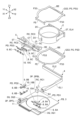
- FIG. 1 is an exploded perspective view of a camera module including an optical element driving device
- FIG. 2 is an exploded perspective view of the optical element driving device.
- FIG. 2 is an exploded perspective view of the optical element driving device.
- FIG. 2 is an exploded perspective view of the optical element driving device.
- FIG. 11A and 11B are diagrams illustrating the movement of a piezoelectric driving unit.
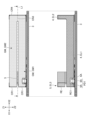
- 4 is a front view of the optical element driving device with a cover member removed.
- FIG. 11 is a right side view of the optical element driving device with the cover member removed.
- FIG. 4 is a left side view of the optical element driving device with a cover member removed.
- FIG. 13 is a rear view of the optical element driving device with a cover member removed.
- FIG. 4 is a top view of the optical element driving device with a cover member removed.
- FIG. 11A and 11B are diagrams illustrating the movement of an optical element holding member.
- FIG. 13 is an exploded perspective view of another configuration example of the optical element driving device.
- 14 is an exploded perspective view of components constituting the optical element driving device shown in FIG. 13.
- FIG. 1 is an exploded perspective view of a camera module CM including the optical element driving device 101.
- Figs. 2 to 4 are exploded perspective views of the optical element driving device 101.
- X1 represents one direction of the X-axis constituting the three-dimensional orthogonal coordinate system
- X2 represents the other direction of the X-axis
- Y1 represents one direction of the Y-axis constituting the three-dimensional orthogonal coordinate system
- Y2 represents the other direction of the Y-axis
- Z1 represents one direction of the Z-axis constituting the three-dimensional orthogonal coordinate system
- Z2 represents the other direction of the Z-axis.
- the X1 side of the optical element driving device 101 corresponds to the front side (front side) of the optical element driving device 101
- the X2 side of the optical element driving device 101 corresponds to the rear side (rear side) of the optical element driving device 101.
- the Y1 side of the optical element driving device 101 corresponds to the left side of the optical element driving device 101, and the Y2 side of the optical element driving device 101 corresponds to the right side of the optical element driving device 101.
- the Z1 side of the optical element driving device 101 corresponds to the upper side (subject side) of the optical element driving device 101, and the Z2 side of the optical element driving device 101 corresponds to the lower side (imaging element side) of the optical element driving device 101. This is the same in the other figures.
- the camera module CM is composed of an optical element driving device 101, a lens body LS which is an example of an optical element OE, and an image sensor IS mounted on a substrate (not shown) so as to face the lens body LS.
- the optical element driving device 101 has a roughly rectangular parallelepiped shape and is attached to the substrate on which the image sensor IS is mounted.
- the optical element OE may be a mirror, a prism, a diffraction grating, a light emitting element, a light receiving element, an image sensor, an optical filter, or the like.
- the optical element OE may also be a combination of multiple types of elements. If the optical element OE is an element other than the lens body LS, the image sensor IS may be omitted.
- the optical element driving device 101 includes a fixed side member FB and a movable side member MB as shown in FIG. 2.
- the fixed side member FB includes a cover member 1 and a base member 3
- the movable side member MB includes an optical element holding member 2, a first movable body 4, and a second movable body 5.
- the fixed side member FB and the movable side member MB are connected by a guide mechanism GM.
- the movable side member MB is supported so as to be guided in a predetermined moving direction by the guide mechanism GM.
- the predetermined moving direction includes a first moving direction (X-axis direction) perpendicular to the optical axis direction, a second moving direction (Y-axis direction) perpendicular to each of the optical axis direction and the first moving direction, and a third moving direction (Z-axis direction) parallel to the optical axis direction.
- the optical axis direction includes the direction of the optical axis OA of the lens body LS held by the optical element holding member 2, and a direction parallel to the optical axis OA.
- the lens body LS is, for example, a cylindrical lens barrel equipped with at least one lens.
- the movable member MB is configured to be moved in a predetermined direction by a force generated by a piezoelectric driving unit PD, which is an example of a driving unit.
- the cover member 1 is a member that constitutes a part of the housing HS, and is configured to cover the upper and side parts of the movable side member MB.
- the cover member 1 has an outer peripheral wall portion 1A of a substantially rectangular tube shape that defines the storage section 1S, and a flat rectangular annular top plate portion 1B, as shown in FIG. 2.
- the outer peripheral wall portion 1A includes a first side plate portion 1A1 to a fourth side plate portion 1A4.
- the first side plate portion 1A1 and the third side plate portion 1A3 face each other, and the second side plate portion 1A2 and the fourth side plate portion 1A4 face each other.
- the second side plate portion 1A2 and the fourth side plate portion 1A4 extend perpendicular to the first side plate portion 1A1 and the third side plate portion 1A3.
- the first side plate portion 1A1 and the third side plate portion 1A3 extend perpendicular to the second side plate portion 1A2 and the fourth side plate portion 1A4.
- a circular opening 1K is formed in the center of the top plate 1B.
- the cover member 1 is made by punching and drawing a metal plate. However, the cover member 1 may be made of other materials such as synthetic resin.
- the base member 3 is a member that constitutes a part of the housing HS.
- the base member 3 is made of synthetic resin.
- the base member 3 may be made of metal.
- the base member 3 has a flat rectangular ring-shaped base 3B. At two of the four corners of the base 3B, protrusions 3P that protrude upward are formed.
- a circular opening 3K is formed in the center of the base 3B.
- the protrusions 3P include a left rear protrusion 3PBL and a left front protrusion 3PFL.
- a recess 3Q that accommodates the biasing member 6 is formed on the upper surface of the base 3B.
- the base 3B is formed with a first recess 3Q1 that accommodates the first biasing member 6A and a second recess 3Q2 that accommodates the second biasing member 6B.
- the base member 3 is joined to the cover member 1 by adhesive or the like to constitute the housing HS together with the cover member 1.
- the optical element holding member 2 is configured to hold the optical element OE.
- the optical element holding member 2 is produced by injection molding a synthetic resin such as liquid crystal polymer (LCP).
- the optical element holding member 2 is configured to hold the lens body LS by fixing the lens body LS to the inside of the cylindrical through-hole 2C with an adhesive.
- the optical element holding member 2 also has a protrusion 2T that protrudes radially (rearward) from the outer circumferential surface of the tubular portion in which the through-hole 2C is formed.
- the protrusion 2T constitutes a fourth extension EL4 to which the guide mechanism GM (leaf spring member PS) is fixed.
- the first movable body 4 is a member configured to be driven by the piezoelectric drive unit PD (first piezoelectric drive unit PD1) and guided by the guide mechanism GM (first guide mechanism GM1) so as to be able to move in a first movement direction (X-axis direction).
- the first movable body 4 is a member formed to be approximately L-shaped in a plan view along the up-down direction, and has a first extension portion EL1 extending in the first movement direction (X-axis direction) and a second extension portion EL2 extending in the second movement direction (Y-axis direction).
- the first movable body 4 is formed from synthetic resin.
- the second movable body 5 is a member configured to be driven by the piezoelectric drive unit PD (second piezoelectric drive unit PD2) and guided by the guide mechanism GM (second guide mechanism GM2) to move in the second movement direction (Y-axis direction).
- the second movable body 5 is a member formed to have a substantially rectangular parallelepiped shape, and has a third extension portion EL3 extending in the second movement direction (Y-axis direction).
- the second movable body 5 is also formed of synthetic resin.
- the third extension portion EL3 is arranged to face the second extension portion EL2 of the first movable body 4 across the optical element holding member 2 in the first movement direction (X-axis direction).
- the central portion CT of the third extension portion EL3 in the second movement direction (Y-axis direction) has its front end surface (end surface on the X1 side) located rearward (X2 side) from the front end surface of the left side (Y1 side) and the front end surface of the right side (Y2 side) of the central portion CT. Furthermore, in the central portion CT, a through hole 5C that is rectangular in front view and penetrates in the X-axis direction is formed so that a piezoelectric driving unit PD (third piezoelectric driving unit PD3) for driving the optical element holding member 2 can be disposed. In addition, in the central portion CT, concave mounting portions 5T are provided on both the left side (Y1 side) and the right side (Y2 side) of the through hole 5C. The mounting portions 5T are used to fix the third biasing member 6C.
- the receiving member RC is a member that receives the driving force generated by the piezoelectric driving unit PD.
- the receiving member RC is a cylindrical member that is formed of a metal such as titanium copper or stainless steel and extends along the moving direction.
- the receiving member RC may be formed of other metals.
- the other metals may be either magnetic metals or non-magnetic metals.
- the receiving member RC includes a first receiving member RC1, a second receiving member RC2, and a third receiving member RC3, as shown in FIG. 4.
- the first receiving member RC1 is fitted into a U-shaped groove 4U formed at the front end of the first movable body 4 and fixed with adhesive, and is arranged so that it can move in the X-axis direction together with the first movable body 4.
- the second receiving member RC2 is fitted into a U-shaped groove 5U (see the upper diagram in FIG. 9) formed at the left end of the second movable body 5 and fixed with adhesive, and is arranged so that it can move in the Y-axis direction together with the second movable body 5.
- the third receiving member RC3 is fitted into a U-shaped groove 2U formed on the front side of the outer circumferential surface of the cylindrical portion in which the through portion 2C of the optical element holding member 2 is formed, and is fixed with adhesive so that it can move in the Z-axis direction together with the optical element holding member 2.
- the leaf spring member PS is configured to support the optical element holding member 2 so that it can move up and down.
- the leaf spring member PS includes an upper leaf spring member PSU and a lower leaf spring member PSD having the same structure as shown in FIG. 4.
- Each of the upper leaf spring member PSU and the lower leaf spring member PSD has a substantially rectangular annular outer shape when viewed from above, and one end (front connecting part FE) extending along the Y-axis direction is fixed to the second movable body 5 (third extension part EL3) by adhesive, and the other end (rear connecting part BE) also extending along the Y-axis direction is fixed to the protrusion 2T (fourth extension part EL4) of the optical element holding member 2 by adhesive.
- the biasing member 6 is configured to bias the piezoelectric driving unit PD toward the receiving member RC.
- the biasing member 6 is configured as a leaf spring member formed by pressing a metal plate made of titanium copper.
- the metal plate may be formed of other metals such as stainless steel.
- the biasing member 6 includes a first biasing member 6A, a second biasing member 6B, and a third biasing member 6C.
- both ends of the first biasing member 6A are fixed to the upper surface of the base 3B of the base member 3 by adhesive, and the remaining portion is housed in the first recess 3Q1 so as not to contact the bottom of the first recess 3Q1.
- the first biasing member 6A is configured to press the first piezoelectric driving unit PD1 toward the first receiving member RC1 fixed to the first movable body 4.
- one end of the second biasing member 6B is fixed to the upper surface of the base portion 3B of the base member 3 by adhesive, the other end is fixed to the upper end surface of the left front protrusion portion 3PFL of the base member 3 by adhesive, and the remaining portion is accommodated in the second recess 3Q2 so as not to contact the bottom of the second recess 3Q2.
- the second biasing member 6B is configured to be able to press the second piezoelectric driving portion PD2 toward the second receiving member RC2 fixed to the second movable body 5. Also, as shown in FIG.
- both ends of the third biasing member 6C are fixed to the mounting portion 5T of the second movable body 5 by adhesive.
- the front surfaces (X1 side surfaces) of both ends of the third biasing member 6C are covered by the front connecting portion FE of the leaf spring member PS fixed to the center portion CT of the third extension portion EL3. That is, both ends of the third biasing member 6C are clamped between the mounting portion 5T of the second movable body 5 and the front connecting portion FE of the leaf spring member PS.
- the remaining portion of the third biasing member 6C is housed in the space between the upper leaf spring member PSU and the lower leaf spring member PSD so as not to come into contact with the leaf spring member PS. In this way, the third biasing member 6C is configured to be able to press the third piezoelectric drive unit PD3 towards the third receiving member RC3 fixed to the optical element holding member 2.
- Figure 5 is an exploded perspective view of the piezoelectric drive unit PD supported by the biasing member 6.
- the piezoelectric drive unit PD is configured to be able to move the movable side member MB along a predetermined movement direction.
- the piezoelectric drive unit PD is an example of a friction drive unit that utilizes the drive system disclosed in U.S. Patent No. 7,786,648, and includes a piezoelectric element 8, a contact member 9, and a flexible wiring board 10.
- the piezoelectric drive unit PD is configured to be biased by a biasing member 6 and pressed against a receiving member RC (see FIG. 4). In other words, the contact member 9 of the piezoelectric drive unit PD and the receiving member RC are in contact with each other so as to be pressed against each other by the biasing member 6.
- the piezoelectric drive unit PD includes a first piezoelectric drive unit PD1 that moves the first movable body 4 in a first movement direction (X-axis direction), a second piezoelectric drive unit PD2 that moves the second movable body 5 in a second movement direction (Y-axis direction), and a third piezoelectric drive unit PD3 that moves the optical element holding member 2 in a third movement direction (Z-axis direction).
- the first piezoelectric driving unit PD1 includes a first piezoelectric element 8A, a first contact member 9A, and a first flexible wiring board 10A, and is configured to be biased by a first biasing member 6A and pressed against a first receiving member RC1 (see Figure 4) fixed to the first movable body 4.
- the second piezoelectric driving unit PD2 includes a second piezoelectric element 8B, a second contact member 9B, and a second flexible wiring board 10B, and is configured to be biased by a second biasing member 6B and pressed against a second receiving member RC2 (see FIG. 4) fixed to the second movable body 5.
- the third piezoelectric driving unit PD3 includes a third piezoelectric element 8C, a third contact member 9C, and a third flexible wiring board 10C, and is configured to be biased by a third biasing member 6C and pressed against a third receiving member RC3 (see FIG. 4) fixed to the optical element holding member 2.
- each of the first piezoelectric element 8A, the second piezoelectric element 8B, and the third piezoelectric element 8C is configured to realize bending vibration in response to an applied voltage.
- the first piezoelectric element 8A extends in the Y-axis direction along the first rotation axis 8AX
- the second piezoelectric element 8B extends in the X-axis direction along the second rotation axis 8BX
- the third piezoelectric element 8C extends in the Y-axis direction along the third rotation axis 8CX.
- each of the first piezoelectric element 8A, the second piezoelectric element 8B, and the third piezoelectric element 8C is configured to realize bending vibration having two nodes (nodes ND). When bending vibration is performed, the two nodes ND hardly vibrate.
- a cross pattern is attached to the position of the node ND in each of the first piezoelectric element 8A, the second piezoelectric element 8B, and the third piezoelectric element 8C.
- the position of the node ND in the piezoelectric element 8 includes the position of the first node ND1 and the position of the second node ND2.
- the position of the node ND corresponds to a position that is a predetermined distance from the end of the piezoelectric element 8. The predetermined distance is, for example, approximately one-quarter of the total length of the piezoelectric element 8.
- the first flexible wiring board 10A is a flexible wiring board including a conductive pattern, and is configured to electrically connect an external voltage supply source (control circuit) and the first piezoelectric element 8A.
- the first flexible wiring board 10A is configured to apply a voltage to the first piezoelectric element 8A.
- the first flexible wiring board 10A includes a joint 10AJ that is joined to the first piezoelectric element 8A, and an extension 10AE that extends from the joint 10AJ in the Y1 direction.
- the first piezoelectric element 8A also extends along the first rotation axis 8AX and is joined to the upper (Z1 side) surface of the first flexible wiring board 10A by adhesive AD.
- the first piezoelectric element 8A has electrodes ED at each of the four corners of the lower (Z2 side) surface.
- the four electrodes ED of the first piezoelectric element 8A are joined to four connection parts PT formed on the upper surface of the first flexible wiring board 10A via adhesive AD.
- the second flexible wiring board 10B is a flexible wiring board including a conductive pattern, and is configured to electrically connect an external voltage supply source (control circuit) and the second piezoelectric element 8B.
- the second flexible wiring board 10B is configured to apply a voltage to the second piezoelectric element 8B.
- the second flexible wiring board 10B includes a joint 10BJ that is joined to the second piezoelectric element 8B, and an extension 10BE that extends from the joint 10BJ in the Y2 direction.
- the second piezoelectric element 8B extends along the second rotation axis 8BX, and is joined to the upper (Z1) surface of the second flexible wiring board 10B by adhesive AD.
- the second piezoelectric element 8B has electrodes ED at each of the four corners of the lower (Z2) surface.
- the four electrodes ED of the second piezoelectric element 8B are then bonded to the four connection parts PT formed on the upper surface of the second flexible wiring board 10B via adhesive AD.
- the third flexible wiring board 10C is a flexible wiring board including a conductive pattern, and is configured to electrically connect an external voltage supply source (control circuit) and the third piezoelectric element 8C.
- the third flexible wiring board 10C is configured to apply a voltage to the third piezoelectric element 8C.
- the third flexible wiring board 10C includes a joint 10CJ that is joined to the third piezoelectric element 8C, and an extension 10CE that extends in the Z2 direction from the joint 10CJ.
- the third piezoelectric element 8C extends along the third rotation axis 8CX, and is joined to the rear (X2) surface of the third flexible wiring board 10C by an adhesive AD.
- the third piezoelectric element 8C has electrodes ED at each of the four corners of the front (X1) surface.
- the four electrodes ED of the third piezoelectric element 8C are then bonded to the four connection parts PT formed on the rear surface of the third flexible wiring board 10C via adhesive AD.
- the adhesive AD is an anisotropic conductive film, which is heated and pressurized while placed between the piezoelectric element 8 and the flexible wiring board 10, and is fixed to both the piezoelectric element 8 and the flexible wiring board 10. This electrically connects the four electrodes ED of the piezoelectric element 8 to the four connection points PT that are part of the conductive pattern of the flexible wiring board 10 individually.
- the adhesive AD may be a conductive adhesive or solder, etc. Note that, although the anisotropic conductive film as the adhesive AD is separated into two parts in the illustrated example, it may also be integrated into one part that is approximately the same size as the piezoelectric element 8.
- conductive patterns are formed on both sides of the flexible wiring board 10, and insulating films are provided on both sides to cover the conductive patterns except for the connection parts PT and the connection parts with the common flexible wiring board 11.
- An insulating protective film is provided on the parts that come into contact with the piezoelectric elements 8 and the parts that come into contact with the biasing members 6 to ensure more reliable insulation.
- the common flexible wiring board 11 is a flexible wiring board including a conductive pattern, and is configured to electrically connect an external voltage supply source (control circuit) and the flexible wiring board 10.
- the common flexible wiring board 11 is configured so that the connection portions of the first flexible wiring board 10A, the second flexible wiring board 10B, and the third flexible wiring board 10C are connected to a predetermined connection area by a conductive adhesive or solder, etc.
- a dot pattern is applied to the connection area ZN, which is the predetermined connection area to which the second flexible wiring board 10B is connected.
- the first flexible wiring board 10A and the third flexible wiring board 10C are already connected to the common flexible wiring board 11.
- the common flexible wiring board 11 has 13 terminal portions TM.
- the 13 terminals TM include four terminals TM corresponding to the four connection parts PT formed on the first flexible wiring board 10A, four terminals TM corresponding to the four connection parts PT formed on the second flexible wiring board 10B, four terminals TM corresponding to the four connection parts PT formed on the third flexible wiring board 10C, and one terminal TM corresponding to the ground potential.
- the common flexible wiring board 11 may be a rigid wiring board.
- the first piezoelectric driving unit PD1 is configured to be biased upward by a first biasing member 6A fixed to the base member 3 and pressed against the first receiving member RC1.
- the first biasing member 6A is configured to contact the lower (Z2 side) surface of the first flexible wiring board 10A at positions (the position of the first convex portion SP1 and the position of the second convex portion SP2) corresponding to each of the two nodes ND formed during bending vibration of the first piezoelectric element 8A.
- the first biasing member 6A and the first flexible wiring board 10A are joined by, for example, an adhesive.
- the second piezoelectric driving unit PD2 is configured to be biased upward by a second biasing member 6B fixed to the base member 3 and pressed against the second receiving member RC2.
- the second biasing member 6B is configured to contact the lower (Z2 side) surface of the second flexible wiring board 10B at positions (the position of the first convex portion SP1 and the position of the second convex portion SP2) corresponding to each of the two nodes ND formed during bending vibration of the second piezoelectric element 8B.
- the second biasing member 6B and the second flexible wiring board 10B are joined together by, for example, an adhesive.
- the third piezoelectric driving unit PD3 is configured to be biased rearward by a third biasing member 6C fixed to the second movable body 5 and pressed against the third receiving member RC3.
- the third biasing member 6C is configured to contact the front (X1 side) surface of the third flexible wiring board 10C at positions (the position of the first convex portion SP1 and the position of the second convex portion SP2) corresponding to each of the two nodes ND formed during bending vibration of the third piezoelectric element 8C.
- the third biasing member 6C and the third flexible wiring board 10C are joined together by, for example, an adhesive.
- the biasing member 6 is composed of a leaf spring member formed from a single metal plate.
- the first biasing member 6A has a fixed portion 6AF fixed to the base member 3, a support portion 6AS supporting the first piezoelectric driving unit PD1, and an elastically deformable elastic deformation portion 6AE provided between the fixed portion 6AF and the support portion 6AS.
- the second biasing member 6B has a fixed portion 6BF fixed to the base member 3, a support portion 6BS supporting the second piezoelectric driving unit PD2, and an elastically deformable elastic deformation portion 6BE provided between the fixed portion 6BF and the support portion 6BS.
- the third biasing member 6C has a fixed portion 6CF fixed to the second movable body 5, a support portion 6CS supporting the third piezoelectric driving unit PD3, and an elastically deformable elastic deformation portion 6CE provided between the fixed portion 6CF and the support portion 6CS.
- the fixed portion 6AF includes a first fixed portion 6AF1 and a second fixed portion 6AF2
- the elastic deformation portion 6AE includes a first elastic deformation portion 6AE1 provided between the first fixed portion 6AF1 and the support portion 6AS, and a second elastic deformation portion 6AE2 provided between the second fixed portion 6AF2 and the support portion 6AS.
- the fixed portion 6BF includes a first fixed portion 6BF1 and a second fixed portion 6BF2
- the elastic deformation portion 6BE includes a first elastic deformation portion 6BE1 provided between the first fixed portion 6BF1 and the support portion 6BS, and a second elastic deformation portion 6BE2 provided between the second fixed portion 6BF2 and the support portion 6BS.
- the fixed portion 6CF includes a first fixed portion 6CF1 and a second fixed portion 6CF2
- the elastic deformation portion 6CE includes a first elastic deformation portion 6CE1 provided between the first fixed portion 6CF1 and the support portion 6CS, and a second elastic deformation portion 6CE2 provided between the second fixed portion 6CF2 and the support portion 6CS.
- Each of the support portion 6AS and the support portion 6BS includes a first convex portion SP1 and a second convex portion SP2 that protrude upward (in the Z1 direction), and the support portion 6CS includes a first convex portion SP1 and a second convex portion SP2 that protrude backward (in the X2 direction).
- the first convex portion SP1 and the second convex portion SP2 are drawn beads formed by drawing.
- the first convex portion SP1 and the second convex portion SP2 may be formed by doweling or half-punching.
- each of the first convex portion SP1 and the second convex portion SP2 is formed so as to extend perpendicular to the extension direction of the piezoelectric element 8.
- the positions at which the first convex portion SP1 and the second convex portion SP2 are arranged are preferably positions corresponding to the nodes ND of the piezoelectric element 8, and more specifically, are spaced apart from each other in the extension direction of the piezoelectric element 8.
- the first piezoelectric driving unit PD1 is attached to the first biasing member 6A so that the lower surface (Z2 side surface) of the joint 10AJ of the first flexible wiring board 10A is fixed to the support 6AS by adhesive. Specifically, the first piezoelectric driving unit PD1 is attached to the first biasing member 6A so that the positions corresponding to the first node ND1 and second node ND2 of the first piezoelectric element 8A at the joint 10AJ and the first convex portion SP1 and second convex portion SP2 at the support 6AS are fixed by adhesive.
- the first piezoelectric driving unit PD1 is attached to the first biasing member 6A so that the portions of the lower surface (Z2 side surface) of the joint 10AJ that do not correspond to the first node ND1 and second node ND2 of the first piezoelectric element 8A do not come into contact with the support 6AS of the first biasing member 6A.
- the second piezoelectric driving unit PD2 is attached to the second biasing member 6B so that the lower surface (Z2 side surface) of the joint 10BJ of the second flexible wiring board 10B is fixed to the support 6BS by adhesive. Specifically, the second piezoelectric driving unit PD2 is attached to the second biasing member 6B so that the positions corresponding to the first node ND1 and the second node ND2 of the second piezoelectric element 8B at the joint 10BJ and the first convex portion SP1 and the second convex portion SP2 at the support 6BS are fixed by adhesive.
- the second piezoelectric driving unit PD2 is attached to the second biasing member 6B so that the portions of the lower surface (Z2 side surface) of the joint 10BJ that do not correspond to the first node ND1 and the second node ND2 of the second piezoelectric element 8B do not come into contact with the support 6BS of the second biasing member 6B.
- the third piezoelectric driving unit PD3 is attached to the third biasing member 6C so that the front surface (X1 side surface) of the joint 10CJ of the third flexible wiring board 10C is fixed to the support 6CS by adhesive.
- the third piezoelectric driving unit PD3 is attached to the third biasing member 6C so that the positions corresponding to the first node ND1 and the second node ND2 of the third piezoelectric element 8C at the joint 10CJ and the first convex portion SP1 and the second convex portion SP2 at the support 6CS are fixed by adhesive.
- the third piezoelectric driving unit PD3 is attached to the third biasing member 6C so that the portions of the front surface (X1 side surface) of the joint 10CJ that do not correspond to the first node ND1 and the second node ND2 of the third piezoelectric element 8C do not come into contact with the support 6CS of the third biasing member 6C.
- FIG. 6 is a diagram showing the first piezoelectric element 8A and the first contact member 9A constituting the first piezoelectric driving unit PD1.
- the first flexible wiring board 10A is omitted from the illustration for clarity.
- the topmost diagram in FIG. 6 is a perspective view of the first piezoelectric element 8A and the first contact member 9A
- the second, third, and fourth diagrams from the top in FIG. 6 are front views of the first piezoelectric element 8A and the first contact member 9A
- the fifth, sixth, and seventh diagrams from the top in FIG. 6 are bottom views of the first piezoelectric element 8A and the first contact member 9A.
- the bent shape of the first piezoelectric driving unit PD1 is exaggerated for ease of understanding.
- the following description with reference to FIG. 6 relates to the movement of the first piezoelectric driving unit PD1, but is similarly applicable to the movements of the second piezoelectric driving unit PD2 and the third piezoelectric driving unit PD3. This is because the first piezoelectric drive unit PD1, the second piezoelectric drive unit PD2, and the third piezoelectric drive unit PD3 each have the same configuration.
- the first piezoelectric element 8A has two parts (first part 8A1 and second part 8A2) aligned in the first movement direction (X-axis direction), and two electrodes ED to which a voltage can be applied are formed on each of the two parts.
- the first electrode ED1 and the second electrode ED2 are formed on the first part 8A1
- the first electrode ED11 and the second electrode ED12 are formed on the second part 8A2. Note that in FIG. 6, for clarity, a dot pattern is applied to the first part 8A1, and a diagonal line pattern is applied to the second part 8A2.
- the first piezoelectric driving unit PD1 can, for example, cause the first piezoelectric element 8A to undergo bending vibration (circular motion) so that the trajectory of the center point CP, which is a predetermined point of the first piezoelectric element 8A (first piezoelectric driving unit PD1), becomes a circular orbit centered on the first rotation axis 8AX.
- the first piezoelectric element 8A can achieve a movement (circular motion) in which the center point CP describes a circle.
- the center point CP of the first piezoelectric element 8A is the center of gravity of the first piezoelectric element 8A, and the first rotation axis 8AX is parallel to the Y axis.
- the center point CP of the circular motion may be located within the first contact member 9A fixed to the first piezoelectric element 8A. This is because the first contact member 9A also performs a circular motion together with the first piezoelectric element 8A.
- the first piezoelectric drive unit PD1 can switch the movement direction (rotation direction) of the center point CP that follows the circular orbit between clockwise and counterclockwise as viewed from the Y1 side by applying a voltage to the first portion 8A1 and the second portion 8A2 at an appropriate timing.
- the first piezoelectric drive unit PD1 can switch the movement direction of the first receiving member RC1 (and the first movable body 4 (movable side member MB) to which the first receiving member RC1 is fixed) along the first movement direction (X-axis direction).
- the circle (circular orbit) described by the center point CP does not have to be a perfect circle (true circle), but may be approximately circular.
- the dashed arrows drawn around the first piezoelectric element 8A in the top diagram of FIG. 6 show an example of bending vibration of the first piezoelectric element 8A (circular motion in which the first piezoelectric element 8A rotates clockwise around the first rotation axis 8AX as viewed from the Y1 side while bending).
- the movable side member MB including the first support member RC1 in contact with the first contact member 9A of the first piezoelectric drive unit PD1 moves forward (X1 direction).
- the first piezoelectric element 8A can also rotate counterclockwise around the first rotation axis 8AX as viewed from the Y1 side while bending.
- the movable side member MB including the first support member RC1 in contact with the first contact member 9A of the first piezoelectric drive unit PD1 moves backward (X2 direction).
- the first movable body 4 to which the first receiving member RC1 is attached is moved forward (X1 direction) when the rotation direction of the center point CP of the first piezoelectric element 8A is clockwise when viewed from the left side, and is moved backward (X2 direction) when the rotation direction of the center point CP of the first piezoelectric element 8A is counterclockwise.
- the first contact member 9A is attached to the first piezoelectric element 8A and is configured to contact the first receiving member RC1.
- the first contact member 9A is bonded to the upper surface of the first piezoelectric element 8A with an adhesive so as to cover the entire upper (Z1 side) surface of the first piezoelectric element 8A.
- the first contact member 9A is formed of a metal such as titanium copper or stainless steel, and is configured with an appropriate thickness so that it can perform bending vibration (circular motion) together with the bending vibration (circular motion) of the first piezoelectric element 8A.
- the first contact member 9A is a friction plate made of stainless steel.
- the first contact member 9A extends to the same length as the first piezoelectric element 8A in the same direction (Y-axis direction) as the extension direction of the first piezoelectric element 8A.
- the first contact member 9A is configured to contact the first receiving member RC1 at the center in the extension direction.
- the first contact member 9A is configured to come into contact with the first receiving member RC1 at a portion where the amplitude of the bending vibration (circular motion) is maximum (a portion corresponding to the antinode of the bending vibration).
- the first contact member 9A has a surface 9AS on the side (Z1 side) that comes into contact with the first receiving member RC1, which is a convex curved surface that is convex toward the Z1 side.
- the surface 9AS is configured to form a surface with one convex portion.
- the reason for contacting the first metallic support member RC1 with the first metallic contact member 9A is to prevent wear of the movable side member MB (first movable body 4) due to contact between the synthetic resin movable side member MB (first movable body 4) and the metallic first contact member 9A. Note that, as long as contact between the first support member RC1 and the first contact member 9A can be obtained, the length dimension of the first contact member 9A in the Y-axis direction does not have to be the same as the length dimension of the first piezoelectric element 8A in the Y-axis direction.
- the length dimension of the first contact member 9A in the Y-axis direction may be smaller than the length dimension of the first piezoelectric element 8A in the Y-axis direction.
- the length of the first contact member 9A in the extension direction (Y-axis direction) is equal to or greater than the length of the first piezoelectric element 8A.
- the first piezoelectric element 8A and the first contact member 9A each bend so as to become convex upward (toward the Z1 side).
- the state of the first piezoelectric drive unit PD1 when the first piezoelectric element 8A and the first contact member 9A each become convex upward is also referred to as the "upper convex state”.
- the first piezoelectric element 8A and the first contact member 9A each extend linearly, as shown in the third figure from the top and the sixth figure from the top.
- the state of the first piezoelectric drive unit PD1 when the first piezoelectric element 8A and the first contact member 9A each extend linearly is also referred to as the “neutral state”. Also, the state when the application of voltage is stopped is also referred to as the "initial state”.
- the first piezoelectric element 8A and the first contact member 9A each bend so as to become convex downward (toward the Z2 side).
- the state of the first piezoelectric drive unit PD1 when the first piezoelectric element 8A and the first contact member 9A each become convex downward is also referred to as the "lower convex state”.
- the first piezoelectric element 8A and the first contact member 9A each bend so as to become convex toward the front (X1 side).
- the state of the first piezoelectric drive unit PD1 when the first piezoelectric element 8A and the first contact member 9A each become convex toward the front is also referred to as the "front convex state”.
- the first piezoelectric element 8A and the first contact member 9A each bend so as to become convex toward the rear (X2 side).
- the state of the first piezoelectric drive unit PD1 when the first piezoelectric element 8A and the first contact member 9A each become convex toward the rear is also referred to as the "rear convex state”.
- the first contact member 9A fixed to one surface of the first piezoelectric element 8A does not change its dimension in the extension direction. Therefore, the first piezoelectric drive unit PD1 deforms to the state described above.
- the first flexible wiring board 10A fixed to the other surface of the first piezoelectric element 8A can deform in accordance with the change in shape of the first piezoelectric element 8A.
- the first piezoelectric drive unit PD1 can achieve circular motion that rotates clockwise as viewed from the Y1 side by repeatedly changing its state in the order of upper convex state, front convex state, lower convex state, rear convex state, upper convex state, etc.
- the first piezoelectric drive unit PD1 can achieve circular motion that rotates counterclockwise as viewed from the Y1 side by repeatedly changing its state in the order of upper convex state, rear convex state, lower convex state, front convex state, upper convex state, etc.
- the first piezoelectric drive unit PD1 can achieve up-down motion by repeatedly changing its state in the order of upper convex state, lower convex state, upper convex state, etc., and can achieve forward-backward motion by repeatedly changing its state in the order of front convex state, rear convex state, front convex state, etc.
- the first piezoelectric drive unit PD1 is configured so that the first electrode ED1 is connected to a high potential and the second electrode ED2 is connected to a low potential so that the first portion 8A1 contracts, and so that the first electrode ED1 is connected to a low potential and the second electrode ED2 is connected to a high potential so that the first portion 8A1 expands; however, it may also be configured so that the first electrode ED1 is connected to a low potential and the second electrode ED2 is connected to a high potential so that the first portion 8A1 contracts, and so that the first electrode ED1 is connected to a high potential and the second electrode ED2 is connected to a low potential so that the first portion 8A1 expands. The same applies to the second portion 8A2.
- the second piezoelectric element 8B of the second piezoelectric drive unit PD2 is arranged to extend in the X-axis direction. Therefore, with respect to the second piezoelectric drive unit PD2, the "front convex state" of the first piezoelectric drive unit PD1 described above corresponds to the "left convex state" of the second piezoelectric drive unit PD2 when the second piezoelectric element 8B and the second contact member 9B are each convex to the left, and the "rear convex state" of the first piezoelectric drive unit PD1 described above corresponds to the "right convex state" of the second piezoelectric drive unit PD2 when the second piezoelectric element 8B and the second contact member 9B are each convex to the right.
- the second piezoelectric drive unit PD2 can achieve up-down movement by repeatedly changing its state in the order of upper convex state, lower convex state, upper convex state, etc., and can achieve left-right movement by repeatedly changing its state in the order of left convex state, right convex state, left convex state, etc.
- the guide mechanism GM is configured to guide the movable member MB, which moves relative to the fixed member FB, along a predetermined movement direction.
- the guide mechanism GM includes a first guide mechanism GM1, a second guide mechanism GM2, and a third guide mechanism GM3.
- the first guide mechanism GM1 is configured to guide the movement of the first movable body 4 in the first movement direction (X-axis direction).
- the second guide mechanism GM2 is configured to guide the movement of the second movable body 5 in the second movement direction (Y-axis direction).
- the third guide mechanism GM3 is configured to guide the movement of the optical element holding member 2 in the third movement direction (Z-axis direction).
- Figure 7 is a front view of the optical element driving device 101 with the cover member 1 removed.
- Figure 8 is a right side view of the optical element driving device 101 with the cover member 1 removed.
- Figure 9 is a left side view of the optical element driving device 101 with the cover member 1 removed.
- Figure 10 is a rear view of the optical element driving device 101 with the cover member 1 removed.
- Figure 11 is a top view of the optical element driving device 101 with the cover member 1 removed.
- Figure 12 is a diagram of the optical element holding member 2, the third biasing member 6C, the third piezoelectric driving unit PD3, and the third guide mechanism GM3.
- each of Fig. 7 to Fig. 11 are views of the optical element driving device 101 with the cover member 1 removed
- the lower views of each of Fig. 7 to Fig. 10 are views of the optical element driving device 101 with the first guide mechanism GM1 and the second guide mechanism GM2 further removed.
- the lower view of Fig. 11 is a view showing a cross section of the optical element driving device 101 when viewed from above on a virtual plane parallel to the XY plane including the cutting line L1 shown by the dashed line in each of the upper views of Fig. 7 to Fig. 10.
- FIG. 12 is a right side view of the optical element holding member 2, the third biasing member 6C, the third piezoelectric driving unit PD3, and the third guide mechanism GM3, and the lower view of Fig. 12 is a bottom view of the optical element holding member 2, the third biasing member 6C, the third piezoelectric driving unit PD3, and the third guide mechanism GM3.
- a fine dot pattern is applied to the optical element holding member 2
- a coarse dot pattern is applied to the second movable body 5
- an even coarser dot pattern is applied to the guide mechanism GM.
- the first guide mechanism GM1 is formed of a metal plate as the first guide spring member GS1, and has a first connecting portion CN1 and a pair of first flat spring portions FS1.
- the first guide mechanism GM1 has a pair of first flat spring portions FS1 that face each other in a parallel state with a space between them in the first moving direction (X-axis direction) and extend in the second moving direction (Y-axis direction).
- the plate surfaces of the pair of first flat spring portions FS1 are perpendicular to the first moving direction (X-axis direction).
- One end portion FS1F of each of the pair of first flat spring portions FS1 in the second moving direction (Y-axis direction) is fixed to the fixed side member FB (the protruding portion 3P of the base member 3) by adhesive, and the other end portion FS1S of each of the pair of first flat spring portions FS1 in the second moving direction (Y-axis direction) is fixed to the first movable body 4 by adhesive.
- the first connecting portion CN1 is configured to connect the other ends FS1S of the pair of first flat spring portions FS1.
- the first connecting portion CN1 has a first flat portion FP1 extending in the first moving direction (X-axis direction) and a plate surface perpendicular to the second moving direction (Y-axis direction), and a first bent portion FD1 bent inwardly and substantially perpendicularly from the lower end of the first flat portion FP1.
- the "inner side” means the side closer to the optical element OE, that is, the side opposite to the outer side, which is the side farther from the optical element OE.
- the first movable body 4 has a first extending portion EL1 having a substantially rectangular parallelepiped shape extending in the first moving direction (X-axis direction) and a second extending portion EL2 having a substantially rectangular parallelepiped shape extending in the second moving direction (Y-axis direction).
- the inner surface (rear surface) of the other end FS1S of the first front flat spring portion FS1, the inner surface (front surface) of the other end FS1S of the first rear flat spring portion FS1, the inner surface (left surface) of the first flat portion FP1 of the first connecting portion CN1, and the upper surface of the first folded portion FD1 of the first connecting portion CN1 are fixed to the front surface, rear surface, right surface, and lower surface of the first extending portion EL1 by adhesive, respectively.
- the first piezoelectric driving unit PD1 realizes a circular motion rotating clockwise as viewed from the Y1 side by repeatedly changing its state in the order of upper convex state, front convex state, lower convex state, rear convex state, upper convex state, etc., and can move the first movable body 4 forward (X1 direction) as shown by the dashed line in the lower diagram of FIG. 11.
- the dashed line in the lower diagram of FIG. 11 shows the positions of the first extension part EL1 of the first movable body 4, the second movable body 5, and the first guide mechanism GM1 when the first movable body 4 moves a predetermined distance forward (X1 direction).
- the first guide mechanism GM1 can move the first movable body 4 in parallel forward (X1 direction) by bending the first flat spring part FS1 so that the other end part FS1S moves forward (X1 direction).
- the second movable body 5 moves a predetermined distance forward (X1 direction) together with the first movable body 4.
- the first piezoelectric driving unit PD1 can achieve circular motion rotating counterclockwise as viewed from the Y1 side by repeatedly changing its state in the order of upper convex state, rear convex state, lower convex state, front convex state, upper convex state, etc., and can move the first movable body 4 backward (X2 direction) as shown by the dotted line in the lower diagram of FIG. 11.
- the dotted line in the lower diagram of FIG. 11 shows the positions of the first extension part EL1 of the first movable body 4, the second movable body 5, and the first guide mechanism GM1 when the first movable body 4 moves a predetermined distance backward (X2 direction).
- the first guide mechanism GM1 can move the first movable body 4 in parallel backward (X2 direction) by bending the first flat spring part FS1 so that the other end part FS1S moves backward (X2 direction).
- the second movable body 5 moves a predetermined distance backward (X2 direction) together with the first movable body 4.
- the second piezoelectric drive unit PD2 synchronizes with the change in state of the first piezoelectric drive unit PD1 and repeatedly changes its state in the following order: lower convex state, neutral state, upper convex state (or neutral state), neutral state, lower convex state, etc.
- the second piezoelectric drive unit PD2 repeatedly changes its state so that it is in the lower convex state when the first piezoelectric drive unit PD1 is in the upper convex state, is in the neutral state when the first piezoelectric drive unit PD1 is in the front convex state, is in the upper convex state (or neutral state) when the first piezoelectric drive unit PD1 is in the lower convex state, and is in the neutral state when the first piezoelectric drive unit PD1 is in the rear convex state.
- this is to prevent the second frictional force from acting as a force that cancels out the driving force (first frictional force).
- this is to support the movable side member MB (second movable body 5) by bringing the second receiving member RC2 into contact with the second contact member 9B when the first receiving member RC1 and the first contact member 9A are not in contact.
- the piezoelectric driving unit PD can use the restoring force of the first flat spring portion FS1 in a bent state to return the first movable body 4 to a neutral position.
- the neutral position of the first movable body 4 is the position of the first movable body 4 when the first flat spring portion FS1 is not bent.
- the piezoelectric driving unit PD can return the first movable body 4 to the neutral position by changing the state of the first piezoelectric driving unit PD1 to a downward convex state and changing the state of the second piezoelectric driving unit PD2 to a downward convex state.
- the second guide mechanism GM2 is formed of a metal plate as the second guide spring member GS2, and has a second connecting portion CN2 and a pair of second flat spring portions FS2.
- the second guide mechanism GM2 has a pair of second flat spring portions FS2 that face each other in a parallel state with a space between them in the second movement direction (Y-axis direction) and extend in the first movement direction (X-axis direction).
- the plate surfaces of the pair of second flat spring portions FS2 are perpendicular to the second movement direction (Y-axis direction).
- One end portion FS2F of each of the pair of second flat spring portions FS2 in the first movement direction (X-axis direction) is fixed to the second extension portion EL2 of the first movable body 4 by adhesive, and the other end portion FS2S of each of the pair of second flat spring portions FS2 in the first movement direction (X-axis direction) is fixed to the second movable body 5 by adhesive.
- the second connecting portion CN2 is configured to connect one end FS2F of each of the pair of second flat spring portions FS2.
- the second connecting portion CN2 has a second flat portion FP2 that extends in the second moving direction (Y-axis direction) and has a plate surface perpendicular to the first moving direction (X-axis direction), and a second folded portion FD2 that is folded inwardly and approximately perpendicularly from the upper end of the second flat portion FP2.
- the inner surface (right side surface) of one end FS2F of the second flat spring portion FS2 on the left side, the inner surface (left side surface) of one end FS2F of the second flat spring portion FS2 on the right side, the inner surface (front side surface) of the second flat portion FP2 of the second connecting portion CN2, and the lower surface of the second folded portion FD2 of the second connecting portion CN2 are fixed to the left side surface, right side surface, rear side surface, and upper side surface of the second extending portion EL2 by adhesive, respectively.
- the second piezoelectric drive unit PD2 repeatedly changes its state in the order of upper convex state, right convex state, lower convex state, left convex state, upper convex state, etc., thereby realizing circular motion rotating clockwise when viewed from the X1 side, and can move the second movable body 5 to the right (Y2 direction) as shown by the dashed line in the upper diagram of FIG. 11.
- the dashed line in the upper diagram of FIG. 11 shows the positions of the second movable body 5 and the second guide mechanism GM2 when the second movable body 5 has moved a predetermined distance to the right (Y2 direction).
- the second guide mechanism GM2 can translate the second movable body 5 to the right (Y2 direction) by bending the second flat spring portion FS2 so that the other end portion FS2S moves to the right (Y2 direction).
- the second piezoelectric drive unit PD2 also changes its state repeatedly in the order of upper convex state, left convex state, lower convex state, right convex state, upper convex state, etc., thereby realizing a circular motion rotating counterclockwise when viewed from the X1 side, and can move the second movable body 5 to the left (Y1 direction) as shown by the dotted line in the upper diagram of FIG. 11.
- the dotted line in the upper diagram of FIG. 11 indicates the positions of the second movable body 5 and the second guide mechanism GM2 when the second movable body 5 has moved a predetermined distance to the left (Y1 direction).
- the second guide mechanism GM2 can translate the second movable body 5 to the left (Y1 direction) by bending the second flat spring portion FS2 so that the other end portion FS2S moves to the left (Y1 direction).
- the first piezoelectric driving unit PD1 When the piezoelectric driving unit PD moves the movable side member MB (second movable body 5) along the second moving direction (Y-axis direction), the first piezoelectric driving unit PD1 does not need to change its state as when moving the movable side member MB (first movable body 4) along the first moving direction (X-axis direction). Specifically, the first piezoelectric driving unit PD1 only needs to be in a neutral state.
- the piezoelectric driving unit PD moves the movable side member MB (first movable body 4) along the first moving direction (X-axis direction), it is necessary to move the second movable body 5 together with the first movable body 4, whereas when the piezoelectric driving unit PD moves the movable side member MB (second movable body 5) along the second moving direction (Y-axis direction), it is not necessary to move the first movable body 4 together with the second movable body 5. That is, the piezoelectric driving unit PD (second piezoelectric driving unit PD2) can move only the second movable body 5 along the second moving direction (Y-axis direction) regardless of the first movable body 4.
- the piezoelectric drive unit PD can use the restoring force of the second flat spring portion FS2 in a deflected state to return the second movable body 5 to a neutral position.
- the neutral position of the second movable body 5 is the position of the second movable body 5 when the second flat spring portion FS2 is not deflected.
- the piezoelectric drive unit PD can return the second movable body 5 to the neutral position by changing the state of the second piezoelectric drive unit PD2 to a downward convex state. This is because a state in which the second receiving member RC2 and the second contact member 9B are not in contact with each other can be achieved. In other words, this is because the force (second frictional force) for holding the second movable body 5 in place can be eliminated.
- the third guide mechanism GM3 is formed of a metal plate as a third guide spring member GS3, and has an upper leaf spring member PSU and a lower leaf spring member PSD.
- each of the upper leaf spring member PSU and the lower leaf spring member PSD has a pair of third flat spring portions FS3 that face each other in a parallel manner and spaced apart from each other in the third movement direction (Z-axis direction) and extend in the first movement direction (X-axis direction).
- the plate surfaces of each of the pair of third flat spring portions FS3 are perpendicular to the third movement direction (Z-axis direction).
- the front connecting portion FE which connects the front ends of the pair of third flat spring portions FS3, is fixed to the third extension portion EL3 of the second movable body 5 by adhesive
- the rear connecting portion BE which connects the rear ends of the pair of third flat spring portions FS3, is fixed to the protrusion 2T (fourth extension portion EL4) of the optical element holding member 2 by adhesive.
- the third piezoelectric drive unit PD3 repeatedly changes its state in the order of upper convex state, rear convex state, lower convex state, front convex state, upper convex state, ... to realize a circular motion rotating clockwise when viewed from the Y2 side, and can move the optical element holding member 2 downward (Z2 direction) as shown by the dashed line in the upper diagram of FIG. 12.
- the dashed line in the upper diagram of FIG. 12 shows the positions of the optical element holding member 2 and the third guide mechanism GM3 when the optical element holding member 2 moves a predetermined distance downward (Z2 direction).
- the third guide mechanism GM3 can translate the optical element holding member 2 downward (Z2 direction) by bending the third flat spring portion FS3 so that the rear connecting portion BE moves downward (Z2 direction).
- the third piezoelectric drive unit PD3 repeatedly changes its state in the order of upper convex state, front convex state, lower convex state, rear convex state, upper convex state, ... to realize a circular motion rotating counterclockwise when viewed from the Y2 side, and can move the optical element holding member 2 upward (Z1 direction) as shown by the dotted line in the upper diagram of FIG. 12.
- the dotted line in the upper diagram of FIG. 12 shows the positions of the optical element holding member 2 and the third guide mechanism GM3 when the optical element holding member 2 moves a predetermined distance upward (Z1 direction).
- the third guide mechanism GM3 can translate the optical element holding member 2 upward (Z1 direction) by bending the third flat spring portion FS3 so that the rear connecting portion BE moves upward (Z1 direction).
- the piezoelectric driving unit PD moves the movable side member MB (optical element holding member 2) along the third movement direction (Z-axis direction)
- the first piezoelectric driving unit PD1 and the second piezoelectric driving unit PD2 do not need to change their states.
- the first piezoelectric driving unit PD1 and the second piezoelectric driving unit PD2 only need to be in a neutral state. This is because, when the piezoelectric driving unit PD moves the movable side member MB (optical element holding member 2) along the third movement direction (Z-axis direction), it is not necessary to move the first movable body 4 and the second movable body 5 together with the optical element holding member 2.
- the piezoelectric driving unit PD (third piezoelectric driving unit PD3) can move only the optical element holding member 2 along the third movement direction (Z-axis direction) regardless of the first movable body 4 and the second movable body 5.
- the piezoelectric driving unit PD can use the restoring force of the deflected third plate-shaped spring portion FS3 to return the optical element holding member 2 to a neutral position.
- the neutral position of the optical element holding member 2 is the position of the optical element holding member 2 when the third plate-shaped spring portion FS3 is not deflected.
- the piezoelectric driving unit PD can return the optical element holding member 2 to the neutral position by changing the state of the third piezoelectric driving unit PD3 to a front convex state. This is because a state in which the third receiving member RC3 and the third contact member 9C are not in contact with each other can be achieved. In other words, this is because the force (third frictional force) for holding the optical element holding member 2 in place can be eliminated.
- the piezoelectric element 8 is connected to an external voltage supply source (control circuit) via the flexible wiring board 10 and the common flexible wiring board 11.
- the piezoelectric element 8 (piezoelectric driving unit PD) performs bending vibration and generates a force that moves the movable side member MB along a predetermined moving direction. This force is caused by a frictional force caused by contact between the receiving member RC attached to the movable side member MB and the contact member 9 joined to the piezoelectric element 8.
- the optical element driving device 101 can realize an automatic focus adjustment function by using this force to move the movable side member MB along the Z-axis direction on the Z1 side (subject side) of the image sensor IS.
- the optical element driving device 101 can realize macro photography by moving the optical element holding member 2 (lens body LS) in a direction away from the image sensor IS, and can realize infinity photography by moving the optical element holding member 2 (lens body LS) in a direction approaching the image sensor IS.
- the optical element driving device 101 can achieve a camera shake correction function by moving the optical element holding member 2 (lens body LS) parallel to the XY plane.
- the optical element driving device 101 includes, as shown in FIG. 3, a fixed side member FB including a base member 3, an optical element holding member 2 having a through portion 2C penetrating in the vertical direction capable of holding an optical element OE, a first movable body 4 arranged on one surface side (upper surface side) of the base member 3 and movable in a first moving direction (X-axis direction) intersecting with the vertical direction relative to the fixed side member FB (base member 3), a second movable body 5 arranged on one surface side of the base member 3 and movable in a second moving direction (Y-axis direction) intersecting with the vertical direction relative to the first movable body 4 and perpendicular to the first moving direction (X-axis direction) and supporting the optical element holding member 2, a first piezoelectric driving unit PD1 that moves the first movable body 4 in the first moving direction, and a second piezoelectric driving unit PD2 that moves the second movable body 5 in
- the first piezoelectric drive unit PD1 and the second piezoelectric drive unit PD2 are both provided on the same member (base member 3). Therefore, this configuration has the effect of improving the productivity of the optical element driving device 101 compared to a configuration in which the first piezoelectric drive unit PD1 and the second piezoelectric drive unit PD2 are each provided on different members. Furthermore, with this configuration, it is easy to arrange at least a portion of the first piezoelectric drive unit PD1 and the second piezoelectric drive unit PD2 at the same height position in the vertical direction. Therefore, this configuration has the effect of realizing at least one of the following: a smaller size and a lower height of the optical element driving device 101.
- the first piezoelectric driving unit PD1 may have a first piezoelectric element 8A extending in the second moving direction (Y-axis direction) and a first contact member 9A fixed to one surface (upper surface) of the first piezoelectric element 8A.
- the first movable body 4 may have a first receiving member RC1 that can contact the first contact member 9A.
- the second piezoelectric driving unit PD2 may have a second piezoelectric element 8B extending in the first moving direction (X-axis direction) and a second contact member 9B fixed to one surface (upper surface) of the second piezoelectric element 8B.
- the second movable body 5 may have a second receiving member RC2 that can contact the second contact member 9B.
- the optical element driving device 101 may have a first biasing member 6A that brings the first contact member 9A into contact with the first receiving member RC1, and a second biasing member 6B that brings the second contact member 9B into contact with the second receiving member RC2.
- the contact portions of the first contact member 9A and the second contact member 9B of both the first piezoelectric drive unit PD1 and the second piezoelectric drive unit PD2 may face upward.
- This configuration has the effect of increasing the productivity of the optical element driving device 101. This is because the contact portions of the first contact member 9A and the second contact member 9B of both the first piezoelectric driving unit PD1 and the second piezoelectric driving unit PD2 face upwards, and this allows the first piezoelectric driving unit PD1 and the second piezoelectric driving unit PD2 to be assembled to the base member 3 from the same side (e.g., the upper side or the lower side).
- the optical element driving device 101 may be provided with a first biasing member 6A that is partially fixed to the base member 3 and brings the first contact member 9A of the first piezoelectric driving unit PD1 and the first receiving member RC1 into contact so as to press against each other.
- the optical element driving device 101 may be provided with a second biasing member 6B that is partially fixed to the base member 3 and brings the second contact member 9B of the second piezoelectric driving unit PD2 and the second receiving member RC2 into contact so as to press against each other.
- the first piezoelectric driving unit PD1 may be supported by the base member 3 via the first biasing member 6A.
- the second piezoelectric driving unit PD2 may be supported by the base member 3 via the second biasing member 6B.
- This configuration has the effect of further increasing the productivity of the optical element driving device 101.
- the unit to which the first piezoelectric driving unit PD1 and the first biasing member 6A are fixed can be assembled to the base member 3 (base 3B), and the unit to which the second piezoelectric driving unit PD2 and the second biasing member 6B are fixed can be assembled to the base member 3 (base 3B).
- the first piezoelectric driving unit PD1 and the first biasing member 6A can be unitized (integrated)
- the second piezoelectric driving unit PD2 and the second biasing member 6B can be unitized (integrated).
- the unit to which the first piezoelectric driving unit PD1 and the first biasing member 6A are fixed and the unit to which the second piezoelectric driving unit PD2 and the second biasing member 6B are fixed are assembled to the base member 3 (base 3B) from the same side (for example, the upper side or the lower side).
- the first piezoelectric driving unit PD1 may have a first flexible wiring board 10A on which a connection part PT connected to the electrode ED of the first piezoelectric element 8A is formed and fixed to the other surface of the first piezoelectric element 8A.
- the first biasing member 6A may be formed of a metal plate such as a leaf spring member and configured to support the first piezoelectric driving unit PD1 at two positions (the position of the first convex part SP1 and the position of the second convex part SP2) spaced apart in the second movement direction (Y-axis direction).
- the second piezoelectric driving unit PD2 may have a second flexible wiring board 10B on which a connection part PT connected to the electrode ED of the second piezoelectric element 8B is formed and fixed to the other surface of the second piezoelectric element 8B.
- the second biasing member 6B may be formed of a metal plate such as a leaf spring member and configured to support the second piezoelectric driving unit PD2 at two positions (the position of the first convex part SP1 and the position of the second convex part SP2) spaced apart in the first movement direction (X-axis direction).
- This configuration has the advantage that by using the flexible wiring board 10, a voltage can be easily applied to the piezoelectric element 8. This is because the conductive path is simplified compared to when the flexible wiring board 10 is not used.
- This configuration also has the advantage that the flexible wiring board 10 follows the change in shape of the piezoelectric element 8, which bends (deforms) when a voltage is applied to the piezoelectric element 8, and the members that make up the conductive path are prevented from interfering with the deformation of the piezoelectric element 8.
- the first piezoelectric element 8A has two parts (first part 8A1 and second part 8A2) aligned in the first movement direction (X-axis direction), and two electrodes ED may be formed on each of the two parts so that a voltage can be applied individually.
- the first part 8A1 is formed with a first electrode ED1 and a second electrode ED2
- the second part 8A2 is formed with a first electrode ED11 and a second electrode ED12.
- the second piezoelectric element 8B has two parts aligned in the second movement direction, and two electrodes ED may be formed on each of the two parts so that a voltage can be applied individually.
- each of the first piezoelectric element 8A, the second piezoelectric element 8B, and the third piezoelectric element 8C can realize bending vibrations in two directions perpendicular to the extension direction (up-down movement, left-right movement, or front-back movement), as well as circular motion, which is a combination of these bending vibrations.
- the base member 3 may have an opening 3K as shown in FIG. 3.
- the extension direction (Y-axis direction) of the first piezoelectric drive unit PD1 and the extension direction (X-axis direction) of the second piezoelectric drive unit PD2 may be perpendicular.
- one of the first piezoelectric drive unit PD1 and the second piezoelectric drive unit PD2 (the second piezoelectric drive unit PD2 in the illustrated example) may be disposed on a virtual straight line VL along the extension direction of the other of the first piezoelectric drive unit PD1 and the second piezoelectric drive unit PD2 (the first piezoelectric drive unit PD1 in the illustrated example) when viewed in the up-down direction.
- This configuration has the effect of improving the space efficiency within the housing HS. This is because the first piezoelectric drive unit PD1 and the second piezoelectric drive unit PD2 can be installed in a relatively small area on the upper surface of the base portion 3B of the base member 3, compared to when one of the first piezoelectric drive unit PD1 and the second piezoelectric drive unit PD2 is not on the virtual straight line VL.
- the optical element driving device 101 may include a first guide mechanism GM1 that guides the movement of the first movable body 4 in the first movement direction (X-axis direction) and a second guide mechanism GM2 that guides the movement of the second movable body 5 in the second movement direction (Y-axis direction).
- the first guide mechanism GM1 may have a pair of first flat spring parts FS1 (first parallel springs) that face each other in a parallel state spaced apart from each other in the first movement direction and extend in the second movement direction.
- the pair of first flat spring parts FS1 may have respective plate surfaces perpendicular to the first movement direction, and one end FS1F of each of the pair of first flat spring parts FS1 in the second movement direction may be fixed to the fixed side member FB, and the other end FS1S of each of the pair of first flat spring parts FS1 in the second movement direction may be fixed to the first movable body 4.
- the second guide mechanism GM2 may also have a pair of second flat spring parts FS2 (second parallel springs) that face each other in a parallel manner and spaced apart from each other in the second movement direction and extend in the first movement direction.
- the pair of second flat spring parts FS2 may have respective plate surfaces perpendicular to the second movement direction, and one end FS2F of each of the pair of second flat spring parts FS2 in the first movement direction may be fixed to the first movable body 4, and the other end FS2S of each of the pair of second flat spring parts FS2 in the first movement direction may be fixed to the second movable body 5.
- This configuration has the advantage that the movement of the first movable body 4 along the first movement direction can be appropriately and stably guided by the first guide mechanism GM1 including the first parallel spring.
- This configuration also has the advantage that the movement of the second movable body 5 along the second movement direction can be appropriately and stably guided by the second guide mechanism GM2 including the second parallel spring.
- At least one of the pair of first flat spring portions FS1 and the pair of second flat spring portions FS2 may be integrally formed. Note that the pair of first flat spring portions FS1 may be formed as separate parts, and the pair of second flat spring portions FS2 may be formed as separate parts.
- the configuration in which the pair of first flat spring portions FS1 are integrally formed has the effect of reducing the number of parts compared to a configuration in which the pair of first flat spring portions FS1 are formed as separate parts. Furthermore, the configuration in which the pair of first flat spring portions FS1 are integrally formed has the effect of improving the positional accuracy of the optical element driving device 101 (the positional accuracy of the optical element OE driven by the optical element driving device 101) because mounting errors for at least one of the base member 3 and the first movable body 4 are suppressed compared to a configuration in which the pair of first flat spring portions FS1 are formed as separate parts.
- the configuration in which the pair of second flat spring portions FS2 are integrally formed has the effect of reducing the number of parts compared to a configuration in which the pair of second flat spring portions FS2 are formed as separate parts.
- the configuration in which the pair of second flat spring portions FS2 are integrally formed has the effect of improving the positional accuracy of the optical element driving device 101, since the attachment error for at least one of the first movable body 4 and the second movable body 5 is suppressed compared to a configuration in which the pair of second flat spring portions FS2 are formed as separate parts.
- the pair of first flat spring portions FS1 and the pair of second flat spring portions FS2 may be integrally formed.
- the pair of first flat spring portions FS1 and the pair of second flat spring portions FS2 may be formed as separate components.
- the configuration in which the pair of first flat spring parts FS1 and the pair of second flat spring parts FS2 are integrally formed has the effect of reducing the number of parts compared to a configuration in which the pair of first flat spring parts FS1 and the pair of second flat spring parts FS2 are formed as separate parts.
- the configuration in which the pair of first flat spring parts FS1 and the pair of second flat spring parts FS2 are integrally formed has the effect of improving the positional accuracy of the optical element driving device 101 because the attachment error for at least one of the base member 3, the first movable body 4, and the second movable body 5 is suppressed compared to a configuration in which the pair of first flat spring parts FS1 and the pair of second flat spring parts FS2 are formed as separate parts.
- the first movable body 4 may have a first extension portion EL1 extending in the first movement direction (X-axis direction) and a second extension portion EL2 extending in the second movement direction, as shown in FIG. 3.
- the second movable body 5 may have a third extension portion EL3 extending in the second movement direction (Y-axis direction).
- the second extension portion EL2 and the third extension portion EL3 may be at least partially located at the same height in the vertical direction and spaced apart in the first movement direction (X-axis direction) across the optical element holding member 2, as shown in FIG. 9. Then, as shown in FIG.
- one end portion FS2F of each of the pair of second flat spring portions FS2 in the first movement direction may be fixed to the second extension portion EL2, and the other end portion FS2S of each of the pair of second flat spring portions FS2 in the first movement direction may be fixed to the third extension portion EL3.
- the second extension portion EL2 extends at a higher position in the vertical direction than the first extension portion EL1.
- the right end portion RE which is one end of the third extension portion EL3 of the second movable body 5, is disposed on the first extension portion EL1 of the first movable body 4, as shown in FIG. 8.
- the illustrated example as shown in the lower diagram of FIG.
- the upper end surface of the second extension portion EL2 and the upper end surface of the third extension portion EL3 are located at the same height H1 with respect to the level of the lower surface of the base portion 3B of the base member 3, and the lower end surface of the second extension portion EL2 and the lower end surface of the third extension portion EL3 are located at the same height H2 with respect to the level of the lower surface of the base portion 3B of the base member 3.
- the height dimension HT1 of the first extension portion EL1, the height dimension HT2 of the second extension portion EL2, and the height dimension HT3 of the third extension portion EL3 are all the same.
- This configuration has the advantage of preventing the length dimension of the optical element driving device 101 in the vertical direction (Z-axis direction) from becoming larger than in a configuration in which the second extension portion EL2 and the third extension portion EL3 are not positioned at the same height in the vertical direction.
- the base member 3 may have a base 3B in which an opening 3K is formed, and a protruding portion 3P protruding upward from the base 3B (toward the side where the first movable body 4 is disposed).
- a protruding portion 3P protruding upward from the base 3B (toward the side where the first movable body 4 is disposed).
- one end FS1F of each of the pair of first flat spring portions FS1 in the second movement direction (Y-axis direction) may be fixed to the protruding portion 3P.
- one end FS1F which is the left end of the first flat spring portion FS1 on the front side (X1 side), is fixed to the left front protruding portion 3PFL by adhesive
- one end FS1F which is the left end of the first flat spring portion FS1 on the rear side (X2 side) is fixed to the left rear protruding portion 3PBL by adhesive.
- This configuration is easier to assemble than a configuration without the protrusion 3P, i.e., it is easier to attach one end FS1F of each of the pair of first flat spring portions FS1 to the base member 3.
- one end FS1F of each of the pair of first flat spring parts FS1 may have a third bent part FD3 bent inwardly from its left end part in a substantially vertical manner.
- the third bent part FD3 may have a fourth bent part FD4 bent from its upper end part to the right side.
- the third bent part FD3 and the fourth bent part FD4 may be fixed to the protruding part 3P by adhesive.
- the one end FS1F which is the left end part of the first flat spring part FS1 on the front side (X1 side), has the third bent part FD3 and the fourth bent part FD4, and the one end FS1F, which is the left end part of the first flat spring part FS1 on the rear side (X2 side), has the third bent part FD3 but does not have the fourth bent part FD4.
- This configuration has the effect of increasing the adhesive strength between one end FS1F of each of the pair of first flat spring portions FS1 and the protruding portion 3P, compared to a configuration without the third bent portion FD3 and the fourth bent portion FD4.
- the other end FS2S of each of the pair of second flat spring portions FS2 may have a fifth bent portion FD5 bent inwardly and substantially perpendicularly from its front end.
- the fifth bent portion FD5 may have a sixth bent portion FD6 bent rearward from its upper end.
- the fifth bent portion FD5 and the sixth bent portion FD6 may each be fixed to the third extension portion EL3 of the second movable body 5 by an adhesive.
- This configuration has the effect of increasing the adhesive strength between the other end FS2S of each of the pair of second flat spring portions FS2 and the third extension portion EL3, compared to a configuration without the fifth bend portion FD5 and the sixth bend portion FD6.
- the base 3B of the base member 3 and the first movable body 4 may be spaced apart from each other in the vertical direction.
- the first movable body 4 and the second movable body 5 may be spaced apart from each other in the vertical direction. That is, the first movable body 4 may be supported by the first guide mechanism GM1 so as not to come into contact with the base 3B of the base member 3.
- the second movable body 5 may be supported by the second guide mechanism GM2 so as not to come into contact with either the base 3B of the base member 3 or the first movable body 4.
- This configuration has the effect of reducing the effects of friction that accompanies contact between members.
- This configuration also has the effect of reducing the thrust of the drive unit (piezoelectric drive unit PD) required to move the movable member MB at least by the amount of the reduced effects of friction.
- the second movable body 5 may support the optical element holding member 2 via an upper leaf spring member PSU and a lower leaf spring member PSD that support the optical element holding member 2 movably in the third movement direction (Z-axis direction).
- the second movable body 5 may be provided with a third piezoelectric drive unit PD3 that moves the optical element holding member 2 in the third movement direction (Z-axis direction).
- the third piezoelectric drive unit PD3 is attached to a third biasing member 6C fixed to the second movable body 5.
- This configuration has the effect of, for example, realizing an autofocus function in a camera module CM in which the optical element OE is a lens body LS.
- this configuration has the effect of preventing magnetic influence on a device placed adjacently (for example, a device equipped with a magnet, coil, etc.) because the movement of the lens body LS in all three axial directions can be realized by a piezoelectric method.
- the center portion in the extension direction (X-axis direction) of the second piezoelectric drive unit PD2 may be configured to realize up-down motion and circular motion separately.
- the second piezoelectric element 8B (second piezoelectric drive unit PD2) may be configured to realize up-down motion and circular motion separately, like the first piezoelectric element 8A (first piezoelectric drive unit PD1) described with reference to FIG. 6.
- the second piezoelectric element 8B may be configured to realize up-down motion when moving the first movable body 4 along the first movement direction (X-axis direction), and to realize circular motion when moving the second movable body 5 along the second movement direction (Y-axis direction).
- the piezoelectric driving unit PD can move the second piezoelectric element 8B up and down even when the second movable body 5 is not moved along the second moving direction (Y-axis direction) by the circular motion of the second piezoelectric element 8B.
- the piezoelectric driving unit PD can suppress the movement of the second movable body 5 moving along the first moving direction (X-axis direction) together with the first movable body 4 from being hindered by the second piezoelectric driving unit PD2.
- the second contact member 9B of the second piezoelectric driving unit PD2 can be moved away from the second receiving member RC2 at the timing when the second movable body 5 moves along the first moving direction (X-axis direction) together with the first movable body 4 by the circular motion of the first piezoelectric element 8A.
- this is because a non-contact state can be achieved between the second contact member 9B and the second receiving member RC2.
- the first guide mechanism GM1 may have a first guide spring member GS1 formed of a metal plate, as shown in FIG. 3.
- the first guide spring member GS1 may have a first connecting portion CN1 and a pair of first flat spring portions FS1.
- the first connecting portion CN1 may be configured to realize at least one of the connection of one end portion FS1F of each of the pair of first flat spring portions FS1 and the connection of the other end portion FS1S of each of the pair of first flat spring portions FS1.
- the pair of first flat spring portions FS1 and the first connecting portion CN1 may be integrally formed.
- the first connecting portion CN1 is configured to realize the connection of the other end portion FS1S of each of the pair of first flat spring portions FS1.
- the pair of first flat spring portions FS1 and the first connecting portion CN1 are integrally formed.
- the configuration in which the pair of first flat spring parts FS1 and the first connecting part CN1 are integrally formed has the effect of reducing the number of parts compared to a configuration in which the pair of first flat spring parts FS1 and the first connecting part CN1 are formed as separate parts.
- the configuration in which the pair of first flat spring parts FS1 and the first connecting part CN1 are integrally formed has the effect of improving the positional accuracy of the optical element driving device 101 because the attachment error for at least one of the base member 3 and the first movable body 4 is suppressed compared to a configuration in which the pair of first flat spring parts FS1 and the first connecting part CN1 are formed as separate parts.
- the first connecting part CN1 may have a first flat part FP1 that extends in the first movement direction (X-axis direction) and whose plate surface is perpendicular to the second movement direction (Y-axis direction).
- the first movable body 4 may have a first extending part EL1 that extends in the first movement direction, and the first connecting part CN1 may be fixed to the first extending part EL1.
- the first guide mechanism GM1 including such a first connecting portion CN1 has the advantage of being easy to manufacture. This is because the first guide mechanism GM1 including such a first connecting portion CN1 can be easily formed by bending a metal plate.
- the first connecting portion CN1 may have a first bent portion FD1 bent approximately vertically from the top-bottom end of the first flat portion FP1, as shown in FIG. 3.
- the first bent portion FD1 may be fixed to the first extending portion EL1.
- the first connecting portion CN1 has a first bent portion FD1 bent approximately vertically inward from the bottom end of the first flat portion FP1, and the first bent portion FD1 is fixed to the first extending portion EL1 while being positioned by the first extending portion EL1.
- This configuration has the effect of increasing the rigidity of the first connecting part CN1.
- This configuration also has the effect of making it possible to use the first bent part FD1 for positioning between the first guide mechanism GM1 and the first movable body 4.
- the configuration of bending the lower end instead of the upper end has the effect of preventing interference between the second flat spring part FS2 and the first connecting part CN1.
- the first connecting part CN1 may have a bent part bent inwardly approximately vertically from the upper end of the first flat part FP1, and a bent part bent inwardly approximately vertically from the lower end of the first flat part FP1. This is to further increase the rigidity of the first connecting part CN1.
- the second guide mechanism GM2 may have a second guide spring member GS2 formed of a metal plate, as shown in FIG. 3.
- the second guide spring member GS2 may have a second connection portion CN2 and a pair of second flat spring portions FS2.
- the second connection portion CN2 may be configured to realize at least one of the connection of one end portion FS2F of each of the pair of second flat spring portions FS2 and the connection of the other end portion FS2S of each of the pair of second flat spring portions FS2.
- the pair of second flat spring portions FS2 and the second connection portion CN2 may be integrally formed.
- the second connection portion CN2 is configured to realize the connection of one end portion FS2F of each of the pair of second flat spring portions FS2.
- the pair of second flat spring portions FS2 and the second connection portion CN2 are integrally formed.
- the configuration in which the pair of second flat spring parts FS2 and the second connecting part CN2 are integrally formed has the effect of reducing the number of parts compared to a configuration in which the pair of second flat spring parts FS2 and the second connecting part CN2 are formed as separate parts.
- the configuration in which the pair of second flat spring parts FS2 and the second connecting part CN2 are integrally formed has the effect of improving the positional accuracy of the optical element driving device 101 because the attachment error for at least one of the first movable body 4 and the second movable body 5 is suppressed compared to a configuration in which the pair of second flat spring parts FS2 and the second connecting part CN2 are formed as separate parts.
- the second connecting part CN2 may have a second flat part FP2 that extends in the second movement direction (Y-axis direction) and whose plate surface is perpendicular to the first movement direction (X-axis direction).
- the first movable body 4 has a second extension part EL2 that extends in the second movement direction
- the second connecting part CN2 may be fixed to the second extension part EL2 or the second movable body 5.
- the second connecting part CN2 is fixed to the second extension part EL2.
- the second guide mechanism GM2 including this type of second connecting portion CN2 has the advantage of being easy to manufacture. This is because the second guide mechanism GM2 including this type of second connecting portion CN2 can be easily formed by bending a metal plate.
- the second connecting portion CN2 may have a second bent portion FD2 bent approximately vertically from the top-bottom end of the second flat portion FP2, as shown in FIG. 3.
- the second bent portion FD2 may be fixed to the second extending portion EL2 or the second movable body 5.
- the second connecting portion CN2 has a second bent portion FD2 bent approximately vertically inward from the top end of the second flat portion FP2, and the second bent portion FD2 is fixed to the second extending portion EL2 while being positioned by the second extending portion EL2 of the first movable body 4.
- This configuration has the effect of increasing the rigidity of the second connecting part CN2.
- This configuration also has the effect of making it possible to use the second bent part FD2 for positioning between the second guide mechanism GM2 and the movable side member MB (first movable body 4).
- the configuration of bending the upper end part instead of the lower end part has the effect of preventing interference between the first flat spring part FS1 and the second connecting part CN2.
- the second connecting part CN2 may have a bent part bent inwardly approximately vertically from the upper end part of the second flat part FP2, and a bent part bent inwardly approximately vertically from the lower end part of the second flat part FP2. This is to further increase the rigidity of the second connecting part CN2.
- the first guide spring member GS1 and the second guide spring member GS2 may be connected to each other by the third connecting portion CN3 and formed as one piece.
- the rear end (X2 end) of the first connecting portion CN1 (first flat portion FP1), the other end FS1S of the first flat spring portion FS1 located on the rear side (X2 side), the right end (Y2 end) of the second connecting portion CN2 (second flat portion FP2), and one end FS2F of the second flat spring portion FS2 located on the right side (Y2 side) are connected to each other by the third connecting portion CN3 having a substantially L-shaped cross section in a top view, and the first guide mechanism GM1 (first guide spring member GS1) and the second guide mechanism GM2 (second guide spring member GS2) are formed as one piece to constitute one part.
- a dot pattern is added to the third connecting portion CN3.
- the configuration in which the first guide spring member GS1 and the second guide spring member GS2 are integrally formed has the effect of reducing the number of parts compared to a configuration in which the first guide spring member GS1 and the second guide spring member GS2 are formed as separate parts.
- the configuration in which the first guide spring member GS1 and the second guide spring member GS2 are integrally formed has the effect of improving the positional accuracy of the optical element driving device 101 because the attachment error for at least one of the base member 3, the first movable body 4, and the second movable body 5 is suppressed compared to a configuration in which the first guide spring member GS1 and the second guide spring member GS2 are formed as separate parts.
- the flat spring portion FS having a pair of first flat spring portions FS1 and a pair of second flat spring portions FS2 may be formed so that its external shape is substantially rectangular in a plan view along the up-down direction.
- the first connecting portion CN1 may connect the other ends FS1S of the pair of first flat spring portions FS1 as shown in the lower diagram of FIG 11
- the second connecting portion CN2 may connect one end FS2F of the pair of second flat spring portions FS2 as shown in the upper diagram of FIG 11
- the third connecting portion CN3 may be provided at a position corresponding to one of the four corners of the substantially rectangular shape where one end of the first connecting portion CN1 and one end of the second connecting portion CN2 are located as shown in the lower diagram of FIG 11.
- the flat spring portion FS has a generally rectangular outer shape with four corners CR (first corner CR1 to fourth corner CR4)
- the third connecting portion CN3 is located at a position corresponding to the fourth corner CR4.
- this configuration has the advantage of being able to suppress the elastic deformation of one flat spring portion FS (e.g., the first flat spring portion FS1) from being affected by the elastic deformation of another flat spring portion FS (e.g., the second flat spring portion FS2).
- one flat spring portion FS e.g., the first flat spring portion FS1
- another flat spring portion FS e.g., the second flat spring portion FS2
- the first biasing member 6A which brings the first contact member 9A of the first piezoelectric drive unit PD1 and the first receiving member RC1 into contact so as to press them against each other, is composed of a single member formed from a metal plate, but it may also be composed of a combination of multiple metal plates. The same applies to the second biasing member 6B and the third biasing member 6C.
- first biasing member 6A and the second biasing member 6B are assembled to the base member 3 (base 3B) from the upper side of the base member 3, but by providing a through-hole in the base member 3 (base 3B), the first biasing member 6A and the second biasing member 6B may be assembled to the base member 3 (base 3B) from the lower side of the base member 3.
- the pair of first flat spring parts FS1 constituting the first guide mechanism GM1 are connected by the first connecting part CN1 (first flat part FP1) and formed as an integral part, but the pair of first flat spring parts FS1 may be formed as separate parts.
- the pair of first flat spring parts FS1 are formed from metal plates having the same shape and the same size. This is because it is possible to suppress an increase in the number of types of parts.
- the pair of second flat spring parts FS2 constituting the second guide mechanism GM2 and they may be formed from separate parts (metal plates) having the same shape and the same size.
- first flat spring parts FS1 and the pair of second flat spring parts FS2 are formed from separate parts, it is preferable to form them from strip-shaped metal plates. This is because there is no need to perform bending processing on the parts, and manufacturing costs can be suppressed.
- optical element driving device 101A which is another example of the configuration of optical element driving device 101.
- Fig. 13 is an exploded perspective view of optical element driving device 101A, and corresponds to Fig. 2.
- Fig. 14 is an exploded perspective view of optical element holding member 2, base member 3, first movable body 4, second movable body 5, and guide mechanism GM that configure optical element driving device 101A, and corresponds to Fig. 3.
- the optical element driving device 101A differs from the optical element driving device 101 in that the first biasing member 6A and the second biasing member 6B are assembled to the base member 3 (base 3B) from the lower side of the base member 3 with respect to the through-hole 3R (see FIG. 14) formed in the base 3B.
- the first biasing member 6A and the second biasing member 6B are respectively housed in the first through-hole 3R1 and the second through-hole 3R2 provided in the base 3B.
- the first biasing member 6A and the second biasing member 6B are respectively housed in the first recess 3Q1 and the second recess 3Q2 provided in the base 3B.
- the optical element driving device 101A also differs from the optical element driving device 101 in that the first guide mechanism GM1 has a first flat spring portion FS1, which is a pair of rectangular metal plates, as the first guide spring member GS1. This is because, in the optical element driving device 101, the pair of first flat spring portions FS1 are connected by a first connecting portion CN1, as shown in FIG. 3.
- the optical element driving device 101A also differs from the optical element driving device 101 in that the second guide mechanism GM2 has a second flat spring portion FS2, which is a pair of rectangular metal plates, as the second guide spring member GS2. This is because, in the optical element driving device 101, the pair of second flat spring portions FS2 are connected by a second connecting portion CN2, as shown in FIG. 3.
- the first flat spring portion FS1 which is a pair of rectangular metal plates, is made of metal plates having the same shape and the same size
- the second flat spring portion FS2 which is also a pair of rectangular metal plates, is made of metal plates having the same shape and the same size.
- the metal plates constituting the first flat spring portion FS1 and the metal plates constituting the second flat spring portion FS2 are configured to have the same shape and the same size.
- the four rectangular metal plates are configured to have the same shape and the same size.
- one end FS1F of each of the pair of first flat spring parts FS1 in the second movement direction (Y-axis direction) is fixed to the fixed side member FB (protruding part 3P of the base member 3) by adhesive
- the other end FS1S of each of the pair of first flat spring parts FS1 in the second movement direction (Y-axis direction) is fixed to the first extension part EL1 of the first movable body 4 by adhesive.
- one end FS2F of each of the pair of second flat spring parts FS2 in the first movement direction (X-axis direction) is fixed to the second extension part EL2 of the first movable body 4 by adhesive
- the other end FS2S of each of the pair of second flat spring parts FS2 in the first movement direction (X-axis direction) is fixed to the third extension part EL3 of the second movable body 5 by adhesive.
- a piezoelectric driving unit PD is used as the driving unit, but the guide mechanism GM may also be applied to an optical element driving device in which a voice coil motor or a shape memory alloy wire, etc., is used as the driving unit.
- Cover member 1A Outer wall portion 1A1: First side plate portion 1A2: Second side plate portion 1A3: Third side plate portion 1A4: Fourth side plate portion 1B: Top plate portion 1K: Opening 1S: Storage portion 2: Optical element holding member 2C: Through portion 2T: Protrusion 2U: U-shaped groove 3: Base member 3B: Base portion 3K: Opening 3P: Protrusion 3PBL: Left rear protrusion 3PFL: Left front protrusion 3Q: Recess 3Q1: First recess 3Q2: Second recess 3R...through portion 3R1...first through portion 3R2...second through portion 4...first movable body 4U...U-shaped groove 5...second movable body 5C...through hole 5T...mounting portion 5U...U-shaped groove 6...biasing member 6A...first biasing member 6AE...elastic deformation portion 6AE1...first elastic deformation portion 6AE2...second elastic deformation portion 6AF...fixing portion 6AF1...first fixing portion 6
Landscapes
- Physics & Mathematics (AREA)
- General Physics & Mathematics (AREA)
- Optics & Photonics (AREA)
- Engineering & Computer Science (AREA)
- Multimedia (AREA)
- Signal Processing (AREA)
- Lens Barrels (AREA)
Priority Applications (2)
| Application Number | Priority Date | Filing Date | Title |
|---|---|---|---|
| JP2024571782A JP7849513B2 (ja) | 2023-01-20 | 2024-01-17 | 光学素子駆動装置及びカメラモジュール |
| CN202480006155.8A CN120435684A (zh) | 2023-01-20 | 2024-01-17 | 光学元件驱动装置以及照相机模组 |
Applications Claiming Priority (2)
| Application Number | Priority Date | Filing Date | Title |
|---|---|---|---|
| JP2023-007475 | 2023-01-20 | ||
| JP2023007475 | 2023-01-20 |
Publications (1)
| Publication Number | Publication Date |
|---|---|
| WO2024154761A1 true WO2024154761A1 (ja) | 2024-07-25 |
Family
ID=91956100
Family Applications (1)
| Application Number | Title | Priority Date | Filing Date |
|---|---|---|---|
| PCT/JP2024/001164 Ceased WO2024154761A1 (ja) | 2023-01-20 | 2024-01-17 | 光学素子駆動装置及びカメラモジュール |
Country Status (3)
| Country | Link |
|---|---|
| JP (1) | JP7849513B2 (https=) |
| CN (1) | CN120435684A (https=) |
| WO (1) | WO2024154761A1 (https=) |
Citations (5)
| Publication number | Priority date | Publication date | Assignee | Title |
|---|---|---|---|---|
| JP2004304887A (ja) * | 2003-03-28 | 2004-10-28 | Canon Inc | 振動型駆動装置 |
| WO2014069251A1 (ja) * | 2012-10-31 | 2014-05-08 | 富士フイルム株式会社 | カメラモジュール |
| JP2014085397A (ja) * | 2012-10-19 | 2014-05-12 | Tdk Corp | レンズ駆動装置 |
| JP2021527241A (ja) * | 2018-08-13 | 2021-10-11 | ミニスイス・ソシエテ・アノニムMiniswys S.A. | レンズ駆動装置、カメラモジュール、及びカメラ搭載装置 |
| WO2022191041A1 (ja) * | 2021-03-12 | 2022-09-15 | アルプスアルパイン株式会社 | レンズ駆動装置及びカメラモジュール |
-
2024
- 2024-01-17 CN CN202480006155.8A patent/CN120435684A/zh active Pending
- 2024-01-17 JP JP2024571782A patent/JP7849513B2/ja active Active
- 2024-01-17 WO PCT/JP2024/001164 patent/WO2024154761A1/ja not_active Ceased
Patent Citations (5)
| Publication number | Priority date | Publication date | Assignee | Title |
|---|---|---|---|---|
| JP2004304887A (ja) * | 2003-03-28 | 2004-10-28 | Canon Inc | 振動型駆動装置 |
| JP2014085397A (ja) * | 2012-10-19 | 2014-05-12 | Tdk Corp | レンズ駆動装置 |
| WO2014069251A1 (ja) * | 2012-10-31 | 2014-05-08 | 富士フイルム株式会社 | カメラモジュール |
| JP2021527241A (ja) * | 2018-08-13 | 2021-10-11 | ミニスイス・ソシエテ・アノニムMiniswys S.A. | レンズ駆動装置、カメラモジュール、及びカメラ搭載装置 |
| WO2022191041A1 (ja) * | 2021-03-12 | 2022-09-15 | アルプスアルパイン株式会社 | レンズ駆動装置及びカメラモジュール |
Also Published As
| Publication number | Publication date |
|---|---|
| JP7849513B2 (ja) | 2026-04-21 |
| JPWO2024154761A1 (https=) | 2024-07-25 |
| CN120435684A (zh) | 2025-08-05 |
Similar Documents
| Publication | Publication Date | Title |
|---|---|---|
| TWI564490B (zh) | Lens drive | |
| JP4433303B2 (ja) | レンズユニット及び撮像装置 | |
| JP5825534B2 (ja) | カメラモジュール | |
| CN103814328B (zh) | 摄像机模块 | |
| JP4419081B2 (ja) | レンズユニット及び撮像装置 | |
| CN107111093B (zh) | 透镜驱动装置、摄像机模块、以及摄像机搭载装置 | |
| CN115327732B (zh) | 光学系统 | |
| CN114967028A (zh) | 镜头驱动装置、照相机模块和移动电话 | |
| CN110177192B (zh) | 防抖结构、防抖系统及摄像装置 | |
| JP2012088432A (ja) | レンズ駆動装置 | |
| KR20170071097A (ko) | 광학용 액추에이터 | |
| CN114554068B (zh) | 光学防抖摄像模组 | |
| CN114449159B (zh) | 用于光学防抖摄像模组的驱动结构及相应的摄像模组 | |
| US20240276088A1 (en) | Driving structure for use in optical actuator, corresponding photographing module, and assembly method | |
| CN112781726A (zh) | 制造光感测装置和具有平面内及出平面运动的装置的方法 | |
| WO2021121681A1 (en) | Liquid lens having a fixed lens shaping element and a movable transparent window | |
| CN114531526A (zh) | 光学防抖摄像模组组装方法 | |
| JP7434613B2 (ja) | レンズ駆動装置及びカメラモジュール | |
| JP2009244353A (ja) | カメラモジュール及びカメラモジュールの製造方法 | |
| JP2009086320A (ja) | 防振ユニット、撮影ユニット、および撮影装置 | |
| CN114520858A (zh) | 光学防抖摄像模组 | |
| JP7834202B2 (ja) | 光学素子駆動装置及びカメラモジュール | |
| US20250164854A1 (en) | Lens driving apparatus and camera module | |
| JP7849513B2 (ja) | 光学素子駆動装置及びカメラモジュール | |
| US20250208431A1 (en) | Optical element driving mechanism |
Legal Events
| Date | Code | Title | Description |
|---|---|---|---|
| 121 | Ep: the epo has been informed by wipo that ep was designated in this application |
Ref document number: 24744682 Country of ref document: EP Kind code of ref document: A1 |
|
| WWE | Wipo information: entry into national phase |
Ref document number: 2024571782 Country of ref document: JP |
|
| WWE | Wipo information: entry into national phase |
Ref document number: 202480006155.8 Country of ref document: CN |
|
| WWP | Wipo information: published in national office |
Ref document number: 202480006155.8 Country of ref document: CN |
|
| NENP | Non-entry into the national phase |
Ref country code: DE |
|
| 122 | Ep: pct application non-entry in european phase |
Ref document number: 24744682 Country of ref document: EP Kind code of ref document: A1 |