WO2024154560A1 - 制御装置及びプログラム - Google Patents
制御装置及びプログラム Download PDFInfo
- Publication number
- WO2024154560A1 WO2024154560A1 PCT/JP2023/046752 JP2023046752W WO2024154560A1 WO 2024154560 A1 WO2024154560 A1 WO 2024154560A1 JP 2023046752 W JP2023046752 W JP 2023046752W WO 2024154560 A1 WO2024154560 A1 WO 2024154560A1
- Authority
- WO
- WIPO (PCT)
- Prior art keywords
- current
- switch
- turned
- precharge
- abnormality
- Prior art date
- Legal status (The legal status is an assumption and is not a legal conclusion. Google has not performed a legal analysis and makes no representation as to the accuracy of the status listed.)
- Ceased
Links
Images


Classifications
-
- H—ELECTRICITY
- H02—GENERATION; CONVERSION OR DISTRIBUTION OF ELECTRIC POWER
- H02H—EMERGENCY PROTECTIVE CIRCUIT ARRANGEMENTS
- H02H7/00—Emergency protective circuit arrangements specially adapted for specific types of electric machines or apparatus or for sectionalised protection of cable or line systems, and effecting automatic switching in the event of an undesired change from normal working conditions
- H02H7/18—Emergency protective circuit arrangements specially adapted for specific types of electric machines or apparatus or for sectionalised protection of cable or line systems, and effecting automatic switching in the event of an undesired change from normal working conditions for batteries; for accumulators
-
- H—ELECTRICITY
- H02—GENERATION; CONVERSION OR DISTRIBUTION OF ELECTRIC POWER
- H02J—ELECTRIC POWER NETWORKS; CIRCUIT ARRANGEMENTS OR SYSTEMS FOR SUPPLYING OR DISTRIBUTING ELECTRIC POWER; SYSTEMS FOR STORING ELECTRIC ENERGY
- H02J1/00—Circuit arrangements for DC mains or DC distribution networks
Definitions
- This disclosure relates to a power supply system control device and program.
- Patent Document 1 discloses a technology in a power supply control device that controls the on/off of each relay in response to a power supply connection request, where if the time that has elapsed since the pre-charge relay was turned off is shorter than a predetermined time, the main relay is controlled to remain on rather than turned off even if a power supply cut-off request is received. Patent Document 1 also discloses a technology that forcibly turns off each relay when an abnormality is detected in the battery, load, main relay, or pre-charge relay.
- This disclosure was made in consideration of the above problems, and its purpose is to provide a control device and program that can take appropriate measures if an abnormality in electrical conduction occurs after precharging.
- the present invention is applied to a power supply system in which an electric load and a capacitor are connected to a battery via an electric path, a power switch is connected to the electric path, and a series connection of a pre-charge switch and a current limiting resistor is connected in parallel to the power switch, a control device that precharges the capacitor by passing current through the pre-charge switch prior to passing current through the power switch in response to a system startup request, an abnormality determination unit that determines whether or not an abnormality in current flow occurs, in which current continues to flow through the precharge switch even after the precharge of the capacitor is completed after the precharge switch is turned on; a switch control unit that turns off the precharge switch when it is determined that the current flow abnormality has occurred, and does not permit the precharge switch to be turned on until a predetermined period of time has elapsed; Equipped with.
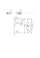
- FIG. 1 is a schematic diagram of a power supply system
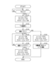
- FIG. 2 is a flowchart showing a process for controlling a relay.
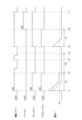
- FIG. 3 is a time chart for explaining relay control in more detail.
- FIG. 4 is a schematic configuration diagram of a power supply system according to a second embodiment;
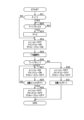
- FIG. 5 is a flowchart showing a process of relay control in the second embodiment.
- FIG. 6 is a time chart for more specifically explaining relay control in the second embodiment.
- FIG. 7 is a diagram showing the relationship between the current integrated value and the waiting time TB.
- This embodiment realizes a high-voltage power supply system that is mounted on an electrically powered vehicle such as an electric vehicle or a hybrid vehicle, and is configured to drive a high-voltage electrical load with power supplied from a high-voltage power supply in the high-voltage power supply system.
- Figure 1 shows a schematic configuration of the power supply system in this embodiment.
- a battery 11 which is a high-voltage power source, is connected to a positive electrode path 12 and a negative electrode path 13 as positive and negative electrical paths, and a high-voltage electrical load 21 is connected to each of the paths 12, 13.
- the battery 11 is, for example, a high-voltage lithium-ion storage battery with a storage voltage of several hundred volts.
- the high-voltage electrical load 21 includes an inverter that drives a vehicle driving motor (not shown).
- a main relay 15 is connected to the positive electrode path 12, and a ground relay 16 is connected to the negative electrode path 13.
- a series connection of a pre-charge relay 17 and a current limiting resistor 18 is also connected to the positive electrode path 12 in parallel with the main relay 15.
- the main relay 15 corresponds to the "power switch”
- the pre-charge relay 17 corresponds to the "pre-charge switch”.
- a capacitor 22 is connected in parallel to the high-voltage electrical load 21 between the positive electrode path 12 and the negative electrode path 13.
- This power supply system is provided with a control device 30 having a microcomputer, various memories, etc.
- a start signal is input to the control device 30 from a start switch 31 that starts the power supply system, and a current signal is input from a current sensor 32 provided in the negative electrode path 13, for example.
- the start switch 31 is a vehicle start switch (start switch) operated by a user to start the vehicle, or a linked switch that is turned on when the vehicle start switch is turned on.
- the start signal (on signal) input from the start switch 31 to the control device 30 corresponds to a "system start request.”
- the control device 30 is appropriately input with input information such as battery information indicating the voltage, temperature, etc. of the battery 11, and operating state information indicating the operating state of the driving motor that is the vehicle driving source.
- the control device 30 has a relay control function that controls the on/off of the main relay 15, ground relay 16, and precharge relay 17, and a load control function that controls the operation of the high-voltage electrical load 21.
- control device 30 When the control device 30 receives a start signal (system start request) output from the start switch 31, it turns on the ground relay 16 and pre-charge relay 17 before turning on the main relay 15. This causes current to flow from the battery 11 via the pre-charge relay 17 and current limiting resistor 18, pre-charging the capacitor 22. In other words, current flows through the pre-charge relay 17 before current flows through the main relay 15, charging the capacitor 22. In addition, the control device 30 turns on the main relay 15 and turns off the pre-charge relay 17 a predetermined time TA after the pre-charge relay 17 is turned on. This makes it possible to supply power from the battery 11 to the high-voltage electrical load 21.
- start signal system start request
- control device 30 is configured to include an abnormality determination unit that determines whether an electrical current abnormality has occurred in which electrical current continues to flow through the precharge relay 17 even after the precharge relay 17 has been turned on and the charging of the capacitor 22 has been completed, and a switch control unit that, if it is determined that an electrical current abnormality has occurred, turns off the precharge relay 17 and does not allow the precharge relay 17 to be turned on until a predetermined period of time has elapsed.
- the precharge relay 17 if an electrical current abnormality has occurred, the precharge relay 17 is not allowed to be turned on for the predetermined period of time until a waiting time TB set in a timer has elapsed, and the precharge relay 17 is allowed to be turned on after the waiting time TB has elapsed.
- FIG. 2 is a flowchart showing the process of relay control. This process is performed by the control device 30 at a predetermined interval after the start switch 31 is turned on.
- step S11 it is determined whether the waiting time TB set in the timer remains, in other words, whether the waiting time TB is greater than 0.
- This waiting time TB is set when an abnormality in electrical conduction occurs, and if the waiting time TB is 0, the process proceeds to the following step S12.
- step S12 the main relay 15 is turned off, and the ground relay 16 and precharge relay 17 are turned on. This starts precharging.
- step S13 the process waits for a predetermined time TA to elapse from when the precharge relay 17 is turned on, and in the following step S14, it is determined whether or not the current Ir flowing through the current limiting resistor 18 is less than a predetermined threshold value TH1 based on the detection value of the current sensor 32.
- the current Ir at the time when the predetermined time TA has elapsed is detection information of the current flowing through the current limiting resistor 18, and corresponds to a parameter indicating the amount of current flowing during the precharge current flow period.
- the predetermined time TA is determined based on the time required for the capacitor 22 to be precharged to completion, and at the time when the predetermined time TA has elapsed, the current Ir should be 0 or close to 0. In other words, if this power supply system is normal, the current Ir will be less than the threshold value TH1, step S14 will be judged as positive, and the process will proceed to step S15.
- step S15 the main relay 15 and ground relay 16 are turned on, and the precharge relay 17 is turned off. This enables power to be supplied from the battery 11 to the high-voltage electrical load 21.
- step S16 it is determined whether the start switch 31 is turned off. If the start switch 31 is turned off, the process proceeds to step S17, where the main relay 15, ground relay 16, and precharge relay 17 are all turned off.
- step S14 determines whether the current Ir is equal to or greater than the threshold value TH1
- the process proceeds to step S18.
- step S18 the main relay 15, the ground relay 16, and the precharge relay 17 are all turned off.
- step S19 a waiting time TB is set in a timer.
- the waiting time TB may be, for example, several tens of seconds to several minutes.
- step S19 the user may be notified that an abnormality has occurred. This notification may be made continuously until the waiting time TB has elapsed. The notification may be made by an on-board audio device or display device, or by a portable device carried by the user.
- step S11 is negative for the period until the standby time TB has elapsed after the start switch 31 is turned on thereafter. This prohibits current flow through the precharge relay 17 until the standby time TB has elapsed, i.e., until cooling of the current limiting resistor 18 is complete.
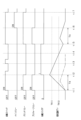
- FIG. 3 is a time chart for explaining the above relay control in more detail.
- FIG. 3 it is assumed that there is an abnormality in the electrical supply of the power supply system, but for the sake of comparison, the current change during normal operation is shown by a dashed line.
- the start switch 31 When the start switch 31 is in the OFF state, all of the relays 15 to 17 are in the OFF state as an initial state.
- the start switch 31 is turned on, turning on the ground relay 16 and precharge relay 17, and precharging begins.
- the current Ir rises suddenly at the beginning of the precharge, and then gradually decreases as the charging of the capacitor 22 progresses.
- the precharge is completed and the current Ir becomes 0 before the predetermined time TA has elapsed.
- the main relay 15 and ground relay 16 transition to an ON state, and the precharge relay 17 transitions to an OFF state. This makes it possible to supply power from the battery 11 to the high-voltage electrical load 21.
- the current Ir becomes larger after timing t1 compared to when the system is normal, and the current Ir continues to flow even after precharging is complete.
- the abnormal current is added to the original precharge current when the precharge relay 17 is turned on. Therefore, excess current flows while the precharge relay 17 is on, which promotes heat generation in the current limiting resistor 18.
- the current Ir becomes equal to or greater than the threshold value TH1, and all relays are turned off.
- a waiting time TB is set. Therefore, even if a system startup request occurs at timing t3 when the startup switch 31 is turned on, the precharge relay 17 remains off.
- the waiting time TB has elapsed, and the current limiting resistor 18 enters a cooled state.
- the ground relay 16 and pre-charge relay 17 are turned on and pre-charging begins.
- the abnormal current flow is resolved, and at timing t6 after a predetermined time TA has elapsed, the main relay 15 and ground relay 16 transition to an ON state and the pre-charge relay 17 transitions to an OFF state. This enables power to be supplied from the battery 11 to the high voltage electrical load 21.
- the main relay 15 and ground relay 16 are turned off as the start switch 31 is turned off.
- the temperature of the current limiting resistor 18 rises according to the amount of current flowing through the current limiting resistor 18. In this case, the presence or absence of a current abnormality is determined based on the detection information of the current flowing after the precharge relay 17 is turned on, so the occurrence of a current abnormality can be properly determined.
- the precharge relay 17 When it is determined that an electrical current abnormality has occurred, the precharge relay 17 is permitted to be turned on based on the passage of a predetermined period of time, i.e., the completion of cooling of the current limiting resistor 18. This makes it possible to prevent precharging from being unnecessarily restricted when the electrical current abnormality is temporary and is resolved. Therefore, it is possible to prevent the vehicle from becoming immobile after the current limiting resistor 18 has cooled.
- the system is configured to notify the user of the occurrence of the abnormality within the restricted period. This makes it possible to conveniently inform the user of the cause if the vehicle does not start despite the user turning on the start switch 31. It also makes it possible to prompt the user to have the problem repaired.
- Fig. 4 shows a schematic configuration of a power supply system in this embodiment.
- Fig. 4 differs from Fig. 1 in that a temperature sensor 41 is provided to detect the temperature (resistance temperature Tr) of the current limiting resistor 18 instead of the current sensor 32.
- a current abnormality is determined based on the resistance temperature Tr after the start of precharging, and the precharge relay 17 is not allowed to be turned on for a predetermined period until the resistance temperature Tr drops to a predetermined temperature after the determination, and the precharge relay 17 is allowed to be turned on after the resistance temperature Tr drops.
- FIG. 5 is a flowchart showing the procedure for relay control in the second embodiment. This process is performed by the control device 30 at a predetermined interval after the start switch 31 is turned on.
- step S21 it is determined whether the standby flag F is set to 1, in other words, whether it has been determined that a current flow abnormality has occurred due to the temperature of the current limiting resistor 18 prior to the present time, and whether this history has been stored as flag information.
- the standby flag F 0.
- step S24 the main relay 15 is turned off, and the ground relay 16 and precharge relay 17 are turned on. This starts precharging.
- step S25 the process waits for a predetermined time TA to elapse from when the precharge relay 17 is turned on, and in the following step S26, it is determined whether or not the resistance temperature Tr is less than a predetermined threshold value TH11 based on the detection value of the temperature sensor 41.
- the resistance temperature Tr at the time when the predetermined time TA has elapsed is detection information of the temperature of the current limiting resistor 18, and corresponds to a parameter indicating the amount of current flowing during the precharge current flow period.
- the threshold value TH11 is determined in advance based on the amount of current required to charge the capacitor 22. Note that the threshold value TH11 may be determined as a relative temperature based on the resistance temperature Tr at the start of the precharge. If the power supply system is normal, the resistance temperature Tr will be less than the threshold value TH11, step S26 will be judged as positive, and the process will proceed to step S27.
- step S27 the main relay 15 and ground relay 16 are turned on, and the precharge relay 17 is turned off. This enables power to be supplied from the battery 11 to the high-voltage electrical load 21.
- step S28 it is determined whether the start switch 31 is turned off. If the start switch 31 is turned off, the process proceeds to step S29, where the main relay 15, ground relay 16, and precharge relay 17 are all turned off.
- step S26 if it is determined in step S26 that the resistance temperature Tr is equal to or higher than the threshold value TH11, the process proceeds to step S30.
- step S30 the main relay 15, the ground relay 16, and the precharge relay 17 are all turned off.
- step S31 the standby flag F is set to 1. Also, in step S31, it is advisable to notify the user that an abnormality has occurred.
- step S21 is answered yes and the process proceeds to step S22 after the start switch 31 is turned on thereafter.
- step S22 it is determined whether the resistance temperature Tr is below a predetermined threshold value TH12.
- the threshold value TH12 is a temperature lower than the threshold value TH11 used in step S26.
- Step S22 is answered no during the period until the resistance temperature Tr falls below the threshold value TH12. This prohibits current flow through the precharge relay 17 until cooling of the current limiting resistor 18 is complete.
- the process proceeds to step S23 and the standby flag F is reset to 0. Thereafter, the process from step S24 onwards is carried out as described above.
- Figure 6 is a time chart for explaining the above relay control in more detail.
- Figure 6 we assume a situation where an abnormality in the electrical current is occurring in the power supply system, but for comparative explanation, the change in resistance temperature under normal conditions is shown by a dashed line.
- the start switch 31 is turned on, turning on the ground relay 16 and precharge relay 17, and precharging begins.
- the resistance temperature Tr gradually rises. If the system is normal, as shown by the dashed dotted line, the current flow is stopped as the precharge is completed before the specified time TA has elapsed, and the resistance temperature Tr changes from rising to falling. After that, although not shown, at timing t12, the main relay 15 and ground relay 16 are turned on, and the precharge relay 17 is turned off.
- the temperature rise rate becomes larger after timing t11 compared to when the system is normal, and the resistance temperature Tr continues to rise even after precharging is complete.
- the resistance temperature Tr becomes equal to or exceeds the threshold value TH11, and all relays are turned off.
- the standby flag F is set to 1. It is also possible to configure all relays to be turned off when the resistance temperature Tr rises to the threshold value TH11.
- the precharge relay 17 remains off because the standby flag F is 1 and the resistance temperature Tr is equal to or higher than the threshold value TH12. However, at timing t14, the resistance temperature Tr falls below the threshold value TH12 as the current limiting resistor 18 cools.
- the presence or absence of an electrical current abnormality is determined based on the detection information of the temperature of the current limiting resistor 18 after the precharge relay 17 is turned on, so that the occurrence of an electrical current abnormality can be properly determined.
- the pre-charge relay 17 is not permitted to be turned on for a predetermined period of time until the temperature (resistance temperature Tr) of the current limiting resistor 18 drops to a predetermined temperature, so that the pre-charge relay 17 can be effectively prevented from being turned on before the temperature drops.
- the current Ir at the time when a predetermined time TA has elapsed is acquired as a parameter indicating the magnitude of the current flowing during the pre-charge current flow period, but this may be changed.
- the current integrated value which is the integrated value of the current flowing after the pre-charge relay 17 is turned on, may be acquired as a parameter.
- the maximum value of the current flowing immediately after the pre-charge relay 17 is turned on may be acquired as a parameter.
- both detection information of the current flowing through the current limiting resistor 18 and detection information of the temperature of the current limiting resistor 18 are parameters indicating the magnitude of the current flow during the pre-charge current flow period. For example, it may be determined that a current flow abnormality has occurred on the condition that the current Ir is equal to or greater than a predetermined value and the resistance temperature Tr is equal to or greater than a predetermined value after a predetermined time TA has elapsed. Alternatively, it may be determined that a current flow abnormality has occurred based on either the current integrated value after the pre-charge relay 17 is turned on being equal to or greater than a predetermined value, or the resistance temperature Tr being equal to or greater than a predetermined value, whichever occurs first.
- the amount of heat generated by the current limiting resistor 18 changes depending on the amount of current flowing after the precharge relay 17 is turned on, and the length of the predetermined period required for the current limiting resistor 18 to cool also changes.
- the predetermined period may be variably set based on a parameter indicating the amount of current flowing during the precharge current flow period. For example, using the relationship shown in FIG. 7, the control device 30 may set the standby time TB to a longer time as the current integrated value after the precharge relay 17 is turned on increases.
- the standby time TB may be set to a longer time as the current Ir at the time when the predetermined time TA has elapsed increases, or the standby time TB may be set to a longer time as the resistance temperature Tr at the time when the predetermined time TA has elapsed increases.
- the predetermined period is set to a longer time as the integrated value of the current flowing after the precharge relay 17 is turned on (i.e., the amount of heat generated by the current limiting resistor 18) increases.
- the main relay 15 is provided in the positive path 12 as a power switch, and the precharge relay 17 and current limiting resistor 18 are connected in parallel to the main relay 15.
- this configuration may be changed to provide a ground relay 16 in the negative path 13 as a power switch, and the precharge relay 17 and current limiting resistor 18 may be connected in parallel to the ground relay 16.
- a configuration may be used in which only one of the main relay 15 on the positive side and the ground relay 16 on the negative side is provided, and that relay is used as a power switch.
- Switching devices other than relays may be used as power switches and precharge switches.
- semiconductor switches may be used.
- the present disclosure is applied to a high-voltage power supply system for an electric vehicle, but other applications are also possible. For example, it can be applied to power supply systems for various types of moving objects such as aircraft and ships, and power supply systems for stationary devices.
- control unit and the method described in the present disclosure may be realized by a dedicated computer provided by configuring a processor and memory programmed to execute one or more functions embodied in a computer program.
- control unit and the method described in the present disclosure may be realized by a dedicated computer provided by configuring a processor with one or more dedicated hardware logic circuits.
- control unit and the method described in the present disclosure may be realized by one or more dedicated computers configured by combining a processor and memory programmed to execute one or more functions with a processor configured with one or more hardware logic circuits.
- the computer program may be stored in a computer-readable non-transient tangible recording medium as instructions executed by the computer.
Landscapes
- Engineering & Computer Science (AREA)
- Power Engineering (AREA)
- Direct Current Feeding And Distribution (AREA)
Priority Applications (1)
| Application Number | Priority Date | Filing Date | Title |
|---|---|---|---|
| JP2024571680A JP7868703B2 (ja) | 2023-01-20 | 2023-12-26 | 制御装置及びプログラム |
Applications Claiming Priority (2)
| Application Number | Priority Date | Filing Date | Title |
|---|---|---|---|
| JP2023-007291 | 2023-01-20 | ||
| JP2023007291 | 2023-01-20 |
Publications (1)
| Publication Number | Publication Date |
|---|---|
| WO2024154560A1 true WO2024154560A1 (ja) | 2024-07-25 |
Family
ID=91955838
Family Applications (1)
| Application Number | Title | Priority Date | Filing Date |
|---|---|---|---|
| PCT/JP2023/046752 Ceased WO2024154560A1 (ja) | 2023-01-20 | 2023-12-26 | 制御装置及びプログラム |
Country Status (2)
| Country | Link |
|---|---|
| JP (1) | JP7868703B2 (cg-RX-API-DMAC7.html) |
| WO (1) | WO2024154560A1 (cg-RX-API-DMAC7.html) |
Cited By (1)
| Publication number | Priority date | Publication date | Assignee | Title |
|---|---|---|---|---|
| WO2026115900A1 (ja) * | 2024-11-29 | 2026-06-04 | パナソニックIpマネジメント株式会社 | 故障診断装置および電池パック |
Citations (2)
| Publication number | Priority date | Publication date | Assignee | Title |
|---|---|---|---|---|
| JP2005295697A (ja) * | 2004-03-31 | 2005-10-20 | Sanyo Electric Co Ltd | 車両用の電源装置 |
| JP2008253064A (ja) * | 2007-03-30 | 2008-10-16 | Toyota Motor Corp | 電源回路の制御装置および制御方法 |
-
2023
- 2023-12-26 WO PCT/JP2023/046752 patent/WO2024154560A1/ja not_active Ceased
- 2023-12-26 JP JP2024571680A patent/JP7868703B2/ja active Active
Patent Citations (2)
| Publication number | Priority date | Publication date | Assignee | Title |
|---|---|---|---|---|
| JP2005295697A (ja) * | 2004-03-31 | 2005-10-20 | Sanyo Electric Co Ltd | 車両用の電源装置 |
| JP2008253064A (ja) * | 2007-03-30 | 2008-10-16 | Toyota Motor Corp | 電源回路の制御装置および制御方法 |
Cited By (1)
| Publication number | Priority date | Publication date | Assignee | Title |
|---|---|---|---|---|
| WO2026115900A1 (ja) * | 2024-11-29 | 2026-06-04 | パナソニックIpマネジメント株式会社 | 故障診断装置および電池パック |
Also Published As
| Publication number | Publication date |
|---|---|
| JPWO2024154560A1 (cg-RX-API-DMAC7.html) | 2024-07-25 |
| JP7868703B2 (ja) | 2026-06-02 |
Similar Documents
| Publication | Publication Date | Title |
|---|---|---|
| CA2810841C (en) | Power circuit | |
| JP3953660B2 (ja) | 二輪自動車の後進制御装置 | |
| JP2007318849A (ja) | 電気自動車の電気システム | |
| JP7739917B2 (ja) | 車両制御装置 | |
| JP2009089535A (ja) | 車両用の電源装置 | |
| JP6828559B2 (ja) | 燃料電池システム、燃料電池システムの制御方法および燃料電池システム搭載車両 | |
| US8660751B2 (en) | Electric power steering apparatus and control method therefor | |
| JP2007159280A (ja) | 車両用電源装置 | |
| JP2005295697A (ja) | 車両用の電源装置 | |
| CN113169582A (zh) | 车载用的备用电源控制装置及车载用的备用电源装置 | |
| CN109921608B (zh) | 用于车辆的电源系统及电源系统的控制方法 | |
| JP2018174028A5 (cg-RX-API-DMAC7.html) | ||
| WO2018116741A1 (ja) | 電源システム | |
| US10518608B2 (en) | Vehicle air-conditioner safety device, and control method thereof | |
| JP7363955B2 (ja) | 給電制御装置、給電制御方法及びコンピュータプログラム | |
| US11251647B2 (en) | Vehicle electricity storage device | |
| JP7173421B1 (ja) | 給電制御装置 | |
| CN106121838B (zh) | 加热元件运转和发动机起动-停止可用性 | |
| JP4259006B2 (ja) | 電気自動車用電源制御装置 | |
| JP2003204681A (ja) | インバータの充放電制御回路 | |
| JP7298386B2 (ja) | 電力システム | |
| JP2013091424A (ja) | 電子制御装置 | |
| JP2015159642A (ja) | 車両用電源回路及び車両用電源回路の制御方法 | |
| US20260110730A1 (en) | Power supply control device | |
| JP6147317B2 (ja) | 給電制御装置 |
Legal Events
| Date | Code | Title | Description |
|---|---|---|---|
| 121 | Ep: the epo has been informed by wipo that ep was designated in this application |
Ref document number: 23917770 Country of ref document: EP Kind code of ref document: A1 |
|
| ENP | Entry into the national phase |
Ref document number: 2024571680 Country of ref document: JP Kind code of ref document: A |
|
| WWE | Wipo information: entry into national phase |
Ref document number: 2024571680 Country of ref document: JP |
|
| NENP | Non-entry into the national phase |
Ref country code: DE |
|
| 122 | Ep: pct application non-entry in european phase |
Ref document number: 23917770 Country of ref document: EP Kind code of ref document: A1 |