WO2024154394A1 - フィルム搬送機、フィルム搬送方法、及びフィルム製造装置 - Google Patents
フィルム搬送機、フィルム搬送方法、及びフィルム製造装置 Download PDFInfo
- Publication number
- WO2024154394A1 WO2024154394A1 PCT/JP2023/036483 JP2023036483W WO2024154394A1 WO 2024154394 A1 WO2024154394 A1 WO 2024154394A1 JP 2023036483 W JP2023036483 W JP 2023036483W WO 2024154394 A1 WO2024154394 A1 WO 2024154394A1
- Authority
- WO
- WIPO (PCT)
- Prior art keywords
- film
- conveyor
- lower roll
- downstream
- rolls
- Prior art date
- Legal status (The legal status is an assumption and is not a legal conclusion. Google has not performed a legal analysis and makes no representation as to the accuracy of the status listed.)
- Ceased
Links
Images
Classifications
-
- B—PERFORMING OPERATIONS; TRANSPORTING
- B29—WORKING OF PLASTICS; WORKING OF SUBSTANCES IN A PLASTIC STATE IN GENERAL
- B29C—SHAPING OR JOINING OF PLASTICS; SHAPING OF MATERIAL IN A PLASTIC STATE, NOT OTHERWISE PROVIDED FOR; AFTER-TREATMENT OF THE SHAPED PRODUCTS, e.g. REPAIRING
- B29C55/00—Shaping by stretching, e.g. drawing through a die; Apparatus therefor
- B29C55/02—Shaping by stretching, e.g. drawing through a die; Apparatus therefor of plates or sheets
- B29C55/10—Shaping by stretching, e.g. drawing through a die; Apparatus therefor of plates or sheets multiaxial
- B29C55/12—Shaping by stretching, e.g. drawing through a die; Apparatus therefor of plates or sheets multiaxial biaxial
- B29C55/14—Shaping by stretching, e.g. drawing through a die; Apparatus therefor of plates or sheets multiaxial biaxial successively
- B29C55/143—Shaping by stretching, e.g. drawing through a die; Apparatus therefor of plates or sheets multiaxial biaxial successively firstly parallel to the direction of feed and then transversely thereto
-
- B—PERFORMING OPERATIONS; TRANSPORTING
- B29—WORKING OF PLASTICS; WORKING OF SUBSTANCES IN A PLASTIC STATE IN GENERAL
- B29C—SHAPING OR JOINING OF PLASTICS; SHAPING OF MATERIAL IN A PLASTIC STATE, NOT OTHERWISE PROVIDED FOR; AFTER-TREATMENT OF THE SHAPED PRODUCTS, e.g. REPAIRING
- B29C48/00—Extrusion moulding, i.e. expressing the moulding material through a die or nozzle which imparts the desired form; Apparatus therefor
- B29C48/03—Extrusion moulding, i.e. expressing the moulding material through a die or nozzle which imparts the desired form; Apparatus therefor characterised by the shape of the extruded material at extrusion
- B29C48/07—Flat, e.g. panels
- B29C48/08—Flat, e.g. panels flexible, e.g. films
-
- B—PERFORMING OPERATIONS; TRANSPORTING
- B29—WORKING OF PLASTICS; WORKING OF SUBSTANCES IN A PLASTIC STATE IN GENERAL
- B29C—SHAPING OR JOINING OF PLASTICS; SHAPING OF MATERIAL IN A PLASTIC STATE, NOT OTHERWISE PROVIDED FOR; AFTER-TREATMENT OF THE SHAPED PRODUCTS, e.g. REPAIRING
- B29C48/00—Extrusion moulding, i.e. expressing the moulding material through a die or nozzle which imparts the desired form; Apparatus therefor
- B29C48/25—Component parts, details or accessories; Auxiliary operations
- B29C48/30—Extrusion nozzles or dies
- B29C48/305—Extrusion nozzles or dies having a wide opening, e.g. for forming sheets
-
- B—PERFORMING OPERATIONS; TRANSPORTING
- B29—WORKING OF PLASTICS; WORKING OF SUBSTANCES IN A PLASTIC STATE IN GENERAL
- B29C—SHAPING OR JOINING OF PLASTICS; SHAPING OF MATERIAL IN A PLASTIC STATE, NOT OTHERWISE PROVIDED FOR; AFTER-TREATMENT OF THE SHAPED PRODUCTS, e.g. REPAIRING
- B29C48/00—Extrusion moulding, i.e. expressing the moulding material through a die or nozzle which imparts the desired form; Apparatus therefor
- B29C48/25—Component parts, details or accessories; Auxiliary operations
- B29C48/36—Means for plasticising or homogenising the moulding material or forcing it through the nozzle or die
- B29C48/395—Means for plasticising or homogenising the moulding material or forcing it through the nozzle or die using screws surrounded by a cooperating barrel, e.g. single screw extruders
-
- B—PERFORMING OPERATIONS; TRANSPORTING
- B29—WORKING OF PLASTICS; WORKING OF SUBSTANCES IN A PLASTIC STATE IN GENERAL
- B29C—SHAPING OR JOINING OF PLASTICS; SHAPING OF MATERIAL IN A PLASTIC STATE, NOT OTHERWISE PROVIDED FOR; AFTER-TREATMENT OF THE SHAPED PRODUCTS, e.g. REPAIRING
- B29C48/00—Extrusion moulding, i.e. expressing the moulding material through a die or nozzle which imparts the desired form; Apparatus therefor
- B29C48/25—Component parts, details or accessories; Auxiliary operations
- B29C48/88—Thermal treatment of the stream of extruded material, e.g. cooling
-
- B—PERFORMING OPERATIONS; TRANSPORTING
- B29—WORKING OF PLASTICS; WORKING OF SUBSTANCES IN A PLASTIC STATE IN GENERAL
- B29C—SHAPING OR JOINING OF PLASTICS; SHAPING OF MATERIAL IN A PLASTIC STATE, NOT OTHERWISE PROVIDED FOR; AFTER-TREATMENT OF THE SHAPED PRODUCTS, e.g. REPAIRING
- B29C55/00—Shaping by stretching, e.g. drawing through a die; Apparatus therefor
- B29C55/02—Shaping by stretching, e.g. drawing through a die; Apparatus therefor of plates or sheets
- B29C55/20—Edge clamps
-
- B—PERFORMING OPERATIONS; TRANSPORTING
- B65—CONVEYING; PACKING; STORING; HANDLING THIN OR FILAMENTARY MATERIAL
- B65H—HANDLING THIN OR FILAMENTARY MATERIAL, e.g. SHEETS, WEBS, CABLES
- B65H20/00—Advancing webs
- B65H20/02—Advancing webs by friction roller
-
- B—PERFORMING OPERATIONS; TRANSPORTING
- B65—CONVEYING; PACKING; STORING; HANDLING THIN OR FILAMENTARY MATERIAL
- B65H—HANDLING THIN OR FILAMENTARY MATERIAL, e.g. SHEETS, WEBS, CABLES
- B65H20/00—Advancing webs
- B65H20/06—Advancing webs by friction band
-
- B—PERFORMING OPERATIONS; TRANSPORTING
- B65—CONVEYING; PACKING; STORING; HANDLING THIN OR FILAMENTARY MATERIAL
- B65H—HANDLING THIN OR FILAMENTARY MATERIAL, e.g. SHEETS, WEBS, CABLES
- B65H23/00—Registering, tensioning, smoothing or guiding webs
- B65H23/02—Registering, tensioning, smoothing or guiding webs transversely
- B65H23/032—Controlling transverse register of web
- B65H23/038—Controlling transverse register of web by rollers
Definitions
- the present invention relates to a film conveying machine, a film conveying method, and a film manufacturing device.
- Patent document 1 discloses a stretching machine that transports extruded film and stretches the film, and a clipping device that holds the film with clips.
- the present disclosure has been made to solve such problems, and has an object to provide a film transport device and the like that automatically feeds a film.
- a film transport device that transports a film from upstream to downstream, A robot arm having a conveyor on the underside of the tip thereof; A lower roll table provided below the conveyor and having a plurality of rolls;
- the feeding mechanism includes:
- an extruder that melts and extrudes the input resin raw material; a die connected to the extruder for forming the molten resin into a film; a cooling roll that cools the film-like molten resin extruded from the die and carries out a resin film in which the molten resin has solidified; a longitudinal stretching machine provided downstream of the cooling roll for longitudinally stretching the film and feeding the film downstream; a feed mechanism for feeding the film downstream, the feed mechanism including a robot arm having a conveyor under a tip portion thereof, and a lower roll table provided below the conveyor and having a plurality of rolls;
- the film feed mechanism further comprises a transverse stretching machine that is provided downstream of the feed mechanism and that transversely stretches the film and feeds it downstream.
- a film transport machine that automatically feeds film can be provided.
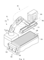
- FIG. 1 is a schematic perspective view showing an overall configuration of a film transporter and a film production apparatus according to a first embodiment.
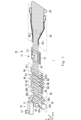
- FIG. 2 is a schematic perspective view showing the configuration of a film feed mechanism according to the first embodiment.
- 3A to 3C are schematic perspective views illustrating the operation of the film feed mechanism according to the first embodiment.
- FIG. 11 is a schematic perspective view showing a film feed mechanism and a clip device according to another embodiment.
- FIG. 13 is a top view illustrating the wrinkle-smoothing operation by the belt conveyor.
- FIG. 13 is a top view illustrating the wrinkle-smoothing operation by the belt conveyor.
- Fig. 1 is a schematic perspective view showing the overall configuration of the film manufacturing apparatus according to the first embodiment.
- the xyz Cartesian coordinate system shown in FIG. 1 and other drawings is for the convenience of explaining the positional relationship of the components.
- the positive direction of the z axis is vertically upward
- the xy plane is a horizontal plane, which is common between the drawings.
- the film may be a resin film and may include a resin sheet.
- the extruder 10 shown in FIG. 1 is a screw-type extruder.
- a screw extending in the x-axis direction is housed inside a cylinder 11 extending in the x-axis direction.
- a hopper 13 is provided above the end of the cylinder 11 on the negative x-axis direction side for feeding resin pellets, which are the raw material for the resin film 83.
- the resin pellets supplied from the hopper 13 are transported from the base to the tip of the rotating screw, i.e., in the positive direction of the x-axis. Inside the cylinder 11, the resin pellets are heated and sheared by the rotating screw, melting them and turning into molten resin 82.
- the screw is connected to a motor as a drive source via a reduction gear, for example.
- a heater for heating the inside of the cylinder 11 is provided on the outer circumferential surface of the cylinder 11 over almost the entire longitudinal area, and the resin pellets put into the cylinder 11 are heated.
- the T-die 20 is connected to the underside of the tip (end on the positive x-axis direction) of the extruder 10.
- a film-like molten resin 82a is extruded downward (negative z-axis direction) from a gap in the lip located at the lower end of the T-die 20.
- the lip spacing of the T-die 20 can be adjusted.
- the lip spacing of the T-die 20 can be adjusted at multiple points along the longitudinal direction of the lip (y-axis direction) so that the thickness of the produced resin film 83 in the width direction (y-axis direction) is uniform.
- the cooling machine 30 includes cooling rolls CR1 to CR4.
- the cooling roll CR1 cools the film-like molten resin 82a extruded from the T-die 20, and delivers the resin film 83 formed by solidifying the film-like molten resin 82a to the cooling roll CR2.
- the cooling roll CR1 is also called a cast roll.
- each of the cooling rolls CR1 to CR4 may be a driving roll driven by a driving source (not shown).
- the driving source is, for example, a variable speed motor such as a servo motor.
- Each of the cooling rolls CR1 to CR4 may be equipped with a cooling mechanism for cooling the resin film 83. Also, each of the cooling rolls CR1 to CR4 may be equipped with a heating mechanism for heating the resin film 83.
- the cooling machine 30 includes multiple drive rolls for transporting the resin film 83, and therefore may be one form of the film transport machine according to this embodiment.
- the longitudinal stretching machine 40 stretches the resin film 83 discharged from the cooling machine 30 in the longitudinal direction while transporting it.
- the longitudinal stretching machine 40 shown in FIG. 1 is equipped with eleven rolls R1 to R11. Each of the rolls R1 to R11 is a driving roll driven by a driving source (not shown).
- the driving source is, for example, a variable speed motor such as a servo motor.
- the longitudinal stretching machine 40 is one form of a film transport machine according to this embodiment.
- the longitudinal stretching machine 40 may be provided with multiple drive rolls for transporting the resin film 83, and the number and arrangement of the drive rolls provided in the longitudinal stretching machine 40 may be determined appropriately.
- Each of the rolls R1 to R11 may be provided with at least one of a cooling mechanism for cooling the resin film 83 and a heating mechanism for heating the resin film 83.
- the longitudinal stretching machine 40 may be provided with one or more nip rolls for pressing the resin film 83 against any of the rolls R1 to R11. The nip rolls are not drive rolls.
- the area in the film transport path where the film is longitudinally stretched by the longitudinal stretching machine 40 is also called the longitudinal stretching area.
- the feed mechanism 70 automatically feeds the resin film 83 discharged from the vertical stretching machine 40 to the subsequent horizontal stretching machine 50.
- the vertical stretching machine 40 and the horizontal stretching machine 50 have different feed mechanisms, so manual work by multiple people was required to feed the resin film 83 discharged from the vertical stretching machine 40 to the subsequent horizontal stretching machine 50.
- a new film feed mechanism 70 is provided that has the function of gripping and feeding the film. Details of this feed mechanism 70 will be described later.
- the feed mechanism 70 can be one form of a film transporter related to this embodiment.
- the transverse stretching machine 50 stretches the resin film 83 discharged from the feed mechanism 70 in its width direction (y-axis direction). More specifically, the transverse stretching machine 50 has a pair of rails RL1, RL2. A large number of clips (not shown) are slidably arranged in parallel across the entire rails RL1, RL2.
- the arrows on rails RL1 and RL2 indicate the movement direction of the clips.
- rails RL1 and RL2 have a loop structure with an outward path in which the clips move in the transport direction of the resin film 83 (positive direction of the x-axis) and a return path in the opposite direction (negative direction of the x-axis). That is, in the transverse stretching machine 50, the clips revolve around rails RL1 and RL2 having a loop structure.
- a clip closer (501 in FIG. 4) closes the tenter clips against the film.
- rails RL1 and RL2 have a symmetrical configuration with respect to a plane parallel to the xz plane.
- rails RL1 and RL2 are both arranged substantially parallel to each other on the outward path that travels in the conveying direction (positive direction of the x-axis) and the return path that travels in the opposite direction (negative direction of the x-axis).
- the return path of rail RL1 is arranged on the outer side in the width direction of the resin film 83 (negative direction of the y-axis).
- the return path of rail RL2 is also arranged on the outer side in the width direction of the resin film 83 (positive direction of the y-axis).
- the outward paths of rails RL1 and RL2 have a pair of parallel sections parallel to the x-axis at both ends in the longitudinal direction (x-axis direction), and a diagonal section diagonal in the y-axis direction between the parallel sections.
- the diagonal section of rail RL1 is diagonal in the negative y-axis direction
- the diagonal section of rail RL2 is diagonal in the positive y-axis direction.
- the distance between rails RL1 and RL2 in the y-axis direction becomes wider as they progress in the positive x-axis direction.
- the transverse stretching machine 50 shown in FIG. 1 has a drive source that drives clips for transporting the resin film 83.
- the drive source is, for example, a variable speed motor such as a servo motor.
- the transverse stretching machine 50 can be one form of the film transport machine according to this embodiment.
- the resin film 83 discharged from the transverse stretching machine 50 is wound up by the winding machine 60.
- the winding machine 60 is a drive roll driven by a drive source (not shown).
- the winding machine 60 may include a plurality of drive rolls driven by a drive source. In that case, the winding machine 60 can be one form of the film transport machine according to this embodiment.
- the area in the film transport path where the film is transversely stretched by the transverse stretching machine 50 is also called the transverse stretching area.
- some or all of the cooling machine 30, the longitudinal stretching machine 40, the feed mechanism 70, the transverse stretching machine 50, and the winding machine 60 may be one aspect of the film transport machine according to this embodiment.
- ⁇ Overall configuration of the feed mechanism> 2 is a schematic perspective view showing a configuration of a film feeding mechanism.
- the feeding mechanism 70 may be provided downstream of the longitudinal stretching machine 40 and upstream of the transverse stretching machine 50 in the film transport path.
- the feed mechanism 70 includes a robot arm 715 having a belt conveyor 711 below its tip, and a lower roll table 720 that is provided below the belt conveyor 711 and has multiple rolls and can be raised and lowered.
- the lower roll table 720 can be raised and lowered vertically by a lifting mechanism 725.
- the lifting mechanism 725 includes three lifting units that can be raised and lowered synchronously.
- the lower roll table 720 includes multiple lower right rolls RUR and lower left rolls LUR arranged in two rows so that a film can be placed on it and fed.
- the robot arm 715 may be a six-axis vertical articulated robot arm.
- the robot arm 715 includes a base 7150 fixed on the floor, a first link 7151 rotatably and tiltably attached to the base 7150, a second link 7152 tiltably and tiltably attached to the tip of the first link 7151, and a wrist 7153 tiltably attached to the tip of the second link 7152. Any of various known robot arms may be used as the robot arm.
- the belt conveyor 711 is connected to the tip of the robot arm 715 via an attachment part 712.
- the belt conveyor 711 includes a number of rolls 711R, 711R provided at both ends, and a belt 7111 stretched across the rolls.
- the roll 711R is a roll with a built-in motor.
- the belt conveyor may be any of various known belt conveyors.
- Guide rolls 729, 729 are provided to guide the film sent from the longitudinal stretching machine 40.
- two meandering detection units 90 are provided after the guide rolls 729, 729.
- One or more meandering detection units 90 can be disposed immediately after the longitudinal stretching machine 40 or between the longitudinal stretching machine 40 and the transverse stretching machine 50.
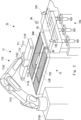
- FIG. 3 is a schematic perspective view showing the operation of the film feeding mechanism.
- the feed mechanism 70 loads the film 83 fed from upstream as the lower roll table 720 rises.
- the robot arm 715 lowers its tip to hold the film 83 between the belt conveyor 711 and the lower roll table 720, and conveys the film 83 downstream as the belt conveyor 711 rotates.
- the film 83 sent from the vertical stretching machine 40 is sent along guide rolls 729, 729 provided at both ends of the path to above the lower roll platform 720 of the lower roller mechanism 72.
- the lifting mechanism 725 is driven to raise the lower roll platform 720 to a predetermined position, allowing the film 83 to be placed on the lower roll platform 720.
- the film 83 moves downstream on the rolls of the lower roll platform 720 by the vertical stretching machine 40.
- the rolls on the lower roll platform 720 may include multiple lower right rolls RUR and multiple lower left rolls LUR arranged in two rows. Each roll may be a drive roll driven by a drive source not shown, or a free roll without a drive source.
- the robot arm 715 lowers the belt conveyor 711 at its tip. Specifically, as shown in FIG. 3, the belt conveyor 711 descends approximately parallel to the multiple lower right rolls RUR of the lower roll table 720, gripping the film 83 during that time.
- the belt conveyor 711 drives the multiple rolls 711R, 711R, the belt 7111 and the film 83 gripped by the multiple lower right rolls RUR are sent downstream. Note that if the multiple lower right rolls RUR have a drive source, the multiple lower right rolls RUR may rotate in synchronization with the multiple rolls 711R of the belt conveyor 711.
- the robot mechanism 71 may have two branched second links 7152, 7152 corresponding to multiple lower right rolls RUR and lower left roll LUR, respectively.
- the underside of the robot arm may have a first conveyor corresponding to multiple left rolls and a second conveyor corresponding to multiple right rolls.
- the first conveyor and second conveyor are each configured to be rotatable about a vertical axis.
- wrinkles in the film can be removed by sending the film downstream while gripping it between multiple lower right rolls RUR and the belt conveyor 711.
- a meandering detection unit 90 (e.g., various sensors such as a camera, a laser sensor, an edge sensor, etc.) that detects the presence or absence of meandering of the film may be provided above the lower roll table 720.
- the meandering detection unit 90 is an edge sensor that detects both ends of the film after the longitudinal stretching region.
- the robot arm 715 may perform an axial rotation in the vertical direction while pressing the belt conveyor 711 against the film 83 placed on the lower roll table 720 based on the detection result.
- the robot arm 715 performs an axial rotation in the vertical direction clockwise while pressing the belt conveyor 711 against the film 83 placed on the lower roll table 720.
- the operation of the robot arm 715 is controlled by a control unit (not shown).
- the control unit receives sensor signals from various sensors such as the meandering detection unit 90, and can control the operation of various drive units related to the robot arm, etc. based on the sensor signals.
- the control unit can execute various controls based on various programs stored in the storage unit, and is realized by a central processing unit (CPU), read-only memory (ROM), random access memory (RAM), input/output ports (I/O), etc.
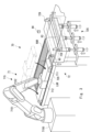
- FIG. 4 is a schematic perspective view showing a film feeding mechanism and a clip device according to another embodiment.
- Clip devices 800 are disposed on both ends of the film following the aforementioned feed mechanism 70. Although only the clip device 800 for the left end of the film is shown in Fig. 4, the clip device 800 for the right end of the film may also be disposed approximately symmetrically.
- the feed mechanism 70 uses the belt conveyor 711 and lower roll table 720 to feed the film to the position of the clip closer 501 while gripping it.
- One clip closer 501 closes a clip on one end of the gripped film.
- the other clip closer 501 closes a clip on the other end of the gripped film.
- the feed mechanism 70 can move the film downstream. In this way, the feed mechanism 70 can assist the clip closer in the clipping action for lateral stretching. This eliminates the need for manual work by multiple people and enables smooth transport of the film.
- a wrinkle detection unit 7121 (e.g., a camera) that detects wrinkles in the film 83 may be provided above the lower roll table 720 (e.g., below the mounting portion 712 of the robot arm 715).
- the wrinkle detection unit 7121 (e.g., a camera or edge sensor) may be provided in a location away from the robot arm 715 (e.g., on the ceiling, etc.) between the longitudinal stretching machine 40 and the robot arm 715.
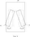
- the robot arm 715 Based on the captured image of the film, the robot arm 715 can also perform vertical axial rotation while pressing the belt conveyor 711 against the film 83 placed on the lower roll table 720, as shown in FIG. 5. This makes it possible to remove localized wrinkles in the film.
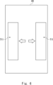
- the two belt conveyors 711, 711 can move to the left and right as shown in FIG. 6 while holding down the film, thereby removing wrinkles in the film. It should be noted that one of the two belt conveyors may be fixed near one edge of the film while the other belt conveyor is moved toward the other edge of the film to remove wrinkles from the film.
- the operation of the robot arm 715 is controlled by a control unit (not shown).
- the control unit receives sensor signals from various sensors such as the wrinkle detection unit 7121, and can control the driving of various driving units related to the robot arm, etc. based on the sensor signals.
- the program includes instructions (or software code) that, when loaded into a computer, cause the computer to perform one or more functions described in the embodiments.
- the program may be stored on a non-transitory computer-readable medium or tangible storage medium.
- computer-readable medium or tangible storage medium may include random-access memory (RAM), read-only memory (ROM), flash memory, solid-state drive (SSD) or other memory technology, CD-ROM, digital versatile disc (DVD), Blu-ray® disk or other optical disk storage, magnetic cassette, magnetic tape, magnetic disk storage or other magnetic storage device.
- the program may be transmitted on a transitory computer-readable medium or communication medium.
- the transitory computer-readable medium or communication medium may include electrical, optical, acoustic, or other forms of propagated signals.
- a film transport method for transporting a film from upstream to downstream using a film transport machine equipped with a robot arm having a conveyor under its tip and a lower roll table that is movable and lowered and has multiple romens and is provided below the film the lower roll table rises to place the film transported from upstream, and the robot arm descends to grip the film between the conveyor and the lower roll table, while the conveyor rotates to transport the film downstream.
- the film manufacturing apparatus includes an extruder that melts and extrudes an input resin raw material, a die connected to the extruder that forms the molten resin into a film, a cooling roll that cools the film-like molten resin extruded from the die and conveys a resin film in which the molten resin has solidified, a vertical stretching machine that is provided downstream of the cooling roll and vertically stretches the film and sends it downstream, a feed mechanism that sends the film downstream and includes a robot arm with a conveyor under its tip and a lower roll table that is provided below the conveyor and has multiple rolls and can be raised and lowered, and a horizontal stretching machine that is provided downstream of the feed mechanism and horizontally stretches the film and sends it downstream.
Landscapes
- Engineering & Computer Science (AREA)
- Mechanical Engineering (AREA)
- Physics & Mathematics (AREA)
- Thermal Sciences (AREA)
- Manufacturing & Machinery (AREA)
- Shaping By String And By Release Of Stress In Plastics And The Like (AREA)
- Registering, Tensioning, Guiding Webs, And Rollers Therefor (AREA)
- Extrusion Moulding Of Plastics Or The Like (AREA)
Priority Applications (2)
| Application Number | Priority Date | Filing Date | Title |
|---|---|---|---|
| DE112023005593.9T DE112023005593T5 (de) | 2023-01-17 | 2023-10-06 | Folientransportmaschine, folientransportverfahren und vorrichtung zur folienherstellung |
| CN202380091496.5A CN120569283A (zh) | 2023-01-17 | 2023-10-06 | 薄膜输送机、薄膜输送方法和薄膜制造装置 |
Applications Claiming Priority (2)
| Application Number | Priority Date | Filing Date | Title |
|---|---|---|---|
| JP2023-004857 | 2023-01-17 | ||
| JP2023004857A JP2024101115A (ja) | 2023-01-17 | 2023-01-17 | フィルム搬送機、フィルム搬送方法、及びフィルム製造装置 |
Publications (1)
| Publication Number | Publication Date |
|---|---|
| WO2024154394A1 true WO2024154394A1 (ja) | 2024-07-25 |
Family
ID=91955674
Family Applications (1)
| Application Number | Title | Priority Date | Filing Date |
|---|---|---|---|
| PCT/JP2023/036483 Ceased WO2024154394A1 (ja) | 2023-01-17 | 2023-10-06 | フィルム搬送機、フィルム搬送方法、及びフィルム製造装置 |
Country Status (4)
| Country | Link |
|---|---|
| JP (1) | JP2024101115A (enExample) |
| CN (1) | CN120569283A (enExample) |
| DE (1) | DE112023005593T5 (enExample) |
| WO (1) | WO2024154394A1 (enExample) |
Citations (5)
| Publication number | Priority date | Publication date | Assignee | Title |
|---|---|---|---|---|
| JPS5757260B2 (enExample) * | 1977-04-05 | 1982-12-03 | Imuperiaru Chem Ind Plc | |
| WO2011125662A1 (ja) * | 2010-03-31 | 2011-10-13 | 宇部興産株式会社 | 延伸装置およびそれを用いたポリイミドフィルムの製造方法 |
| JP2013082149A (ja) * | 2011-10-11 | 2013-05-09 | Ube Industries Ltd | 延伸装置およびそれを用いたポリイミドフィルムの製造方法 |
| JP2018154476A (ja) * | 2017-03-21 | 2018-10-04 | 東レ株式会社 | ウェブロール体の製造方法 |
| JP2022094641A (ja) * | 2020-12-15 | 2022-06-27 | 株式会社トッパンTomoegawaオプティカルフィルム | ロール装置 |
-
2023
- 2023-01-17 JP JP2023004857A patent/JP2024101115A/ja active Pending
- 2023-10-06 DE DE112023005593.9T patent/DE112023005593T5/de active Pending
- 2023-10-06 WO PCT/JP2023/036483 patent/WO2024154394A1/ja not_active Ceased
- 2023-10-06 CN CN202380091496.5A patent/CN120569283A/zh active Pending
Patent Citations (5)
| Publication number | Priority date | Publication date | Assignee | Title |
|---|---|---|---|---|
| JPS5757260B2 (enExample) * | 1977-04-05 | 1982-12-03 | Imuperiaru Chem Ind Plc | |
| WO2011125662A1 (ja) * | 2010-03-31 | 2011-10-13 | 宇部興産株式会社 | 延伸装置およびそれを用いたポリイミドフィルムの製造方法 |
| JP2013082149A (ja) * | 2011-10-11 | 2013-05-09 | Ube Industries Ltd | 延伸装置およびそれを用いたポリイミドフィルムの製造方法 |
| JP2018154476A (ja) * | 2017-03-21 | 2018-10-04 | 東レ株式会社 | ウェブロール体の製造方法 |
| JP2022094641A (ja) * | 2020-12-15 | 2022-06-27 | 株式会社トッパンTomoegawaオプティカルフィルム | ロール装置 |
Also Published As
| Publication number | Publication date |
|---|---|
| DE112023005593T5 (de) | 2025-10-30 |
| CN120569283A (zh) | 2025-08-29 |
| JP2024101115A (ja) | 2024-07-29 |
Similar Documents
| Publication | Publication Date | Title |
|---|---|---|
| CN204324482U (zh) | 向裁断机的开匹搬入装置 | |
| KR102228558B1 (ko) | 고무 시트 부재의 공급장치 및 방법 | |
| JP6691362B2 (ja) | コイル材搬送装置、プレスシステム、およびコイル材搬送方法 | |
| WO2024154394A1 (ja) | フィルム搬送機、フィルム搬送方法、及びフィルム製造装置 | |
| JP6518462B2 (ja) | 長尺ワークの搬送装置 | |
| WO2024154395A1 (ja) | フィルム搬送機、フィルム搬送方法、及びフィルム製造装置 | |
| WO2020116071A1 (ja) | セパレータフィルム製造装置及びセパレータフィルムの製造方法 | |
| JP4203229B2 (ja) | シート状物の搬送装置 | |
| JP7334609B2 (ja) | ガラス板の梱包装置 | |
| JP2024101115A5 (enExample) | ||
| CN116214950A (zh) | 树脂膜搬运机、其控制方法及树脂膜制造装置 | |
| JP4141282B2 (ja) | 帯状押出物滞留装置 | |
| JPH0625957Y2 (ja) | フープ材搬送装置 | |
| JP2002144417A (ja) | テンタ | |
| WO2022168358A1 (ja) | 樹脂フィルム延伸装置用リンク機構、樹脂フィルム延伸装置および樹脂フィルムの製造方法 | |
| JP2014043024A (ja) | 押出成形装置、成形品及び成形品の成形方法 | |
| JP2002226101A (ja) | テンタ | |
| JP2024042057A (ja) | 延伸装置 | |
| CN119897986A (zh) | 树脂薄膜制造装置及其控制方法 | |
| JP4136489B2 (ja) | 未加硫ゴムシート製造装置、及び未加硫ゴムシートの製造方法 | |
| JP5641770B2 (ja) | 押出材の製造方法 | |
| JP3076714U (ja) | 薄肉厚樹脂シート用熱成形装置 | |
| JP5555540B2 (ja) | 矩形状生地部材の折り畳み方法及び装置 | |
| JPH05254701A (ja) | 帯状部材の成形巻取り装置 | |
| JP2003136129A (ja) | 押出し材の搬送装置 |
Legal Events
| Date | Code | Title | Description |
|---|---|---|---|
| 121 | Ep: the epo has been informed by wipo that ep was designated in this application |
Ref document number: 23917606 Country of ref document: EP Kind code of ref document: A1 |
|
| WWE | Wipo information: entry into national phase |
Ref document number: 202380091496.5 Country of ref document: CN |
|
| WWE | Wipo information: entry into national phase |
Ref document number: 202517071056 Country of ref document: IN |
|
| WWP | Wipo information: published in national office |
Ref document number: 202517071056 Country of ref document: IN |
|
| WWE | Wipo information: entry into national phase |
Ref document number: 112023005593 Country of ref document: DE |
|
| WWP | Wipo information: published in national office |
Ref document number: 202380091496.5 Country of ref document: CN |
|
| WWP | Wipo information: published in national office |
Ref document number: 112023005593 Country of ref document: DE |