WO2024154340A1 - ボールねじアクチュエータ - Google Patents
ボールねじアクチュエータ Download PDFInfo
- Publication number
- WO2024154340A1 WO2024154340A1 PCT/JP2023/001727 JP2023001727W WO2024154340A1 WO 2024154340 A1 WO2024154340 A1 WO 2024154340A1 JP 2023001727 W JP2023001727 W JP 2023001727W WO 2024154340 A1 WO2024154340 A1 WO 2024154340A1
- Authority
- WO
- WIPO (PCT)
- Prior art keywords
- passage
- ball
- return
- ball screw
- lubricating oil
- Prior art date
- Legal status (The legal status is an assumption and is not a legal conclusion. Google has not performed a legal analysis and makes no representation as to the accuracy of the status listed.)
- Ceased
Links
Images






Classifications
-
- F—MECHANICAL ENGINEERING; LIGHTING; HEATING; WEAPONS; BLASTING
- F16—ENGINEERING ELEMENTS AND UNITS; GENERAL MEASURES FOR PRODUCING AND MAINTAINING EFFECTIVE FUNCTIONING OF MACHINES OR INSTALLATIONS; THERMAL INSULATION IN GENERAL
- F16C—SHAFTS; FLEXIBLE SHAFTS; ELEMENTS OR CRANKSHAFT MECHANISMS; ROTARY BODIES OTHER THAN GEARING ELEMENTS; BEARINGS
- F16C29/00—Bearings for parts moving only linearly
- F16C29/04—Ball or roller bearings
- F16C29/06—Ball or roller bearings in which the rolling bodies circulate partly without carrying load
-
- F—MECHANICAL ENGINEERING; LIGHTING; HEATING; WEAPONS; BLASTING
- F16—ENGINEERING ELEMENTS AND UNITS; GENERAL MEASURES FOR PRODUCING AND MAINTAINING EFFECTIVE FUNCTIONING OF MACHINES OR INSTALLATIONS; THERMAL INSULATION IN GENERAL
- F16H—GEARING
- F16H25/00—Gearings comprising primarily only cams, cam-followers and screw-and-nut mechanisms
- F16H25/18—Gearings comprising primarily only cams, cam-followers and screw-and-nut mechanisms for conveying or interconverting oscillating or reciprocating motions
- F16H25/20—Screw mechanisms
- F16H25/24—Elements essential to such mechanisms, e.g. screws, nuts
Definitions
- the present invention relates to a ball screw actuator, and more specifically to a lubricant supply structure for a linear ball bearing incorporated in the ball screw actuator.
- a known linear motion actuator is a ball screw actuator that includes a linear guide rail having a concave cross-sectional shape with left and right side walls, a slider arranged between the left and right side walls of the guide rail, and a plurality of balls that circulate between the left and right side walls of the guide rail and the slider, left and right linear ball bearings that guide the axial movement of the slider relative to the guide rail, a ball screw nut portion provided on the slider, and a ball screw shaft that passes axially through a through hole provided in the center of the slider in the left and right direction and screws into the ball screw nut portion provided on the slider via balls (for example, Patent Document 1).
- the slider provided in this ball screw actuator has a slider body that holds the ball screw nut portion, and ball return members that are attached to both axial ends of the slider body and have return passages for the left and right linear ball bearings.
- the structure for supplying lubricating oil such as grease to the left and right linear ball bearings of the above-mentioned ball screw actuator includes a lubricating oil injection passage provided in the ball return member and a lubricating oil supply passage that supplies lubricating oil from the lubricating oil injection passage to the return passages of the left and right linear ball bearings (hereinafter sometimes referred to as the left and right return passages).
- lubricating oil In order for the left and right linear ball bearings of a ball screw actuator to be lubricated evenly, lubricating oil must be supplied evenly to the left and right return passages.
- the left and right linear ball bearings are arranged symmetrically with respect to the through hole through which the ball screw shaft passes, so if the lubricating oil injection passage extending in the axial direction is on a symmetrical line passing through the center of the through hole, the left and right return passages are arranged symmetrically with respect to the through hole, that is, if the passage length from the lubricating oil injection passage to the return passage is the same for the left and right return passages, lubricating oil will be supplied equally to the left and right return passages.
- the problem that this invention aims to solve is to ensure that lubricating oil is supplied evenly to the left and right linear ball bearings even if the lubricating oil injection passage is biased to one side of the through hole.
- the slider body includes a ball return member attached to each of both ends of the slider body in the axial direction, and at least one of the ball return members has left and right return passages in which the balls of the left and right linear ball bearings move, which are provided symmetrically with respect to the through hole, a lubricant injection passage provided biased to one of the left and right sides with respect to the through hole, and a lubricant supply passage that supplies lubricant from the lubricant injection passage to the left and right return passages, and the lubricant supply passage has a first passage that runs from the lubricant injection passage to a branch position on a symmetric line that passes through the center of the through hole, and a second passage that is symmetrical and branches left and right from the branch position to the left and right return passages.
- the second passage may preferably be connected to the outer ends of the left and right return passages.
- the partition may preferably be formed of a partition member attached to the ball return member.
- This aspect makes it easier to form the partition wall.
- a third passage extending symmetrically from the second passage radially outward of the through hole, and a fourth passage extending from a symmetrical position of the third passage to the through hole.
- lubricating oil is also supplied to the ball screw shaft through the through hole.
- the first passage, the second passage, the third passage and the fourth passage include a portion formed by a groove that opens into the surface where the ball return member abuts against the end face of the slider body, and the groove may define a lubricating oil supply passage whose opening is closed by the end face of the slider body.
- a lubricating oil supply passage having a closed cross-sectional shape can be easily formed with a high degree of freedom.
- the first passage and the second passage include overlapping portions in the front and rear of the axial direction, and the first passage and the second passage in the overlapping portions are separated by a partition member attached to the ball return member, and the portion is formed by a recessed groove provided in the partition member.
- the portion where the second passage overlaps with the first passage can be easily formed without interfering with the first passage.
- each of the seal plates may have an opening with an inner diameter smaller than that of the through hole.
- This aspect prevents the lubricating oil supplied to the through hole of the ball return member from flowing excessively toward the slider body.
- the left and right linear ball bearings are each configured in two upper and lower stages
- the ball return member has return passages in two upper and lower stages
- the second passage leads symmetrically between the upper and lower two stages of return passages and is connected to the upper and lower two stages of return passages.
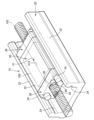
- FIG. 1 is a perspective view showing a first embodiment of a ball screw actuator according to the present invention
- FIG. 1 is an enlarged exploded perspective view of a main part of a ball screw actuator according to a first embodiment
- FIG. 1 is a perspective view of a main portion of a ball return member of a ball screw actuator according to a first embodiment
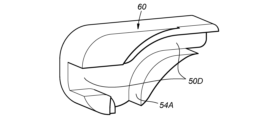
- FIG. 1 is a perspective view of a main portion of a partition member of a ball screw actuator according to a first embodiment
- FIG. 1 is a front view of a ball return member of a ball screw actuator according to a first embodiment
- 6 is a cross-sectional view taken along line VI-VI of FIG. FIG.
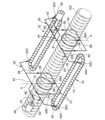
- FIG. 11 is a perspective view showing a ball screw actuator according to a second embodiment of the present invention
- FIG. 11 is a perspective view of a ball return member of the ball screw actuator according to the second embodiment
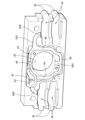
- FIG. 11 is a front view of a ball return member of the ball screw actuator according to the second embodiment
- Figure 7 is a skeleton diagram showing an overview of the ball circulation path and lubricating oil passage of the linear ball bearing, and does not include the slider 30 and side wall 22, which will be described later.
- the ball screw actuator 10 of the first embodiment comprises a linear guide rail 20 having a concave cross-sectional shape with left and right side walls 22, a slider 30 disposed between the left and right side walls 22 of the guide rail 20, and left and right linear ball bearings 70 each having a plurality of balls 72 (see FIG. 7) that circulate between the left and right side walls 22 of the guide rail 20 and the slider 30, and guiding the axial movement of the slider 30 relative to the guide rail 20.
- the ball screw actuator 10 further includes a ball screw nut portion 100 provided on the slider 30, and a ball screw shaft 102 that passes axially through a through hole 31 provided on the slider 30 and screws into the ball screw nut portion 100 provided on the slider 30 via balls 104 (see FIG. 6).
- the ball screw shaft 102 is driven to rotate by an electric motor (not shown) that is attached to the shaft end of the guide rail 20.
- the ball screw nut portion 100 may be integral with the slider 30.
- the slider 30 has a roughly rectangular prism-shaped slider body 32 including a ball screw nut portion 100, and roughly rectangular prism-shaped front and rear ball return members 36 fixed to both axial ends (front and rear ends) of the slider body 32 by a number of bolts 34.
- each ball return member 36 has a through hole 38 that passes through the approximate center in the axial direction and forms part of the above-mentioned through hole 31.
- the through hole 38 has an inner diameter that is approximately the same as or smaller than the through hole 31A of the part of the through hole 31 that passes through the slider body 32, and is provided approximately coaxially (approximately concentrically) with the through hole 31A.
- Each ball return member 36 further has left and right return passages 40 that are provided symmetrically with respect to the through hole 38 and through which the balls 72 of the left and right linear ball bearings 70 can roll, a lubricant injection passage 42 that extends in the axial direction and is biased to one of the left and right sides with respect to the through hole 38, and a lubricant supply passage 44 that supplies lubricant such as grease from the lubricant injection passage 42 to the left and right return passages 40.
- a lubricant nipple 46 (see Figures 1 and 7) that communicates with the corresponding lubricant injection passage 42 is attached to the outer wall of each ball return member 36.
- each of the left and right linear ball bearings 70 has an external passage 74 formed to extend in the axial direction between the corresponding side wall 22 (see FIG. 1) of the guide rail 20 and the slider body 32 (see FIG. 1), and an internal passage 76 formed to extend (through) the inside of the slider body 32 (see FIG. 1) in the axial direction.
- Each external passage 74 is formed by a groove 24 (see FIG. 1) with a substantially semicircular cross section formed on the inner surface of the side wall 22 and a groove (not shown) with a substantially semicircular cross section formed on the outer surface of the slider body 32.
- the inner surface of the side wall 22 and the outer surface of the slider body 32 are not in contact with each other, and an air gap G (see FIG. 5) is formed between the inner surface of the side wall 22 and the outer surface of the slider body 32, extending in the axial direction with a gap width in the left-right direction.
- the left and right return passages 40 are each a passage with a roughly semicircular (U-shaped) planar shape in which the balls 72 can roll, defined by a groove 41 with a roughly semicircular planar shape formed in the ball return member 36 and a passage defining member 43 with a roughly semicircular planar shape attached to the ball return member 36.
- Each return passage 40 has an outer end 40A that communicates with the corresponding external passage 74 and an inner end 40B that communicates with the corresponding internal passage 76.
- Each ball return member 36 has a ball drop prevention section 39 with a roughly semicircular cross-sectional shape that protrudes outward from the left and right outer walls to prevent the balls 72 of the linear ball bearings 70 from dropping outward from the outer ends 40A of the left and right return passages 40.
- the left and right linear ball bearings 70 each have an external passage 74, an internal passage 76, and front and rear return passages 40 that communicate with each other, forming a closed loop circulation path through which multiple balls 72 circulate.
- the lubricating oil supply passage 44 has a first passage 48 that extends to the right from the lubricating oil injection passage 42 as viewed in Figures 5 and 7, passes through the center of the through hole 38, and reaches a branching position B on a left-right symmetrical line A that extends in the vertical direction, and a left-side second passage 50 and a right-side second passage 52 that branch off to the left and right from branching position B and reach the left and right return passages 40.
- the left second passage 50 has a leftward extension portion 50A that extends leftward from the branch position B, and an inclined extension portion 50B that bends diagonally downward from the left end of the leftward extension portion 50A and reaches the left return passage 40.
- the inclined extension portion 50B includes a communicating end 50C that communicates with a portion of the return passage 40 near the left outer end portion 40A.
- the right-side second passage 52 has a right-side extension portion 52A that extends rightward from the branch position B, and an inclined extension portion 52B that bends diagonally downward from the right end of the right-side extension portion 52A and reaches the right-side return passage 40.
- the inclined extension portion 52B includes a communicating end 52C that communicates with the return passage 40 near the right-side outer end portion 40A.
- the communication end 52C may open at a position on the outer end 40A of the right return passage 40, which is closer to the position that divides the inner end 40B and the outer end 40A in half.
- the communication end 52C preferably communicates with the return passage 40 at the right outer end 40A, which is closest to the air gap G of the right external passage 74, as shown by the phantom line in FIG. 5.
- the lubricating oil supply passage 44 further includes a left third passage 54 and a right third passage 56 which extend vertically symmetrically from the left second passage 50 and the right second passage 52 radially outward of the through hole 38, and a fourth passage 58 which extends horizontally and connects the lower ends of the left third passage 54 and the right third passage 56 to each other.
- the fourth passage 58 includes an opening end 58A which opens toward the lower portion of the through hole 38, and leads to the through hole 38.
- the first passage 48, the second left passage 50, the second right passage 52, the third left passage 54, the third right passage 56 and the fourth passage 58 each include a portion formed by a groove that opens into a surface of the ball return member 36 that joins to the end face of the slider body 32.
- the groove defines a lubricant supply passage having a closed cross-sectional shape by having the opening closed by the end face of the slider body 32. This makes it easy to configure a lubricant supply passage with a high degree of freedom.
- the first passage 48 and the leftward extension 50A of the left-side second passage 50 include overlapping portions in the axial front and rear.
- the overlapping portions of the first passage 48 and the leftward extension 50A of the left-side second passage 50 are isolated as much as possible as separate passages by a partition member 60 (see FIG. 4) fitted into a recess 62 (see FIG. 3) formed in the ball return member 36.
- the recess 62 of the ball return member 36 has a deep bottom surface 62A where the lubricating oil injection passage 42 opens, and a shallow bottom surface 62B formed on a part of the outer periphery of the deep bottom surface 62A.
- the partition member 60 abuts against the shallow bottom surface 62B, and defines the first passage 48 between the back surface of the partition member 60 and the deep bottom surface 62A.
- the recess 62 by the deep bottom surface 62A includes a portion that extends to the right beyond the branch position B (see FIG. 5), and the first passage 48 also extends in the same direction. Since the partition member 60 has a left-right dimension such that the right end does not exceed the branch position B, the first passage 48 opens toward the base end into the left second passage 50 and the right second passage 52 at the branch position B.
- the portion where the leftward extension 50A of the second left passage 50 overlaps with the first passage 48 is formed by a groove 50D formed in the surface of the partition member 60, as shown in FIG. 4.
- a groove 54A is formed in the surface of the partition member 60, forming the branch end of the third left passage 54 that branches off from the second left passage 50.
- the first passage 48 and the left extension 50A of the left second passage 50 do not interfere with each other at the portion where they overlap in the axial direction. Moreover, the formation of the portion where the first passage 48 and the left extension 50A of the left second passage 50 overlap with each other in the axial direction is easy without using special construction methods.
- the left second passage 50, the right second passage 52, the left third passage 54, the right third passage 56 and the fourth passage 58 cooperate with each other to include a portion surrounding the through hole 38 radially outward.
- a seal plate 64 is attached to the surface of the ball return member 36 that is joined to the end face of the slider body 32, covering the opening of the groove in the portion where the left second passage 50, the right second passage 52, the left third passage 54, the right third passage 56 and the fourth passage 58 surround the through hole 38 to the surface of the slider body 32.
- the seal plate 64 has an opening 68 that is approximately concentric with the through hole 31 (31A, 38) and has an inner diameter smaller than that of the through hole 31.
- a shelf portion 36A (see FIG. 2) having the same depth as the thickness of the seal plate 64 is formed in the portion of the ball return member 36 where the seal plate 64 is attached, and the outer peripheral edge of the seal plate 64 fits into the shelf portion 36A, so that the surface where the slider body 32 joins to the end face of the slider body 32 is flush with the seal plate 64.
- the lubricating oil injected into the lubricating oil injection passage 42 flows through the first passage 48 to reach the branching position B on the left-right symmetrical line A of the through hole 38, and from the branching position B flows through the left-right symmetrical second passage 50 and the right-right symmetrical second passage 52, and is supplied to the return passages 40 of the left and right linear ball bearings 70 from the communicating ends 50C, 52C.
- the lubricating oil injected into the lubricating oil injection passage 42 first flows to the branching position B via the first passage 48, and most of it flows through the symmetrical left second passage 50 and right second passage 52 to be supplied to the return passages 40 of the left and right linear ball bearings 70. Therefore, even if the lubricating oil injection passage 42 is biased to one side in the left-right direction with respect to the branching position B, the lubricating oil from the lubricating oil injection passage 42 is evenly supplied to the return passages 40 of the left and right linear ball bearings 70.
- the distance between the upper edge of the through hole 31 (31A, 38) of the slider 30 including the ball return member 36 and the upper edge (top surface) of the slider 30 can be made smaller than when the lubricating oil injection passage 42 is at the branch position B.
- the outer end 40A and inner end 40B of the return passage 40 are closest to the air gap G of the external passage 74 and are on the side that is open to the atmosphere, so the lubricating pressure at the outer end 40A is lower than the lubricating pressure at the inner end 40B. In other words, the lubricating pressure at the return passage 40 is lower on the outer end 40A side than on the inner end 40B side.
- connection ends 50C, 52C of the left second passage 50 and the right second passage 52 to the corresponding return passage 40 are connected to a portion of the return passage 40 closer to the outer end 40A than the position that bisects the return passage 40 between the inner end 40B and the outer end 40A. Due to the structure of the left second passage 50 and the right second passage 52, the lubricating oil is supplied to the low-pressure return passage 40, which has a lower lubricating oil pressure (internal pressure) than the inner end 40B.
- lubricating oil is smoothly supplied to the return passage 40 without increasing the lubricating oil injection pressure compared to when lubricating oil is supplied to the return passage 40 on the inner end 40B side, improving the ease of supplying lubricating oil.
- the internal pressure of the lubricating oil in the return passage 40 is lowest at the outer end 40A, which is closest to the air gap G of the external passage 74. Therefore, for the smooth supply of lubricating oil to the return passage 40, it is preferable for the communication ends 50C, 52C to be connected to the outer end 40A, as shown by the phantom lines in FIG. 5.
- connection ends 50C, 52C of the left second passage 50 and the right second passage 52 to the corresponding return passage 40 are connected to the portion of the return passage 40 closer to the outer end 40A than the position that divides the return passage 40 in half between the inner end 40B and the outer end 40A, so that lubricating oil is supplied to the return passage 40 at a portion where the lubricating oil pressure (internal pressure) is lower than that of the inner end 40B.
- a portion of the lubricating oil injected into the lubricating oil injection passage 42 first flows to the branch position B via the first passage 48, then flows through the left second passage 50, the right second passage 52, the left third passage 54, the right third passage 56 and the fourth passage 58, and flows out of the opening end 58A into the through hole 38.
- the inner diameter of the opening 68 of the seal plate 64 is smaller than the inner diameter of the through hole 31A of the slider 30, so that the seal plate 64 acts as a barrier separating the through hole 31A from the through hole 38 as shown in FIG. 6, making it difficult for the lubricating oil that flows out from the opening end 58A of the fourth passage 58 into the through hole 38 to flow into the through hole 31A.
- the lubricating oil supplied to the through hole 38 of the ball return member 36 is prevented from flowing excessively toward the slider body 32. This makes it difficult for the lubricating oil to flow more than necessary toward the ball screw nut portion 100 inside the slider body 32, reducing unnecessary consumption of lubricating oil.
- the left and right linear ball bearings 70 are each structured in two upper and lower stages.
- Each ball return member 36 has return passages 40 in two upper and lower stages.
- the inclined extension portion 50B of the left second passage 50 and the inclined extension portion 52B of the right second passage 52 are each formed symmetrically, including a portion formed by the recessed groove 43A formed in the corresponding passage defining member 43, and reach between the upper and lower two stages of return passages 40, and are connected to the upper and lower return passages 40 by the upper and lower symmetrical communication ends 50C, 52C that open outward.
- the communicating ends 50C, 52C of the inclined extension portion 50B of the left second passage 50 and the inclined extension portion 52B of the right second passage 52 each open outwardly to the upper and lower two-stage return passages 40 from a portion where the passage defining member 43 is located midway between the upper and lower two-stage return passages 40.
- the lubricating oil injected into the lubricating oil injection passage 42 also flows through the first passage 48 to reach the branching position B on the left-right symmetrical line A of the through hole 38, and from the branching position B flows through the left-right second passage 50 and the right-right second passage 52, which are symmetrical with respect to the upper and lower two-stage return passages 40, and is supplied to each of the return passages 40 of the upper and lower two-stage linear ball bearings 70 from the upper and lower symmetrical communicating ends 50C, 52C.
- the inclined extension 50B of the second left passage 50 and a part of the inclined extension 52B of the second right passage 52, specifically the part where the inclined extension 50B and the inclined extension 52B cross the upper return passage 40 from top to bottom, are formed by the recessed groove 43A formed in the passage defining member 43, so that the structure of the inclined extension 50B and the inclined extension 52B is not complicated and the formation of the part is easy.
Landscapes
- Engineering & Computer Science (AREA)
- General Engineering & Computer Science (AREA)
- Mechanical Engineering (AREA)
- Transmission Devices (AREA)
Priority Applications (4)
| Application Number | Priority Date | Filing Date | Title |
|---|---|---|---|
| CN202380090860.6A CN120476268A (zh) | 2023-01-20 | 2023-01-20 | 滚珠丝杠致动器 |
| JP2024571578A JPWO2024154340A1 (https=) | 2023-01-20 | 2023-01-20 | |
| PCT/JP2023/001727 WO2024154340A1 (ja) | 2023-01-20 | 2023-01-20 | ボールねじアクチュエータ |
| TW112124281A TWI853627B (zh) | 2023-01-20 | 2023-06-29 | 滾珠螺桿致動器 |
Applications Claiming Priority (1)
| Application Number | Priority Date | Filing Date | Title |
|---|---|---|---|
| PCT/JP2023/001727 WO2024154340A1 (ja) | 2023-01-20 | 2023-01-20 | ボールねじアクチュエータ |
Publications (1)
| Publication Number | Publication Date |
|---|---|
| WO2024154340A1 true WO2024154340A1 (ja) | 2024-07-25 |
Family
ID=91955734
Family Applications (1)
| Application Number | Title | Priority Date | Filing Date |
|---|---|---|---|
| PCT/JP2023/001727 Ceased WO2024154340A1 (ja) | 2023-01-20 | 2023-01-20 | ボールねじアクチュエータ |
Country Status (4)
| Country | Link |
|---|---|
| JP (1) | JPWO2024154340A1 (https=) |
| CN (1) | CN120476268A (https=) |
| TW (1) | TWI853627B (https=) |
| WO (1) | WO2024154340A1 (https=) |
Citations (4)
| Publication number | Priority date | Publication date | Assignee | Title |
|---|---|---|---|---|
| JPH08114224A (ja) * | 1994-10-14 | 1996-05-07 | Nippon Seiko Kk | 直動案内軸受装置の給油構造 |
| JP2001248637A (ja) * | 2000-03-06 | 2001-09-14 | Thk Co Ltd | 転動体の潤滑機能を備えた直線案内装置 |
| JP2007278491A (ja) * | 2006-04-11 | 2007-10-25 | Sbc Linear Co Ltd | 直線運動スライダー用エンドプレート及びこのエンドプレートが採択された直線運動スライダー |
| JP2010169114A (ja) * | 2009-01-20 | 2010-08-05 | Nsk Ltd | ボールねじ |
Family Cites Families (3)
| Publication number | Priority date | Publication date | Assignee | Title |
|---|---|---|---|---|
| JP6092976B1 (ja) * | 2015-10-07 | 2017-03-08 | Thk株式会社 | アクチュエータ |
| TWI691655B (zh) * | 2019-10-01 | 2020-04-21 | 東佑達自動化科技股份有限公司 | 潤滑導管及具潤滑導管的滑台裝置 |
| DE102020202872B4 (de) * | 2020-03-06 | 2022-02-03 | Festo Se & Co. Kg | Linearführungseinrichtung |
-
2023
- 2023-01-20 CN CN202380090860.6A patent/CN120476268A/zh active Pending
- 2023-01-20 WO PCT/JP2023/001727 patent/WO2024154340A1/ja not_active Ceased
- 2023-01-20 JP JP2024571578A patent/JPWO2024154340A1/ja active Pending
- 2023-06-29 TW TW112124281A patent/TWI853627B/zh active
Patent Citations (4)
| Publication number | Priority date | Publication date | Assignee | Title |
|---|---|---|---|---|
| JPH08114224A (ja) * | 1994-10-14 | 1996-05-07 | Nippon Seiko Kk | 直動案内軸受装置の給油構造 |
| JP2001248637A (ja) * | 2000-03-06 | 2001-09-14 | Thk Co Ltd | 転動体の潤滑機能を備えた直線案内装置 |
| JP2007278491A (ja) * | 2006-04-11 | 2007-10-25 | Sbc Linear Co Ltd | 直線運動スライダー用エンドプレート及びこのエンドプレートが採択された直線運動スライダー |
| JP2010169114A (ja) * | 2009-01-20 | 2010-08-05 | Nsk Ltd | ボールねじ |
Also Published As
| Publication number | Publication date |
|---|---|
| JPWO2024154340A1 (https=) | 2024-07-25 |
| TWI853627B (zh) | 2024-08-21 |
| TW202430793A (zh) | 2024-08-01 |
| CN120476268A (zh) | 2025-08-12 |
Similar Documents
| Publication | Publication Date | Title |
|---|---|---|
| US9528553B2 (en) | End cap, and linear guide device including the end cap | |
| JP2012145168A (ja) | 噛合チェーン式進退作動装置 | |
| US11205939B2 (en) | Rotary electric machine | |
| KR100586347B1 (ko) | 볼리니어 가이드 및 볼리니어 가이드의 제조방법 | |
| BR112013033506B1 (pt) | atuador linear | |
| JP2017072197A (ja) | アクチュエータ | |
| WO2024154340A1 (ja) | ボールねじアクチュエータ | |
| JP4304087B2 (ja) | リニアガイドウェイの潤滑システム | |
| WO2024154341A1 (ja) | ボールねじアクチュエータ | |
| US5082374A (en) | Linear guide device | |
| US7488110B2 (en) | End-plate for linear motion slider and linear motion slider in use with the end-plate | |
| US20130170773A1 (en) | Roller-type linear sliding block | |
| JP2016128724A (ja) | 直動案内装置 | |
| KR100496892B1 (ko) | 슬라이더 및 이 슬라이더가 채택된 직선 미끄럼 볼 베어링 | |
| JPWO2024154340A5 (https=) | ||
| JP2013007444A (ja) | 一軸アクチュエータ | |
| JP5803284B2 (ja) | 一軸アクチュエータ | |
| US11603883B1 (en) | Roller-type linear guideway | |
| JP2023132534A (ja) | リニアガイド | |
| JP6358971B2 (ja) | モータ | |
| JP2017026015A (ja) | 油圧制御装置のバルブボディ及びその製造方法 | |
| JP7600816B2 (ja) | 直動案内装置 | |
| JPH0447447Y2 (https=) | ||
| JP2013024329A (ja) | 一軸アクチュエータ | |
| JP2016035286A (ja) | エンドキャップ構造 |
Legal Events
| Date | Code | Title | Description |
|---|---|---|---|
| 121 | Ep: the epo has been informed by wipo that ep was designated in this application |
Ref document number: 23917553 Country of ref document: EP Kind code of ref document: A1 |
|
| WWE | Wipo information: entry into national phase |
Ref document number: 2024571578 Country of ref document: JP |
|
| WWE | Wipo information: entry into national phase |
Ref document number: 202380090860.6 Country of ref document: CN |
|
| WWP | Wipo information: published in national office |
Ref document number: 202380090860.6 Country of ref document: CN |
|
| NENP | Non-entry into the national phase |
Ref country code: DE |
|
| 122 | Ep: pct application non-entry in european phase |
Ref document number: 23917553 Country of ref document: EP Kind code of ref document: A1 |