WO2024154166A1 - 制御装置、制御方法、および、乗員検知装置 - Google Patents
制御装置、制御方法、および、乗員検知装置 Download PDFInfo
- Publication number
- WO2024154166A1 WO2024154166A1 PCT/JP2023/000897 JP2023000897W WO2024154166A1 WO 2024154166 A1 WO2024154166 A1 WO 2024154166A1 JP 2023000897 W JP2023000897 W JP 2023000897W WO 2024154166 A1 WO2024154166 A1 WO 2024154166A1
- Authority
- WO
- WIPO (PCT)
- Prior art keywords
- occupant detection
- vehicle
- detection sensor
- control signal
- control device
- Prior art date
- Legal status (The legal status is an assumption and is not a legal conclusion. Google has not performed a legal analysis and makes no representation as to the accuracy of the status listed.)
- Ceased
Links
Images















Classifications
-
- B—PERFORMING OPERATIONS; TRANSPORTING
- B60—VEHICLES IN GENERAL
- B60R—VEHICLES, VEHICLE FITTINGS, OR VEHICLE PARTS, NOT OTHERWISE PROVIDED FOR
- B60R16/00—Electric or fluid circuits specially adapted for vehicles and not otherwise provided for; Arrangement of elements of electric or fluid circuits specially adapted for vehicles and not otherwise provided for
- B60R16/02—Electric or fluid circuits specially adapted for vehicles and not otherwise provided for; Arrangement of elements of electric or fluid circuits specially adapted for vehicles and not otherwise provided for electric constitutive elements
-
- B—PERFORMING OPERATIONS; TRANSPORTING
- B60—VEHICLES IN GENERAL
- B60R—VEHICLES, VEHICLE FITTINGS, OR VEHICLE PARTS, NOT OTHERWISE PROVIDED FOR
- B60R99/00—Subject matter not provided for in other groups of this subclass
Definitions
- the disclosed technology relates to a control technology for an occupant detection sensor that detects vehicle occupants.
- an in-vehicle device including an occupant detection sensor operates by receiving power from a battery mounted on the vehicle when the power source, such as the engine, of the vehicle is stopped.
- Japanese Patent Application Laid-Open No. 2003-233693 discloses a vehicle occupant detection device (corresponding to an "occupant detection sensor") that executes a detection operation to detect an occupant when the vehicle is stopped.
- the vehicle occupant detection device of Patent Document 1 performs a detection operation to detect the presence or absence of a child in the vehicle at a constant high execution frequency when the relative distance between the vehicle and a mobile terminal carried by a guardian becomes longer than, for example, 5 m while the engine of the vehicle is stopped.
- the vehicle occupant detection device operates by receiving power supply from an on-board battery (see, in particular, paragraphs [0021], [0022], [0025], [0027], and [0028] in Patent Document 1).
- Patent Document 1 has the problem that the detection operation may continue at a constant high execution frequency, so if an occupant is detected when the vehicle's power source is stopped, there is a high possibility that problems such as the battery being drained may occur.
- the present disclosure aims to solve the above problem by reducing the possibility of problems occurring when detecting an occupant when the vehicle's power source is stopped.
- the control device of the present disclosure includes: A control device for an occupant detection sensor that detects an occupant of a vehicle, a vehicle state acquisition unit that acquires a vehicle state indicating that an operation of a power source of the vehicle has stopped; a control signal output unit that uses the vehicle state acquired by the vehicle state acquisition unit to output a control signal for causing the occupant detection sensor to perform detection while changing an operating state of the occupant detection sensor in a state in which the operation of a power source of the vehicle is stopped; Equipped with:
- the present disclosure has the effect of reducing the possibility of problems occurring when detecting an occupant when the vehicle's power source is stopped.
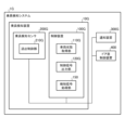
- FIG. 1 is a diagram showing an example of a basic configuration of a control device 100 according to the present disclosure.
- FIG. 2 is a diagram illustrating an example of the configuration of an occupant detection system 1 including a control device 100A according to the first embodiment of the present disclosure.
- FIG. 3 is a flowchart showing an example of processing of the control device 100, 100A according to the first embodiment of the present disclosure.
- FIG. 4 is a diagram illustrating an example of the configuration of an occupant detection system 1B including a control device 100B according to the second embodiment of the present disclosure.
- FIG. 5 is a flowchart showing an example of processing of the control device 100B according to the second embodiment of the present disclosure.
- FIG. 1 is a diagram showing an example of a basic configuration of a control device 100 according to the present disclosure.
- FIG. 2 is a diagram illustrating an example of the configuration of an occupant detection system 1 including a control device 100A according to the first embodiment of the present disclosure.
- FIG. 3 is a flowchart
- FIG. 6 is a diagram showing an example of the configuration of an occupant detection system 1C including a control device 100C according to the third embodiment of the present disclosure.
- FIG. 7 is a flowchart showing an example of processing of the control device 100C according to the third embodiment of the present disclosure.
- FIG. 8 is a diagram showing an example of the configuration of an occupant detection system 1D including a control device 100D according to embodiment 4 of the present disclosure.
- FIG. 9 is a flowchart showing an example of processing of the control device 100D according to the fourth embodiment of the present disclosure.
- FIG. 10 is a flowchart showing a detailed example of a control signal output process in the processing of the control device 100D.
- FIG. 15 is a diagram for explaining the state of electromagnetic wave transmission in response to a control signal from a control device 100E according to the fifth embodiment of the present disclosure.
- FIG. 16 is a diagram for explaining a first example of an electromagnetic wave transmission state in response to a control signal from a control device 100E according to embodiment 5 of the present disclosure.
- FIG. 17 is a diagram for explaining the remaining battery capacity used in the control device 100E according to the fifth embodiment of the present disclosure.
- FIG. 18 is a diagram illustrating a second example of the drive interval of the occupant detection sensor 200E controlled by the control device 100E according to the fifth embodiment of the present disclosure.
- FIG. 19 is a diagram showing an example of the configuration of an occupant detection system 1F including a control device 100F according to embodiment 6 of the present disclosure.
- FIG. 20 is a flowchart showing an example of processing of the control device 100F according to the sixth embodiment of the present disclosure.
- FIG. 21 is a flowchart showing a detailed example of a control signal output process in the control device 100F according to the sixth embodiment of the present disclosure.
- Fig. 22A is a first diagram for explaining an irradiation range of an electromagnetic wave controlled by a control device 100F according to embodiment 6 of the present disclosure.
- Fig. 22B is a second diagram for explaining an irradiation range of an electromagnetic wave controlled by a control device 100F according to embodiment 6 of the present disclosure.
- FIG. 23 is a diagram showing an example of the configuration of an occupant detection system 1G including a control device 100G according to embodiment 7 of the present disclosure.
- FIG. 24 is a flowchart showing an example of processing of the control device 100G according to the seventh embodiment of the present disclosure.
- FIG. 25 is a diagram illustrating a first example of a hardware configuration for realizing the functions of the control devices 100, 100A, 100B, 100C, 100D, 100E, 100F, and 100G in the present disclosure.
- FIG. 26 is a diagram illustrating a second example of a hardware configuration for realizing the functions of the control devices 100, 100A, 100B, 100C, 100D, 100E, 100F, and 100G in the present disclosure.
- Embodiment 1 The first embodiment describes a basic configuration of the present disclosure.
- FIG. 1 is a diagram showing an example of a basic configuration of a control device 100 according to the present disclosure.
- the control device 100 controls an on-board sensor mounted on the vehicle.
- the on-board sensor is, for example, an occupant detection sensor.
- the occupant detection sensor is a sensor that detects an occupant in the vehicle.
- 1 includes a vehicle state acquisition unit 110 and a control signal output unit 120.
- the control device 100 may include, for example, a control unit (not shown), a storage unit (not shown), and a communication unit (not shown).
- a control unit (not shown) receives signals from outside and inside the control device 100 and issues commands related to the operation of the entire control device 100.
- the control unit (not shown) issues commands to start each process in the control device 100, for example.
- the storage unit stores, for example, data used for processing in the control device 100 .
- the communication unit (not shown) transmits and receives data to and from devices external to the control device 100 .
- the vehicle state acquisition unit 110 acquires the vehicle state. Specifically, the vehicle state acquisition unit 110 acquires a vehicle state indicating that the operation of the power source of the vehicle has stopped.
- a power source is something that outputs energy to drive a vehicle, and is, for example, an engine if the vehicle is a gasoline-powered vehicle, a battery if the vehicle is an electric vehicle, or an engine and a battery if the vehicle is a hybrid vehicle.
- the state where the operation of the power source has stopped is a state where the power source is operating and power is being supplied to the on-board sensor, and when the vehicle is in a stopped or parked state, for example, the operation of the power source has stopped and power supply to the on-board sensor has started from the battery (on-board battery) mounted on the vehicle.
- the battery is a typical battery mounted on the vehicle and supplies power to on-board devices, etc.
- the vehicle state acquisition unit 110 acquires, for example, vehicle state information indicating that the operation of the power source has stopped from a vehicle control unit (not shown
- the control signal output unit 120 outputs a control signal using the vehicle state.
- the control signal output unit 120 uses the vehicle state acquired by the vehicle state acquisition unit 110 to output a control signal that operates the occupant detection sensor while changing the operating state of the occupant detection sensor when the operation of the vehicle's power source is stopped.
- the operating state of the occupant detection sensor controlled by the control signal is the operating state of the occupant detection sensor to detect an occupant.
- the operating state of the occupant detection sensor to emit electromagnetic waves is, for example, the drive interval, which is the interval at which the occupant detection sensor is driven to emit electromagnetic waves.
- the output intensity of the electromagnetic waves emitted by the occupant detection sensor when it is driven is driven.
- the number of cycles which is the number of times the electromagnetic waves are repeatedly emitted during the time the occupant detection sensor is driven.
- the control signal output unit 120 acquires the vehicle state from the vehicle state acquisition unit 110 .
- the control signal output unit 120 uses the vehicle state to determine that the operation of the power source of the vehicle has changed to a stopped state.
- control signal output unit 120 determines that the operation of the vehicle's power source has changed to a stopped state using the vehicle state
- the control signal output unit 120 generates and outputs a control signal to operate the occupant detection sensor while gradually changing the operating state of the occupant detection sensor, for example.
- the control signal output unit 120 generates and outputs a control signal to operate the occupant detection sensor while changing the operating state of the occupant detection sensor every elapsed time, for example, as described later.
- control signal output unit 120 generates and outputs a control signal to operate the occupant detection sensor while changing the operating state of the occupant detection sensor in accordance with the remaining battery charge, for example, as described later.
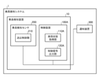
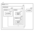
- FIG. 2 is a diagram illustrating an example of the configuration of an occupant detection system 1 including a control device 100A according to the first embodiment of the present disclosure.
- the occupant detection system 1 is a system that, when it detects an occupant in the vehicle while the operation of the power source of the vehicle is stopped, notifies the outside of the vehicle that, for example, the occupant may have been left behind.
- the occupant detection system 1 shown in FIG. 2 includes an occupant detection device 10 and a notification device 300 .
- the occupant detection device 10 detects the presence of an occupant in the vehicle when the operation of the power source of the vehicle is stopped.
- the occupant detection device 10 includes a control device 100A and an occupant detection sensor 200.
- the control device 100A shown in FIG. 2 includes a vehicle state acquisition unit 110A and a control signal output unit 120A. Like the control device 100 already described, the control device 100A may also include, in addition to the above components, a control unit (not shown), a storage unit (not shown), and a communication unit (not shown).
- the vehicle state acquisition unit 110A acquires the vehicle state in the same manner as the vehicle state acquisition unit 110 already described.
- the configuration of the vehicle state acquisition unit 110A is similar to that of the vehicle state acquisition unit 110 already described, and therefore a detailed description thereof will be omitted.
- the control signal output unit 120A outputs a control signal using the vehicle state, similarly to the control signal output unit 120 already described.
- the configuration of the control signal output section 120A is similar to that of the control signal output section 120 already described, and therefore a detailed description thereof will be omitted.
- the occupant detection sensor 200 is mounted on a vehicle and detects an occupant in the vehicle cabin using electromagnetic waves.
- the occupant detection sensor 200 operates by receiving power from a battery mounted on the vehicle, like a general vehicle-mounted device.
- the battery installed in the vehicle is similar to a general vehicle battery.
- the battery supplies power to the vehicle's onboard devices when the operation of the vehicle's power source is stopped.
- the battery stores the regenerative power of the vehicle.
- the occupant detection sensor 200 transmits electromagnetic waves via a transmitting antenna (not shown), receives the electromagnetic waves (also referred to as "reflected waves") reflected by an object (including a living body) to which the electromagnetic waves are irradiated via a receiving antenna (not shown), and outputs a detection signal indicating that an occupant has been detected if the received reflected waves (also referred to as "received waves") indicate the presence of an occupant.
- the occupant detection sensor 200 is, for example, a radar device (a radar device as the occupant detection sensor 200 is also referred to as an "occupant detection radar”).
- the occupant detection radar serving as the occupant detection sensor 200 is, for example, a radar that employs the FMCW method. When the FMCW radar is used as the occupant detection sensor 200, the frequency of the electromagnetic waves to be irradiated can be swept linearly with respect to time.
- the transmission control unit 210 controls the operation state related to the transmission of the occupant detection sensor 200 .
- the output control unit 210 receives a control signal from the control device 100A, it changes the operation state of the occupant detection sensor 200 in accordance with the control signal.
- the notification device 300 notifies that an occupant has been detected.
- the notification device 300 is a device that issues a notification to the outside of the vehicle, and is, for example, a sound output device or a light emitting device. If the notification device 300 is a sound output device, it emits a sound to the outside of the vehicle (the surroundings of the vehicle). If the notification device 300 is a light emitting device, it emits light to the outside of the vehicle (the surroundings of the vehicle).
- the notification device 300 also notifies a notification destination that an occupant has been detected, the notification destination being determined in advance and stored in a storage unit (not shown).
- the notification destination is, for example, a telephone number and an email address.
- the notification destination includes contact information for vehicle-related parties, such as the owner of the vehicle and the driver who was driving the vehicle, or an emergency call destination.
- the emergency call destination may be an external contact, such as a security company, the police, or the fire department.
- the notification device 300 receives a detection signal from the occupant detection sensor 200 or a notification command from the control device 100 in a form that will be described later, and issues a notification in a predetermined and stored form.
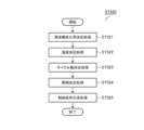
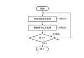
- FIG. 3 is a flowchart showing an example of processing of the control device 100, 100A according to the first embodiment of the present disclosure.
- the control device 100A starts the control process shown in Fig. 3. For example, when the control device 100A receives a signal indicating that the vehicle doors are locked, the control device 100A starts the control process. Also, for example, when the vehicle doors are locked and there is no occupant in the driver's seat, the control device 100A starts the control process.
- the control device 100A first executes a vehicle state acquisition process (step ST110). This process step is also referred to as a vehicle state acquisition step.
- the vehicle state acquisition unit 110A of the control device 100A acquires a vehicle state indicating that the operation of the power source of the vehicle has stopped. Specifically, the vehicle state acquisition unit 110A acquires vehicle state information from, for example, a vehicle control unit (not shown). The vehicle state acquisition unit 110A outputs the acquired vehicle state information to the control signal output unit 120.
- the control device 100A then executes a control signal output process (step ST120).
- This process step is also referred to as a control signal output step.
- the control signal output step the control signal output unit 120A of the control device 100A uses the vehicle state acquired by the vehicle state acquisition unit 110A to output a control signal that operates the occupant detection sensor 200 while changing the operating state of the occupant detection sensor 200 when the operation of the vehicle's power source is stopped.
- the control signal output unit 120A first acquires vehicle state information from the vehicle state acquisition unit 110A.
- the control signal output unit 120A uses the vehicle state information to determine whether the operation of the power source of the vehicle is stopped. When the control signal output unit 120A determines that the operation of the power source of the vehicle is stopped, it generates a control signal that commands the occupant detection sensor 200 to change its operating state.
- the control signal output unit 120A generates a control signal that commands a gradual change from a first operating state stored in advance to a second operating state.
- the control signal output unit 120A stores a first operating state, a second operating state, and a third operating state in advance, and generates a control signal for commanding a change from the first operating state stored in advance to the second operating state, and then a change from the second operating state to the third operating state.
- the first operating state is an operating state for enhancing detection performance for the purpose of rapid occupant detection.
- the second operating state is a state in which the detection performance is lowered and power consumption is reduced compared to the first operating state.
- the third operating state is a state in which the detection performance is lowered and power consumption is further reduced compared to the second operating state.
- this is an operating state in which, compared to the second operating state, the output intensity of the electromagnetic waves is further reduced, the number of cycles of electromagnetic wave transmission is further reduced, the period of electromagnetic wave transmission is further lengthened, and the electromagnetic wave transmission range is intermittently changed.
- control signal output unit 120A may generate a control signal that instructs the operation state to be changed stepwise for each elapsed time, as described later.
- control signal output unit 120A may generate a control signal that instructs the operation state to be changed stepwise according to the remaining battery charge, as described later.
- the control signal output unit 120A outputs the generated control signal to the occupant detection sensor 200.
- the control device 100A determines whether to end the control process (step ST130).
- the control device 100A determines to end the control process when, for example, the time elapsed since the operation of the power source of the vehicle stopped reaches a pre-stored occupant detection time.
- the occupant detection time is set in advance based on, for example, the average remaining battery charge of the battery mounted on the vehicle, and is stored in a storage unit (not shown).
- the control device 100A may determine to end the control process, for example, when triggered by a trigger other than the above.
- step ST130 When the control device 100A determines not to end the control process ("NO" in step ST130), the control device 100A proceeds to step ST110, repeats the process from step ST110, and outputs a control signal by the process of step ST120. When it is determined that the control process is to be ended (“YES" in step ST130), the control device 100A ends the control process.
- control device 100, 100A commands the occupant detection sensor 200 to change the operating state of the occupant detection sensor 200 when the vehicle's power source is stopped, thereby reducing the possibility of problems occurring when detecting an occupant when the vehicle's power source is stopped.
- the control device of the present disclosure is configured as follows. "A control device for an occupant detection sensor that detects an occupant of a vehicle, a vehicle state acquisition unit that acquires a vehicle state indicating that an operation of a power source of the vehicle has stopped; a control signal output unit that uses the vehicle state acquired by the vehicle state acquisition unit to output a control signal for operating the occupant detection sensor while changing an operating state of the occupant detection sensor in a state in which the operation of a power source of the vehicle is stopped; and A control device equipped with As a result, the present disclosure has the effect of providing a control device that can reduce the possibility of problems occurring when detecting an occupant when the vehicle's power source is stopped.
- the control method of the present disclosure is configured as follows. "A control method for a vehicle occupant detection sensor that detects an occupant of a vehicle, a vehicle state acquisition step in which a vehicle state acquisition unit of the control device acquires a vehicle state indicating that an operation of a power source of the vehicle has stopped; a control signal output step in which a control signal output unit of the control device uses the vehicle state acquired by the vehicle state acquisition unit to output a control signal for operating the occupant detection sensor while changing an operating state of the occupant detection sensor in a state in which the operation of a power source of the vehicle is stopped;
- a control method comprising:
- the present disclosure has the effect of providing a control method that can reduce the possibility of problems occurring when detecting an occupant when the vehicle's power source is stopped.
- the occupant detection device of the present disclosure is configured as follows. "An occupant detection sensor that detects an occupant of a vehicle, a vehicle state acquisition unit that acquires a vehicle state indicating that an operation of a power source of the vehicle has stopped; a control signal output unit that uses the vehicle state acquired by the vehicle state acquisition unit to output a control signal for operating the occupant detection sensor while changing an operating state of the occupant detection sensor in a state in which the operation of a power source of the vehicle is stopped; and An occupant detection device equipped with As a result, the present disclosure has the effect of providing an occupant detection device that can reduce the likelihood of problems occurring when detecting an occupant when the vehicle's power source is stopped.
- Embodiment 2 an embodiment will be described in which the operating state of an occupant detection sensor is changed in accordance with the time that has elapsed since the operation of the power source of the vehicle has stopped.
- the description of the configuration already described in the first embodiment may be omitted as appropriate.
- FIG. 4 is a diagram illustrating an example of the configuration of an occupant detection system 1B including a control device 100B according to the second embodiment of the present disclosure.
- An occupant detection system 1B shown in FIG. 4 includes an occupant detection device 10B and a notification device 300B.
- the occupant detection device 10B detects the presence of an occupant in the vehicle when the operation of the power source of the vehicle is stopped.
- the occupant detection device 10B includes a control device 100B and an occupant detection sensor 200B.
- the vehicle state acquisition unit 110B has the same configuration as the vehicle state acquisition units 110 and 110A already described, so a detailed description of this will be omitted.
- the elapsed time acquisition unit 130 acquires the elapsed time.
- the elapsed time is the time that has elapsed since the operation of the power source of the vehicle stopped.
- the elapsed time acquisition unit 130 first acquires the vehicle state acquired by the vehicle state acquisition unit 110B.
- the elapsed time acquisition unit 130 determines that the operation of the power source of the vehicle is stopped, the elapsed time acquisition unit 130 starts measuring time and acquires the elapsed time.
- the elapsed time acquisition unit 130 outputs the acquired elapsed time at every preset time.
- the elapsed time acquisition unit 130 may be configured to directly acquire vehicle state information indicating that the operation of the power source has stopped from a vehicle control unit (not shown).
- the elapsed time acquisition unit 130 may also be configured to acquire the elapsed time from an external timing device (timer) (not shown).
- the control signal output unit 120B uses the vehicle state and the elapsed time to output a control signal that commands the operation of the occupant detection sensor 200B.
- the control signal output unit 120B uses the operating state acquired by the vehicle state acquisition unit 110B and the elapsed time acquired by the elapsed time acquisition unit 130 to output a control signal that operates the occupant detection sensor 200B while changing the operating state of the occupant detection sensor 200B in accordance with the elapsed time when the operation of the vehicle's power source is stopped.
- the control signal output unit 120B acquires the vehicle state from the vehicle state acquisition unit 110B.
- the control signal output section 120B acquires the elapsed time.
- the control signal output unit 120B uses the vehicle state to determine that the operation of the power source of the vehicle has changed to a stopped state.
- the control signal output unit 120B uses the elapsed time to refer to, for example, a database unit (not shown) to obtain the operating state of the occupant detection sensor 200B according to the elapsed time.
- the database unit includes an operation status database that stores in advance elapsed time range information indicating a range of elapsed time and operation status information indicating an operation status in association with each other.
- the control signal output unit 120B generates and outputs a control signal that instructs the operating state of the occupant detection sensor 200B in accordance with the elapsed time, using the operating state of the occupant detection sensor 200B corresponding to the range of elapsed time according to the elapsed time.
- the control signal output unit 120B outputs the control signal generated in this manner to the occupant detection sensor 200B, thereby operating the occupant detection sensor 200B while changing the operating state of the occupant detection sensor 200B in accordance with the elapsed time when the operation of the vehicle's power source is stopped.
- the occupant detection sensor 200B like the occupant detection sensor 200 already described, includes a transmission control unit 210B, and when the transmission control unit 210B receives a control signal from the control device 100B, it changes the operating state of the occupant detection sensor 200B in accordance with the control signal. A detailed description of this will be omitted.
- the notification device 300B issues a notification in a predetermined and stored format based on a detection signal indicating that an occupant has been detected.
- the configuration of the notification device 300B is similar to that of the notification device 300 already described, so a detailed description of this will be omitted.
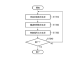
- FIG. 5 is a flowchart showing an example of processing of the control device 100B according to the second embodiment of the present disclosure.
- the control device 100B starts the control process shown in Fig. 5. Like the control device 100A, the control device 100B starts the control process when it receives a signal indicating that the vehicle doors are locked. The control device 100B also starts the control process when, for example, the vehicle doors are locked and there is no occupant in the driver's seat.
- the control device 100B first executes a vehicle state acquisition process (step ST210), which is also referred to as a vehicle state acquisition step.
- a vehicle state acquisition process the vehicle state acquisition unit 110B of the control device 100B, similar to the vehicle state acquisition unit 110A already described, acquires a vehicle state indicating that the operation of the vehicle's power source has stopped, and outputs vehicle state information indicating the vehicle state.
- the control device 100B executes an elapsed time acquisition process (step ST220).
- the elapsed time acquisition unit 130 of the control device 100B first acquires the vehicle state information acquired by the vehicle state acquisition unit 110B.
- the vehicle state information indicates that the operation of the power source of the vehicle is stopped
- the elapsed time acquisition unit 130 starts measuring time and acquires the elapsed time.
- the elapsed time acquisition unit 130 outputs elapsed time information indicating the acquired elapsed time at every preset time.
- the control device 100B then executes a control signal output process (step ST230).
- This process step is also referred to as a control signal output step.
- the control signal output unit 120B of the control device 100B first acquires vehicle state information from the vehicle state acquisition unit 110B.
- the control signal output unit 120B uses the acquired vehicle state information to determine that the operation of the power source of the vehicle has changed to a stopped state. Furthermore, when the elapsed time information is output from the elapsed time acquisition section 130, the control signal output section 120B acquires the elapsed time information.
- the control signal output unit 120B uses the acquired elapsed time information to acquire the operating state of the occupant detection sensor 200B according to the elapsed time indicated by the elapsed time information, for example by referring to a database unit (not shown).
- the control signal output unit 120B generates and outputs a control signal that instructs the operating state of the occupant detection sensor 200B in accordance with the elapsed time, using the operating state of the occupant detection sensor 200B corresponding to the range of elapsed time according to the elapsed time.
- the control device 100B determines whether to end the control process (step ST240).
- the control device 100B like the control device 100A already described, determines to end the control process when, for example, the time elapsed since the operation of the power source of the vehicle stopped reaches the occupant detection time stored in advance.
- the control device 100B may determine to end the control process when, for example, a trigger other than the above is triggered.
- the control device 100B determines not to end the control process ("NO" in step ST240)
- the control device 100B proceeds to step ST210, repeats the process from step ST210, and outputs a control signal by the process of step ST230.
- the control device 100B ends the control process.
- control device 100B can change the operating state for each predetermined range of elapsed time according to the elapsed time. This allows, for example, the occupant detection sensor 200 to be changed to an operating state aimed at rapid occupant detection and an operating state that reduces power consumption.
- the control device of the present disclosure is further configured as follows. "The vehicle further includes an elapsed time acquisition unit that acquires an elapsed time that is the time that has elapsed since the operation of the power source of the vehicle has stopped, The control signal output unit is outputting a control signal for operating the occupant detection sensor while changing the operation state of the occupant detection sensor in accordance with the elapsed time when the operation of the power source of the vehicle is stopped, using the operation state acquired by the vehicle state acquisition unit and the elapsed time acquired by the elapsed time acquisition unit; Control device.”
- the present disclosure provides an advantage of being able to provide a control device that can reduce the possibility of problems occurring when detecting an occupant while the power source of the vehicle is stopped.
- the present disclosure also provides an advantage of being able to provide a control device that maintains the operating state of the occupant detection sensor until a predetermined time has elapsed.
- the present disclosure achieves the same effects as those described above by applying the above configuration to the above control method or the
- Embodiment 3 an embodiment will be described in which the operating state of the occupant detection sensor is changed in accordance with the remaining battery charge after the operation of the power source of the vehicle is stopped.
- the description of the configuration already described in the first embodiment and the configuration already described in the second embodiment may be omitted as appropriate.
- FIG. 6 is a diagram showing an example of the configuration of an occupant detection system 1C including a control device 100C according to the third embodiment of the present disclosure.
- An occupant detection system 1C shown in FIG. 6 includes an occupant detection device 10C and a notification device 300C.
- the occupant detection device 10C detects the presence of an occupant in the vehicle when the operation of the power source of the vehicle is stopped.
- the occupant detection device 10C includes a control device 100C and an occupant detection sensor 200C.
- the control device 100C includes a vehicle state acquisition unit 110C, a control signal output unit 120C, and a battery remaining charge acquisition unit 140. Like the control devices 100, 100A, and 100B already described, the control device 100C may also include, in addition to the above components, a control unit (not shown), a storage unit (not shown), and a communication unit (not shown).
- the vehicle state acquisition unit 110C has a similar configuration to any of the vehicle state acquisition units 110, 110A, and 110B already described, so a detailed description of this will be omitted.
- the battery remaining capacity acquiring unit 140 acquires the battery remaining capacity, which is the remaining capacity of the battery that supplies power to the occupant detection sensor 200C.
- the battery is a typical battery mounted on a vehicle, and supplies power to on-board devices and the like when the operation of the vehicle's power source is stopped.
- the battery remaining amount acquiring unit 140 acquires the vehicle state acquired by the vehicle state acquiring unit 110C, for example.
- the battery remaining amount acquiring unit 140 determines that the operation of the power source of the vehicle is stopped, the battery remaining amount acquiring unit 140 checks the battery remaining amount of the battery and acquires the battery remaining amount.
- the battery remaining amount acquiring unit 140 outputs the acquired battery remaining amount at every preset time.
- the battery remaining capacity acquiring unit 140 may be configured to directly acquire vehicle state information indicating that the operation of the power source has stopped from a vehicle control unit (not shown).
- the battery remaining capacity acquiring unit 140 may also be configured to acquire the battery remaining capacity from an external battery control device (not shown).
- the control signal output unit 120C uses the vehicle state and the remaining battery charge to output a control signal that commands the operation of the occupant detection sensor 200E.
- the control signal output unit 120C uses the vehicle state acquired by the vehicle state acquisition unit 110C and the remaining battery charge acquired by the battery remaining charge acquisition unit 140 to output a control signal that operates the occupant detection sensor 200C while changing the operating state of the occupant detection sensor 200C in accordance with the remaining battery charge when the operation of the vehicle's power source is stopped. Specifically, for example, the control signal output unit 120C acquires the vehicle state from the vehicle state acquisition unit 110C. When the remaining battery charge is output from the remaining battery charge acquisition unit 140, the control signal output unit 120C acquires the remaining battery charge.
- the control signal output unit 120C uses the vehicle state to determine that the operation of the power source of the vehicle is stopped.
- the control signal output unit 120C uses the remaining battery charge to, for example, refer to a database unit (not shown) to obtain the operating state of the occupant detection sensor 200C according to the remaining battery charge.
- the database unit (not shown) includes an operation status database that stores battery remaining capacity range information indicating the range of the battery remaining capacity and operation status information indicating the operation status in advance in association with each other.
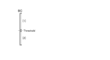
- the operation status database includes, for example, a threshold value that is a boundary value between a range of battery remaining capacity in which the battery is considered to have sufficient power remaining and a range of battery remaining capacity in which the battery is considered to have only a small amount of power remaining.
- the control signal output unit 120C generates and outputs a control signal that instructs the operating state of the occupant detection sensor 200C in accordance with the remaining battery charge, using the operating state of the occupant detection sensor 200C corresponding to the range of remaining battery charge according to the remaining battery charge.
- the control signal output unit 120C outputs the control signal generated in this manner to the occupant detection sensor 200C, thereby operating the occupant detection sensor 200C while changing the operating state of the occupant detection sensor 200C in accordance with the remaining battery charge when the operation of the vehicle's power source is stopped.
- the occupant detection sensor 200C like the occupant detection sensors 200 and 200B already described, includes a transmission control unit 210C, and when the transmission control unit 210C receives a control signal from the control device 100C, it changes the operating state of the occupant detection sensor 200C in accordance with the control signal. A detailed description of this will be omitted.
- the notification device 300C issues a notification in a predetermined and stored format based on a detection signal indicating that an occupant has been detected.
- the configuration of the notification device 300C is similar to that of the notification devices 300 and 300B already described, so a detailed description of this will be omitted.
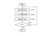
- FIG. 7 is a flowchart showing an example of processing of the control device 100C according to the third embodiment of the present disclosure.
- the control device 100C starts the control process shown in FIG. 7. Like the control devices 100A and 100B, the control device 100C starts the control process, for example, when it receives a signal indicating that the vehicle doors have been locked. The control device 100C also starts the control process, for example, when the vehicle doors are locked and there is no occupant in the driver's seat.
- the control device 100C first executes a vehicle state acquisition process (step ST310), which is also referred to as a vehicle state acquisition step.
- a vehicle state acquisition process the vehicle state acquisition unit 110C of the control device 100C acquires a vehicle state indicating that the operation of the vehicle's power source has stopped, similar to the processing of the vehicle state acquisition units 110, 110A, and B already described, and outputs vehicle state information indicating the vehicle state.
- the control device 100C executes a remaining battery charge acquisition process (step ST320).
- the remaining battery charge acquisition unit 140 of the control device 100C first acquires the vehicle state information acquired by the vehicle state acquisition unit 110C.
- the battery remaining amount acquiring unit 140 acquires the battery remaining amount.
- the battery remaining amount acquiring unit 140 outputs the acquired battery remaining amount information indicating the battery remaining amount at every preset time.
- the control device 100C then executes a control signal output process (step ST330).
- This process step is also referred to as a control signal output step.
- the control signal output unit 120C of the control device 100C first acquires vehicle state information from the vehicle state acquisition unit 110C.
- the control signal output unit 120C uses the acquired vehicle state information to determine that the operation of the power source of the vehicle has changed to a stopped state. Furthermore, when the remaining battery capacity information is output from the remaining battery capacity acquisition unit 140, the control signal output unit 120C acquires the remaining battery capacity information.
- the control device 100C determines whether to end the control process (step ST340).
- the control device 100C determines to end the control process when, for example, the time elapsed since the operation of the power source of the vehicle stopped reaches a pre-stored occupant detection time, similar to the process of the control devices 100A and 100B already described.
- the control device 100C may determine to end the control process when, for example, a trigger other than the above is triggered.
- the control device 100C proceeds to step ST310, repeats the process from step ST310, and outputs a control signal by the process of step ST330.
- the control device 100C ends the control process.
- control device 100C can change the operating state for each predetermined range of remaining battery charge.
- the control device of the present disclosure is further configured as follows. "The vehicle further includes a battery remaining capacity acquisition unit that acquires a remaining battery capacity of a battery that supplies power to the occupant detection sensor, The control signal output unit is using the vehicle state acquired by the vehicle state acquisition unit and the remaining battery charge acquired by the remaining battery charge acquisition unit, outputting a control signal for operating the occupant detection sensor while changing an operation state of the occupant detection sensor in accordance with the remaining battery charge while the operation of the power source of the vehicle is stopped; Control device.”
- the present disclosure provides an advantage of being able to provide a control device that can reduce the possibility of problems occurring when detecting an occupant while the power source of the vehicle is stopped.
- the present disclosure also provides an advantage of being able to provide a control device that can change the operating state of the occupant detection sensor according to the remaining battery charge.
- the present disclosure provides the same effects as those described above by applying the above configuration to the above control method or the above occupant detection device.
- Embodiment 4 a case will be described in which the operating state changed by the control device is the operating interval of an occupant detection sensor.
- the description of embodiment 4 descriptions of the configurations already described in embodiment 1, the configurations already described in embodiment 2, and the configurations already described in embodiment 3 may be omitted as appropriate.
- FIG. 8 is a diagram showing an example of the configuration of an occupant detection system 1D including a control device 100D according to embodiment 4 of the present disclosure.
- An occupant detection system 1D shown in FIG. 8 is obtained by replacing the control device 100A in the occupant detection device 10 of the occupant detection system 1 already described with a control device 100D according to the fourth embodiment of the present disclosure.
- An occupant detection system 1D shown in FIG. 8 includes an occupant detection device 10D and a notification device 300D.
- the occupant detection device 10D detects the presence of an occupant in the vehicle when the operation of the power source of the vehicle is stopped.
- the occupant detection device 10D includes a control device 100D and an occupant detection sensor 200D.
- the control device 100D includes a vehicle state acquisition unit 110D and a control signal output unit 120D. Like the control devices 100, 100A, 100B, and 100C already described, the control device 100D may also include, in addition to the above components, a control unit (not shown), a storage unit (not shown), and a communication unit (not shown).
- the vehicle state acquisition unit 110D has the same configuration as any of the vehicle state acquisition units 110, 110A, 110B, and 110C already described, so a detailed description of this will be omitted.
- the control signal output unit 120D uses the vehicle state to output a control signal that commands the operation of the occupant detection sensor 200D.
- the control signal output unit 120D uses the vehicle state acquired by the vehicle state acquisition unit 110D to output a control signal that operates the occupant detection sensor 200D while changing the operating state of the occupant detection sensor 200D when the operation of the vehicle's power source is stopped.
- the control signal output unit 120D outputs a control signal that commands the occupant detection sensor 200D to change the interval at which the sensor is driven.
- the control signal output unit 120D includes a drive interval determination unit 121.
- the drive interval determination unit 121 determines the drive interval of the occupant detection sensor 200D.
- the drive interval is the interval at which the occupant detection sensor 200D is driven.
- the drive interval is the operation interval indicating, for example, the time between when the occupant detection sensor 200D transmits electromagnetic waves to perform an operation to detect an occupant and the time when the occupant detection sensor 200D performs the operation again.
- the operation interval is indicated, for example, by the time between the start of a previous operation and the start of a subsequent operation.
- the control signal output unit 120D determines that the operation of the power source of the vehicle has stopped, it instructs the drive interval determination unit 121 to determine a drive interval, for example.
- the drive interval determination unit 121 acquires, for example, drive interval information stored in advance, and determines the drive interval to be the drive interval indicated in the acquired drive interval information.
- the control signal output unit 120D receives the drive interval information determined by the drive interval determination unit 121, and outputs a control signal that commands, for example, to gradually change the drive interval from the current drive interval to the drive interval indicated in the drive interval information.
- control device 100D when the drive interval determination unit 121 receives a command, for example, each time it acquires an elapsed time, it refers to a database (this database corresponds to an example of the "operation state database" already described) that contains elapsed time and drive interval information that have been associated and stored in advance, acquires drive interval information corresponding to the elapsed time acquired by the elapsed time acquisition unit 130, and determines the drive interval to be the one indicated in the acquired drive interval information.
- the control signal output unit 120D receives the drive interval information determined by the drive interval determination unit 121, and outputs a control signal that commands a change from the current drive interval to the drive interval indicated by the drive interval information.
- the drive interval determination unit 121 when the drive interval determination unit 121 receives a command, for example, each time the remaining battery capacity is acquired, the drive interval determination unit 121 refers to a database (this database corresponds to an example of the "operating state database" already described) that contains the remaining battery capacity and drive interval information that are associated and stored in advance, acquires drive interval information corresponding to the remaining battery capacity acquired by the battery remaining capacity acquisition unit 140, and determines the drive interval to be the drive interval indicated in the acquired drive interval information.
- the control signal output unit 120D receives the drive interval information determined by the drive interval determination unit 121, and outputs a control signal that commands a change from the current drive interval to the drive interval indicated by the drive interval information.
- the occupant detection sensor 200D includes a transmission control unit 210D, similar to the occupant detection sensors 200, 200B, and 200C already described, and when the transmission control unit 210D receives a control signal from the control device 100D, it changes the operating state of the occupant detection sensor 200D in accordance with the control signal. A detailed description of this will be omitted.
- the notification device 300D issues a notification in a predetermined and stored format based on a detection signal indicating that an occupant has been detected.
- the configuration of the notification device 300D is similar to that of the notification devices 300, 300B, and 300C already described, so a detailed description of this will be omitted.
- FIG. 9 is a flowchart showing an example of processing of the control device 100D according to the fourth embodiment of the present disclosure.
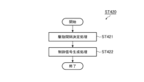
- FIG. 10 is a flowchart showing a detailed example of a control signal output process in the processing of the control device 100D.
- the control device 100D starts the control process shown in FIG. 9. Like the control devices 100A, 100B, and 100C, the control device 100D starts the control process, for example, when it receives a signal indicating that the vehicle doors have been locked. The control device 100D also starts the control process, for example, when the vehicle doors have been locked and there is no occupant in the driver's seat.
- the control device 100D first executes a vehicle state acquisition process (step ST410). This process step is also referred to as a vehicle state acquisition step.
- the vehicle state acquisition unit 110D of the control device 100D acquires a vehicle state indicating that the operation of the vehicle's power source has stopped, similar to the processing of the vehicle state acquisition units 110A, 110B, and 110C already described, and outputs vehicle state information indicating the vehicle state.
- the control device 100D executes a control signal output process (step ST420). This process step is also referred to as a control signal output step.
- the control signal output unit 120D of the control device 100D uses the vehicle state information acquired by the vehicle state acquisition unit 110D to output a control signal that operates the occupant detection sensor 200D while changing the operating state of the occupant detection sensor 200D when the operation of the vehicle's power source is stopped.
- the control signal output unit 120D outputs a control signal that commands the occupant detection sensor 200D to change the interval at which the sensor is driven.
- the control signal output unit 120D instructs the drive interval determination unit 121 to determine a drive interval.
- the drive interval determination unit 121 in the control signal output unit 120D executes the drive interval determination process (step ST421).
- the drive interval determination unit 121 refers to information (corresponding to an example of the "operation state information" already described) stored in advance in a storage unit (not shown) and acquires and determines the drive interval by the occupant detection sensor 200D.
- the drive interval determination unit 121 outputs drive interval information indicating the determined drive interval.
- the control signal output section 120D executes a control signal generation process (step ST422).
- the control signal output unit 120D acquires drive interval information from the drive interval determination unit 121.
- the control signal output unit 120D generates a control signal that instructs operation at the drive interval indicated in the drive interval information.
- the control signal output unit 120D outputs the generated control signal.
- the control signal output section 120D outputs the control signal and ends the control signal output process.
- the control device 100D determines whether to end the control process (step ST430).
- the control device 100D determines to end the control process when, for example, the time elapsed since the operation of the power source of the vehicle stopped reaches a pre-stored occupant detection time, similar to the process of the control devices 100A, 100B, and 100C already described.
- the control device 100D may determine to end the control process when, for example, a trigger other than the above is triggered.
- the control device 100D proceeds to step ST410, repeats the process from step ST410, and outputs a control signal by the process of step ST420.
- the control device 100D ends the control process.
- Fig. 11A is a diagram for explaining an elapsed time used in the control device 100D according to the fourth embodiment of the present disclosure.
- Fig. 11B is a diagram for explaining a first example of a drive interval of the occupant detection sensor 200D controlled by the control device 100D according to the fourth embodiment of the present disclosure.
- the elapsed time acquired by the elapsed time acquisition unit 130 indicates the time elapsed from time A when the power source of the vehicle changes from an on state to an off state, as shown in FIG. 11A.
- the occupant detection sensor 200D performs the occupant detection operation (operation of transmitting electromagnetic waves) at a relatively short drive interval B, and as the elapsed time from time A reaches a predetermined elapsed time, the occupant detection sensor performs the occupant detection operation at a longer drive interval, and then changes to perform the operation at a drive interval C that is longer than the drive interval B.
- a plurality of different time intervals may be determined.
- the control device of the present disclosure is further configured as follows. "The control signal output unit is outputting a control signal to instruct the occupant detection sensor to change an interval at which the occupant detection sensor is driven; Control device.”
- the present disclosure further provides a control device capable of changing the drive interval of the occupant detection sensor when detecting an occupant while the power source of the vehicle is stopped.
- a control device capable of changing the drive interval of the occupant detection sensor when detecting an occupant while the power source of the vehicle is stopped.
- the present disclosure has the effect of providing a control device that can reduce the likelihood of problems such as the vehicle's onboard battery running out, compared to conventional techniques in which the occupant detection sensor continues to perform detection operations at a constant high execution frequency. Furthermore, the present disclosure achieves the same effects as those described above by applying the above configuration to the above control method or the above occupant detection device.
- Embodiment 5 a case will be described in which the operating state changed by the control device is the transmission state of the electromagnetic waves sent out by the occupant detection sensor.
- the operating state changed by the control device is the transmission state of the electromagnetic waves sent out by the occupant detection sensor.
- explanations of the configurations already described in embodiment 1, the configurations already described in embodiment 2, the configurations already described in embodiment 3, and the configurations already described in embodiment 4 may be omitted as appropriate.
- FIG. 12 is a diagram showing an example of the configuration of an occupant detection system 1E including a control device 100E according to embodiment 5 of the present disclosure.
- An occupant detection system 1E shown in FIG. 12 is obtained by replacing the control device 100A in the occupant detection device 10 of the occupant detection system 1 already described with a control device 100E according to embodiment 5 of the present disclosure.
- An occupant detection system 1E shown in FIG. 12 includes an occupant detection device 10E and a notification device 300E.
- the occupant detection device 10E detects the presence of an occupant in the vehicle when the operation of the power source of the vehicle is stopped.
- the occupant detection device 10E includes a control device 100E and an occupant detection sensor 200E.
- the vehicle state acquisition unit 110E has the same configuration as any of the vehicle state acquisition units 110, 110A, 110B, 110C, and 110D already described, so a detailed description of this will be omitted.
- the control signal output unit 120E uses the vehicle state to output a control signal that commands the operation of the occupant detection sensor 200E.
- the control signal output unit 120E uses the vehicle state acquired by the vehicle state acquisition unit 110E to output a control signal that operates the occupant detection sensor 200E while changing the operating state of the occupant detection sensor 200E when the operation of the vehicle's power source is stopped.
- the control signal output unit 120E outputs a control signal that instructs the occupant detection sensor 200E to change the number of cycles, which is the number of times that the occupant detection sensor 200E repeatedly emits electromagnetic waves during the time the occupant detection sensor 200E is driven.
- the control signal output unit 120E outputs a control signal that instructs the occupant detection sensor 200E to change the period at which the occupant detection sensor 200E repeatedly emits electromagnetic waves during the time the occupant detection sensor 200E is driven.
- the control signal output unit 120E outputs a control signal instructing the occupant detection sensor 200E to change two or more of the frequency change rate of the electromagnetic wave emitted by the occupant detection sensor 200E, the output intensity of the electromagnetic wave emitted by the occupant detection sensor 200E, and the number of cycles or period for which the electromagnetic wave is repeatedly emitted by the occupant detection sensor 200E during the time the occupant detection sensor 200E is operated.
- control signal output section 120E shown in FIG. 12 includes a frequency change rate determining section 122, an intensity determining section 123, a number of cycles determining section 124, and a period determining section 125.
- the control signal output unit 120E determines that the operation of the vehicle's power source has changed to a stopped state, it instructs components such as the frequency change rate determination unit 122, the intensity determination unit 123, the cycle number determination unit 124, and the period determination unit 125, which are pre-defined in a memory unit (not shown) or the like (if multiple components are defined, each of the multiple components) to determine a value related to the operating state.
- each component of the control signal output section 120E will be described.
- the frequency change rate determining section 122 determines the frequency change rate of the electromagnetic wave to be transmitted from the occupant detection sensor 200E.
- the frequency change rate is expressed, for example, as the width of frequency fluctuation per unit time ((frequency f2 at end of change - frequency f1 at start of change) / unit time t).
- the frequency change rate determination unit 122 determines and outputs a frequency change rate for each drive time during which the occupant detection sensor 200E performs an occupant detection operation, for example, using a first frequency change rate and a second frequency change rate that are predetermined and stored in a storage unit (not shown). In this case, the frequency change rate determination unit 122 determines and outputs the frequency change rate so that the frequency change rate changes gradually or stepwise from the first frequency change rate to the second frequency change rate for each drive time in a time series.
- the frequency change rate determination unit 122 refers to a database (this database corresponds to an example of the "operational state database" already described) that contains elapsed times and frequency change rates that are associated and stored in advance each time it receives the elapsed time, and acquires and determines the frequency change rate that corresponds to the elapsed time acquired by the elapsed time acquisition unit 130.
- the frequency change rate determination unit 122 refers to a database (this database corresponds to an example of the "operating state database" already described) that contains the remaining battery capacity and the frequency change rate that are previously associated and stored each time the remaining battery capacity is received, and acquires and determines the frequency change rate that corresponds to the remaining battery capacity acquired by the remaining battery capacity acquisition unit 140.
- the control signal output unit 120E generates and outputs a control signal that commands the transmission of electromagnetic waves with the frequency change rate determined by the frequency change rate determination unit 122 each time the frequency change rate is determined by the frequency change rate determination unit 122.
- the strength determining unit 123 determines the output intensity of the electromagnetic wave to be transmitted from the occupant detection sensor 200E.
- the output intensity is expressed in the form of, for example, electric field intensity (V/m), magnetic field intensity (A/m), or power flux density (W/ m2 ), or may simply be expressed in the form of a voltage value, a current value, or a power value for causing the occupant detection sensor 200E to output electromagnetic waves.
- the intensity determination unit 123 determines and outputs the output intensity for each drive time during which the occupant detection sensor 200E emits electromagnetic waves, for example, using a first output intensity and a second output intensity that are predetermined and stored in a storage unit (not shown). In this case, the intensity determination unit 123 determines and outputs the output intensity so that the output intensity changes gradually or stepwise from the first output intensity to the second output intensity in time series in drive time units.
- the intensity determination unit 123 refers to a database (this database corresponds to an example of the "operating state database" already described) that contains elapsed times and output intensities that have been previously associated and stored each time it receives the elapsed time, and acquires and determines the output intensity that corresponds to the elapsed time acquired by the elapsed time acquisition unit 130.
- the intensity determination unit 123 refers to a database (this database corresponds to an example of the "operating status database" already described) that contains the remaining battery capacity and output intensity that are associated and stored in advance each time the remaining battery capacity is received, and acquires and determines the output intensity that corresponds to the remaining battery capacity acquired by the battery remaining capacity acquisition unit 140.
- the control signal output section 120E generates and outputs a control signal that instructs the electromagnetic wave having the output intensity determined by the intensity determination section 123 to be transmitted.
- the cycle number determination unit 124 determines the number of cycles of electromagnetic wave transmission by the occupant detection sensor 200E.
- the number of cycles is the number of times that the occupant detection sensor 200E repeatedly transmits electromagnetic waves during the time that the occupant detection sensor 200E is driven (driving time), in other words, the number of times that the occupant detection operation is performed during each driving time.
- the cycle number determination unit 124 determines and outputs the cycle number for each drive time during which the occupant detection sensor 200E emits electromagnetic waves, for example, using a first cycle number and a second cycle number that are predetermined and stored in a storage unit (not shown). In this case, the cycle number determination unit 124 determines and outputs the cycle number so that the cycle number changes gradually or stepwise from the first cycle number to the second cycle number in time series in drive time units.
- the cycle number determination unit 124 refers to a database (this database corresponds to an example of the "operational state database" already described) that contains elapsed times and cycle numbers that have been previously associated and stored each time it receives an elapsed time, and acquires and determines the number of cycles that corresponds to the elapsed time acquired by the elapsed time acquisition unit 130.
- the cycle number determination unit 124 refers to a database (this database corresponds to an example of the "operating state database" already described) that contains the remaining battery capacity and the number of cycles that are previously associated and stored each time the remaining battery capacity is received, and acquires and determines the number of cycles that corresponds to the remaining battery capacity acquired by the remaining battery capacity acquisition unit 140.
- the control signal output unit 120E generates and outputs a control signal that instructs the cycle number determination unit 124 to emit electromagnetic waves with the number of cycles determined by the cycle number determination unit 124 each time the cycle number is determined by the cycle number determination unit 124.
- the cycle determining unit 125 determines the cycle of electromagnetic wave transmission by the occupant detection sensor 200E.
- the electromagnetic wave transmission cycle is a cycle when the occupant detection sensor 200E repeatedly transmits electromagnetic waves during the time when the occupant detection sensor 200E is driven (driving time), in other words, a time interval between the start of multiple occupant detection operations during each driving time.
- the period determination unit 125 determines a period for each drive time during which the occupant detection sensor 200E emits electromagnetic waves, for example, by using a first period and a second period that are predetermined and stored in a storage unit (not shown). In this case, the period determination unit 125 determines and outputs a period such that the period changes gradually or stepwise from the first period to the second period for each drive time unit in a time series.
- the period determination unit 125 refers to a database (this database corresponds to an example of the "operational state database" already described) that contains elapsed times and periods that are associated and stored in advance each time it receives the elapsed time, and acquires and determines the period that corresponds to the elapsed time acquired by the elapsed time acquisition unit 130.
- the period determination unit 125 refers to a database (this database corresponds to an example of the "operating state database" already described) that contains the remaining battery capacity and the period that are previously associated and stored each time the remaining battery capacity is received, and acquires and determines the period that corresponds to the remaining battery capacity acquired by the remaining battery capacity acquisition unit 140.
- the control signal output unit 120E generates and outputs a control signal that commands the transmission of electromagnetic waves with the period determined by the period determination unit 125 each time the period is determined by the period determination unit 125.
- control signal output unit 120E When the control signal output unit 120E is configured to include all of the frequency change rate determination unit 122, the intensity determination unit 123, the cycle number determination unit 124, and the period determination unit 125, it operates a combination of the frequency change rate determination unit 122, the intensity determination unit 123, the cycle number determination unit 124, and the period determination unit 125 so that the occupant detection sensor 200 can generate electromagnetic waves to be transmitted based on, for example, preset specifications.
- the control signal output unit 120E since the cycle number and the period both determine the frequency of operation for occupant detection, the control signal output unit 120E may be configured to use either the cycle number determination unit 124 or the period determination unit 125.
- control signal output section 120E has been shown to be configured to include all of the frequency change rate determination section 122, the intensity determination section 123, the number of cycles determination section 124, and the period determination section 125, but it may also be configured to include only one of the components of the frequency change rate determination section 122, the intensity determination section 123, the number of cycles determination section 124, and the period determination section 125.
- control signal output unit 120E may be configured to include two or more components, namely, a frequency change rate determination unit 122, an intensity determination unit 123, a cycle number determination unit 124, and a period determination unit 125, to the extent that no contradiction occurs in the operating state.
- the occupant detection sensor 200E like the occupant detection sensors 200, 200B, 200C, and 200D already described, includes a transmission control unit 210E, and when the transmission control unit 210E receives a control signal from the control device 100E, it changes the operating state of the occupant detection sensor 200E in accordance with the control signal. A detailed description of this will be omitted.
- the notification device 300E issues a notification in a predetermined and stored format based on a detection signal indicating that an occupant has been detected.
- the configuration of the notification device 300E is similar to that of the notification devices 300, 300B, 300C, and 300D already described, so a detailed description of this will be omitted.
- FIG. 13 is a flowchart showing an example of processing of the control device 100E according to the fifth embodiment of the present disclosure.
- FIG. 14 is a flowchart showing a detailed example of a control signal output process in the control device 100E according to the fifth embodiment of the present disclosure.
- the control device 100E starts the control process shown in FIG. 13. Like the control devices 100A, 100B, 100C, and 100D, the control device 100E starts the control process, for example, when it receives a signal indicating that the vehicle doors have been locked. The control device 100E also starts the control process, for example, when the vehicle doors have been locked and there is no occupant in the driver's seat.
- the control device 100E first executes a vehicle state acquisition process (step ST510). This process step is also referred to as a vehicle state acquisition step.
- the vehicle state acquisition unit 110E of the control device 100E acquires a vehicle state indicating that the operation of the vehicle's power source has stopped, similar to the processing of the vehicle state acquisition units 110A, 110B, 110C, and 110D already described, and outputs vehicle state information indicating the vehicle state.
- the control device 100E executes a control signal output process (step ST520). This process step is also referred to as a control signal output step.
- the control signal output unit 120E of the control device 100E uses the vehicle state acquired by the vehicle state acquisition unit 110E to output a control signal that operates the occupant detection sensor 200E while changing the operating state of the occupant detection sensor 200E when the operation of the vehicle's power source is stopped.
- the control signal output unit 120E outputs a control signal that commands the occupant detection sensor 200E to change the rate of change of the frequency of the electromagnetic wave transmitted by the occupant detection sensor 200E.
- the control signal output unit 120E outputs a control signal instructing the occupant detection sensor 200E to change two or more of the frequency change rate of the electromagnetic wave emitted by the occupant detection sensor 200E, the output intensity of the electromagnetic wave emitted by the occupant detection sensor 200E, and the number of cycles or period for which the electromagnetic wave is repeatedly emitted by the occupant detection sensor 200E during the time the occupant detection sensor 200E is operated.
- control signal output unit 120E executes the control signal output process shown in FIG. 14, it issues a command to determine an operating state for operating the occupant detection sensor 200E.
- the intensity determination section 123 in the control signal output section 120E executes an intensity determination process (step ST522).
- the intensity determination unit 123 refers to information (operation state information) stored in advance in a storage unit (not shown) or the like, acquires and determines the output intensity.
- the intensity determination unit 123 outputs output intensity information indicating the determined output intensity.
- the cycle number determination section 124 in the control signal output section 120E executes a cycle number determination process (step ST523).
- the cycle number determination unit 124 refers to information (operation state information) stored in advance in a storage unit (not shown) or the like, acquires and determines the number of cycles.
- the cycle number determination unit 124 outputs cycle number information indicating the determined number of cycles.
- the cycle determination section 125 in the control signal output section 120E executes a cycle determination process (step ST524).
- the cycle determination unit 125 refers to information (operation state information) stored in advance in a storage unit (not shown) or the like, acquires and determines the cycle, and outputs cycle information indicating the determined cycle.
- control signal output section 120E executes a control signal generation process (step ST525).
- control signal output unit 120E receives frequency change rate information, output intensity information, cycle number information, and period information, it outputs a control signal that instructs it to emit electromagnetic waves in an operating state according to the received information.
- the control signal output section 120E outputs the control signal and ends the control signal output process.
- the control device 100E determines whether to end the control process (step ST530).
- the control device 100E determines to end the control process when, for example, the time elapsed since the operation of the power source of the vehicle stopped reaches a pre-stored occupant detection time, similar to the process of the control devices 100, 100A, 100B, 100C, and 100D already described.
- the control device 100E may determine to end the control process when, for example, a trigger other than the above is triggered.
- the control device 100E proceeds to step ST510, repeats the process from step ST510, and outputs a control signal by the process of step ST520.
- the control device 100E ends the control process.
- FIG. 15 is a diagram for explaining the state of electromagnetic wave transmission in response to a control signal from a control device 100E according to the fifth embodiment of the present disclosure.
- FIG. 15 is a diagram for explaining the state of electromagnetic wave transmission when the occupant detection sensor 200E is an occupant detection radar that employs FWCW type radar.
- the frequency f of the electromagnetic waves (Tx1, Tx2) emitted by the occupant detection sensor 200E can be swept linearly with respect to time t.
- the detection performance can be made variable.
- the detection performance can be made variable by changing the output intensity of the electromagnetic waves.
- the detection performance in this case refers to performance such as detection distance and distance resolution. It is advantageous to change the detection distance and distance resolution in order to detect an occupant who is not known where he/she is located inside the vehicle cabin, such as on a seat, at the feet, in the luggage compartment, etc. If the control device 100E is controlled based on this viewpoint, the occupant detection sensor 200E can thoroughly search the space inside the vehicle cabin and prevent the occupant from being overlooked.
- FIG. 16 is a diagram for explaining a first example of an electromagnetic wave transmission state in response to a control signal from a control device 100E according to embodiment 5 of the present disclosure.
- 16 shows the relationship between the elapsed time and the amount of power consumption when the operating state (electromagnetic wave transmission state) of the occupant detection sensor 200E is changed.
- the horizontal axis shows the elapsed time t after the power source is stopped, and the vertical axis shows the amount of power consumption P of the occupant detection sensor 200E.
- the operating state a1 is, for example, an operating state in which the output strength of the electromagnetic waves is maximum, the number of cycles of the electromagnetic wave transmission is maximum, and the period of the electromagnetic wave transmission is shortest.
- the operation state b1 has lower detection performance and reduced power consumption than the operation state a1 .
- the operation state b1 is, for example, an operation state in which the output intensity of the electromagnetic waves is lowered, the number of cycles of the electromagnetic wave transmission is reduced, and the period of the electromagnetic wave transmission is lengthened, compared to the operation state a1 .
- the detection performance is further lowered and power consumption is further reduced compared to the operation state b1 .
- the operation state c1 is, for example, an operation state in which the output intensity of the electromagnetic waves is further lowered, the number of cycles of the electromagnetic wave transmission is further reduced, and the period of the electromagnetic wave transmission is further lengthened compared to the operation state b1 .
- FIG. 17 is a diagram for explaining the remaining battery capacity used in the control device 100E according to the fifth embodiment of the present disclosure.
- FIG. 18 is a diagram illustrating a second example of the drive interval of the occupant detection sensor 200E controlled by the control device 100E according to the fifth embodiment of the present disclosure.
- a threshold value corresponding to "Threshold” in the figure
- the operation state is controlled to be a2 .
- control is performed so that the operating state becomes c2 .
- control is performed so that the operation state becomes e2 .
- the remaining battery charge is less than the threshold, and it is better to reduce power consumption. Therefore, in case [2], the operating state is changed for each utilization time period that is a relatively short time interval compared to case [1].
- the operation state is controlled to be a2 .
- control is performed so that the operating state becomes b2 .
- control is performed so that the operating state becomes c2 .
- control is performed so that the operating state becomes d2 .
- control is performed so that the operation state becomes e2 .
- control device 100E By controlling the occupant detection sensor 200E in this manner, the control device 100E enables the occupant detection sensor 200E to quickly detect the presence of an occupant when the vehicle's power source is stopped, and reduces power consumption each time the possibility of an occupant being present decreases, thereby preventing the battery from running out.
- the control device of the present disclosure is further configured as follows. "The control signal output unit is a control signal for instructing the passenger detection sensor to change a frequency change rate of the electromagnetic wave transmitted by the passenger detection sensor; Control device.” As a result, the present disclosure further has the effect of providing a control device that controls an occupant detection sensor capable of emitting electromagnetic waves by sweeping the frequency so as to change the rate of change of the frequency of the electromagnetic waves.
- the present disclosure provides an advantage in that the accuracy of occupant detection using an occupant detection sensor is improved by controlling so as to change the frequency change rate.
- the present disclosure provides the advantage that, by controlling to change the rate of change of frequency, the occupant detection sensor is more likely to detect an occupant early when the operation of the vehicle's power source is stopped.
- the present disclosure has the effect of providing a control device that can reduce the likelihood of problems such as the vehicle's onboard battery running out, compared to conventional techniques in which the occupant detection sensor continues to perform detection operations at a constant high execution frequency. Furthermore, the present disclosure provides the same effects as those described above by applying the above configuration to the above control method or the above occupant detection device.
- the occupant detection device of the present disclosure is further configured as follows. "The control signal output unit is outputting a control signal to instruct the occupant detection sensor to change the output intensity of the electromagnetic wave transmitted by the occupant detection sensor; Control device.”
- the control device advantageously improves the accuracy of occupant detection using the occupant detection sensor by, for example, increasing the output intensity of the electromagnetic wave.
- the control device for example, by changing the output strength of the electromagnetic waves to increase it, has the effect of making it easier for the occupant detection sensor to detect an occupant early when the operation of the vehicle's power source is stopped.
- the control device has an effect of reducing the amount of power consumed by the occupant detection sensor by, for example, changing the output intensity of the electromagnetic waves to a lower level.
- the present disclosure has the effect of providing a control device that can reduce the likelihood of problems such as the vehicle's onboard battery running out, compared to conventional techniques in which the occupant detection sensor continues to perform detection operations at a constant high execution frequency.
- the present disclosure achieves the same effects as those described above by applying the above configuration to the above control method or the above occupant detection device.
- the control device of the present disclosure is further configured as follows. "The control signal output unit is outputting a control signal to instruct the occupant detection sensor to change a cycle number, which is the number of times that the occupant detection sensor repeatedly transmits an electromagnetic wave during a time period in which the occupant detection sensor is driven; Control device.”
- the present disclosure has an effect of providing a control device that is capable of changing the frequency of occupant detection by an occupant detection sensor.
- the control device has an effect of being able to detect an occupant at an early stage by, for example, increasing the number of cycles to increase the frequency of occupant detection by the occupant detection sensor.
- control device has the effect of being able to reduce the amount of power consumed by the occupant detection sensor by, for example, lowering the number of cycles to reduce the frequency of occupant detection by the occupant detection sensor.
- present disclosure has the effect of providing a control device that can reduce the likelihood of problems such as the vehicle's onboard battery running out, compared to conventional techniques in which the occupant detection sensor continues to perform detection operations at a constant high execution frequency.
- present disclosure provides the same effects as those described above by applying the above configuration to the above control method or the above occupant detection device.
- the control device of the present disclosure is further configured as follows. "The control signal output unit is outputting a control signal to instruct the occupant detection sensor to change a period during which the occupant detection sensor repeatedly transmits an electromagnetic wave during a time period during which the occupant detection sensor is driven; Control device.”
- the control device has an effect of providing a control device that is capable of changing the frequency of occupant detection by an occupant detection sensor.
- the control device has an effect of being able to detect an occupant early by, for example, shortening the period to increase the frequency of occupant detection by the occupant detection sensor.
- control device has the effect of being able to reduce the amount of power consumed by the occupant detection sensor, for example, by lengthening the period to reduce the frequency of occupant detection by the occupant detection sensor.
- present disclosure has the effect of providing a control device that can reduce the likelihood of problems such as the vehicle's onboard battery running out, compared to conventional techniques in which the occupant detection sensor continues to perform detection operations at a constant high execution frequency.
- present disclosure provides the same effects as those described above by applying the above configuration to the above control method or the above occupant detection device.
- the control device of the present disclosure is further configured as follows. "The control signal output unit is A rate of change in frequency of the electromagnetic wave transmitted by the occupant detection sensor; The output intensity of the electromagnetic wave transmitted by the occupant detection sensor; and, the number of cycles or periods for which the electromagnetic waves are repeatedly transmitted by the occupant detection sensor during the time the occupant detection sensor is driven; Change two or more of the following: outputting a control signal instructing the Control device.”
- the present disclosure further has an effect of providing a control device that can improve the accuracy of occupant detection by the occupant detection sensor.
- the present disclosure further provides the effect of enabling early detection of an occupant.
- the present disclosure has the effect of providing a control device that can reduce the likelihood of problems such as the vehicle's onboard battery running out, compared to conventional techniques in which the occupant detection sensor continues to perform detection operations at a constant high execution frequency. Furthermore, the present disclosure provides the same effects as those described above by applying the above configuration to the above control method or the above occupant detection device.
- Embodiment 6 In the sixth embodiment, a case will be described in which the object to be controlled by the control device is within the transmission range of the electromagnetic waves transmitted by the occupant detection sensor.
- the explanations of the configurations already described in embodiment 1, the configurations already described in embodiment 2, the configurations already described in embodiment 3, the configurations already described in embodiment 4, and the configurations already described in embodiment 5 may be omitted as appropriate.
- FIG. 19 is a diagram showing an example of the configuration of an occupant detection system 1F including a control device 100F according to embodiment 6 of the present disclosure.
- An occupant detection system 1F shown in FIG. 19 is obtained by replacing the control device 100A in the occupant detection device 10 of the occupant detection system 1 already described with a control device 100F according to the sixth embodiment of the present disclosure.
- An occupant detection system 1F shown in FIG. 19 includes an occupant detection device 10F and a notification device 300F.
- the occupant detection device 10F detects the presence of an occupant in the vehicle when the operation of the power source of the vehicle is stopped.
- the occupant detection device 10F includes a control device 100F and an occupant detection sensor 200F.
- the control device 100F includes a vehicle state acquisition unit 110F and a control signal output unit 120F.
- the control device 100F may also include, for example, a control unit (not shown), a storage unit (not shown), and a communication unit (not shown), similar to the control devices 100, 100A, 100B, 100C, 100D, and 100E already described.
- the vehicle state acquisition unit 110F has a similar configuration to the vehicle state acquisition units 110, 110A, 110B, 110C, 110D, and 110E already described, so a detailed description of this will be omitted.
- the control signal output unit 120F uses the vehicle state to output a control signal that commands the operation of the occupant detection sensor 200F.
- the control signal output unit 120F uses the vehicle state acquired by the vehicle state acquisition unit 110E to output a control signal that operates the occupant detection sensor 200F while changing the operating state of the occupant detection sensor 200F when the operation of the vehicle's power source is stopped.
- the control signal output unit 120F outputs a control signal that instructs the occupant detection sensor 200F to operate while changing the transmission range, which is the range over which the electromagnetic waves are transmitted.
- the occupant detection sensor 200F is configured so that the angle at which the electromagnetic waves are transmitted can be changed.
- it is configured to include a drive mechanism that physically changes the angle of the antenna.
- the drive mechanism is configured to include, for example, a motor or an actuator. Or, for example, it is realized by an array antenna that can change the transmission angle of the electromagnetic waves.
- control signal output section 120F shown in FIG.
- the control signal output unit 120F determines that the operation of the power source of the vehicle has changed to a stopped state, it instructs the throw angle determination unit 126 to determine a value related to the operating state (the throw angle).
- the transmission angle determination unit 126 determines the transmission angle of the electromagnetic wave to the occupant detection sensor 200F.
- the transmission angle indicates the angle of the direction of the transmitted electromagnetic wave, and is expressed in the form of angles on mutually orthogonal planes with the position of the occupant detection sensor 200F as a reference, for example.
- the send angle determination unit 126 determines and outputs a send angle for each drive time during which the occupant detection sensor 200F performs an occupant detection operation, for example, by using a plurality of send angles previously determined and stored in a storage unit (not shown). In this case, the send angle determination unit 126 determines and outputs the send angle such that the send angle changes gradually or stepwise for each drive time in a time series.
- the control signal output unit 120F generates and outputs a control signal that instructs the transmit angle determination unit 126 to transmit electromagnetic waves at the transmit angle determined by the transmit angle determination unit 126.
- the occupant detection sensor 200F like any of the occupant detection sensors 200, 200B, 200C, 200D, and 200E already described, includes a send control unit 210F, and when the send control unit 210F receives a control signal from the control device 100F, it changes the operating state of the occupant detection sensor 200F in accordance with the control signal.
- the transmission control unit 210F also has a function of changing the transmission angle at which the electromagnetic wave is transmitted from the occupant detection sensor 200F.
- the transmission control unit 210F receives a control signal from the control device 100F and controls the drive mechanism or the array antenna in the occupant detection sensor 200F.
- the transmission control unit 210F controls the transmission angle of the electromagnetic wave transmitted by the occupant detection sensor 200F to be changed to the transmission angle determined by the transmission angle determination unit 126. In this way, the transmission control unit 210F of the occupant detection sensor 200F changes the transmission range (the transmission range is also referred to as the "irradiation range") of the electromagnetic wave transmitted from the occupant detection sensor 200F.
- Notification device 300F like notification devices 300, 300B, 300C, 300D, and 300E already described, issues a notification in a predetermined and stored format based on a detection signal indicating that an occupant has been detected.
- the configuration of notification device 300F is similar to that of notification devices 300, 300B, 300C, 300D, and 300E already described, so a detailed description of this will be omitted.
- FIG. 20 is a flowchart showing an example of processing of the control device 100F according to the sixth embodiment of the present disclosure.
- FIG. 21 is a flowchart showing a detailed example of a control signal output process in the control device 100F according to the sixth embodiment of the present disclosure.
- the control device 100F starts the control process shown in FIG. 20. Like the control devices 100, 100A, 100B, 100C, 100D, and 100E, the control device 100F starts the control process, for example, when it receives a signal indicating that the vehicle doors have been locked. The control device 100E also starts the control process, for example, when the vehicle doors have been locked and there is no occupant in the driver's seat.
- the control device 100F first executes a vehicle state acquisition process (step ST610). This process step is also referred to as a vehicle state acquisition step.
- the vehicle state acquisition unit 110F of the control device 100F acquires a vehicle state indicating that the operation of the vehicle's power source has stopped, similar to the processing of the vehicle state acquisition units 110A, 110B, 110C, 110D, and 110E already described, and outputs vehicle state information indicating the vehicle state.
- the control device 100F executes a control signal output process (step ST620). This process step is also referred to as a control signal output step.
- the control signal output unit 120F of the control device 100F uses the vehicle state information acquired by the vehicle state acquisition unit 110F to output a control signal that operates the occupant detection sensor 200F while changing the operating state of the occupant detection sensor 200F when the operation of the vehicle's power source is stopped.
- control signal output unit 120F generates and outputs a control signal that instructs the occupant detection sensor 200F to operate while changing the transmission range over which the sensor transmits electromagnetic waves.
- the send angle determination unit 126 in the control signal output unit 120F executes a send angle determination process in response to the command (step ST621).
- the send angle determination unit 126 acquires and determines a send angle by referring to information (corresponding to an example of the "operation state information" already described) that is predetermined and stored in a storage unit (not shown) or the like.
- the send angle determination unit 126 outputs send angle information indicating the acquired send angle.
- the control signal output section 120F executes a control signal generation process (step ST622). Upon receiving the transmission angle information, the control signal output unit 120F generates and outputs a control signal that commands the transmission of electromagnetic waves in an operating state according to the received transmission angle information. The control signal output section 120F outputs the control signal and ends the control signal output process. The control signal output unit 120F outputs a control signal to a transmission control unit 210F of the occupant detection sensor 200F.
- the control device 100F determines whether to end the control process (step ST630).
- the control device 100F determines to end the control process when, for example, the time elapsed since the operation of the power source of the vehicle stopped reaches a pre-stored occupant detection time, similar to the process of the control devices 100, 100A, 100B, 100C, 100D, and 100E already described.
- the control device 100F may determine to end the control process when, for example, a trigger other than the above is triggered.
- the control device 100F proceeds to step ST610, repeats the process from step ST610, and outputs a control signal by the process of step ST620.
- the control device 100F ends the control process.
- Fig. 22A is a first diagram for explaining an irradiation range of an electromagnetic wave controlled by a control device 100F according to embodiment 6 of the present disclosure.
- Fig. 22B is a second diagram for explaining an irradiation range of an electromagnetic wave controlled by a control device 100F according to embodiment 6 of the present disclosure.
- the direction in which electromagnetic waves are emitted is limited to angles such as 100° in the horizontal direction and 80° in the vertical direction.
- the control device 100F controls the occupant detection sensor 200F so as to change the transmission angle.
- Fig. 22A shows the state of the occupant detection sensor 200F when it is attached to a vehicle and viewed in the direction of gravity.
- the control device 100F changes the direction of electromagnetic waves emitted from the occupant detection sensor 200F so that it rotates in the vehicle width direction W (the vehicle width direction corresponds to the horizontal direction) around the occupant detection sensor 200F as shown in Fig. 22A. This enables the occupant detection sensor 200F to thoroughly search the area up to the vehicle door side.
- Fig. 22B shows the state of the occupant detection sensor 200F mounted on the vehicle as viewed from the side.
- the control device 100F changes the direction of electromagnetic waves emitted by the occupant detection sensor 200F so that it rotates in the vehicle height direction H (the vehicle height direction corresponds to the vertical direction) around the occupant detection sensor 200F as shown in Fig. 22B. This enables the occupant detection sensor 200F to thoroughly search under the seat (the feet). This is because small children, in particular, may fall under the seat and may make unexpected movements, and searching down to the feet is effective for occupant detection.
- the control device of the present disclosure is further configured as follows. "The control signal output unit is outputting a control signal to instruct the occupant detection sensor to operate while changing a transmission range, which is a range in which the occupant detection sensor transmits electromagnetic waves; Control device.”
- the present disclosure further has the effect of providing a control device that makes it possible to detect an occupant left behind in a vehicle at an early stage and reduces the risk of missing detection of the occupant.
- the present disclosure has the effect of providing a control device that can reduce the likelihood of problems such as the vehicle's onboard battery running out, compared to conventional techniques in which the occupant detection sensor continues to perform detection operations at a constant high execution frequency.
- the present disclosure provides the same effects as those described above by applying the above configuration to the above control method or the above occupant detection device.
- Embodiment 7 In the seventh embodiment, a case will be described in which the control device issues a command to open the doors and windows of the vehicle based on the detection result by the occupant detection sensor.
- the explanations of the configurations already described in embodiment 1, the configurations already described in embodiment 2, the configurations already described in embodiment 3, the configurations already described in embodiment 4, the configurations already described in embodiment 5, and the configurations already described in embodiment 6 may be omitted as appropriate.
- FIG. 23 is a diagram showing an example of the configuration of an occupant detection system 1G including a control device 100G according to embodiment 7 of the present disclosure.
- the occupant detection system 1G shown in Figure 23 replaces the control device 100A in the occupant detection device 10 of the occupant detection system 1 already described with a control device 100G relating to embodiment 7 of the present disclosure, and additionally includes a door window control device 400.
- An occupant detection system 1G shown in FIG. 23 includes an occupant detection device 10G, a notification device 300G, and a door window control device 400.
- the occupant detection device 10G detects the presence of an occupant in the vehicle when the operation of the power source of the vehicle is stopped.
- the occupant detection device 10G includes a control device 100G and an occupant detection sensor 200G.
- the control device 100G includes a vehicle state acquisition unit 110G, a control signal output unit 120G, and a detection signal processing unit 150.
- the control device 100G may also include, for example, a control unit (not shown), a storage unit (not shown), and a communication unit (not shown), similar to the control devices 100, 100A, 100B, 100C, 100D, 100E, and 100F already described.
- the vehicle state acquisition unit 110G has the same configuration as any of the vehicle state acquisition units 110, 110A, 110B, 110C, 110D, 110E, and 110F already described, so a detailed description of this will be omitted.
- the control signal output unit 120G has the same configuration as any of the control signal output units 120, 120A, 120B, 120C, 120D, 120E, and 120F already described, so a detailed description of this will be omitted.
- the detection signal processor 150 uses the detection signal to notify the driver that an occupant has been detected and to control the doors or windows of the vehicle.
- the detection signal processing unit 150 receives a detection signal indicating that an occupant has been detected from the occupant detection sensor 200G, it outputs a notification command to notify the outside of the vehicle, and also outputs a control command to unlock the vehicle doors, a control command to open the vehicle doors, or a control command to open the vehicle windows.
- the detection signal processor 150 acquires the detection signal output by the occupant detection sensor 200G, and when it determines that an occupant is present in the vehicle, generates a notification command signal indicating a command to notify the outside of the vehicle of the presence of the occupant.
- the notification command signal indicates, for example, a command to notify by sound output, light emission, or communication.
- the detection signal processor 150 acquires the detection signal output by the occupant detection sensor 200G, and when it determines that an occupant is present in the vehicle, generates a control command signal for instructing control of the vehicle doors or windows.
- the control command signal indicates, for example, a control command for unlocking the vehicle doors, a control command for opening the vehicle doors, or a command for opening the vehicle windows.
- the detection signal processing unit 150 may output a notification command and a control command when it determines that the vehicle's interior temperature exceeds a threshold value, in addition to determining that an occupant is present in the vehicle.
- the vehicle's interior temperature can be determined by using a signal from a temperature sensor (not shown) or the like.
- the occupant detection sensor 200G when the occupant detection sensor 200G receives a control signal from the control device 100G, the occupant detection sensor 200G changes the operating state of the occupant detection sensor 200G in accordance with the control signal.
- the occupant detection sensor 200G includes a transmission control section 210G.
- the sending control unit 210G has the same function as any one of the sending control units 210, 210B, 210C, 210D, 210E, and 210F already described.
- the notification device 300G notifies that an occupant has been detected.
- the notification device 300G is a device that issues a notification to the outside of the vehicle, and is, for example, a sound output device or a light emitting device. If the notification device 300G is a sound output device, it emits a sound to the outside of the vehicle (the surroundings of the vehicle). If the notification device 300G is a light emitting device, it emits light to the outside of the vehicle (the surroundings of the vehicle).
- the notification device 300G also notifies a notification destination that an occupant has been detected, the notification destination being determined in advance and stored in a storage unit (not shown).
- the notification destination is, for example, a telephone number and an email address.
- the notification destination includes contact information for vehicle-related parties, such as the owner of the vehicle and the driver who was driving the vehicle, or an emergency call destination.
- the emergency call destination may be an external contact, such as a security company, the police, or the fire department.
- the notification device 300G receives a detection signal output from the occupant detection sensor 200G or a notification command output from the control device 100G, and issues a notification in a predetermined and stored format.
- the door window control device 400 controls the locking and unlocking of the vehicle doors.
- the door window control device 400 receives a control command output from the control device 100G and unlocks the vehicle doors.
- the door window control device 400 controls a vehicle door opening/closing device to open and close the door.
- the door window control device 400 receives a control command output from the control device 100G and opens the vehicle door.
- the door window control device 400 controls a vehicle window opening/closing device to open and close the window.
- the door window control device 400 receives a control command output from the control device 100G and opens the vehicle window.
- FIG. 24 is a flowchart showing an example of processing of the control device 100G according to the seventh embodiment of the present disclosure.
- the control device 100G starts processing the detection signal.
- the detection signal processing is a process that uses the detection signal to notify the driver that an occupant has been detected and to control the vehicle doors or windows.
- the control device 100G determines whether or not a detection signal has been received (step ST710).
- the detection signal processing unit 150 in the control device 100G acquires the detection signal output from the occupant detection sensor 200, it determines that the detection signal has been received.
- the control device 100G determines whether the condition is satisfied (step ST720).
- the detection signal processing unit 150 in the control device 100G first determines that the detection signal indicates that an occupant has been detected.
- the detection signal processing unit 150 acquires a signal from a temperature sensor (not shown).
- the detection signal processing unit 150 uses the signal from the temperature sensor to determine that the vehicle's interior temperature has exceeded a threshold value.
- the detection signal processing unit 150 determines that an occupant is present in the vehicle and that the vehicle's interior temperature has exceeded a threshold value, it outputs a notification command and a control command.
- the control device 100G executes a notification process (step ST730).
- the detection signal processor 150 outputs a notification command to the notification device 300 .
- the control device 100G executes a door window control process (step ST740).
- a control command is output to the door window control device 400 .
- Control device 100G determines whether to end the detection signal processing (step ST750).
- the control device 100G determines to end the control process when, for example, the time elapsed since the operation of the power source of the vehicle stopped reaches a pre-stored occupant detection time, similar to the process of the control devices 100A, 100B, 100C, 100D, 100E, and 100F already described.
- the control device 100G may determine to end the control process when, for example, a trigger other than the above is triggered.
- the control device 100G proceeds to step ST710 and repeats the process from step ST710.
- the control device 100G ends the detection signal processing.
- the control device of the present disclosure is further configured as follows. "Upon receiving a detection signal indicating that an occupant has been detected from the occupant detection sensor, outputting a notification command to notify an outside of the vehicle; outputting a control command to unlock a door of the vehicle, a control command to open a door of the vehicle, or a control command to open a window of the vehicle; A detection signal processing unit is further provided. Control device.” As a result, the present disclosure further has the effect of providing a control device that, when an occupant has been left behind in a vehicle, notifies the outside of the vehicle that an occupant has been left behind and assists in getting the occupant out of the vehicle. Furthermore, the present disclosure provides the same effects as those described above by applying the above configuration to the above control method or the above occupant detection device.
- FIG. 25 is a diagram illustrating a first example of a hardware configuration for realizing the functions of the control devices 100, 100A, 100B, 100C, 100D, 100E, 100F, and 100G in this disclosure.
- FIG. 26 is a diagram illustrating a second example of a hardware configuration for realizing the functions of the control devices 100, 100A, 100B, 100C, 100D, 100E, 100F, and 100G in the present disclosure.
- Control devices 100, 100A, 100B, 100C, 100D, 100E, 100F, and 100G of the present disclosure are realized by hardware such as that shown in FIG. 25 or FIG. 26.
- each of the control devices 100, 100A, 100B, 100C, 100D, 100E, 100F, and 100G is composed of, for example, a processor 10001, a memory 10002, and a communication circuit 10004.
- the processor 10001 and the memory 10002 are installed in, for example, a computer.
- the memory 10002 stores programs for causing the computer to function as a vehicle state acquisition unit 110, a control signal output unit 120, 120A, 120B, 120C, 120D, 120E, 120F, 120G, a drive interval determination unit 121, a frequency change rate determination unit 122, a strength determination unit 123, a cycle number determination unit 124, a period determination unit 125, a transmission angle determination unit 126, an elapsed time acquisition unit 130, a remaining battery charge acquisition unit 140, a detection signal processing unit 150, and a control unit not shown.
- processor 10001 reading and executing the program stored in memory 10002, the functions of vehicle state acquisition unit 110, control signal output units 120, 120A, 120B, 120C, 120D, 120E, 120F, 120G, drive interval determination unit 121, frequency change rate determination unit 122, strength determination unit 123, cycle number determination unit 124, period determination unit 125, transmission angle determination unit 126, elapsed time acquisition unit 130, battery remaining capacity acquisition unit 140, detection signal processing unit 150, and a control unit not shown are realized.
- a storage unit (not shown) is realized by the memory 10002 or another memory (not shown).
- a database (not shown) in the description is realized by the memory 10002 or another memory (not shown).
- the communication circuit 10004 realizes a communication unit (not shown).
- the processor 10001 is, for example, a central processing unit (CPU), a graphics processing unit (GPU), a microprocessor, a microcontroller, or a digital signal processor (DSP).
- the memory 10002 may be a non-volatile or volatile semiconductor memory such as a RAM (Random Access Memory), a ROM (Read Only Memory), an EPROM (Erasable Programmable ROM), an EEPROM (Electrically Erasable Programmable Read Only Memory), or a flash memory, or a magnetic disk such as a hard disk or a flexible disk, or an optical disk such as a CD (Compact Disc) or a DVD (Digital Versatile Disc), or a magneto-optical disk.
- RAM Random Access Memory
- ROM Read Only Memory
- EPROM Erasable Programmable ROM
- EEPROM Electrically Erasable Programmable Read Only Memory
- flash memory or a magnetic disk such as a hard disk or a flexible disk, or an optical disk such as a CD (Com
- the processor 10001 and the memory 10002 or the communication circuit 10004 are connected in a state in which they can transmit data to each other.
- the processor 10001, the memory 10002, and the communication circuit 10004 are also connected in a state in which they can transmit data to other hardware via the input/output interface 10003.
- the functions of the vehicle state acquisition unit 110, the control signal output units 120, 120A, 120B, 120C, 120D, 120E, 120F, 120G, the drive interval determination unit 121, the frequency change rate determination unit 122, the intensity determination unit 123, the cycle number determination unit 124, the period determination unit 125, the transmission angle determination unit 126, the elapsed time acquisition unit 130, the remaining battery charge acquisition unit 140, the detection signal processing unit 150, and a control unit (not shown) may be realized by a dedicated processing circuit 20001 as shown in FIG. 26.
- the communication circuit 10004 realizes a communication unit (not shown).
- the processing circuit 20001 may be, for example, a single circuit, a composite circuit, a programmed processor, a parallel programmed processor, an ASIC (Application Specific Integrated Circuit), a PLD (Programmable Logic Device), an FPGA (Field-Programmable Gate Array), a SoC (System-on-a-Chip), or a system LSI (Large-Scale Integration).
- the memory 20002 or another memory not shown in the figure realizes a storage unit not shown in the figure.
- the memory 20002 may be a non-volatile or volatile semiconductor memory such as a RAM (Random Access Memory), a ROM (Read Only Memory), an EPROM (Erasable Programmable ROM), an EEPROM (Electrically Erasable Programmable Read Only Memory), or a flash memory, or a magnetic disk such as a hard disk or a flexible disk, or an optical disk such as a CD (Compact Disc) or a DVD (Digital Versatile Disc), or a magneto-optical disk.
- the communication circuit 20004 realizes a communication unit (not shown).
- the processing circuit 20001 and the memory 20002 or the communication circuit 20004 are connected in a state in which they can transmit data to each other.
- the processing circuit 20001, the memory 20002, and the communication circuit 20004 are connected in a state in which they can transmit data to other hardware via the input/output interface 20003.
- the vehicle state acquisition unit 110 may be realized by the processor 10001 and the memory 10002, and the remaining functions may be realized by the processing circuit 20001.
- the technology disclosed herein can reduce the likelihood of problems occurring when detecting occupants when the vehicle's power source is stopped, and is therefore suitable for use in technology related to a control device, control method, or occupant detection device that controls an occupant detection device that detects vehicle occupants.
Landscapes
- Engineering & Computer Science (AREA)
- Mechanical Engineering (AREA)
- Electric Propulsion And Braking For Vehicles (AREA)
Abstract
制御装置(100)は、車両の乗員を検知する乗員検知センサの制御装置であって、車両の動力源の動作が停止したことを示す車両状態を取得する車両状態取得部(110)と、車両状態取得部により取得された車両状態を用いて、車両の動力源の動作が停止した状態において乗員検知センサの動作状態を変化させながら乗員検知センサを動作させる制御信号を出力する制御信号出力部(120)と、を備えた。
Description
本開示技術は、車両の乗員を検知する乗員検知センサの制御技術に関する。
乗員検知センサの中には、車両が停車している場合に乗員を検知するものがある。一般に、乗員検知センサを含む車載装置は、車両のエンジンといった動力源が停止している状態においては、車両に搭載されたバッテリから電力供給を受けて動作する。
特許文献1には、車両が停車している場合に乗員を検出する検出動作を実行させる車両乗員検出装置(「乗員検知センサ」に相当)が開示されている。
具体的には、特許文献1の車両乗員検出装置は、車両のエンジンが停止している状態において、車両と保護者が所持する携帯端末との相対距離が例えば5mより長くなった場合に一定の高い実行頻度で車両内における子供の存在有無を検出する検出動作を実行する。この際、車両乗員検出装置は、車載バッテリからの電力供給を受けて動作する(特許文献1における特に段落[0021]、[0022]、[0025]、[0027]、および、[0028]等参照)。
特許文献1には、車両が停車している場合に乗員を検出する検出動作を実行させる車両乗員検出装置(「乗員検知センサ」に相当)が開示されている。
具体的には、特許文献1の車両乗員検出装置は、車両のエンジンが停止している状態において、車両と保護者が所持する携帯端末との相対距離が例えば5mより長くなった場合に一定の高い実行頻度で車両内における子供の存在有無を検出する検出動作を実行する。この際、車両乗員検出装置は、車載バッテリからの電力供給を受けて動作する(特許文献1における特に段落[0021]、[0022]、[0025]、[0027]、および、[0028]等参照)。
しかしながら、特許文献1に開示される技術では、一定の高い実行頻度で検知動作し続けてしまう場合があるため、仮に車両の動力源が停止している状態において乗員を検知する場合にはバッテリが上がってしまうといった問題が生じる可能性が高いという課題がある。
本開示は、上記課題を解決するもので、車両の動力源が停止している状態において乗員を検知する場合の問題が生じる可能性を低くすることを目的とする。
本開示の制御装置は、
車両の乗員を検知する乗員検知センサの制御装置であって、
前記車両の動力源の動作が停止したことを示す車両状態を取得する車両状態取得部と、
前記車両状態取得部により取得された車両状態を用いて、前記車両の動力源の動作が停止した状態において前記乗員検知センサの動作状態を変化させながら検知動作させる制御信号を出力する制御信号出力部と、
を備えた。
車両の乗員を検知する乗員検知センサの制御装置であって、
前記車両の動力源の動作が停止したことを示す車両状態を取得する車両状態取得部と、
前記車両状態取得部により取得された車両状態を用いて、前記車両の動力源の動作が停止した状態において前記乗員検知センサの動作状態を変化させながら検知動作させる制御信号を出力する制御信号出力部と、
を備えた。
本開示によれば、車両の動力源が停止している状態において乗員を検知する場合の問題点が生じる可能性を低くすることができる、という効果を奏する。
実施の形態1.
実施の形態1は、本開示の基本的な構成を説明する。
実施の形態1は、本開示の基本的な構成を説明する。
図1は、本開示の制御装置100の基本的な構成の一例を示す図である。
制御装置100は、車両に搭載された車載センサを制御する。車載センサは、例えば乗員検知センサである。
乗員検知センサは、車両の乗員を検知するセンサである。
図1に示す制御装置100は、車両状態取得部110および制御信号出力部120を含み構成されている。制御装置100は、上記の構成部以外に、例えば図示しない制御部、図示しない記憶部および図示しない通信部を含んで構成されていてもよい。
図示しない制御部は、制御装置100の外部および制御装置100の内部からの信号を受けて制御装置100全体の動作に係る指令を行う。図示しない制御部は、例えば制御装置100における各処理を開始させる指令を行う。
図示しない記憶部は、例えば、制御装置100において処理に用いるデータを記憶する。
図示しない通信部は、制御装置100の外部に存在する装置との間でデータの送受信を行う。
制御装置100は、車両に搭載された車載センサを制御する。車載センサは、例えば乗員検知センサである。
乗員検知センサは、車両の乗員を検知するセンサである。
図1に示す制御装置100は、車両状態取得部110および制御信号出力部120を含み構成されている。制御装置100は、上記の構成部以外に、例えば図示しない制御部、図示しない記憶部および図示しない通信部を含んで構成されていてもよい。
図示しない制御部は、制御装置100の外部および制御装置100の内部からの信号を受けて制御装置100全体の動作に係る指令を行う。図示しない制御部は、例えば制御装置100における各処理を開始させる指令を行う。
図示しない記憶部は、例えば、制御装置100において処理に用いるデータを記憶する。
図示しない通信部は、制御装置100の外部に存在する装置との間でデータの送受信を行う。
車両状態取得部110は、車両状態を取得する。
具体的には、車両状態取得部110は、車両の動力源の動作が停止したことを示す車両状態を取得する。
動力源は、車両を駆動させるエネルギーを出力するものであり、例えば車両がガソリン車である場合はエンジンであり、また、例えば車両が電気自動車である場合はバッテリであり、また、例えば車両がハイブリッド車である場合はエンジンおよびバッテリである。
動力源の動作が停止した状態は、動力源が動作していることにより車載センサに電力供給されている状態から、例えば車両の状態が停車状態、および、駐車状態といった状態において、動力源の動作が停止したことにより車両に搭載されたバッテリ(車載バッテリ)から車載センサに電力供給が開始された状態である。バッテリは、車両に搭載されている一般的なバッテリであり、車載機器等に電力を供給する。
車両状態取得部110は、例えば、図示しない車両制御部から動力源の動作が停止したことを示す車両状態情報を取得する。
具体的には、車両状態取得部110は、車両の動力源の動作が停止したことを示す車両状態を取得する。
動力源は、車両を駆動させるエネルギーを出力するものであり、例えば車両がガソリン車である場合はエンジンであり、また、例えば車両が電気自動車である場合はバッテリであり、また、例えば車両がハイブリッド車である場合はエンジンおよびバッテリである。
動力源の動作が停止した状態は、動力源が動作していることにより車載センサに電力供給されている状態から、例えば車両の状態が停車状態、および、駐車状態といった状態において、動力源の動作が停止したことにより車両に搭載されたバッテリ(車載バッテリ)から車載センサに電力供給が開始された状態である。バッテリは、車両に搭載されている一般的なバッテリであり、車載機器等に電力を供給する。
車両状態取得部110は、例えば、図示しない車両制御部から動力源の動作が停止したことを示す車両状態情報を取得する。
制御信号出力部120は、車両状態を用いて、制御信号を出力する。
制御信号出力部120は、車両状態取得部110により取得された車両状態を用いて、車両の動力源の動作が停止した状態において乗員検知センサの動作状態を変化させながら乗員検知センサを動作させる制御信号を出力する。
制御信号により制御される乗員検知センサの動作状態は、乗員検知センサが乗員を検知しようとする動作の状態である。具体的には、乗員検知センサが電磁波を送出するものである場合、乗員検知センサが電磁波を送出する動作の状態であり、例えば、乗員検知センサが駆動して電磁波を送出する間隔である駆動間隔である。また、例えば、乗員検知センサが駆動して送出する電磁波の周波数変化率である。また、例えば、乗員検知センサが駆動して送出する電磁波の出力強度である。また、例えば、乗員検知センサが駆動する時間において電磁波を繰り返し送出する回数であるサイクル数である。また、例えば、乗員検知センサが駆動する時間において乗員検知センサが電磁波を繰り返し送出する周期である。
制御信号出力部120は、車両状態取得部110から車両状態を取得する。
制御信号出力部120は、車両状態を用いて車両の動力源の動作が停止した状態に変化したことを判定する。
制御信号出力部120は、車両状態を用いて車両の動力源の動作が停止した状態に変化したことを判定すると、例えば、乗員検知センサの動作状態を徐々に変化させながら乗員検知センサを動作させるように制御信号を生成して出力する。また、制御信号出力部120は、例えば、後に説明するように、乗員検知センサの動作状態を経過時間ごとに変化させながら乗員検知センサを動作させるように制御信号を生成して出力する。また、制御信号出力部120は、例えば、後に説明するように、乗員検知センサの動作状態をバッテリ残量に応じて変化させながら乗員検知センサを動作させるように制御信号を生成して出力する。
制御信号出力部120は、車両状態取得部110により取得された車両状態を用いて、車両の動力源の動作が停止した状態において乗員検知センサの動作状態を変化させながら乗員検知センサを動作させる制御信号を出力する。
制御信号により制御される乗員検知センサの動作状態は、乗員検知センサが乗員を検知しようとする動作の状態である。具体的には、乗員検知センサが電磁波を送出するものである場合、乗員検知センサが電磁波を送出する動作の状態であり、例えば、乗員検知センサが駆動して電磁波を送出する間隔である駆動間隔である。また、例えば、乗員検知センサが駆動して送出する電磁波の周波数変化率である。また、例えば、乗員検知センサが駆動して送出する電磁波の出力強度である。また、例えば、乗員検知センサが駆動する時間において電磁波を繰り返し送出する回数であるサイクル数である。また、例えば、乗員検知センサが駆動する時間において乗員検知センサが電磁波を繰り返し送出する周期である。
制御信号出力部120は、車両状態取得部110から車両状態を取得する。
制御信号出力部120は、車両状態を用いて車両の動力源の動作が停止した状態に変化したことを判定する。
制御信号出力部120は、車両状態を用いて車両の動力源の動作が停止した状態に変化したことを判定すると、例えば、乗員検知センサの動作状態を徐々に変化させながら乗員検知センサを動作させるように制御信号を生成して出力する。また、制御信号出力部120は、例えば、後に説明するように、乗員検知センサの動作状態を経過時間ごとに変化させながら乗員検知センサを動作させるように制御信号を生成して出力する。また、制御信号出力部120は、例えば、後に説明するように、乗員検知センサの動作状態をバッテリ残量に応じて変化させながら乗員検知センサを動作させるように制御信号を生成して出力する。
本開示の制御装置100を乗員検知システムに適用した場合の構成例について説明する。
図2は、本開示の実施の形態1に係る制御装置100Aを含む乗員検知システム1の構成の一例を示す図である。
乗員検知システム1は、車両の動力源の動作が停止した状態において車両の乗員を検知した場合、例えば置き去りの可能性がある旨を車両の外部へ通知するシステムである。
図2に示す乗員検知システム1は、乗員検知装置10および通知装置300を含み構成されている。
図2は、本開示の実施の形態1に係る制御装置100Aを含む乗員検知システム1の構成の一例を示す図である。
乗員検知システム1は、車両の動力源の動作が停止した状態において車両の乗員を検知した場合、例えば置き去りの可能性がある旨を車両の外部へ通知するシステムである。
図2に示す乗員検知システム1は、乗員検知装置10および通知装置300を含み構成されている。
乗員検知装置10は、車両の動力源の動作が停止した状態において車両の乗員を検知する。
乗員検知装置10は、制御装置100Aおよび乗員検知センサ200を含み構成されている。
乗員検知装置10は、制御装置100Aおよび乗員検知センサ200を含み構成されている。
図2に示す制御装置100Aは、車両状態取得部110Aおよび制御信号出力部120Aを含み構成されている。制御装置100Aは、既に説明した制御装置100と同様に、上記の構成部以外に、例えば図示しない制御部、図示しない記憶部および図示しない通信部を含んで構成されていてもよい。
車両状態取得部110Aは、既に説明した車両状態取得部110と同様に、車両状態を取得する。
車両状態取得部110Aの構成は、既に説明した車両状態取得部110と同様であるため、この詳細な説明は省略する。
車両状態取得部110Aの構成は、既に説明した車両状態取得部110と同様であるため、この詳細な説明は省略する。
制御信号出力部120Aは、既に説明した制御信号出力部120と同様に、車両状態を用いて、制御信号を出力する。
制御信号出力部120Aの構成は、既に説明した制御信号出力部120と同様あるため、この詳細な説明は省略する。
制御信号出力部120Aの構成は、既に説明した制御信号出力部120と同様あるため、この詳細な説明は省略する。
乗員検知センサ200は、車両に搭載されており、電磁波を用いて車室内の乗員を検知する。乗員検知センサ200は、車両の動力源の動作が停止した状態においては、一般的な車載機器と同様に、車両に搭載されたバッテリから電力を受けて動作する。
車両に搭載されたバッテリは、一般的な車載バッテリと同様である。バッテリは、例えば、車両の動力源の動作が停止した状態において車載機器に電力を供給する。また、バッテリは、車両が回生電力を蓄積できる機能を有する場合、車両における回生電力を蓄積する。
乗員検知センサ200は、例えば、図示しない送信アンテナを介して電磁波を送出し、電磁波が照射された物体(物体は生体を含む)により反射された電磁波(「反射波」とも記載する。)を、図示しない受信アンテナを介して受け、受けた反射波(「受信波」とも記載する。)が乗員の存在を示す場合、乗員を検知したことを示す検知信号を出力する。乗員検知センサ200は、例えばレーダ装置(乗員検知センサ200としてのレーダ装置は「乗員検知レーダ」とも記載する。)である。
乗員検知センサ200である乗員検知レーダは、例えば、FMCW方式を採用したレーダである。FMCW方式のレーダを乗員検知センサ200に用いた場合は、時間に対して照射する電磁波の周波数をリニアにスイープさせることができる。
車両に搭載されたバッテリは、一般的な車載バッテリと同様である。バッテリは、例えば、車両の動力源の動作が停止した状態において車載機器に電力を供給する。また、バッテリは、車両が回生電力を蓄積できる機能を有する場合、車両における回生電力を蓄積する。
乗員検知センサ200は、例えば、図示しない送信アンテナを介して電磁波を送出し、電磁波が照射された物体(物体は生体を含む)により反射された電磁波(「反射波」とも記載する。)を、図示しない受信アンテナを介して受け、受けた反射波(「受信波」とも記載する。)が乗員の存在を示す場合、乗員を検知したことを示す検知信号を出力する。乗員検知センサ200は、例えばレーダ装置(乗員検知センサ200としてのレーダ装置は「乗員検知レーダ」とも記載する。)である。
乗員検知センサ200である乗員検知レーダは、例えば、FMCW方式を採用したレーダである。FMCW方式のレーダを乗員検知センサ200に用いた場合は、時間に対して照射する電磁波の周波数をリニアにスイープさせることができる。
図2に示す乗員検知センサ200は、送出制御部210を含み構成されている。
送出制御部210は、乗員検知センサ200の送出に係る動作状態を制御する。
送出制御部210は、制御装置100Aから制御信号を受けると、制御信号にしたがって乗員検知センサ200の動作状態を変化させる。
送出制御部210は、乗員検知センサ200の送出に係る動作状態を制御する。
送出制御部210は、制御装置100Aから制御信号を受けると、制御信号にしたがって乗員検知センサ200の動作状態を変化させる。
通知装置300は、乗員を検知したことを通知する。
通知装置300は、車両の外部へ向けて通知する装置であり、例えば、音出力装置または発光装置である。通知装置300が音出力装置である場合、車両の外部(車両周辺)へ向けて音を発する。通知装置300が発光装置である場合、車両の外部(車両周辺)へ向けて光を発する。
また、通知装置300は、予め定められて図示しない記憶部に記憶された通知先へ宛てて乗員を検知したことを通知する。通知先は、例えば、電話番号、および、メールアドレスなどである。具体的には、通知先は、車両を所有する所有者および車両を運転していた運転者など車両関係者の連絡先、または、緊急通報先を含む。緊急通報先は、警備会社、警察、または、消防署などの外部の連絡先であってもよい。
通知装置300は、乗員検知センサ200からの検知信号、または、後に説明する形態のように制御装置100からの通知指令を受けて、予め定められて記憶された形態により通知を行う。
通知装置300は、車両の外部へ向けて通知する装置であり、例えば、音出力装置または発光装置である。通知装置300が音出力装置である場合、車両の外部(車両周辺)へ向けて音を発する。通知装置300が発光装置である場合、車両の外部(車両周辺)へ向けて光を発する。
また、通知装置300は、予め定められて図示しない記憶部に記憶された通知先へ宛てて乗員を検知したことを通知する。通知先は、例えば、電話番号、および、メールアドレスなどである。具体的には、通知先は、車両を所有する所有者および車両を運転していた運転者など車両関係者の連絡先、または、緊急通報先を含む。緊急通報先は、警備会社、警察、または、消防署などの外部の連絡先であってもよい。
通知装置300は、乗員検知センサ200からの検知信号、または、後に説明する形態のように制御装置100からの通知指令を受けて、予め定められて記憶された形態により通知を行う。
次に、制御装置100Aの処理の一例を説明する。
図3は、本開示の実施の形態1に係る制御装置100,100Aの処理の一例を示すフローチャートである。
制御装置100Aは、図3に示す制御処理を開始する。制御装置100Aは、例えば車両のドアが施錠された状態になったことを示す信号を受けると、制御処理を開始する。また、制御装置100Aは、例えば車両のドアが施錠された状態になり、かつ、運転席に乗員がいなくなった状態になった場合に、制御処理を開始する。
図3は、本開示の実施の形態1に係る制御装置100,100Aの処理の一例を示すフローチャートである。
制御装置100Aは、図3に示す制御処理を開始する。制御装置100Aは、例えば車両のドアが施錠された状態になったことを示す信号を受けると、制御処理を開始する。また、制御装置100Aは、例えば車両のドアが施錠された状態になり、かつ、運転席に乗員がいなくなった状態になった場合に、制御処理を開始する。
制御装置100Aは、まず、車両状態取得処理を実行する(ステップST110)。この処理ステップを車両状態取得ステップとも記載する。
車両状態取得処理において、制御装置100Aの車両状態取得部110Aは、車両の動力源の動作が停止したことを示す車両状態を取得する。
具体的には、車両状態取得部110Aは、例えば図示しない車両制御部から車両状態情報を取得する。車両状態取得部110Aは、取得した車両状態情報を制御信号出力部120へ出力する。
車両状態取得処理において、制御装置100Aの車両状態取得部110Aは、車両の動力源の動作が停止したことを示す車両状態を取得する。
具体的には、車両状態取得部110Aは、例えば図示しない車両制御部から車両状態情報を取得する。車両状態取得部110Aは、取得した車両状態情報を制御信号出力部120へ出力する。
制御装置100Aは、次に、制御信号出力処理を実行する(ステップST120)。この処理ステップを制御信号出力ステップとも記載する。
制御信号出力ステップにおいて、制御装置100Aの制御信号出力部120Aは、車両状態取得部110Aにより取得された車両状態を用いて、車両の動力源の動作が停止した状態において乗員検知センサ200の動作状態を変化させながら乗員検知センサ200を動作させる制御信号を出力する。
具体的には、制御信号出力部120Aは、まず、車両状態取得部110Aから車両状態情報を取得する。
制御信号出力部120Aは、車両状態情報を用いて車両の動力源の動作が停止した状態であることを判定する。
制御信号出力部120Aは、車両の動力源の動作が停止した状態であることを判定すると、乗員検知センサ200の動作状態を変化させるように指令する制御信号を生成する。
制御信号出力ステップにおいて、制御装置100Aの制御信号出力部120Aは、車両状態取得部110Aにより取得された車両状態を用いて、車両の動力源の動作が停止した状態において乗員検知センサ200の動作状態を変化させながら乗員検知センサ200を動作させる制御信号を出力する。
具体的には、制御信号出力部120Aは、まず、車両状態取得部110Aから車両状態情報を取得する。
制御信号出力部120Aは、車両状態情報を用いて車両の動力源の動作が停止した状態であることを判定する。
制御信号出力部120Aは、車両の動力源の動作が停止した状態であることを判定すると、乗員検知センサ200の動作状態を変化させるように指令する制御信号を生成する。
この際、制御信号出力部120Aは、予め記憶された第1の動作状態から第2の動作状態へ徐々に変化させるように指令する制御信号を生成する。
または、制御信号出力部120Aは、第1の動作状態、第2の動作状態および第3の動作状態を予め記憶しており、予め記憶された第1の動作状態から第2の動作状態へ変化させた後、第2の動作状態から第3の動作状態へ変化させるように指令する制御信号を生成する。この場合、例えば、第1の動作状態は、速やかな乗員検知を目的として、検知性能を高めるような動作状態である。具体的には、電磁波の出力強度が最大であり、電磁波送出のサイクル数が最大であり、電磁波送出の周期が最短であり、送出範囲を変化させるといった動作状態である。また、例えば、第2の動作状態は、第1の動作状態に対して、検知性能を低くして電力消費量を抑えた状態である。具体的には、第1の動作状態に対して、電磁波の出力強度を下げ、電磁波送出のサイクル数を減らし、電磁波送出の周期を長くした動作状態である。また、例えば、第3の動作状態は、第2の動作状態に対して、検知性能を低くしてさらに電力消費量を抑えた状態である。具体的には、第2の動作状態に対して、電磁波の出力強度をさらに下げ、電磁波送出のサイクル数をさらに減らし、電磁波送出の周期をさらに長くし、電磁波の送出範囲を間欠的に変化させた動作状態である。
または、制御信号出力部120Aは、第1の動作状態、第2の動作状態および第3の動作状態を予め記憶しており、予め記憶された第1の動作状態から第2の動作状態へ変化させた後、第2の動作状態から第3の動作状態へ変化させるように指令する制御信号を生成する。この場合、例えば、第1の動作状態は、速やかな乗員検知を目的として、検知性能を高めるような動作状態である。具体的には、電磁波の出力強度が最大であり、電磁波送出のサイクル数が最大であり、電磁波送出の周期が最短であり、送出範囲を変化させるといった動作状態である。また、例えば、第2の動作状態は、第1の動作状態に対して、検知性能を低くして電力消費量を抑えた状態である。具体的には、第1の動作状態に対して、電磁波の出力強度を下げ、電磁波送出のサイクル数を減らし、電磁波送出の周期を長くした動作状態である。また、例えば、第3の動作状態は、第2の動作状態に対して、検知性能を低くしてさらに電力消費量を抑えた状態である。具体的には、第2の動作状態に対して、電磁波の出力強度をさらに下げ、電磁波送出のサイクル数をさらに減らし、電磁波送出の周期をさらに長くし、電磁波の送出範囲を間欠的に変化させた動作状態である。
または、制御信号出力部120Aは、例えば、後に説明するように、経過時間ごとに段階的に動作状態を変化させるように指令する制御信号を生成するようにしてもよい。または、制御信号出力部120Aは、例えば、後に説明するように、バッテリ残量に応じて段階的に動作状態を変化させるように指令する制御信号を生成するようにしてもよい。
制御信号出力部120Aは、生成した制御信号を乗員検知センサ200に宛てて出力する。
制御信号出力部120Aは、生成した制御信号を乗員検知センサ200に宛てて出力する。
制御装置100Aは、制御処理を終了するかを判定する(ステップST130)。
制御装置100Aは、例えば、車両の動力源の動作が停止した状態からの経過時間が予め記憶された乗員検知時間に到達した場合に制御処理を終了すると判定する。この場合の乗員検知時間は、例えば車両に搭載されたバッテリの平均的なバッテリ残量に基づいて予め設定され、図示しない記憶部などに記憶されている。
制御装置100Aは、例えば、上記以外を契機として制御処理を終了すると判定してもよい。
制御装置100Aは、例えば、車両の動力源の動作が停止した状態からの経過時間が予め記憶された乗員検知時間に到達した場合に制御処理を終了すると判定する。この場合の乗員検知時間は、例えば車両に搭載されたバッテリの平均的なバッテリ残量に基づいて予め設定され、図示しない記憶部などに記憶されている。
制御装置100Aは、例えば、上記以外を契機として制御処理を終了すると判定してもよい。
制御装置100Aは、制御処理を終了しないと判定した場合(ステップST130“NO”)、ステップST110に移行しステップST110からの処理を繰り返してステップST120の処理により制御信号を出力する。
制御装置100Aは、制御処理を終了すると判定した場合(ステップST130“YES”)、制御処理を終了する。
制御装置100Aは、制御処理を終了すると判定した場合(ステップST130“YES”)、制御処理を終了する。
上述したような構成により、制御装置100,100Aは、車両の動力源が停止した状態において乗員検知センサ200に対して当該乗員検知センサ200の動作状態を変化させるように指令するので、車両の動力源が停止している状態において乗員を検知する場合の問題点が生じる可能性を低くすることができる。
本開示の制御装置は、以下のように構成した。
「車両の乗員を検知する乗員検知センサの制御装置であって、
前記車両の動力源の動作が停止したことを示す車両状態を取得する車両状態取得部と、
前記車両状態取得部により取得された車両状態を用いて、前記車両の動力源の動作が停止した状態において前記乗員検知センサの動作状態を変化させながら前記乗員検知センサを動作させる制御信号を出力する制御信号出力部と、
を備えた制御装置。」
これにより、本開示は、車両の動力源が停止している状態において乗員を検知する場合の問題点が生じる可能性を低くすることが可能な制御装置を提供することができる、という効果を奏する。
「車両の乗員を検知する乗員検知センサの制御装置であって、
前記車両の動力源の動作が停止したことを示す車両状態を取得する車両状態取得部と、
前記車両状態取得部により取得された車両状態を用いて、前記車両の動力源の動作が停止した状態において前記乗員検知センサの動作状態を変化させながら前記乗員検知センサを動作させる制御信号を出力する制御信号出力部と、
を備えた制御装置。」
これにより、本開示は、車両の動力源が停止している状態において乗員を検知する場合の問題点が生じる可能性を低くすることが可能な制御装置を提供することができる、という効果を奏する。
本開示の制御方法は、以下のように構成した。
「車両の乗員を検知する乗員検知センサの制御装置による制御方法であって、
前記制御装置の車両状態取得部が、前記車両の動力源の動作が停止したことを示す車両状態を取得する車両状態取得ステップと、
前記制御装置の制御信号出力部が、前記車両状態取得部により取得された車両状態を用いて、前記車両の動力源の動作が停止した状態において前記乗員検知センサの動作状態を変化させながら前記乗員検知センサを動作させる制御信号を出力する制御信号出力ステップと、
を備えた制御方法。」
これにより、本開示は、車両の動力源が停止している状態において乗員を検知する場合の問題点が生じる可能性を低くすることが可能な制御方法を提供することができる、という効果を奏する。
「車両の乗員を検知する乗員検知センサの制御装置による制御方法であって、
前記制御装置の車両状態取得部が、前記車両の動力源の動作が停止したことを示す車両状態を取得する車両状態取得ステップと、
前記制御装置の制御信号出力部が、前記車両状態取得部により取得された車両状態を用いて、前記車両の動力源の動作が停止した状態において前記乗員検知センサの動作状態を変化させながら前記乗員検知センサを動作させる制御信号を出力する制御信号出力ステップと、
を備えた制御方法。」
これにより、本開示は、車両の動力源が停止している状態において乗員を検知する場合の問題点が生じる可能性を低くすることが可能な制御方法を提供することができる、という効果を奏する。
本開示の乗員検知装置は、以下のように構成した。
「車両の乗員を検知する乗員検知センサと、
前記車両の動力源の動作が停止したことを示す車両状態を取得する車両状態取得部と、
前記車両状態取得部により取得された車両状態を用いて、前記車両の動力源の動作が停止した状態において前記乗員検知センサの動作状態を変化させながら前記乗員検知センサを動作させる制御信号を出力する制御信号出力部と、
を備えた乗員検知装置。」
これにより、本開示は、車両の動力源が停止している状態において乗員を検知する場合の問題点が生じる可能性を低くすることが可能な乗員検知装置を提供することができる、という効果を奏する。
「車両の乗員を検知する乗員検知センサと、
前記車両の動力源の動作が停止したことを示す車両状態を取得する車両状態取得部と、
前記車両状態取得部により取得された車両状態を用いて、前記車両の動力源の動作が停止した状態において前記乗員検知センサの動作状態を変化させながら前記乗員検知センサを動作させる制御信号を出力する制御信号出力部と、
を備えた乗員検知装置。」
これにより、本開示は、車両の動力源が停止している状態において乗員を検知する場合の問題点が生じる可能性を低くすることが可能な乗員検知装置を提供することができる、という効果を奏する。
実施の形態2.
実施の形態2は、車両の動力源の動作が停止してからの経過時間に応じて乗員検知センサの動作状態を変化させる形態を説明する。
実施の形態2の説明においては、実施の形態1において既に説明した構成についての説明を、適宜省略する場合がある。
実施の形態2は、車両の動力源の動作が停止してからの経過時間に応じて乗員検知センサの動作状態を変化させる形態を説明する。
実施の形態2の説明においては、実施の形態1において既に説明した構成についての説明を、適宜省略する場合がある。
本開示の実施の形態2に係る制御装置を乗員検知システムに適用した場合の構成例について説明する。
図4は、本開示の実施の形態2に係る制御装置100Bを含む乗員検知システム1Bの構成の一例を示す図である。
図4に示す乗員検知システム1Bは、乗員検知装置10Bおよび通知装置300Bを含み構成されている。
図4は、本開示の実施の形態2に係る制御装置100Bを含む乗員検知システム1Bの構成の一例を示す図である。
図4に示す乗員検知システム1Bは、乗員検知装置10Bおよび通知装置300Bを含み構成されている。
乗員検知装置10Bは、車両の動力源の動作が停止した状態において車両の乗員を検知する。
乗員検知装置10Bは、制御装置100Bおよび乗員検知センサ200Bを含み構成されている。
乗員検知装置10Bは、制御装置100Bおよび乗員検知センサ200Bを含み構成されている。
制御装置100Bは、車両状態取得部110B、制御信号出力部120B、および、経過時間取得部130、を含み構成されている。制御装置100Bは、既に説明した制御装置100Aと同様に、上記の構成部以外に、例えば図示しない制御部、図示しない記憶部および図示しない通信部を含んで構成されていてもよい。
車両状態取得部110Bは、既に説明した車両状態取得部110,110Aと同様の構成であるため、この詳細な説明は省略する。
経過時間取得部130は、経過時間を取得する。経過時間は、車両の動力源の動作が停止してから経過した時間である。
経過時間取得部130は、例えば、まず、車両状態取得部110Bにより取得された車両状態を取得する。経過時間取得部130は、車両の動力源の動作が停止した状態であると判定すると、計時を開始して経過時間を取得する。経過時間取得部130は、予め設定された時間ごとに、取得した経過時間を出力する。
なお、経過時間取得部130は、図示しない車両制御部から動力源の動作が停止したことを示す車両状態情報を直接取得するように構成してもよい。また、経過時間取得部130は、外部の図示しない計時装置(タイマー)などから経過時間を取得するように構成してもよい。
経過時間取得部130は、例えば、まず、車両状態取得部110Bにより取得された車両状態を取得する。経過時間取得部130は、車両の動力源の動作が停止した状態であると判定すると、計時を開始して経過時間を取得する。経過時間取得部130は、予め設定された時間ごとに、取得した経過時間を出力する。
なお、経過時間取得部130は、図示しない車両制御部から動力源の動作が停止したことを示す車両状態情報を直接取得するように構成してもよい。また、経過時間取得部130は、外部の図示しない計時装置(タイマー)などから経過時間を取得するように構成してもよい。
制御信号出力部120Bは、車両状態および経過時間を用いて、乗員検知センサ200Bの動作を指令する制御信号を出力する。
制御信号出力部120Bは、車両状態取得部110Bにより取得された動作状態、および、経過時間取得部130により取得された経過時間を用いて、車両の動力源の動作が停止した状態において乗員検知センサ200Bの動作状態を経過時間に応じて変化させながら乗員検知センサ200Bを動作させる制御信号を出力する。
具体的には、例えば、制御信号出力部120Bは、車両状態取得部110Bから車両状態を取得する。
制御信号出力部120Bは、経過時間取得部130から経過時間が出力されると、当該経過時間を取得する。
制御信号出力部120Bは、車両状態を用いて車両の動力源の動作が停止した状態に変化したことを判定する。
制御信号出力部120Bは、経過時間を用いて、例えば図示しないデータベース部を参照して経過時間に応じた乗員検知センサ200Bの動作状態を取得する。
この場合、図示しないデータベース部は、予め、経過時間の範囲を示す経過時間範囲情報と動作状態を示す動作状態情報とを関連付けて記憶している動作状態データベースを含む。
制御信号出力部120Bは、経過時間に応じた経過時間の範囲に対応する乗員検知センサ200Bの動作状態を用いて、経過時間に応じた乗員検知センサ200Bの動作状態を指令する制御信号を生成して出力する。
制御信号出力部120Bは、このようにして生成した制御信号を乗員検知センサ200Bに与えるように出力することにより、車両の動力源の動作が停止した状態において乗員検知センサ200Bの動作状態を経過時間に応じて変化させながら乗員検知センサ200Bを動作させる。
制御信号出力部120Bは、車両状態取得部110Bにより取得された動作状態、および、経過時間取得部130により取得された経過時間を用いて、車両の動力源の動作が停止した状態において乗員検知センサ200Bの動作状態を経過時間に応じて変化させながら乗員検知センサ200Bを動作させる制御信号を出力する。
具体的には、例えば、制御信号出力部120Bは、車両状態取得部110Bから車両状態を取得する。
制御信号出力部120Bは、経過時間取得部130から経過時間が出力されると、当該経過時間を取得する。
制御信号出力部120Bは、車両状態を用いて車両の動力源の動作が停止した状態に変化したことを判定する。
制御信号出力部120Bは、経過時間を用いて、例えば図示しないデータベース部を参照して経過時間に応じた乗員検知センサ200Bの動作状態を取得する。
この場合、図示しないデータベース部は、予め、経過時間の範囲を示す経過時間範囲情報と動作状態を示す動作状態情報とを関連付けて記憶している動作状態データベースを含む。
制御信号出力部120Bは、経過時間に応じた経過時間の範囲に対応する乗員検知センサ200Bの動作状態を用いて、経過時間に応じた乗員検知センサ200Bの動作状態を指令する制御信号を生成して出力する。
制御信号出力部120Bは、このようにして生成した制御信号を乗員検知センサ200Bに与えるように出力することにより、車両の動力源の動作が停止した状態において乗員検知センサ200Bの動作状態を経過時間に応じて変化させながら乗員検知センサ200Bを動作させる。
乗員検知センサ200Bは、既に説明した乗員検知センサ200と同様に、送出制御部210Bを含み、送出制御部210Bが制御装置100Bから制御信号を受けると、制御信号にしたがって乗員検知センサ200Bの動作状態を変化させる。この詳細な説明は、省略する。
通知装置300Bは、既に説明した通知装置300と同様に、乗員を検知したことを示す検知信号に基づいて予め定められて記憶された形態により通知を行う。通知装置300Bの構成は、既に説明した通知装置300と同様であるため、この詳細な説明は省略する。
制御装置100Bの処理について説明する。
図5は、本開示の実施の形態2に係る制御装置100Bの処理の一例を示すフローチャートである。
制御装置100Bは、図5に示す制御処理を開始する。制御装置100Bは、制御装置100Aと同様に、例えば車両のドアが施錠された状態になったことを示す信号を受けると、制御処理を開始する。また、制御装置100Bは、例えば車両のドアが施錠された状態になり、かつ、運転席に乗員がいなくなった状態になった場合に、制御処理を開始する。
図5は、本開示の実施の形態2に係る制御装置100Bの処理の一例を示すフローチャートである。
制御装置100Bは、図5に示す制御処理を開始する。制御装置100Bは、制御装置100Aと同様に、例えば車両のドアが施錠された状態になったことを示す信号を受けると、制御処理を開始する。また、制御装置100Bは、例えば車両のドアが施錠された状態になり、かつ、運転席に乗員がいなくなった状態になった場合に、制御処理を開始する。
制御装置100Bは、まず、車両状態取得処理を実行する(ステップST210)。このステップを車両状態取得ステップとも記載する。
車両状態取得処理において、制御装置100Bの車両状態取得部110Bは、既に説明した車両状態取得部110Aと同様に、車両の動力源の動作が停止したことを示す車両状態を取得し、車両状態を示す車両状態情報を出力する。
車両状態取得処理において、制御装置100Bの車両状態取得部110Bは、既に説明した車両状態取得部110Aと同様に、車両の動力源の動作が停止したことを示す車両状態を取得し、車両状態を示す車両状態情報を出力する。
制御装置100Bは、経過時間取得処理を実行する(ステップST220)。
経過時間取得処理において、制御装置100Bの経過時間取得部130は、まず、車両状態取得部110Bにより取得された車両状態情報を取得する。
経過時間取得部130は、車両状態情報が車両の動力源の動作が停止した状態を示す場合、計時を開始して経過時間を取得する。経過時間取得部130は、予め設定された時間ごとに、取得した経過時間を示す経過時間情報を出力する。
経過時間取得処理において、制御装置100Bの経過時間取得部130は、まず、車両状態取得部110Bにより取得された車両状態情報を取得する。
経過時間取得部130は、車両状態情報が車両の動力源の動作が停止した状態を示す場合、計時を開始して経過時間を取得する。経過時間取得部130は、予め設定された時間ごとに、取得した経過時間を示す経過時間情報を出力する。
制御装置100Bは、次に、制御信号出力処理を実行する(ステップST230)。この処理ステップを制御信号出力ステップとも記載する。
制御信号出力処理において、制御装置100Bの制御信号出力部120Bは、まず、車両状態取得部110Bから車両状態情報を取得する。
制御信号出力部120Bは、取得した車両状態情報を用いて車両の動力源の動作が停止した状態に変化したことを判定する。
また、制御信号出力部120Bは、経過時間取得部130から経過時間情報が出力されると、当該経過時間情報を取得する。
制御信号出力部120Bは、取得した経過時間情報を用いて、例えば図示しないデータベース部を参照して経過時間情報に示される経過時間に応じた乗員検知センサ200Bの動作状態を取得する。
制御信号出力部120Bは、経過時間に応じた経過時間の範囲に対応する乗員検知センサ200Bの動作状態を用いて、経過時間に応じた乗員検知センサ200Bの動作状態を指令する制御信号を生成して出力する。
制御信号出力処理において、制御装置100Bの制御信号出力部120Bは、まず、車両状態取得部110Bから車両状態情報を取得する。
制御信号出力部120Bは、取得した車両状態情報を用いて車両の動力源の動作が停止した状態に変化したことを判定する。
また、制御信号出力部120Bは、経過時間取得部130から経過時間情報が出力されると、当該経過時間情報を取得する。
制御信号出力部120Bは、取得した経過時間情報を用いて、例えば図示しないデータベース部を参照して経過時間情報に示される経過時間に応じた乗員検知センサ200Bの動作状態を取得する。
制御信号出力部120Bは、経過時間に応じた経過時間の範囲に対応する乗員検知センサ200Bの動作状態を用いて、経過時間に応じた乗員検知センサ200Bの動作状態を指令する制御信号を生成して出力する。
制御装置100Bは、制御処理を終了するかを判定する(ステップST240)。
制御装置100Bは、既に説明した制御装置100Aと同様に、例えば、車両の動力源の動作が停止した状態からの経過時間が予め記憶された乗員検知時間に到達した場合に制御処理を終了すると判定する。制御装置100Bは、例えば、上記以外を契機として制御処理を終了すると判定してもよい。
制御装置100Bは、制御処理を終了しないと判定した場合(ステップST240“NO”)、ステップST210に移行しステップST210からの処理を繰り返してステップST230の処理により制御信号を出力する。
制御装置100Bは、制御処理を終了すると判定した場合(ステップST240“YES”)、制御処理を終了する。
制御装置100Bは、既に説明した制御装置100Aと同様に、例えば、車両の動力源の動作が停止した状態からの経過時間が予め記憶された乗員検知時間に到達した場合に制御処理を終了すると判定する。制御装置100Bは、例えば、上記以外を契機として制御処理を終了すると判定してもよい。
制御装置100Bは、制御処理を終了しないと判定した場合(ステップST240“NO”)、ステップST210に移行しステップST210からの処理を繰り返してステップST230の処理により制御信号を出力する。
制御装置100Bは、制御処理を終了すると判定した場合(ステップST240“YES”)、制御処理を終了する。
制御装置100Bは、上述したような構成を採用することにより、経過時間に応じて、予め定められた経過時間の範囲ごとに動作状態を変化させることができる。
これにより、例えば、乗員検知センサ200を、速やかな乗員検知を目的とした動作状態、および、電力消費量を抑えるような動作状態、に変化させることができる。
これにより、例えば、乗員検知センサ200を、速やかな乗員検知を目的とした動作状態、および、電力消費量を抑えるような動作状態、に変化させることができる。
本開示の制御装置は、さらに、以下のように構成した。
「前記車両の動力源の動作が停止してから経過した時間である経過時間を取得する経過時間取得部を、さらに備え、
前記制御信号出力部は、
前記車両状態取得部により取得された動作状態、および、前記経過時間取得部により取得された経過時間を用いて、前記車両の動力源の動作が停止した状態において前記乗員検知センサの動作状態を前記経過時間に応じて変化させながら前記乗員検知センサを動作させる制御信号を出力する、
制御装置。」
これにより、本開示は、車両の動力源が停止している状態において乗員を検知する場合の問題点が生じる可能性を低くすることが可能な制御装置を提供することができる、という効果を奏する。また、本開示は、さらに、乗員検知センサの動作状態を予め定めた時間が経過するまで維持させる、制御装置を提供することができる、という効果を奏する。
さらに、本開示は、上記構成を上記制御方法または上記乗員検知装置に適用することにより、上記効果と同様の効果を奏する。
「前記車両の動力源の動作が停止してから経過した時間である経過時間を取得する経過時間取得部を、さらに備え、
前記制御信号出力部は、
前記車両状態取得部により取得された動作状態、および、前記経過時間取得部により取得された経過時間を用いて、前記車両の動力源の動作が停止した状態において前記乗員検知センサの動作状態を前記経過時間に応じて変化させながら前記乗員検知センサを動作させる制御信号を出力する、
制御装置。」
これにより、本開示は、車両の動力源が停止している状態において乗員を検知する場合の問題点が生じる可能性を低くすることが可能な制御装置を提供することができる、という効果を奏する。また、本開示は、さらに、乗員検知センサの動作状態を予め定めた時間が経過するまで維持させる、制御装置を提供することができる、という効果を奏する。
さらに、本開示は、上記構成を上記制御方法または上記乗員検知装置に適用することにより、上記効果と同様の効果を奏する。
実施の形態3.
実施の形態3は、車両の動力源の動作が停止してからのバッテリ残量に応じて乗員検知センサの動作状態を変化させる形態を説明する。
実施の形態3の説明においては、実施の形態1において既に説明した構成、および、実施の形態2において既に説明した構成、についての説明を、適宜省略する場合がある。
実施の形態3は、車両の動力源の動作が停止してからのバッテリ残量に応じて乗員検知センサの動作状態を変化させる形態を説明する。
実施の形態3の説明においては、実施の形態1において既に説明した構成、および、実施の形態2において既に説明した構成、についての説明を、適宜省略する場合がある。
図6は、本開示の実施の形態3に係る制御装置100Cを含む乗員検知システム1Cの構成の一例を示す図である。
図6に示す乗員検知システム1Cは、乗員検知装置10Cおよび通知装置300Cを含み構成されている。
図6に示す乗員検知システム1Cは、乗員検知装置10Cおよび通知装置300Cを含み構成されている。
乗員検知装置10Cは、車両の動力源の動作が停止した状態において車両の乗員を検知する。
乗員検知装置10Cは、制御装置100Cおよび乗員検知センサ200Cを含み構成されている。
乗員検知装置10Cは、制御装置100Cおよび乗員検知センサ200Cを含み構成されている。
制御装置100Cは、車両状態取得部110C、制御信号出力部120C、および、バッテリ残量取得部140、を含み構成されている。制御装置100Cは、既に説明した制御装置100,100A,100Bと同様に、上記の構成部以外に、例えば図示しない制御部、図示しない記憶部および図示しない通信部を含んで構成されていてもよい。
車両状態取得部110Cは、既に説明した車両状態取得部110,110A,110Bのいずれかと同様の構成であるため、この詳細な説明は省略する。
バッテリ残量取得部140は、バッテリ残量を取得する。バッテリ残量は、乗員検知センサ200Cに電力供給するバッテリのバッテリ残量である。
バッテリは、既に説明したように、車両に搭載されている一般的なバッテリであり、車両の動力源の動作が停止した状態において車載機器等に電力を供給するバッテリである。
バッテリ残量取得部140は、例えば、車両状態取得部110Cにより取得された車両状態を取得する。バッテリ残量取得部140は、車両の動力源の動作が停止した状態であると判定すると、バッテリのバッテリ残量を確認してバッテリ残量を取得する。バッテリ残量取得部140は、予め設定された時間ごとに、取得したバッテリ残量を出力する。
なお、バッテリ残量取得部140は、図示しない車両制御部から動力源の動作が停止したことを示す車両状態情報を直接取得するように構成してもよい。また、バッテリ残量取得部140は、外部の図示しないバッテリ制御装置などからバッテリ残量を取得するように構成してもよい。
バッテリは、既に説明したように、車両に搭載されている一般的なバッテリであり、車両の動力源の動作が停止した状態において車載機器等に電力を供給するバッテリである。
バッテリ残量取得部140は、例えば、車両状態取得部110Cにより取得された車両状態を取得する。バッテリ残量取得部140は、車両の動力源の動作が停止した状態であると判定すると、バッテリのバッテリ残量を確認してバッテリ残量を取得する。バッテリ残量取得部140は、予め設定された時間ごとに、取得したバッテリ残量を出力する。
なお、バッテリ残量取得部140は、図示しない車両制御部から動力源の動作が停止したことを示す車両状態情報を直接取得するように構成してもよい。また、バッテリ残量取得部140は、外部の図示しないバッテリ制御装置などからバッテリ残量を取得するように構成してもよい。
制御信号出力部120Cは、車両状態およびバッテリ残量を用いて、乗員検知センサ200Eの動作を指令する制御信号を出力する。
制御信号出力部120Cは、車両状態取得部110Cにより取得された車両状態、および、バッテリ残量取得部140により取得されたバッテリ残量を用いて、車両の動力源の動作が停止した状態において乗員検知センサ200Cの動作状態をバッテリ残量に応じて変化させながら乗員検知センサ200Cを動作させる制御信号を出力する。
具体的には、例えば、制御信号出力部120Cは、車両状態取得部110Cから車両状態を取得する。
制御信号出力部120Cは、バッテリ残量取得部140からバッテリ残量が出力されると、当該バッテリ残量を取得する。
制御信号出力部120Cは、車両状態を用いて車両の動力源の動作が停止した状態であることを判定する。
制御信号出力部120Cは、バッテリ残量を用いて、例えば図示しないデータベース部を参照してバッテリ残量に応じた乗員検知センサ200Cの動作状態を取得する。
この場合、図示しないデータベース部は、予め、バッテリ残量の範囲を示すバッテリ残量範囲情報と動作状態を示す動作状態情報とを関連付けて記憶している動作状態データベースを含む。動作状態データベースは、例えば、バッテリに十分な電力が残っていると考えられるバッテリ残量の範囲と、バッテリにわずかな電力が残っていると考えられるバッテリ残量の範囲との境界値である閾値を含む。
制御信号出力部120Cは、バッテリ残量に応じたバッテリ残量の範囲に対応する乗員検知センサ200Cの動作状態を用いて、バッテリ残量に応じた乗員検知センサ200Cの動作状態を指令する制御信号を生成して出力する。
制御信号出力部120Cは、このようにして生成した制御信号を乗員検知センサ200Cに与えるように出力することにより、車両の動力源の動作が停止した状態において乗員検知センサ200Cの動作状態をバッテリ残量に応じて変化させながら乗員検知センサ200Cを動作させる。
制御信号出力部120Cは、車両状態取得部110Cにより取得された車両状態、および、バッテリ残量取得部140により取得されたバッテリ残量を用いて、車両の動力源の動作が停止した状態において乗員検知センサ200Cの動作状態をバッテリ残量に応じて変化させながら乗員検知センサ200Cを動作させる制御信号を出力する。
具体的には、例えば、制御信号出力部120Cは、車両状態取得部110Cから車両状態を取得する。
制御信号出力部120Cは、バッテリ残量取得部140からバッテリ残量が出力されると、当該バッテリ残量を取得する。
制御信号出力部120Cは、車両状態を用いて車両の動力源の動作が停止した状態であることを判定する。
制御信号出力部120Cは、バッテリ残量を用いて、例えば図示しないデータベース部を参照してバッテリ残量に応じた乗員検知センサ200Cの動作状態を取得する。
この場合、図示しないデータベース部は、予め、バッテリ残量の範囲を示すバッテリ残量範囲情報と動作状態を示す動作状態情報とを関連付けて記憶している動作状態データベースを含む。動作状態データベースは、例えば、バッテリに十分な電力が残っていると考えられるバッテリ残量の範囲と、バッテリにわずかな電力が残っていると考えられるバッテリ残量の範囲との境界値である閾値を含む。
制御信号出力部120Cは、バッテリ残量に応じたバッテリ残量の範囲に対応する乗員検知センサ200Cの動作状態を用いて、バッテリ残量に応じた乗員検知センサ200Cの動作状態を指令する制御信号を生成して出力する。
制御信号出力部120Cは、このようにして生成した制御信号を乗員検知センサ200Cに与えるように出力することにより、車両の動力源の動作が停止した状態において乗員検知センサ200Cの動作状態をバッテリ残量に応じて変化させながら乗員検知センサ200Cを動作させる。
乗員検知センサ200Cは、既に説明した乗員検知センサ200,200Bと同様に、送出制御部210Cを含み、送出制御部210Cが制御装置100Cから制御信号を受けると、制御信号にしたがって乗員検知センサ200Cの動作状態を変化させる。この詳細な説明は、省略する。
通知装置300Cは、既に説明した通知装置300,300Bと同様に、乗員を検知したことを示す検知信号に基づいて予め定められて記憶された形態により通知を行う。通知装置300Cの構成は、既に説明した通知装置300,300Bと同様であるため、この詳細な説明は省略する。
制御装置100Cの処理の一例を説明する。
図7は、本開示の実施の形態3に係る制御装置100Cの処理の一例を示すフローチャートである。
図7は、本開示の実施の形態3に係る制御装置100Cの処理の一例を示すフローチャートである。
制御装置100Cは、図7に示す制御処理を開始する。制御装置100Cは、制御装置100A,100Bと同様に、例えば車両のドアが施錠された状態になったことを示す信号を受けると、制御処理を開始する。また、制御装置100Cは、例えば車両のドアが施錠された状態になり、かつ、運転席に乗員がいなくなった状態になった場合に、制御処理を開始する。
制御装置100Cは、まず、車両状態取得処理を実行する(ステップST310)。このステップを車両状態取得ステップとも記載する。
車両状態取得処理において、制御装置100Cの車両状態取得部110Cは、既に説明した車両状態取得部110,110A,Bの処理と同様に、車両の動力源の動作が停止したことを示す車両状態を取得し、車両状態を示す車両状態情報を出力する。
車両状態取得処理において、制御装置100Cの車両状態取得部110Cは、既に説明した車両状態取得部110,110A,Bの処理と同様に、車両の動力源の動作が停止したことを示す車両状態を取得し、車両状態を示す車両状態情報を出力する。
制御装置100Cは、バッテリ残量取得処理を実行する(ステップST320)。
バッテリ残量取得処理において、制御装置100Cのバッテリ残量取得部140は、まず、車両状態取得部110Cにより取得された車両状態情報を取得する。
バッテリ残量取得部140は、車両状態情報が車両の動力源の動作が停止した状態を示す場合、バッテリ残量を取得する。バッテリ残量取得部140は、予め設定された時間ごとに、取得したバッテリ残量を示すバッテリ残量情報を出力する。
バッテリ残量取得処理において、制御装置100Cのバッテリ残量取得部140は、まず、車両状態取得部110Cにより取得された車両状態情報を取得する。
バッテリ残量取得部140は、車両状態情報が車両の動力源の動作が停止した状態を示す場合、バッテリ残量を取得する。バッテリ残量取得部140は、予め設定された時間ごとに、取得したバッテリ残量を示すバッテリ残量情報を出力する。
制御装置100Cは、次に、制御信号出力処理を実行する(ステップST330)。この処理ステップを制御信号出力ステップとも記載する。
制御信号出力処理において、制御装置100Cの制御信号出力部120Cは、まず、車両状態取得部110Cから車両状態情報を取得する。
制御信号出力部120Cは、取得した車両状態情報を用いて車両の動力源の動作が停止した状態に変化したことを判定する。
また、制御信号出力部120Cは、バッテリ残量取得部140からバッテリ残量情報が出力されると、当該バッテリ残量情報を取得する。
制御信号出力部120Cは、取得したバッテリ残量情報を用いて、例えば図示しないデータベース部を参照してバッテリ残量情報に示されるバッテリ残量に応じた乗員検知センサ200Cの動作状態を取得する。
制御信号出力部120Cは、バッテリ残量に応じたバッテリ残量の範囲に対応する乗員検知センサ200Cの動作状態を用いて、バッテリ残量に応じた乗員検知センサ200Cの動作状態を指令する制御信号を生成して出力する。
制御信号出力処理において、制御装置100Cの制御信号出力部120Cは、まず、車両状態取得部110Cから車両状態情報を取得する。
制御信号出力部120Cは、取得した車両状態情報を用いて車両の動力源の動作が停止した状態に変化したことを判定する。
また、制御信号出力部120Cは、バッテリ残量取得部140からバッテリ残量情報が出力されると、当該バッテリ残量情報を取得する。
制御信号出力部120Cは、取得したバッテリ残量情報を用いて、例えば図示しないデータベース部を参照してバッテリ残量情報に示されるバッテリ残量に応じた乗員検知センサ200Cの動作状態を取得する。
制御信号出力部120Cは、バッテリ残量に応じたバッテリ残量の範囲に対応する乗員検知センサ200Cの動作状態を用いて、バッテリ残量に応じた乗員検知センサ200Cの動作状態を指令する制御信号を生成して出力する。
制御装置100Cは、制御処理を終了するかを判定する(ステップST340)。
制御装置100Cは、既に説明した制御装置100A,100Bの処理と同様に、例えば、車両の動力源の動作が停止した状態からの経過時間が予め記憶された乗員検知時間に到達した場合に制御処理を終了すると判定する。制御装置100Cは、例えば、上記以外を契機として制御処理を終了すると判定してもよい。
制御装置100Cは、制御処理を終了しないと判定した場合(ステップST340“NO”)、ステップST310に移行しステップST310からの処理を繰り返してステップST330の処理により制御信号を出力する。
制御装置100Cは、制御処理を終了すると判定した場合(ステップST340“YES”)、制御処理を終了する。
制御装置100Cは、既に説明した制御装置100A,100Bの処理と同様に、例えば、車両の動力源の動作が停止した状態からの経過時間が予め記憶された乗員検知時間に到達した場合に制御処理を終了すると判定する。制御装置100Cは、例えば、上記以外を契機として制御処理を終了すると判定してもよい。
制御装置100Cは、制御処理を終了しないと判定した場合(ステップST340“NO”)、ステップST310に移行しステップST310からの処理を繰り返してステップST330の処理により制御信号を出力する。
制御装置100Cは、制御処理を終了すると判定した場合(ステップST340“YES”)、制御処理を終了する。
制御装置100Cは、上述したような構成を採用することにより、予め定められたバッテリ残量の範囲ごとに動作状態を変化させることができる。
本開示の制御装置は、さらに、以下のように構成した。
「前記乗員検知センサに電力供給するバッテリのバッテリ残量を取得するバッテリ残量取得部、をさらに備え、
前記制御信号出力部は、
前記車両状態取得部により取得された車両状態、および、前記バッテリ残量取得部により取得されたバッテリ残量を用いて、前記車両の動力源の動作が停止した状態において前記乗員検知センサの動作状態を前記バッテリ残量に応じて変化させながら前記乗員検知センサを動作させる制御信号を出力する、
制御装置。」
これにより、本開示は、車両の動力源が停止している状態において乗員を検知する場合の問題点が生じる可能性を低くすることが可能な制御装置を提供することができる、という効果を奏する。また、本開示は、さらに、乗員検知センサの動作状態をバッテリ残量に応じて変えることが可能な制御装置を提供することができる、という効果を奏する。
さらに、本開示は、上記構成を上記制御方法または上記乗員検知装置に適用することにより、上記効果と同様の効果を奏する。
「前記乗員検知センサに電力供給するバッテリのバッテリ残量を取得するバッテリ残量取得部、をさらに備え、
前記制御信号出力部は、
前記車両状態取得部により取得された車両状態、および、前記バッテリ残量取得部により取得されたバッテリ残量を用いて、前記車両の動力源の動作が停止した状態において前記乗員検知センサの動作状態を前記バッテリ残量に応じて変化させながら前記乗員検知センサを動作させる制御信号を出力する、
制御装置。」
これにより、本開示は、車両の動力源が停止している状態において乗員を検知する場合の問題点が生じる可能性を低くすることが可能な制御装置を提供することができる、という効果を奏する。また、本開示は、さらに、乗員検知センサの動作状態をバッテリ残量に応じて変えることが可能な制御装置を提供することができる、という効果を奏する。
さらに、本開示は、上記構成を上記制御方法または上記乗員検知装置に適用することにより、上記効果と同様の効果を奏する。
実施の形態4.
実施の形態4は、制御装置により変化させる動作状態が乗員検知センサの動作間隔である場合の形態を説明する。
実施の形態4の説明においては、実施の形態1において既に説明した構成、実施の形態2において既に説明した構成、および、実施の形態3において既に説明した構成、についての説明を、適宜省略する場合がある。
実施の形態4は、制御装置により変化させる動作状態が乗員検知センサの動作間隔である場合の形態を説明する。
実施の形態4の説明においては、実施の形態1において既に説明した構成、実施の形態2において既に説明した構成、および、実施の形態3において既に説明した構成、についての説明を、適宜省略する場合がある。
図8は、本開示の実施の形態4に係る制御装置100Dを含む乗員検知システム1Dの構成の一例を示す図である。
図8に示す乗員検知システム1Dは、既に説明した乗員検知システム1の乗員検知装置10における制御装置100Aを、本開示の実施の形態4に係る制御装置100Dに置き換えたものである。
図8に示す乗員検知システム1Dは、乗員検知装置10Dおよび通知装置300Dを含み構成されている。
図8に示す乗員検知システム1Dは、既に説明した乗員検知システム1の乗員検知装置10における制御装置100Aを、本開示の実施の形態4に係る制御装置100Dに置き換えたものである。
図8に示す乗員検知システム1Dは、乗員検知装置10Dおよび通知装置300Dを含み構成されている。
乗員検知装置10Dは、車両の動力源の動作が停止した状態において車両の乗員を検知する。
乗員検知装置10Dは、制御装置100Dおよび乗員検知センサ200Dを含み構成されている。
乗員検知装置10Dは、制御装置100Dおよび乗員検知センサ200Dを含み構成されている。
制御装置100Dは、車両状態取得部110D、および、制御信号出力部120D、を含み構成されている。制御装置100Dは、既に説明した制御装置100,100A,100B,100Cと同様に、上記の構成部以外に、例えば図示しない制御部、図示しない記憶部および図示しない通信部を含んで構成されていてもよい。
車両状態取得部110Dは、既に説明した車両状態取得部110,110A,110B,110Cのいずれかと同様の構成であるため、この詳細な説明は省略する。
制御信号出力部120Dは、車両状態を用いて、乗員検知センサ200Dの動作を指令する制御信号を出力する。
制御信号出力部120Dは、車両状態取得部110Dにより取得された車両状態を用いて、車両の動力源の動作が停止した状態において乗員検知センサ200Dの動作状態を変化させながら乗員検知センサ200Dを動作させる制御信号を出力する。
特に、制御信号に関し、制御信号出力部120Dは、乗員検知センサ200Dが駆動する間隔を変化させる、ように指令する制御信号を出力する。
具体的には、制御信号出力部120Dは、駆動間隔決定部121を含み構成されている。
駆動間隔決定部121は、乗員検知センサ200Dの駆動間隔を決定する。
駆動間隔は、乗員検知センサ200Dが駆動する間隔である。具体的には、例えば乗員検知センサ200Dが電磁波を送出して乗員を検知する動作を行う時間と次に当該動作を行う時間との間を示す動作間隔である。この場合、動作間隔は、例えば先の動作の開始時とこれに続く後の動作の開始時との間の時間で示される。
制御信号出力部120Dは、車両の動力源の動作が停止した状態に変化したと判定すると、例えば、駆動間隔決定部121に対し駆動間隔を決定するよう指令する。
制御信号出力部120Dは、車両状態取得部110Dにより取得された車両状態を用いて、車両の動力源の動作が停止した状態において乗員検知センサ200Dの動作状態を変化させながら乗員検知センサ200Dを動作させる制御信号を出力する。
特に、制御信号に関し、制御信号出力部120Dは、乗員検知センサ200Dが駆動する間隔を変化させる、ように指令する制御信号を出力する。
具体的には、制御信号出力部120Dは、駆動間隔決定部121を含み構成されている。
駆動間隔決定部121は、乗員検知センサ200Dの駆動間隔を決定する。
駆動間隔は、乗員検知センサ200Dが駆動する間隔である。具体的には、例えば乗員検知センサ200Dが電磁波を送出して乗員を検知する動作を行う時間と次に当該動作を行う時間との間を示す動作間隔である。この場合、動作間隔は、例えば先の動作の開始時とこれに続く後の動作の開始時との間の時間で示される。
制御信号出力部120Dは、車両の動力源の動作が停止した状態に変化したと判定すると、例えば、駆動間隔決定部121に対し駆動間隔を決定するよう指令する。
駆動間隔決定部121は、指令を受けると、例えば、予め記憶された駆動間隔情報を取得し、取得した駆動間隔情報に示される駆動間隔に決定する。
制御信号出力部120Dは、駆動間隔決定部121により決定された駆動間隔情報を受け取り、例えば、現在の駆動間隔から駆動間隔情報に示される駆動間隔に徐々に変化させるように指令する制御信号を出力する。
制御信号出力部120Dは、駆動間隔決定部121により決定された駆動間隔情報を受け取り、例えば、現在の駆動間隔から駆動間隔情報に示される駆動間隔に徐々に変化させるように指令する制御信号を出力する。
制御装置100Dが既に説明した経過時間を用いる形態である場合、駆動間隔決定部121は、指令を受けると、例えば、経過時間を取得するごとに、予め関連付けられて記憶された経過時間および駆動間隔情報を含むデータベース(このデータベースは既に説明した「動作状態データベース」の一例に相当する。)を参照して、経過時間取得部130により取得された経過時間に対応する駆動間隔情報を取得し、取得した駆動間隔情報に示される駆動間隔に決定する。
制御信号出力部120Dは、駆動間隔決定部121により決定された駆動間隔情報を受け取り、現在の駆動間隔から駆動間隔情報に示される駆動間隔に変化させるように指令する制御信号を出力する。
制御信号出力部120Dは、駆動間隔決定部121により決定された駆動間隔情報を受け取り、現在の駆動間隔から駆動間隔情報に示される駆動間隔に変化させるように指令する制御信号を出力する。
制御装置100Dが既に説明したバッテリ残量を用いる形態である場合、駆動間隔決定部121は、指令を受けると、例えば、バッテリ残量を取得するごとに、予め関連付けられて記憶されたバッテリ残量と駆動間隔情報とを含むデータベース(このデータベースは既に説明した「動作状態データベース」の一例に相当する。)を参照して、バッテリ残量取得部140により取得されたバッテリ残量に対応する駆動間隔情報を取得し、取得した駆動間隔情報に示される駆動間隔に決定する。
制御信号出力部120Dは、駆動間隔決定部121により決定された駆動間隔情報を受け取り、現在の駆動間隔から駆動間隔情報に示される駆動間隔に変化させるように指令する制御信号を出力する。
制御信号出力部120Dは、駆動間隔決定部121により決定された駆動間隔情報を受け取り、現在の駆動間隔から駆動間隔情報に示される駆動間隔に変化させるように指令する制御信号を出力する。
乗員検知センサ200Dは、既に説明した乗員検知センサ200,200B,200Cと同様に、送出制御部210Dを含み、送出制御部210Dが制御装置100Dから制御信号を受けると、制御信号にしたがって乗員検知センサ200Dの動作状態を変化させる。この詳細な説明は、省略する。
通知装置300Dは、既に説明した通知装置300,300B,300Cと同様に、乗員を検知したことを示す検知信号に基づいて予め定められて記憶された形態により通知を行う。通知装置300Dの構成は、既に説明した通知装置300,300B,300Cと同様であるため、この詳細な説明は省略する。
制御装置100Dの処理の一例を説明する。
図9は、本開示の実施の形態4に係る制御装置100Dの処理の一例を示すフローチャートである。
図10は、制御装置100Dの処理における制御信号出力処理の詳細な一例を示すフローチャートである。
図9は、本開示の実施の形態4に係る制御装置100Dの処理の一例を示すフローチャートである。
図10は、制御装置100Dの処理における制御信号出力処理の詳細な一例を示すフローチャートである。
制御装置100Dは、図9に示す制御処理を開始する。制御装置100Dは、制御装置100A,100B,100Cと同様に、例えば車両のドアが施錠された状態になったことを示す信号を受けると、制御処理を開始する。また、制御装置100Dは、例えば車両のドアが施錠された状態になり、かつ、運転席に乗員がいなくなった状態になった場合に、制御処理を開始する。
制御装置100Dは、まず、車両状態取得処理を実行する(ステップST410)。この処理ステップを車両状態取得ステップとも記載する。
車両状態取得処理において、制御装置100Dの車両状態取得部110Dは、既に説明した車両状態取得部110A,110B,110Cの処理と同様に、車両の動力源の動作が停止したことを示す車両状態を取得し、車両状態を示す車両状態情報を出力する。
車両状態取得処理において、制御装置100Dの車両状態取得部110Dは、既に説明した車両状態取得部110A,110B,110Cの処理と同様に、車両の動力源の動作が停止したことを示す車両状態を取得し、車両状態を示す車両状態情報を出力する。
制御装置100Dは、制御信号出力処理を実行する(ステップST420)。この処理ステップを制御信号出力ステップとも記載する。
制御信号出力処理において、制御装置100Dの制御信号出力部120Dは、車両状態取得部110Dにより取得された車両状態情報を用いて、車両の動力源の動作が停止した状態において乗員検知センサ200Dの動作状態を変化させながら乗員検知センサ200Dを動作させる制御信号を出力する。
この制御信号に関し、制御信号出力部120Dは、乗員検知センサ200Dが駆動する間隔を変化させる、ように指令する制御信号を出力する。
制御信号出力処理において、制御装置100Dの制御信号出力部120Dは、車両状態取得部110Dにより取得された車両状態情報を用いて、車両の動力源の動作が停止した状態において乗員検知センサ200Dの動作状態を変化させながら乗員検知センサ200Dを動作させる制御信号を出力する。
この制御信号に関し、制御信号出力部120Dは、乗員検知センサ200Dが駆動する間隔を変化させる、ように指令する制御信号を出力する。
制御信号出力部120Dによる制御信号出力処理の詳細な一例を、図10を用いて説明する。
制御信号出力部120Dが制御信号出力処理を開始すると、制御信号出力部120Dは、駆動間隔を決定するよう駆動間隔決定部121へ指令する。制御信号出力部120Dにおける駆動間隔決定部121は、指令を受けると、駆動間隔決定処理を実行する(ステップST421)。
駆動間隔決定処理において、駆動間隔決定部121は、図示しない記憶部などに予め記憶された情報(既に説明している「動作状態情報」の一例に相当する。)を参照して、乗員検知センサ200Dによる駆動間隔を取得して決定する。駆動間隔決定部121は、決定した駆動間隔を示す駆動間隔情報を出力する
制御信号出力部120Dが制御信号出力処理を開始すると、制御信号出力部120Dは、駆動間隔を決定するよう駆動間隔決定部121へ指令する。制御信号出力部120Dにおける駆動間隔決定部121は、指令を受けると、駆動間隔決定処理を実行する(ステップST421)。
駆動間隔決定処理において、駆動間隔決定部121は、図示しない記憶部などに予め記憶された情報(既に説明している「動作状態情報」の一例に相当する。)を参照して、乗員検知センサ200Dによる駆動間隔を取得して決定する。駆動間隔決定部121は、決定した駆動間隔を示す駆動間隔情報を出力する
制御信号出力部120Dは、制御信号生成処理を実行する(ステップST422)。
制御信号生成処理において、制御信号出力部120Dは、駆動間隔決定部121から駆動間隔情報を取得する。制御信号出力部120Dは、駆動間隔情報に示される駆動間隔で動作させるように指令する制御信号を生成する。制御信号出力部120Dは、生成した制御信号を出力する。
制御信号出力部120Dは、制御信号を出力して制御信号出力処理を終了する。
制御信号生成処理において、制御信号出力部120Dは、駆動間隔決定部121から駆動間隔情報を取得する。制御信号出力部120Dは、駆動間隔情報に示される駆動間隔で動作させるように指令する制御信号を生成する。制御信号出力部120Dは、生成した制御信号を出力する。
制御信号出力部120Dは、制御信号を出力して制御信号出力処理を終了する。
図9の説明に戻る。
制御装置100Dは、制御処理を終了するかを判定する(ステップST430)。
制御装置100Dは、既に説明した制御装置100A,100B,100Cの処理と同様に、例えば、車両の動力源の動作が停止した状態からの経過時間が予め記憶された乗員検知時間に到達した場合に制御処理を終了すると判定する。制御装置100Dは、例えば、上記以外を契機として制御処理を終了すると判定してもよい。
制御装置100Dは、制御処理を終了しないと判定した場合(ステップST430“NO”)、ステップST410に移行しステップST410からの処理を繰り返してステップST420の処理により制御信号を出力する。
制御装置100Dは、制御処理を終了すると判定した場合(ステップST430“YES”)、制御処理を終了する。
制御装置100Dは、制御処理を終了するかを判定する(ステップST430)。
制御装置100Dは、既に説明した制御装置100A,100B,100Cの処理と同様に、例えば、車両の動力源の動作が停止した状態からの経過時間が予め記憶された乗員検知時間に到達した場合に制御処理を終了すると判定する。制御装置100Dは、例えば、上記以外を契機として制御処理を終了すると判定してもよい。
制御装置100Dは、制御処理を終了しないと判定した場合(ステップST430“NO”)、ステップST410に移行しステップST410からの処理を繰り返してステップST420の処理により制御信号を出力する。
制御装置100Dは、制御処理を終了すると判定した場合(ステップST430“YES”)、制御処理を終了する。
ここで、制御装置100Dが既に説明した経過時間を用いる形態である場合の例を用いて、経過時間と駆動間隔とを説明する。
図11Aは、本開示の実施の形態4に係る制御装置100Dに用いられる経過時間を説明するための図である。図11Bは、本開示の実施の形態4に係る制御装置100Dにより制御される乗員検知センサ200Dの駆動間隔の第1の例を説明する図である。
経過時間取得部130が取得する経過時間は、図11Aに示すように、車両の動力源がオンの状態から動力源がオフの状態になった時点Aの時刻から経過した時刻までの時間を示す。
制御装置100Dの駆動間隔決定部121は、経過時間を取得すると、経過時間取得部130により取得された経過時間に対応する駆動間隔情報を取得し、取得した駆動間隔情報に示される駆動間隔に決定する。
制御装置100Dの制御信号出力部120Dは、決定された駆動間隔で動作させるように指令する制御信号を乗員検知センサ200Dに出力する。
これにより、動力源がオフの状態になった時点Aの時刻の直後の時間帯においては、乗員検知センサ200Dは比較的短い時間の駆動間隔Bで乗員検知の動作(電磁波を送出する動作)を行い、時点Aの時刻からの経過時間が所定の経過時間に到達するにしたがって長い時間の駆動間隔で乗員検知の動作を行い、駆動間隔Bよりも長い時間の駆動間隔Cで動作を行うように変化する。なお、駆動間隔は、図11Bにおいては2つを示しているが、複数のそれぞれ異なる時間間隔ごとに決められていてもよい。
制御装置100Dは、このような制御を可能にする制御信号を出力できるので、動力源が停止された直後における乗員が置き去りになっている可能性が高い時間帯においては、乗員検知センサ200Dが短い時間間隔(=頻度:多)で電磁波を照射して乗員検知を行い、一方で動力源が停止されてから一定時間が経過した時間帯においては、乗員検知センサ200Dが長い時間間隔(=頻度:少)で電磁波を照射して乗員検知を行うようにすることができる。そして、この場合は、車両のバッテリ上がりを防止しながら長時間の乗員検知センサ200Dの駆動を実現させることができる。
図11Aは、本開示の実施の形態4に係る制御装置100Dに用いられる経過時間を説明するための図である。図11Bは、本開示の実施の形態4に係る制御装置100Dにより制御される乗員検知センサ200Dの駆動間隔の第1の例を説明する図である。
経過時間取得部130が取得する経過時間は、図11Aに示すように、車両の動力源がオンの状態から動力源がオフの状態になった時点Aの時刻から経過した時刻までの時間を示す。
制御装置100Dの駆動間隔決定部121は、経過時間を取得すると、経過時間取得部130により取得された経過時間に対応する駆動間隔情報を取得し、取得した駆動間隔情報に示される駆動間隔に決定する。
制御装置100Dの制御信号出力部120Dは、決定された駆動間隔で動作させるように指令する制御信号を乗員検知センサ200Dに出力する。
これにより、動力源がオフの状態になった時点Aの時刻の直後の時間帯においては、乗員検知センサ200Dは比較的短い時間の駆動間隔Bで乗員検知の動作(電磁波を送出する動作)を行い、時点Aの時刻からの経過時間が所定の経過時間に到達するにしたがって長い時間の駆動間隔で乗員検知の動作を行い、駆動間隔Bよりも長い時間の駆動間隔Cで動作を行うように変化する。なお、駆動間隔は、図11Bにおいては2つを示しているが、複数のそれぞれ異なる時間間隔ごとに決められていてもよい。
制御装置100Dは、このような制御を可能にする制御信号を出力できるので、動力源が停止された直後における乗員が置き去りになっている可能性が高い時間帯においては、乗員検知センサ200Dが短い時間間隔(=頻度:多)で電磁波を照射して乗員検知を行い、一方で動力源が停止されてから一定時間が経過した時間帯においては、乗員検知センサ200Dが長い時間間隔(=頻度:少)で電磁波を照射して乗員検知を行うようにすることができる。そして、この場合は、車両のバッテリ上がりを防止しながら長時間の乗員検知センサ200Dの駆動を実現させることができる。
本開示の制御装置は、さらに、以下のように構成した。
「前記制御信号出力部は、
前記乗員検知センサが駆動する間隔を変化させる、ように指令する制御信号を出力する、
制御装置。」
これにより、本開示は、さらに、車両の動力源が停止している状態において乗員を検知する場合に、乗員検知センサの駆動間隔を変えることが可能な制御装置を提供することができる。また、例えば、乗員検知センサを短い駆動間隔から長い駆動間隔に変化するように制御することが可能になるので、時間が経過するにしたがって電力の消費を抑制することができ、車両に搭載のバッテリが上がってしまうといった問題点が生じる可能性を低くすることが可能な制御装置を提供することができる、という効果を奏する。また、乗員検知センサを短い駆動間隔から長い駆動間隔に変化するように制御することで、乗員が存在する場合において、乗員検知センサに乗員を早期に検知させることが可能な制御装置を提供することができる、という効果を奏する。
そして、本開示により、結果として、乗員検知センサが一定の高い実行頻度で検知動作し続けてしまうといった従来の技術に比べて、車両に搭載のバッテリが上がってしまうといった問題点が生じる可能性を低くすることが可能な制御装置を提供することができる、という効果を奏する。
さらに、本開示は、上記構成を上記制御方法または上記乗員検知装置に適用することにより、上記効果と同様の効果を奏する。
「前記制御信号出力部は、
前記乗員検知センサが駆動する間隔を変化させる、ように指令する制御信号を出力する、
制御装置。」
これにより、本開示は、さらに、車両の動力源が停止している状態において乗員を検知する場合に、乗員検知センサの駆動間隔を変えることが可能な制御装置を提供することができる。また、例えば、乗員検知センサを短い駆動間隔から長い駆動間隔に変化するように制御することが可能になるので、時間が経過するにしたがって電力の消費を抑制することができ、車両に搭載のバッテリが上がってしまうといった問題点が生じる可能性を低くすることが可能な制御装置を提供することができる、という効果を奏する。また、乗員検知センサを短い駆動間隔から長い駆動間隔に変化するように制御することで、乗員が存在する場合において、乗員検知センサに乗員を早期に検知させることが可能な制御装置を提供することができる、という効果を奏する。
そして、本開示により、結果として、乗員検知センサが一定の高い実行頻度で検知動作し続けてしまうといった従来の技術に比べて、車両に搭載のバッテリが上がってしまうといった問題点が生じる可能性を低くすることが可能な制御装置を提供することができる、という効果を奏する。
さらに、本開示は、上記構成を上記制御方法または上記乗員検知装置に適用することにより、上記効果と同様の効果を奏する。
実施の形態5.
実施の形態5は、制御装置により変化させる動作状態が乗員検知センサにより送出される電磁波の送信状態である場合の形態を説明する。
実施の形態5の説明においては、実施の形態1において既に説明した構成、実施の形態2において既に説明した構成、実施の形態3において既に説明した構成、および、実施の形態4において既に説明した構成、についての説明を、適宜省略する場合がある。
実施の形態5は、制御装置により変化させる動作状態が乗員検知センサにより送出される電磁波の送信状態である場合の形態を説明する。
実施の形態5の説明においては、実施の形態1において既に説明した構成、実施の形態2において既に説明した構成、実施の形態3において既に説明した構成、および、実施の形態4において既に説明した構成、についての説明を、適宜省略する場合がある。
図12は、本開示の実施の形態5に係る制御装置100Eを含む乗員検知システム1Eの構成の一例を示す図である。
図12に示す乗員検知システム1Eは、既に説明した乗員検知システム1の乗員検知装置10における制御装置100Aを、本開示の実施の形態5に係る制御装置100Eに置き換えたものである。
図12に示す乗員検知システム1Eは、乗員検知装置10Eおよび通知装置300Eを含み構成されている。
図12に示す乗員検知システム1Eは、既に説明した乗員検知システム1の乗員検知装置10における制御装置100Aを、本開示の実施の形態5に係る制御装置100Eに置き換えたものである。
図12に示す乗員検知システム1Eは、乗員検知装置10Eおよび通知装置300Eを含み構成されている。
乗員検知装置10Eは、車両の動力源の動作が停止した状態において車両の乗員を検知する。
乗員検知装置10Eは、制御装置100Eおよび乗員検知センサ200Eを含み構成されている。
乗員検知装置10Eは、制御装置100Eおよび乗員検知センサ200Eを含み構成されている。
制御装置100Eは、車両状態取得部110E、および、制御信号出力部120E、を含み構成されている。制御装置100Eは、既に説明した制御装置100,100A,100B,100C,100Dと同様に、上記の構成部以外に、例えば図示しない制御部、図示しない記憶部および図示しない通信部を含んで構成されていてもよい。
車両状態取得部110Eは、既に説明した車両状態取得部110,110A,110B,110C,110Dのいずれかと同様の構成であるため、この詳細な説明は省略する。
制御信号出力部120Eは、車両状態を用いて、乗員検知センサ200Eの動作を指令する制御信号を出力する。
制御信号出力部120Eは、車両状態取得部110Eにより取得された車両状態を用いて、車両の動力源の動作が停止した状態において乗員検知センサ200Eの動作状態を変化させながら乗員検知センサ200Eを動作させる制御信号を出力する。
制御信号出力部120Eは、車両状態取得部110Eにより取得された車両状態を用いて、車両の動力源の動作が停止した状態において乗員検知センサ200Eの動作状態を変化させながら乗員検知センサ200Eを動作させる制御信号を出力する。
特に、制御信号に関し、制御信号出力部120Eは、乗員検知センサ200Eにより送出される電磁波の周波数変化率、を変化させるように指令する制御信号を出力する。この場合、乗員検知センサ200Eは、例えばFMCW方式の乗員検知レーダであり、上記制御信号によって、電磁波の周波数をスイープさせる傾き(=時間に対する周波数の変動幅)を変化させる。
または、特に、制御信号に関し、制御信号出力部120Eは、乗員検知センサ200Eにより送出される電磁波の出力強度、を変化させるように指令する制御信号を出力する。
または、特に、制御信号に関し、制御信号出力部120Eは、乗員検知センサ200Eが駆動する時間において乗員検知センサ200Eが電磁波を繰り返し送出する回数であるサイクル数、を変化させるように指令する制御信号を出力する。
または、特に、制御信号に関し、制御信号出力部120Eは、乗員検知センサ200Eが駆動する時間において乗員検知センサ200Eが電磁波を繰り返し送出する周期、を変化させるように指令する制御信号を出力する。
または、特に、制御信号に関し、制御信号出力部120Eは、乗員検知センサ200Eにより送出される電磁波の周波数変化率、乗員検知センサ200Eにより送出される電磁波の出力強度、および、乗員検知センサ200Eが駆動する時間において乗員検知センサ200Eにより電磁波を繰り返し送出するサイクル数または周期、のうちの2つ以上を変化させる、ように指令する制御信号を出力する。
または、特に、制御信号に関し、制御信号出力部120Eは、乗員検知センサ200Eにより送出される電磁波の出力強度、を変化させるように指令する制御信号を出力する。
または、特に、制御信号に関し、制御信号出力部120Eは、乗員検知センサ200Eが駆動する時間において乗員検知センサ200Eが電磁波を繰り返し送出する回数であるサイクル数、を変化させるように指令する制御信号を出力する。
または、特に、制御信号に関し、制御信号出力部120Eは、乗員検知センサ200Eが駆動する時間において乗員検知センサ200Eが電磁波を繰り返し送出する周期、を変化させるように指令する制御信号を出力する。
または、特に、制御信号に関し、制御信号出力部120Eは、乗員検知センサ200Eにより送出される電磁波の周波数変化率、乗員検知センサ200Eにより送出される電磁波の出力強度、および、乗員検知センサ200Eが駆動する時間において乗員検知センサ200Eにより電磁波を繰り返し送出するサイクル数または周期、のうちの2つ以上を変化させる、ように指令する制御信号を出力する。
図12に示す制御信号出力部120Eは、具体的には、周波数変化率決定部122、強度決定部123、サイクル数決定部124、および、周期決定部125、を含み構成されている。
制御信号出力部120Eは、車両の動力源の動作が停止した状態に変化したと判定すると、例えば、周波数変化率決定部122、強度決定部123、サイクル数決定部124、および、周期決定部125、といった構成部のうち、図示しない記憶部などに予め規定された構成部(複数の構成部が規定されている場合は複数の構成部それぞれ)に対し動作状態に係る値を決定するよう指令する。
ここで、制御信号出力部120Eにおける各構成部について説明する。
制御信号出力部120Eは、車両の動力源の動作が停止した状態に変化したと判定すると、例えば、周波数変化率決定部122、強度決定部123、サイクル数決定部124、および、周期決定部125、といった構成部のうち、図示しない記憶部などに予め規定された構成部(複数の構成部が規定されている場合は複数の構成部それぞれ)に対し動作状態に係る値を決定するよう指令する。
ここで、制御信号出力部120Eにおける各構成部について説明する。
周波数変化率決定部122について説明する。
周波数変化率決定部122は、乗員検知センサ200Eに送出させる電磁波の周波数変化率、を決定する。
周波数変化率は、例えば単位時間当たりの周波数が変動する幅((変化終了時の周波数f2-変化開始時の周波数f1)/単位時間t)といった形態で表される。
周波数変化率決定部122は、乗員検知センサ200Eに送出させる電磁波の周波数変化率、を決定する。
周波数変化率は、例えば単位時間当たりの周波数が変動する幅((変化終了時の周波数f2-変化開始時の周波数f1)/単位時間t)といった形態で表される。
周波数変化率決定部122は、例えば、図示しない記憶部などに予め定められて記憶された第1の周波数変化率および第2の周波数変化率を用いて、乗員検知センサ200Eが乗員検知動作を行う駆動時間ごとに、周波数変化率を決定して出力する。この場合、周波数変化率決定部122は、時系列で駆動時間の単位に、第1の周波数変化率から第2の周波数変化率へ徐々にまたは段階的に変化するように、周波数変化率を決定して出力する。
または、制御装置100Eが既に説明した経過時間を用いる形態である場合、周波数変化率決定部122は、例えば、経過時間を受けるごとに、予め関連付けられて記憶された経過時間と周波数変化率とを含むデータベース(このデータベースは既に説明した「動作状態データベース」の一例に相当する。)を参照して、経過時間取得部130により取得された経過時間に対応する周波数変化率を取得して決定する。
または、制御装置100Eが既に説明したバッテリ残量を用いる形態である場合、周波数変化率決定部122は、例えば、バッテリ残量を受けるごとに、予め関連付けられて記憶されたバッテリ残量と周波数変化率とを含むデータベース(このデータベースは既に説明した「動作状態データベース」の一例に相当する。)を参照して、バッテリ残量取得部140により取得されたバッテリ残量に対応する周波数変化率を取得して決定する。
制御信号出力部120Eは、周波数変化率決定部122により周波数変化率が決定されるごとに、周波数変化率決定部122により決定された周波数変化率の電磁波を送出させるように指令する制御信号を生成して出力する。
強度決定部123について説明する。
強度決定部123は、乗員検知センサ200Eに送出させる電磁波の出力強度、を決定する。
出力強度は、例えば電界強度(V/m)、磁界強度(A/m)、または、電力束密度(W/m2)といった形態で示される。または、単に、乗員検知センサ200Eに電磁波を出力させるための電圧値、電流値、または、電力値といった形態で示されるものであってもよい。
強度決定部123は、乗員検知センサ200Eに送出させる電磁波の出力強度、を決定する。
出力強度は、例えば電界強度(V/m)、磁界強度(A/m)、または、電力束密度(W/m2)といった形態で示される。または、単に、乗員検知センサ200Eに電磁波を出力させるための電圧値、電流値、または、電力値といった形態で示されるものであってもよい。
強度決定部123は、例えば、図示しない記憶部などに予め定められて記憶された第1の出力強度および第2の出力強度を用いて、乗員検知センサ200Eが電磁波を送出する駆動時間ごとに、出力強度を決定して出力する。この場合、強度決定部123は、駆動時間の単位で、時系列に第1の出力強度から第2の出力強度へ徐々にまたは段階的に変化するように、出力強度を決定して出力する。
または、制御装置100Eが、既に説明した経過時間を用いる形態である場合、強度決定部123は、例えば、経過時間を受けるごとに、予め関連付けられて記憶された経過時間と出力強度とを含むデータベース(このデータベースは既に説明した「動作状態データベース」の一例に相当する。)を参照して、経過時間取得部130により取得された経過時間に対応する出力強度を取得して決定する。
または、制御装置100Eが、既に説明したバッテリ残量を用いる形態である場合、強度決定部123は、例えば、バッテリ残量を受けるごとに、予め関連付けられて記憶されたバッテリ残量と出力強度とを含むデータベース(このデータベースは既に説明した「動作状態データベース」の一例に相当する。)を参照して、バッテリ残量取得部140により取得されたバッテリ残量に対応する出力強度を取得して決定する。
制御信号出力部120Eは、強度決定部123により出力強度が決定されるごとに、強度決定部123により決定された出力強度の電磁波を送出させるように指令する制御信号を生成して出力する。
制御信号出力部120Eは、強度決定部123により出力強度が決定されるごとに、強度決定部123により決定された出力強度の電磁波を送出させるように指令する制御信号を生成して出力する。
サイクル数決定部124について説明する。
サイクル数決定部124は、乗員検知センサ200Eによる電磁波送出のサイクル数を決定する。
サイクル数は、乗員検知センサ200Eが駆動する時間(駆動時間)において乗員検知センサ200Eに電磁波を繰り返し送出させる回数である。言い換えると、駆動時間ごとにおける乗員検知動作の回数である。
サイクル数決定部124は、乗員検知センサ200Eによる電磁波送出のサイクル数を決定する。
サイクル数は、乗員検知センサ200Eが駆動する時間(駆動時間)において乗員検知センサ200Eに電磁波を繰り返し送出させる回数である。言い換えると、駆動時間ごとにおける乗員検知動作の回数である。
サイクル数決定部124は、例えば、図示しない記憶部などに予め定められて記憶された第1のサイクル数および第2のサイクル数を用いて、乗員検知センサ200Eが電磁波を送出する駆動時間ごとに、サイクル数を決定して出力する。この場合、サイクル数決定部124は、駆動時間の単位で、時系列に第1のサイクル数から第2のサイクル数へ徐々にまたは段階的に変化するように、サイクル数を決定して出力する。
または、制御装置100Eが既に説明した経過時間を用いる形態である場合、サイクル数決定部124は、例えば、経過時間を受けるごとに、予め関連付けられて記憶された経過時間とサイクル数とを含むデータベース(このデータベースは既に説明した「動作状態データベース」の一例に相当する。)を参照して、経過時間取得部130により取得された経過時間に対応するサイクル数を取得して決定する。
または、制御装置100Eが、既に説明したバッテリ残量を用いる形態である場合、サイクル数決定部124は、例えば、バッテリ残量を受けるごとに、予め関連付けられて記憶されたバッテリ残量とサイクル数とを含むデータベース(このデータベースは既に説明した「動作状態データベース」の一例に相当する。)を参照して、バッテリ残量取得部140により取得されたバッテリ残量に対応するサイクル数を取得して決定する。
制御信号出力部120Eは、サイクル数決定部124によりサイクル数が決定されるごとに、サイクル数決定部124により決定されたサイクル数の電磁波を送出させるように指令する制御信号を生成して出力する。
周期決定部125について説明する。
周期決定部125は、乗員検知センサ200Eによる電磁波送出の周期を決定する。
電磁波送出の周期は、乗員検知センサ200Eが駆動する時間(駆動時間)において乗員検知センサ200Eに電磁波を繰り返し送出させる際の周期である。言い換えると、駆動時間ごとにおける複数回の乗員検知動作の開始時の時間間隔である。
周期決定部125は、乗員検知センサ200Eによる電磁波送出の周期を決定する。
電磁波送出の周期は、乗員検知センサ200Eが駆動する時間(駆動時間)において乗員検知センサ200Eに電磁波を繰り返し送出させる際の周期である。言い換えると、駆動時間ごとにおける複数回の乗員検知動作の開始時の時間間隔である。
周期決定部125は、例えば、図示しない記憶部などに予め定められて記憶された第1の周期および第2の周期を用いて、乗員検知センサ200Eが電磁波を送出する駆動時間ごとに、周期を決定する。この場合、周期決定部125は、時系列で駆動時間の単位に、第1の周期から第2の周期へ徐々にまたは段階的に変化するように、周期を決定して出力する。
または、制御装置100Eが既に説明した経過時間を用いる形態である場合、周期決定部125は、例えば、経過時間を受けるごとに、予め関連付けられて記憶された経過時間と周期とを含むデータベース(このデータベースは既に説明した「動作状態データベース」の一例に相当する。)を参照して、経過時間取得部130により取得された経過時間に対応する周期を取得して決定する。
または、制御装置100Eが既に説明したバッテリ残量を用いる形態である場合、周期決定部125は、例えば、バッテリ残量を受けるごとに、予め関連付けられて記憶されたバッテリ残量と周期とを含むデータベース(このデータベースは既に説明した「動作状態データベース」の一例に相当する。)を参照して、バッテリ残量取得部140により取得されたバッテリ残量に対応する周期を取得して決定する。
制御信号出力部120Eは、周期決定部125により周期が決定されるごとに、周期決定部125により決定された周期の電磁波を送出させるように指令する制御信号を生成して出力する。
制御信号出力部120Eは、周波数変化率決定部122、強度決定部123、サイクル数決定部124、および、周期決定部125、を全て含み構成されている場合において、例えば予め設定された仕様に基づいて送出させようとする電磁波を乗員検知センサ200が生成できるように、周波数変化率決定部122、強度決定部123、サイクル数決定部124、および、周期決定部125、を組み合わせて動作させる。ただし、この構成において、サイクル数および周期はいずれも乗員検知のための動作の頻度を定めるものであるため、制御信号出力部120Eは、サイクル数決定部124および周期決定部125のどちらか一方を用いる構成であってもよい。
ここで、説明においては、制御信号出力部120Eは、周波数変化率決定部122、強度決定部123、サイクル数決定部124、および、周期決定部125、を全て含み構成されているものを示したが、周波数変化率決定部122、強度決定部123、サイクル数決定部124、および、周期決定部125、のうち1つのみの構成部を含み構成されているものであってもよい。
また、制御信号出力部120Eは、動作状態に矛盾が生じない範囲で、周波数変化率決定部122と、強度決定部123と、サイクル数決定部124と、周期決定部125と、の2つ以上の構成部を含むように構成されているものであってもよい。
また、制御信号出力部120Eは、動作状態に矛盾が生じない範囲で、周波数変化率決定部122と、強度決定部123と、サイクル数決定部124と、周期決定部125と、の2つ以上の構成部を含むように構成されているものであってもよい。
乗員検知センサ200Eは、既に説明した乗員検知センサ200,200B,200C,200Dと同様に、送出制御部210Eを含み、送出制御部210Eが制御装置100Eから制御信号を受けると、制御信号にしたがって乗員検知センサ200Eの動作状態を変化させる。この詳細な説明は、省略する。
通知装置300Eは、既に説明した通知装置300,300B,300C,300Dと同様に、乗員を検知したことを示す検知信号に基づいて予め定められて記憶された形態により通知を行う。通知装置300Eの構成は、既に説明した通知装置300,300B,300C,300Dと同様であるため、この詳細な説明は省略する。
制御装置100Eの処理の一例を説明する。
図13は、本開示の実施の形態5に係る制御装置100Eの処理の一例を示すフローチャートである。
図14は、本開示の実施の形態5に係る制御装置100Eにおける制御信号出力処理の詳細な一例を示すフローチャートである。
図13は、本開示の実施の形態5に係る制御装置100Eの処理の一例を示すフローチャートである。
図14は、本開示の実施の形態5に係る制御装置100Eにおける制御信号出力処理の詳細な一例を示すフローチャートである。
制御装置100Eは、図13に示す制御処理を開始する。制御装置100Eは、制御装置100A,100B,100C,100Dと同様に、例えば車両のドアが施錠された状態になったことを示す信号を受けると、制御処理を開始する。また、制御装置100Eは、例えば車両のドアが施錠された状態になり、かつ、運転席に乗員がいなくなった状態になった場合に、制御処理を開始する。
制御装置100Eは、まず、車両状態取得処理を実行する(ステップST510)。この処理ステップを車両状態取得ステップとも記載する。
車両状態取得処理において、制御装置100Eの車両状態取得部110Eは、既に説明した車両状態取得部110A,110B,110C,110Dの処理と同様に、車両の動力源の動作が停止したことを示す車両状態を取得し、車両状態を示す車両状態情報を出力する。
車両状態取得処理において、制御装置100Eの車両状態取得部110Eは、既に説明した車両状態取得部110A,110B,110C,110Dの処理と同様に、車両の動力源の動作が停止したことを示す車両状態を取得し、車両状態を示す車両状態情報を出力する。
制御装置100Eは、制御信号出力処理を実行する(ステップST520)。この処理ステップを制御信号出力ステップとも記載する。
制御信号出力処理において、制御装置100Eの制御信号出力部120Eは、車両状態取得部110Eにより取得された車両状態を用いて、車両の動力源の動作が停止した状態において乗員検知センサ200Eの動作状態を変化させながら乗員検知センサ200Eを動作させる制御信号を出力する。
特に、制御信号に関し、制御信号出力部120Eは、乗員検知センサ200Eにより送出される電磁波の周波数変化率、を変化させるように指令する制御信号を出力する。
または、特に、制御信号に関し、制御信号出力部120Eは、乗員検知センサ200Eにより送出される電磁波の出力強度、を変化させるように指令する制御信号を出力する。
または、特に、制御信号に関し、制御信号出力部120Eは、乗員検知センサ200Eが駆動する時間において乗員検知センサ200Eが電磁波を繰り返し送出する回数であるサイクル数、を変化させるように指令する制御信号を出力する。
または、特に、制御信号に関し、制御信号出力部120Eは、乗員検知センサ200Eが駆動する時間において乗員検知センサ200Eが電磁波を繰り返し送出する周期、を変化させるように指令する制御信号を出力する。
または、特に、制御信号に関し、制御信号出力部120Eは、乗員検知センサ200Eにより送出される電磁波の周波数変化率、乗員検知センサ200Eにより送出される電磁波の出力強度、および、乗員検知センサ200Eが駆動する時間において乗員検知センサ200Eにより電磁波を繰り返し送出するサイクル数または周期、のうちの2つ以上を変化させる、ように指令する制御信号を出力する。
制御信号出力処理において、制御装置100Eの制御信号出力部120Eは、車両状態取得部110Eにより取得された車両状態を用いて、車両の動力源の動作が停止した状態において乗員検知センサ200Eの動作状態を変化させながら乗員検知センサ200Eを動作させる制御信号を出力する。
特に、制御信号に関し、制御信号出力部120Eは、乗員検知センサ200Eにより送出される電磁波の周波数変化率、を変化させるように指令する制御信号を出力する。
または、特に、制御信号に関し、制御信号出力部120Eは、乗員検知センサ200Eにより送出される電磁波の出力強度、を変化させるように指令する制御信号を出力する。
または、特に、制御信号に関し、制御信号出力部120Eは、乗員検知センサ200Eが駆動する時間において乗員検知センサ200Eが電磁波を繰り返し送出する回数であるサイクル数、を変化させるように指令する制御信号を出力する。
または、特に、制御信号に関し、制御信号出力部120Eは、乗員検知センサ200Eが駆動する時間において乗員検知センサ200Eが電磁波を繰り返し送出する周期、を変化させるように指令する制御信号を出力する。
または、特に、制御信号に関し、制御信号出力部120Eは、乗員検知センサ200Eにより送出される電磁波の周波数変化率、乗員検知センサ200Eにより送出される電磁波の出力強度、および、乗員検知センサ200Eが駆動する時間において乗員検知センサ200Eにより電磁波を繰り返し送出するサイクル数または周期、のうちの2つ以上を変化させる、ように指令する制御信号を出力する。
ここで、制御信号出力部120Eによる制御信号出力処理の詳細な一例を、図14を用いて説明する。
制御信号出力部120Eは、図14に示す制御信号出力処理を実行すると、乗員検知センサ200Eの動作させるための動作状態を決定するように指令する。
制御信号出力部120Eは、図14に示す制御信号出力処理を実行すると、乗員検知センサ200Eの動作させるための動作状態を決定するように指令する。
制御信号出力部120Eにおける周波数変化率決定部122は、指令を受けると、周波数変化率決定処理を実行する(ステップST521)。
周波数変化率決定処理において、周波数変化率決定部122は、図示しない記憶部などに予め記憶された情報(動作状態情報)を参照し、周波数変化率を取得して決定する。周波数変化率決定部122は、決定した周波数変化率を示す周波数変化率情報を出力する。
周波数変化率決定処理において、周波数変化率決定部122は、図示しない記憶部などに予め記憶された情報(動作状態情報)を参照し、周波数変化率を取得して決定する。周波数変化率決定部122は、決定した周波数変化率を示す周波数変化率情報を出力する。
制御信号出力部120Eにおける強度決定部123は、指令を受けると、強度決定処理を実行する(ステップST522)。
強度決定処理において、強度決定部123は、図示しない記憶部などに予め記憶された情報(動作状態情報)を参照し、出力強度を取得して決定する。強度決定部123は、決定した出力強度を示す出力強度を示す出力強度情報を出力する。
強度決定処理において、強度決定部123は、図示しない記憶部などに予め記憶された情報(動作状態情報)を参照し、出力強度を取得して決定する。強度決定部123は、決定した出力強度を示す出力強度を示す出力強度情報を出力する。
制御信号出力部120Eにおけるサイクル数決定部124は、指令を受けると、サイクル数決定処理を実行する(ステップST523)。
サイクル数決定処理において、サイクル数決定部124は、図示しない記憶部などに予め記憶された情報(動作状態情報)を参照し、サイクル数を取得して決定する。サイクル数決定部124は、決定したサイクル数を示すサイクル数情報を出力する。
サイクル数決定処理において、サイクル数決定部124は、図示しない記憶部などに予め記憶された情報(動作状態情報)を参照し、サイクル数を取得して決定する。サイクル数決定部124は、決定したサイクル数を示すサイクル数情報を出力する。
制御信号出力部120Eにおける周期決定部125は、指令を受けると、周期決定処理を実行する(ステップST524)。
周期決定処理において、周期決定部125は、図示しない記憶部などに予め記憶された情報(動作状態情報)を参照し、周期を取得して決定する。周期決定部125は、決定した周期を示す周期情報を出力する。
周期決定処理において、周期決定部125は、図示しない記憶部などに予め記憶された情報(動作状態情報)を参照し、周期を取得して決定する。周期決定部125は、決定した周期を示す周期情報を出力する。
制御信号出力部120Eは、制御信号生成処理を実行する(ステップST525)。
制御信号出力部120Eは、周波数変化率情報、出力強度情報、サイクル数情報、および、周期情報、を受け付けると、受け付けた情報にしたがった動作状態で電磁波を送出するよう指令する制御信号を出力する。
制御信号出力部120Eは、制御信号を出力して制御信号出力処理を終了する。
制御信号出力部120Eは、周波数変化率情報、出力強度情報、サイクル数情報、および、周期情報、を受け付けると、受け付けた情報にしたがった動作状態で電磁波を送出するよう指令する制御信号を出力する。
制御信号出力部120Eは、制御信号を出力して制御信号出力処理を終了する。
図13の説明に戻る。
制御装置100Eは、制御処理を終了するかを判定する(ステップST530)。
制御装置100Eは、既に説明した制御装置100,100A,100B,100C,100Dの処理と同様に、例えば、車両の動力源の動作が停止した状態からの経過時間が予め記憶された乗員検知時間に到達した場合に制御処理を終了すると判定する。制御装置100Eは、例えば、上記以外を契機として制御処理を終了すると判定してもよい。
制御装置100Eは、制御処理を終了しないと判定した場合(ステップST530“NO”)、ステップST510に移行しステップST510からの処理を繰り返してステップST520の処理により制御信号を出力する。
制御装置100Eは、制御処理を終了すると判定した場合(ステップST530“YES”)、制御処理を終了する。
制御装置100Eは、制御処理を終了するかを判定する(ステップST530)。
制御装置100Eは、既に説明した制御装置100,100A,100B,100C,100Dの処理と同様に、例えば、車両の動力源の動作が停止した状態からの経過時間が予め記憶された乗員検知時間に到達した場合に制御処理を終了すると判定する。制御装置100Eは、例えば、上記以外を契機として制御処理を終了すると判定してもよい。
制御装置100Eは、制御処理を終了しないと判定した場合(ステップST530“NO”)、ステップST510に移行しステップST510からの処理を繰り返してステップST520の処理により制御信号を出力する。
制御装置100Eは、制御処理を終了すると判定した場合(ステップST530“YES”)、制御処理を終了する。
ここで、制御装置100Eの制御信号により変化させることができる乗員検知センサ200Eの動作状態(電磁波の送出状態)について説明する。
図15は、本開示の実施の形態5に係る制御装置100Eの制御信号による電磁波の送出状態を説明するための図である。
図15は、乗員検知センサ200EがFWCW方式のレーダを採用した乗員検知レーダである場合の電磁波の送出状態を説明するための図である。
乗員検知センサ200Eが送出する電磁波(Tx1,Tx2)の周波数fは、時間tに対してリニアにスイープさせることができる。このスイープの傾き(時間に対する周波数の変動幅)(送出時間txおよび周波数幅fx)を変化させることで、検知性能を可変にすることができる。
または、電磁波の出力強度を変化させることで検知性能を可変にすることができる。
この場合の検知性能は、検知距離および距離分解能といった性能である。
車室内の座席シート上、足元、荷物室などのどこにいるか分からない乗員を検知するためには、検知距離と距離分解能を変化させることが有利になる。制御装置100Eは、このような観点に基づいて制御するようにすれば、乗員検知センサ200Eが車室内の空間を隈なく探索して乗員の見落としを防ぐことができる。
制御装置100Eは、乗員検知センサ200Eの上記のような検知性能を可変にする制御を行うことができる。
また、乗員検知センサ200Eは、乗員検知センサ200Eの駆動時間ごとに、図15に示すように電磁波を送出するサイクルの数であるサイクル数、または、図15に示すように電磁波を送出する周期Cfを変化させることで、乗員検出動作の頻度を変化させることができる。
制御装置100Eは、電磁波を照射するサイクル数を増やしたり、フレーム周期を短くしたりすることで乗員検知センサ200Eによる乗員検知の頻度を高めることができる。 一方で、制御装置100Eは、バッテリ上がりを防止する場合には、逆の制御(=サイクル数を減らし、フレーム周期を長くする)を行うようにすればよい。
図15は、本開示の実施の形態5に係る制御装置100Eの制御信号による電磁波の送出状態を説明するための図である。
図15は、乗員検知センサ200EがFWCW方式のレーダを採用した乗員検知レーダである場合の電磁波の送出状態を説明するための図である。
乗員検知センサ200Eが送出する電磁波(Tx1,Tx2)の周波数fは、時間tに対してリニアにスイープさせることができる。このスイープの傾き(時間に対する周波数の変動幅)(送出時間txおよび周波数幅fx)を変化させることで、検知性能を可変にすることができる。
または、電磁波の出力強度を変化させることで検知性能を可変にすることができる。
この場合の検知性能は、検知距離および距離分解能といった性能である。
車室内の座席シート上、足元、荷物室などのどこにいるか分からない乗員を検知するためには、検知距離と距離分解能を変化させることが有利になる。制御装置100Eは、このような観点に基づいて制御するようにすれば、乗員検知センサ200Eが車室内の空間を隈なく探索して乗員の見落としを防ぐことができる。
制御装置100Eは、乗員検知センサ200Eの上記のような検知性能を可変にする制御を行うことができる。
また、乗員検知センサ200Eは、乗員検知センサ200Eの駆動時間ごとに、図15に示すように電磁波を送出するサイクルの数であるサイクル数、または、図15に示すように電磁波を送出する周期Cfを変化させることで、乗員検出動作の頻度を変化させることができる。
制御装置100Eは、電磁波を照射するサイクル数を増やしたり、フレーム周期を短くしたりすることで乗員検知センサ200Eによる乗員検知の頻度を高めることができる。 一方で、制御装置100Eは、バッテリ上がりを防止する場合には、逆の制御(=サイクル数を減らし、フレーム周期を長くする)を行うようにすればよい。
ここでは、経過時間を用いる形態による電磁波の送出状態の例を説明する。
図16は、本開示の実施の形態5に係る制御装置100Eの制御信号による電磁波の送出状態の第1の例を説明するための図である。
図16においては、乗員検知センサ200Eの動作状態(電磁波の送出状態)を変化させた場合の経過時間と電力消費量との関係を示す。横軸に動力源が停止してからの経過時間tを示し、縦軸に乗員検知センサ200Eの電力消費量Pを示している。
制御装置100Eは、経過時間t=0から経過時間t<3の時間帯において乗員検知センサ200Eを動作状態a1で動作させるように制御し、経過時間t=3から経過時間t<6の時間帯において乗員検知センサ200Eを動作状態b1で動作させるように制御し、経過時間t=6から以降の時間帯において乗員検知センサ200Eを動作状態c1で動作させるように制御する。
車両の動力源が停止した直後の時間帯(t=0からt<3)における動作状態a1は、例えば速やかな乗員検知を目的として検知性能を高めた状態であり、電力消費量が比較的多い。この場合の動作状態a1は、例えば、電磁波の出力強度が最大であり、電磁波送出のサイクル数が最大であり、電磁波送出の周期が最短であるといった動作状態である。
これに続く時間帯(t=3からt<6)における動作状態b1は、動作状態a1に対して、検知性能を低くした状態であり、電力消費量が抑えられている。この場合の動作状態b1は、例えば、動作状態a1に対して、電磁波の出力強度を下げ、電磁波送出のサイクル数を減らし、電磁波送出の周期を長くした動作状態である。
さらに、これに続く時間帯(t=6以降)における動作状態c1は、動作状態b1に対して、さらに検知性能を低くした状態であり、さらに電力消費量が抑えられている。この場合の動作状態c1は、例えば、動作状態b1に対して、電磁波の出力強度をさらに下げ、電磁波送出のサイクル数をさらに減らし、電磁波送出の周期をさらに長くした動作状態である。
制御装置100Eは、このように乗員検知センサ200Eを制御することにより、バッテリ上がりを抑制することができる。
図16は、本開示の実施の形態5に係る制御装置100Eの制御信号による電磁波の送出状態の第1の例を説明するための図である。
図16においては、乗員検知センサ200Eの動作状態(電磁波の送出状態)を変化させた場合の経過時間と電力消費量との関係を示す。横軸に動力源が停止してからの経過時間tを示し、縦軸に乗員検知センサ200Eの電力消費量Pを示している。
制御装置100Eは、経過時間t=0から経過時間t<3の時間帯において乗員検知センサ200Eを動作状態a1で動作させるように制御し、経過時間t=3から経過時間t<6の時間帯において乗員検知センサ200Eを動作状態b1で動作させるように制御し、経過時間t=6から以降の時間帯において乗員検知センサ200Eを動作状態c1で動作させるように制御する。
車両の動力源が停止した直後の時間帯(t=0からt<3)における動作状態a1は、例えば速やかな乗員検知を目的として検知性能を高めた状態であり、電力消費量が比較的多い。この場合の動作状態a1は、例えば、電磁波の出力強度が最大であり、電磁波送出のサイクル数が最大であり、電磁波送出の周期が最短であるといった動作状態である。
これに続く時間帯(t=3からt<6)における動作状態b1は、動作状態a1に対して、検知性能を低くした状態であり、電力消費量が抑えられている。この場合の動作状態b1は、例えば、動作状態a1に対して、電磁波の出力強度を下げ、電磁波送出のサイクル数を減らし、電磁波送出の周期を長くした動作状態である。
さらに、これに続く時間帯(t=6以降)における動作状態c1は、動作状態b1に対して、さらに検知性能を低くした状態であり、さらに電力消費量が抑えられている。この場合の動作状態c1は、例えば、動作状態b1に対して、電磁波の出力強度をさらに下げ、電磁波送出のサイクル数をさらに減らし、電磁波送出の周期をさらに長くした動作状態である。
制御装置100Eは、このように乗員検知センサ200Eを制御することにより、バッテリ上がりを抑制することができる。
ここでは、バッテリ残量を用いる形態による電磁波の送出状態(乗員検知センサ200の動作状態)の例を説明する。
図17は、本開示の実施の形態5に係る制御装置100Eに用いられるバッテリ残量を説明するための図である。
図18は、本開示の実施の形態5に係る制御装置100Eにより制御される乗員検知センサ200Eの駆動間隔の第2の例を説明する図である。
バッテリ残量BCは、例えば、閾値(図中の「Threshold」に相当)以上である場合は十分な電力が残っている状態(ケース[1])であると言え、閾値を下回る場合は電力の消費を抑えた方がよい状態(ケース[2])であると言える。
そこで、ケース[1]およびケース[2]の2つのケースの場合についてそれぞれ動作状態の例を、図18を用いて説明する。
図18において、動作状態a2、動作状態b2、動作状態c2、動作状態d2、および、動作状態e2のそれぞれの電力消費量は、動作状態a2の電力消費量>動作状態b2の電力消費量>動作状態c2の電力消費量>動作状態d2の電力消費量>動作状態e2の電力消費量の関係になるように設定されている。
ケース[1]は、バッテリ残量は閾値以上であり、十分な電力が残っている。
ケース[1]の場合、比較的長めの時間間隔の利用時間ごとに動作状態を変化させる。
具体的には、車両の動力源が停止した直後の時間帯(t=0からt<3)においては、動作状態a2になるように制御する。
これに続く時間帯(t=3からt<6)においては、動作状態c2になるように制御する。
さらにこれに続く時間帯(t=6以降)においては、動作状態e2になるように制御する。
ケース[2]は、バッテリ残量は閾値未満であり、電力の消費を抑えた方がよい。
そこで、ケース[2]の場合、ケース[1]に対して比較的短めの時間間隔の利用時間ごとに動作状態を変化させる。
具体的には、車両の動力源が停止した直後の時間帯(t=0からt<1)においては、動作状態a2になるように制御する。
これに続く時間帯(t=1からt<2)においては、動作状態b2になるように制御する。
さらにこれに続く時間帯(t=2からt<4)においては、動作状態c2になるように制御する。
さらにこれに続く時間帯(t=4からt<5)においては、動作状態d2になるように制御する。
さらにこれに続く時間帯(t=5以降)においては、動作状態e2になるように制御する。
制御装置100Eは、このように乗員検知センサ200Eを制御することで、乗員検知センサ200Eにより、車両の動力源が停止した状態において、乗員が存在する場合には速やかに乗員を検知させるようにするとともに、乗員が存在する可能性が低くなる時間が経過するごとに電力の消費量を低減させてバッテリ上がりを抑制することができる。
図17は、本開示の実施の形態5に係る制御装置100Eに用いられるバッテリ残量を説明するための図である。
図18は、本開示の実施の形態5に係る制御装置100Eにより制御される乗員検知センサ200Eの駆動間隔の第2の例を説明する図である。
バッテリ残量BCは、例えば、閾値(図中の「Threshold」に相当)以上である場合は十分な電力が残っている状態(ケース[1])であると言え、閾値を下回る場合は電力の消費を抑えた方がよい状態(ケース[2])であると言える。
そこで、ケース[1]およびケース[2]の2つのケースの場合についてそれぞれ動作状態の例を、図18を用いて説明する。
図18において、動作状態a2、動作状態b2、動作状態c2、動作状態d2、および、動作状態e2のそれぞれの電力消費量は、動作状態a2の電力消費量>動作状態b2の電力消費量>動作状態c2の電力消費量>動作状態d2の電力消費量>動作状態e2の電力消費量の関係になるように設定されている。
ケース[1]は、バッテリ残量は閾値以上であり、十分な電力が残っている。
ケース[1]の場合、比較的長めの時間間隔の利用時間ごとに動作状態を変化させる。
具体的には、車両の動力源が停止した直後の時間帯(t=0からt<3)においては、動作状態a2になるように制御する。
これに続く時間帯(t=3からt<6)においては、動作状態c2になるように制御する。
さらにこれに続く時間帯(t=6以降)においては、動作状態e2になるように制御する。
ケース[2]は、バッテリ残量は閾値未満であり、電力の消費を抑えた方がよい。
そこで、ケース[2]の場合、ケース[1]に対して比較的短めの時間間隔の利用時間ごとに動作状態を変化させる。
具体的には、車両の動力源が停止した直後の時間帯(t=0からt<1)においては、動作状態a2になるように制御する。
これに続く時間帯(t=1からt<2)においては、動作状態b2になるように制御する。
さらにこれに続く時間帯(t=2からt<4)においては、動作状態c2になるように制御する。
さらにこれに続く時間帯(t=4からt<5)においては、動作状態d2になるように制御する。
さらにこれに続く時間帯(t=5以降)においては、動作状態e2になるように制御する。
制御装置100Eは、このように乗員検知センサ200Eを制御することで、乗員検知センサ200Eにより、車両の動力源が停止した状態において、乗員が存在する場合には速やかに乗員を検知させるようにするとともに、乗員が存在する可能性が低くなる時間が経過するごとに電力の消費量を低減させてバッテリ上がりを抑制することができる。
本開示の制御装置は、さらに、以下のように構成した。
「前記制御信号出力部は、
前記乗員検知センサにより送出される電磁波の周波数変化率、を変化させるように指令する制御信号を出力する、
制御装置。」
これにより、本開示は、さらに、周波数をスイープさせて電磁波を送出可能な乗員検知センサに対して電磁波の周波数変化率を変化させるように制御する制御装置を提供することができる、という効果を奏する。
本開示は、周波数変化率を変化させるように制御することにより、乗員検知センサを用いた乗員検知の精度が向上する、という効果を奏する。
本開示は、周波数変化率を変化させるように制御することにより、車両の動力源の動作が停止した状態において、乗員検知センサが乗員を早期に検知しやすくなる、という効果を奏する。
そして、本開示により、結果として、乗員検知センサが一定の高い実行頻度で検知動作し続けてしまうといった従来の技術に比べて、車両に搭載のバッテリが上がってしまうといった問題点が生じる可能性を低くすることが可能な制御装置を提供することができる、という効果を奏する。
さらに、本開示は、上記構成を上記制御方法または上記乗員検知装置に適用することにより、上記効果と同様の効果を奏する。
「前記制御信号出力部は、
前記乗員検知センサにより送出される電磁波の周波数変化率、を変化させるように指令する制御信号を出力する、
制御装置。」
これにより、本開示は、さらに、周波数をスイープさせて電磁波を送出可能な乗員検知センサに対して電磁波の周波数変化率を変化させるように制御する制御装置を提供することができる、という効果を奏する。
本開示は、周波数変化率を変化させるように制御することにより、乗員検知センサを用いた乗員検知の精度が向上する、という効果を奏する。
本開示は、周波数変化率を変化させるように制御することにより、車両の動力源の動作が停止した状態において、乗員検知センサが乗員を早期に検知しやすくなる、という効果を奏する。
そして、本開示により、結果として、乗員検知センサが一定の高い実行頻度で検知動作し続けてしまうといった従来の技術に比べて、車両に搭載のバッテリが上がってしまうといった問題点が生じる可能性を低くすることが可能な制御装置を提供することができる、という効果を奏する。
さらに、本開示は、上記構成を上記制御方法または上記乗員検知装置に適用することにより、上記効果と同様の効果を奏する。
本開示の乗員検知装置は、さらに、以下のように構成した。
「前記制御信号出力部は、
前記乗員検知センサにより送出される電磁波の出力強度、を変化させるように指令する制御信号を出力する、
制御装置。」
これにより、本開示は、電磁波の出力強度が可変な乗員検知センサに対して制御可能な制御装置を提供することができる、という効果を奏する。
制御装置は、例えば電磁波の出力強度を上げるように変化させることにより、乗員検知センサを用いた乗員検知の精度を向上させることができる、という効果を奏する。
制御装置は、例えば電磁波の出力強度を上げるように変化させることにより、車両の動力源の動作が停止した状態において、乗員検知センサが乗員を早期に検知しやすくなる、という効果を奏する。
制御装置は、例えば電磁波の出力強度を下げるように変化させることにより、乗員検知センサによる電力の消費量を抑えるようにすることができる、という効果を奏する。
そして、本開示により、結果として、乗員検知センサが一定の高い実行頻度で検知動作し続けてしまうといった従来の技術に比べて、車両に搭載のバッテリが上がってしまうといった問題点が生じる可能性を低くすることが可能な制御装置を提供することができる、という効果を奏する。
さらに、本開示は、上記構成を上記制御方法または上記乗員検知装置に適用することにより、上記効果と同様の効果を奏する。
「前記制御信号出力部は、
前記乗員検知センサにより送出される電磁波の出力強度、を変化させるように指令する制御信号を出力する、
制御装置。」
これにより、本開示は、電磁波の出力強度が可変な乗員検知センサに対して制御可能な制御装置を提供することができる、という効果を奏する。
制御装置は、例えば電磁波の出力強度を上げるように変化させることにより、乗員検知センサを用いた乗員検知の精度を向上させることができる、という効果を奏する。
制御装置は、例えば電磁波の出力強度を上げるように変化させることにより、車両の動力源の動作が停止した状態において、乗員検知センサが乗員を早期に検知しやすくなる、という効果を奏する。
制御装置は、例えば電磁波の出力強度を下げるように変化させることにより、乗員検知センサによる電力の消費量を抑えるようにすることができる、という効果を奏する。
そして、本開示により、結果として、乗員検知センサが一定の高い実行頻度で検知動作し続けてしまうといった従来の技術に比べて、車両に搭載のバッテリが上がってしまうといった問題点が生じる可能性を低くすることが可能な制御装置を提供することができる、という効果を奏する。
さらに、本開示は、上記構成を上記制御方法または上記乗員検知装置に適用することにより、上記効果と同様の効果を奏する。
本開示の制御装置は、さらに、以下のように構成した。
「前記制御信号出力部は、
前記乗員検知センサが駆動する時間において前記乗員検知センサが電磁波を繰り返し送出する回数であるサイクル数、を変化させるように指令する制御信号を出力する、
制御装置。」
これにより、本開示は、乗員検知センサに対して乗員検知の頻度を変化させることが可能な制御装置を提供することができる、という効果を奏する。
また、制御装置は、例えばサイクル数を上げて乗員検知センサによる乗員検知の頻度を増加させることで、乗員を早期に検知させるようにすることができる、という効果を奏する。
また、制御装置は、例えばサイクル数を下げて乗員検知センサによる乗員検知の頻度を減少させることで、乗員検知センサによる電力の消費量を抑えるようにすることができる、という効果を奏する。
そして、本開示により、結果として、乗員検知センサが一定の高い実行頻度で検知動作し続けてしまうといった従来の技術に比べて、車両に搭載のバッテリが上がってしまうといった問題点が生じる可能性を低くすることが可能な制御装置を提供することができる、という効果を奏する。
さらに、本開示は、上記構成を上記制御方法または上記乗員検知装置に適用することにより、上記効果と同様の効果を奏する。
「前記制御信号出力部は、
前記乗員検知センサが駆動する時間において前記乗員検知センサが電磁波を繰り返し送出する回数であるサイクル数、を変化させるように指令する制御信号を出力する、
制御装置。」
これにより、本開示は、乗員検知センサに対して乗員検知の頻度を変化させることが可能な制御装置を提供することができる、という効果を奏する。
また、制御装置は、例えばサイクル数を上げて乗員検知センサによる乗員検知の頻度を増加させることで、乗員を早期に検知させるようにすることができる、という効果を奏する。
また、制御装置は、例えばサイクル数を下げて乗員検知センサによる乗員検知の頻度を減少させることで、乗員検知センサによる電力の消費量を抑えるようにすることができる、という効果を奏する。
そして、本開示により、結果として、乗員検知センサが一定の高い実行頻度で検知動作し続けてしまうといった従来の技術に比べて、車両に搭載のバッテリが上がってしまうといった問題点が生じる可能性を低くすることが可能な制御装置を提供することができる、という効果を奏する。
さらに、本開示は、上記構成を上記制御方法または上記乗員検知装置に適用することにより、上記効果と同様の効果を奏する。
本開示の制御装置は、さらに、以下のように構成した。
「前記制御信号出力部は、
前記乗員検知センサが駆動する時間において前記乗員検知センサが電磁波を繰り返し送出する周期、を変化させるように指令する制御信号を出力する、
制御装置。」
これにより、本開示は、乗員検知センサに対して乗員検知の頻度を変化させることが可能な制御装置を提供することができる、という効果を奏する。
制御装置は、例えば周期を短くさせて乗員検知センサによる乗員検知の頻度を増加させることで、乗員を早期に検知させるようにすることができる、という効果を奏する。
また、制御装置は、例えば周期を長くさせて乗員検知センサによる乗員検知の頻度を減少させることで、乗員検知センサによる電力の消費量を抑えるようにすることができる、という効果を奏する。
そして、本開示により、結果として、乗員検知センサが一定の高い実行頻度で検知動作し続けてしまうといった従来の技術に比べて、車両に搭載のバッテリが上がってしまうといった問題点が生じる可能性を低くすることが可能な制御装置を提供することができる、という効果を奏する。
さらに、本開示は、上記構成を上記制御方法または上記乗員検知装置に適用することにより、上記効果と同様の効果を奏する。
「前記制御信号出力部は、
前記乗員検知センサが駆動する時間において前記乗員検知センサが電磁波を繰り返し送出する周期、を変化させるように指令する制御信号を出力する、
制御装置。」
これにより、本開示は、乗員検知センサに対して乗員検知の頻度を変化させることが可能な制御装置を提供することができる、という効果を奏する。
制御装置は、例えば周期を短くさせて乗員検知センサによる乗員検知の頻度を増加させることで、乗員を早期に検知させるようにすることができる、という効果を奏する。
また、制御装置は、例えば周期を長くさせて乗員検知センサによる乗員検知の頻度を減少させることで、乗員検知センサによる電力の消費量を抑えるようにすることができる、という効果を奏する。
そして、本開示により、結果として、乗員検知センサが一定の高い実行頻度で検知動作し続けてしまうといった従来の技術に比べて、車両に搭載のバッテリが上がってしまうといった問題点が生じる可能性を低くすることが可能な制御装置を提供することができる、という効果を奏する。
さらに、本開示は、上記構成を上記制御方法または上記乗員検知装置に適用することにより、上記効果と同様の効果を奏する。
本開示の制御装置は、さらに、以下のように構成した。
「前記制御信号出力部は、
前記乗員検知センサにより送出される電磁波の周波数変化率、
前記乗員検知センサにより送出される電磁波の出力強度、
および、
前記乗員検知センサが駆動する時間において前記乗員検知センサにより電磁波を繰り返し送出するサイクル数または周期、
のうちの2つ以上を変化させる、
ように指令する制御信号を出力する、
制御装置。」
これにより、本開示は、さらに、乗員検知センサによる乗員検知の精度を向上させることができる、という、制御装置を提供することができる、という効果を奏する。
また、本開示は、さらに、乗員を早期に検知させるようにすることができる、という効果を奏する。
そして、本開示により、結果として、乗員検知センサが一定の高い実行頻度で検知動作し続けてしまうといった従来の技術に比べて、車両に搭載のバッテリが上がってしまうといった問題点が生じる可能性を低くすることが可能な制御装置を提供することができる、という効果を奏する。
さらに、本開示は、上記構成を上記制御方法または上記乗員検知装置に適用することにより、上記効果と同様の効果を奏する。
「前記制御信号出力部は、
前記乗員検知センサにより送出される電磁波の周波数変化率、
前記乗員検知センサにより送出される電磁波の出力強度、
および、
前記乗員検知センサが駆動する時間において前記乗員検知センサにより電磁波を繰り返し送出するサイクル数または周期、
のうちの2つ以上を変化させる、
ように指令する制御信号を出力する、
制御装置。」
これにより、本開示は、さらに、乗員検知センサによる乗員検知の精度を向上させることができる、という、制御装置を提供することができる、という効果を奏する。
また、本開示は、さらに、乗員を早期に検知させるようにすることができる、という効果を奏する。
そして、本開示により、結果として、乗員検知センサが一定の高い実行頻度で検知動作し続けてしまうといった従来の技術に比べて、車両に搭載のバッテリが上がってしまうといった問題点が生じる可能性を低くすることが可能な制御装置を提供することができる、という効果を奏する。
さらに、本開示は、上記構成を上記制御方法または上記乗員検知装置に適用することにより、上記効果と同様の効果を奏する。
実施の形態6.
実施の形態6は、制御装置による制御対象が乗員検知センサにより送出される電磁波の送出範囲である場合の形態を説明する。
実施の形態6の説明においては、実施の形態1において既に説明した構成、実施の形態2において既に説明した構成、実施の形態3において既に説明した構成、実施の形態4において既に説明した構成、および、実施の形態5において既に説明した構成、についての説明を、適宜省略する場合がある。
実施の形態6は、制御装置による制御対象が乗員検知センサにより送出される電磁波の送出範囲である場合の形態を説明する。
実施の形態6の説明においては、実施の形態1において既に説明した構成、実施の形態2において既に説明した構成、実施の形態3において既に説明した構成、実施の形態4において既に説明した構成、および、実施の形態5において既に説明した構成、についての説明を、適宜省略する場合がある。
図19は、本開示の実施の形態6に係る制御装置100Fを含む乗員検知システム1Fの構成の一例を示す図である。
図19に示す乗員検知システム1Fは、既に説明した乗員検知システム1の乗員検知装置10における制御装置100Aを、本開示の実施の形態6に係る制御装置100Fに置き換えたものである。
図19に示す乗員検知システム1Fは、乗員検知装置10Fおよび通知装置300Fを含み構成されている。
図19に示す乗員検知システム1Fは、既に説明した乗員検知システム1の乗員検知装置10における制御装置100Aを、本開示の実施の形態6に係る制御装置100Fに置き換えたものである。
図19に示す乗員検知システム1Fは、乗員検知装置10Fおよび通知装置300Fを含み構成されている。
乗員検知装置10Fは、車両の動力源の動作が停止した状態において車両の乗員を検知する。
乗員検知装置10Fは、制御装置100Fおよび乗員検知センサ200Fを含み構成されている。
乗員検知装置10Fは、制御装置100Fおよび乗員検知センサ200Fを含み構成されている。
制御装置100Fは、車両状態取得部110F、および、制御信号出力部120F、を含み構成されている。制御装置100Fは、上記の構成部以外に、既に説明した制御装置100,100A,100B,100C,100D,100Eと同様に、例えば図示しない制御部、図示しない記憶部および図示しない通信部を含んで構成されていてもよい。
車両状態取得部110Fは、既に説明した車両状態取得部110,110A,110B,110C,110D,110Eと同様の構成であるため、この詳細な説明は省略する。
制御信号出力部120Fは、車両状態を用いて、乗員検知センサ200Fの動作を指令する制御信号を出力する。
制御信号出力部120Fは、車両状態取得部110Eにより取得された車両状態を用いて、車両の動力源の動作が停止した状態において乗員検知センサ200Fの動作状態を変化させながら乗員検知センサ200Fを動作させる制御信号を出力する。
制御信号出力部120Fは、車両状態取得部110Eにより取得された車両状態を用いて、車両の動力源の動作が停止した状態において乗員検知センサ200Fの動作状態を変化させながら乗員検知センサ200Fを動作させる制御信号を出力する。
特に、制御信号に関し、制御信号出力部120Fは、乗員検知センサ200Fが電磁波を送出する範囲である送出範囲を変化させながら動作する、ように指令する制御信号を出力する。この場合、乗員検知センサ200Fは、電磁波を送出する角度を変更できるように構成されている。例えば、物理的にアンテナの角度を変化させる駆動機構部を備えるように構成されている。駆動機構部は、例えばモータまたはアクチュエータを含み構成されている。または、例えば、電磁波の送出角度を変化させることができるアレイアンテナにより実現される。乗員検知センサ200Fの送出制御部210Fは、
図19に示す制御信号出力部120Fは、送出角度決定部126を含み構成されている。
制御信号出力部120Fは、車両の動力源の動作が停止した状態に変化したと判定すると、送出角度決定部126に対し動作状態に係る値(送出角度)を決定するよう指令する。
制御信号出力部120Fは、車両の動力源の動作が停止した状態に変化したと判定すると、送出角度決定部126に対し動作状態に係る値(送出角度)を決定するよう指令する。
送出角度決定部126は、乗員検知センサ200Fに電磁波の送出角度を決定する。
送出角度は、送出させる電磁波の指向方向の角度を示す。送出角度は、例えば乗員検知センサ200Fの位置を基準にして、互いに直交する面それぞれにおける角度といった形態で示される。
送出角度決定部126は、例えば、図示しない記憶部などに予め定められて記憶された複数の送出角度を用いて、乗員検知センサ200Fが乗員検知動作を行う駆動時間ごとに、送出角度を決定して出力する。この場合、送出角度決定部126は、時系列で駆動時間の単位に、徐々にまたは段階的に送出角度が変化するように、送出角度を決定して出力する。
制御信号出力部120Fは、送出角度決定部126により送出角度が決定されるごとに、送出角度決定部126により決定された送出角度に電磁波を送出させるように指令する制御信号を生成して出力する。
送出角度は、送出させる電磁波の指向方向の角度を示す。送出角度は、例えば乗員検知センサ200Fの位置を基準にして、互いに直交する面それぞれにおける角度といった形態で示される。
送出角度決定部126は、例えば、図示しない記憶部などに予め定められて記憶された複数の送出角度を用いて、乗員検知センサ200Fが乗員検知動作を行う駆動時間ごとに、送出角度を決定して出力する。この場合、送出角度決定部126は、時系列で駆動時間の単位に、徐々にまたは段階的に送出角度が変化するように、送出角度を決定して出力する。
制御信号出力部120Fは、送出角度決定部126により送出角度が決定されるごとに、送出角度決定部126により決定された送出角度に電磁波を送出させるように指令する制御信号を生成して出力する。
乗員検知センサ200Fは、既に説明した乗員検知センサ200,200B,200C,200D,200Eのいずれかと同様に、送出制御部210Fを含み、送出制御部210Fが制御装置100Fから制御信号を受けると、制御信号にしたがって乗員検知センサ200Fの動作状態を変化させる。
また、送出制御部210Fは、乗員検知センサ200Fにおいて電磁波を送出する送出角度を変更する機能を有する。
送出制御部210Fは、制御装置100Fからの制御信号を受けて、乗員検知センサ200Fにおける駆動機構部またはアレイアンテナを制御する。送出制御部210Fは、乗員検知センサ200Fにより送出される電磁波の送出角度を、送出角度決定部126により決定された送出角度に変更するように制御する。これにより、乗員検知センサ200Fの送出制御部210Fは、乗員検知センサ200Fから送出される電磁波の送出範囲(送出範囲は「照射範囲」とも記載する)を変更させる。
また、送出制御部210Fは、乗員検知センサ200Fにおいて電磁波を送出する送出角度を変更する機能を有する。
送出制御部210Fは、制御装置100Fからの制御信号を受けて、乗員検知センサ200Fにおける駆動機構部またはアレイアンテナを制御する。送出制御部210Fは、乗員検知センサ200Fにより送出される電磁波の送出角度を、送出角度決定部126により決定された送出角度に変更するように制御する。これにより、乗員検知センサ200Fの送出制御部210Fは、乗員検知センサ200Fから送出される電磁波の送出範囲(送出範囲は「照射範囲」とも記載する)を変更させる。
通知装置300Fは、既に説明した通知装置300,300B,300C,300D,300Eと同様に、乗員を検知したことを示す検知信号に基づいて予め定められて記憶された形態により通知を行う。通知装置300Fの構成は、既に説明した通知装置300,300B,300C,300D,300Eと同様であるため、この詳細な説明は省略する。
制御装置100Fの処理の一例を説明する。
図20は、本開示の実施の形態6に係る制御装置100Fの処理の一例を示すフローチャートである。
図21は、本開示の実施の形態6に係る制御装置100Fにおける制御信号出力処理の詳細な一例を示すフローチャートである。
図20は、本開示の実施の形態6に係る制御装置100Fの処理の一例を示すフローチャートである。
図21は、本開示の実施の形態6に係る制御装置100Fにおける制御信号出力処理の詳細な一例を示すフローチャートである。
制御装置100Fは、図20に示す制御処理を開始する。制御装置100Fは、制御装置100,100A,100B,100C,100D,100Eと同様に、例えば車両のドアが施錠された状態になったことを示す信号を受けると、制御処理を開始する。また、制御装置100Eは、例えば車両のドアが施錠された状態になり、かつ、運転席に乗員がいなくなった状態になった場合に、制御処理を開始する。
制御装置100Fは、まず、車両状態取得処理を実行する(ステップST610)。この処理ステップを車両状態取得ステップとも記載する。
車両状態取得処理において、制御装置100Fの車両状態取得部110Fは、既に説明した車両状態取得部110A,110B,110C,110D、110Eの処理と同様に、車両の動力源の動作が停止したことを示す車両状態を取得し、車両状態を示す車両状態情報を出力する。
車両状態取得処理において、制御装置100Fの車両状態取得部110Fは、既に説明した車両状態取得部110A,110B,110C,110D、110Eの処理と同様に、車両の動力源の動作が停止したことを示す車両状態を取得し、車両状態を示す車両状態情報を出力する。
制御装置100Fは、制御信号出力処理を実行する(ステップST620)。この処理ステップを制御信号出力ステップとも記載する。
制御信号出力処理において、制御装置100Fの制御信号出力部120Fは、車両状態取得部110Fにより取得された車両状態情報を用いて、車両の動力源の動作が停止した状態において乗員検知センサ200Fの動作状態を変化させながら乗員検知センサ200Fを動作させる制御信号を出力する。
制御信号出力処理において、制御装置100Fの制御信号出力部120Fは、車両状態取得部110Fにより取得された車両状態情報を用いて、車両の動力源の動作が停止した状態において乗員検知センサ200Fの動作状態を変化させながら乗員検知センサ200Fを動作させる制御信号を出力する。
特に、制御信号に関し、制御信号出力部120Fは、乗員検知センサ200Fが電磁波を送出する範囲である送出範囲を変化させながら動作する、ように指令する制御信号を生成して出力する。
ここで、制御信号出力部120Fによる制御信号出力処理の詳細な一例を、図21を用いて説明する。
制御信号出力部120Fが送出角度決定部126に対し送出角度を決定するよう指令すると、制御信号出力部120Fにおける送出角度決定部126は、指令を受けて、送出角度決定処理を実行する(ステップST621)。送出角度決定部126は、図示しない記憶部などに予め定められて記憶された情報(既に説明した「動作状態情報」の一例に相当)を参照して、送出角度を取得して決定する。送出角度決定部126は、取得した送出角度を示す送出角度情報を出力する。
制御信号出力部120Fが送出角度決定部126に対し送出角度を決定するよう指令すると、制御信号出力部120Fにおける送出角度決定部126は、指令を受けて、送出角度決定処理を実行する(ステップST621)。送出角度決定部126は、図示しない記憶部などに予め定められて記憶された情報(既に説明した「動作状態情報」の一例に相当)を参照して、送出角度を取得して決定する。送出角度決定部126は、取得した送出角度を示す送出角度情報を出力する。
制御信号出力部120Fは、制御信号生成処理を実行する(ステップST622)。
制御信号出力部120Fは、送出角度情報、を受け付けると、受け付けた送出角度情報にしたがった動作状態で電磁波を送出するよう指令する制御信号を生成して出力する。
制御信号出力部120Fは、制御信号を出力して制御信号出力処理を終了する。
制御信号出力部120Fは、制御信号を乗員検知センサ200Fの送出制御部210Fへ宛てて出力する。
制御信号出力部120Fは、送出角度情報、を受け付けると、受け付けた送出角度情報にしたがった動作状態で電磁波を送出するよう指令する制御信号を生成して出力する。
制御信号出力部120Fは、制御信号を出力して制御信号出力処理を終了する。
制御信号出力部120Fは、制御信号を乗員検知センサ200Fの送出制御部210Fへ宛てて出力する。
図20の説明に戻る。
制御装置100Fは、制御処理を終了するかを判定する(ステップST630)。
制御装置100Fは、既に説明した制御装置100,100A,100B,100C,100D,100Eの処理と同様に、例えば、車両の動力源の動作が停止した状態からの経過時間が予め記憶された乗員検知時間に到達した場合に制御処理を終了すると判定する。制御装置100Fは、例えば、上記以外を契機として制御処理を終了すると判定してもよい。
制御装置100Fは、制御処理を終了しないと判定した場合(ステップST630“NO”)、ステップST610に移行しステップST610からの処理を繰り返してステップST620の処理により制御信号を出力する。
制御装置100Fは、制御処理を終了すると判定した場合(ステップST630“YES”)、制御処理を終了する。
制御装置100Fは、制御処理を終了するかを判定する(ステップST630)。
制御装置100Fは、既に説明した制御装置100,100A,100B,100C,100D,100Eの処理と同様に、例えば、車両の動力源の動作が停止した状態からの経過時間が予め記憶された乗員検知時間に到達した場合に制御処理を終了すると判定する。制御装置100Fは、例えば、上記以外を契機として制御処理を終了すると判定してもよい。
制御装置100Fは、制御処理を終了しないと判定した場合(ステップST630“NO”)、ステップST610に移行しステップST610からの処理を繰り返してステップST620の処理により制御信号を出力する。
制御装置100Fは、制御処理を終了すると判定した場合(ステップST630“YES”)、制御処理を終了する。
ここで、本開示における電磁波の照射範囲について説明する。
図22Aは、本開示の実施の形態6に係る制御装置100Fにより制御される電磁波の照射範囲を説明するための第1の図である。図22Bは、本開示の実施の形態6に係る制御装置100Fにより制御される電磁波の照射範囲を説明するための第2の図である。
一般的な乗員検知センサにおける電磁波の送出方向は、例えば水平方向が100°、垂直方向が80°といった角度にそれぞれ限られている。
制御装置100Fは、乗員検知センサ200Fの送出角度を変化させるように制御する。
図22Aは、乗員検知センサ200Fを車両に取り付けた場合において重力方向に見た状態を示している。制御装置100Fは、乗員検知センサ200Fにおける電磁波の送出方向が、図22Aに示すように乗員検知センサ200Fを中心にして車幅方向W(車幅方向は水平方向に相当する。)に回転するように変化させる。これにより、乗員検知センサ200Fにより車両ドア側の領域まで隈なく探索させることが可能になる。
図22Bは、乗員検知センサ200Fを車両に取り付けた場合において車両の側面から見た状態を示している。制御装置100Fは、乗員検知センサ200Fにおける電磁波の送出方向が、図22Bに示すように乗員検知センサ200Fを中心にして車高方向H(車高方向は垂直方向に相当する。)に回転するように変化させる。これにより、乗員検知センサ200Fにより座席シート下(足元)まで隈なく探索させることが可能になる。これは、特に幼児は座席シート下に落下すること、および、予期せぬ動きをすることがあり、足元まで探索することが乗員検知に有効であるためである。
図22Aは、本開示の実施の形態6に係る制御装置100Fにより制御される電磁波の照射範囲を説明するための第1の図である。図22Bは、本開示の実施の形態6に係る制御装置100Fにより制御される電磁波の照射範囲を説明するための第2の図である。
一般的な乗員検知センサにおける電磁波の送出方向は、例えば水平方向が100°、垂直方向が80°といった角度にそれぞれ限られている。
制御装置100Fは、乗員検知センサ200Fの送出角度を変化させるように制御する。
図22Aは、乗員検知センサ200Fを車両に取り付けた場合において重力方向に見た状態を示している。制御装置100Fは、乗員検知センサ200Fにおける電磁波の送出方向が、図22Aに示すように乗員検知センサ200Fを中心にして車幅方向W(車幅方向は水平方向に相当する。)に回転するように変化させる。これにより、乗員検知センサ200Fにより車両ドア側の領域まで隈なく探索させることが可能になる。
図22Bは、乗員検知センサ200Fを車両に取り付けた場合において車両の側面から見た状態を示している。制御装置100Fは、乗員検知センサ200Fにおける電磁波の送出方向が、図22Bに示すように乗員検知センサ200Fを中心にして車高方向H(車高方向は垂直方向に相当する。)に回転するように変化させる。これにより、乗員検知センサ200Fにより座席シート下(足元)まで隈なく探索させることが可能になる。これは、特に幼児は座席シート下に落下すること、および、予期せぬ動きをすることがあり、足元まで探索することが乗員検知に有効であるためである。
本開示の制御装置は、さらに、以下のように構成した。
「前記制御信号出力部は、
前記乗員検知センサが電磁波を送出する範囲である送出範囲を変化させながら動作する、ように指令する制御信号を出力する、
制御装置。」
これにより、本開示は、さらに、車両に置き去りにされた乗員が存在する場合に、当該乗員を早期に検知することが可能になるとともに、当該乗員の検知漏れを抑制する制御装置を提供することができる、という効果を奏する。
そして、本開示により、結果として、乗員検知センサが一定の高い実行頻度で検知動作し続けてしまうといった従来の技術に比べて、車両に搭載のバッテリが上がってしまうといった問題点が生じる可能性を低くすることが可能な制御装置を提供することができる、という効果を奏する。
さらに、本開示は、上記構成を上記制御方法または上記乗員検知装置に適用することにより、上記効果と同様の効果を奏する。
「前記制御信号出力部は、
前記乗員検知センサが電磁波を送出する範囲である送出範囲を変化させながら動作する、ように指令する制御信号を出力する、
制御装置。」
これにより、本開示は、さらに、車両に置き去りにされた乗員が存在する場合に、当該乗員を早期に検知することが可能になるとともに、当該乗員の検知漏れを抑制する制御装置を提供することができる、という効果を奏する。
そして、本開示により、結果として、乗員検知センサが一定の高い実行頻度で検知動作し続けてしまうといった従来の技術に比べて、車両に搭載のバッテリが上がってしまうといった問題点が生じる可能性を低くすることが可能な制御装置を提供することができる、という効果を奏する。
さらに、本開示は、上記構成を上記制御方法または上記乗員検知装置に適用することにより、上記効果と同様の効果を奏する。
実施の形態7.
実施の形態7は、制御装置が乗員検知センサによる検知結果に基づいて車両のドアおよび窓を開ける指令を行う場合の形態を説明する。
実施の形態7の説明においては、実施の形態1において既に説明した構成、実施の形態2において既に説明した構成、実施の形態3において既に説明した構成、実施の形態4において既に説明した構成、実施の形態5において既に説明した構成、および、実施の形態6において既に説明した構成、についての説明を、適宜省略する場合がある。
実施の形態7は、制御装置が乗員検知センサによる検知結果に基づいて車両のドアおよび窓を開ける指令を行う場合の形態を説明する。
実施の形態7の説明においては、実施の形態1において既に説明した構成、実施の形態2において既に説明した構成、実施の形態3において既に説明した構成、実施の形態4において既に説明した構成、実施の形態5において既に説明した構成、および、実施の形態6において既に説明した構成、についての説明を、適宜省略する場合がある。
図23は、本開示の実施の形態7に係る制御装置100Gを含む乗員検知システム1Gの構成の一例を示す図である。
図23に示す乗員検知システム1Gは、既に説明した乗員検知システム1の乗員検知装置10における制御装置100Aを、本開示の実施の形態7に係る制御装置100Gに置き換え、これに加え、ドア窓制御装置400を備えたものである。
図23に示す乗員検知システム1Gは、乗員検知装置10G、通知装置300G、および、ドア窓制御装置400、を含み構成されている。
図23に示す乗員検知システム1Gは、既に説明した乗員検知システム1の乗員検知装置10における制御装置100Aを、本開示の実施の形態7に係る制御装置100Gに置き換え、これに加え、ドア窓制御装置400を備えたものである。
図23に示す乗員検知システム1Gは、乗員検知装置10G、通知装置300G、および、ドア窓制御装置400、を含み構成されている。
乗員検知装置10Gは、車両の動力源の動作が停止した状態において車両の乗員を検知する。
乗員検知装置10Gは、制御装置100Gおよび乗員検知センサ200Gを含み構成されている。
乗員検知装置10Gは、制御装置100Gおよび乗員検知センサ200Gを含み構成されている。
制御装置100Gは、車両状態取得部110G、制御信号出力部120G、および、検知信号処理部150、を含み構成されている。制御装置100Gは、上記の構成部以外に、既に説明した制御装置100,100A,100B,100C,100D,100E,100Fと同様に、例えば図示しない制御部、図示しない記憶部および図示しない通信部を含んで構成されていてもよい。
車両状態取得部110Gは、既に説明した車両状態取得部110,110A,110B,110C,110D,110E,110Fのいずれかと同様の構成であるため、この詳細な説明は省略する。
制御信号出力部120Gは、既に説明した制御信号出力部120,120A,120B,120C,120D,120E,120Fのいずれかと同様の構成であるため、この詳細な説明は省略する。
検知信号処理部150は、検知信号を用いて、乗員を検知したことを示す通知とともに、車両のドアまたは窓に対する制御を行う。
検知信号処理部150は、乗員検知センサ200Gから乗員を検知したことを示す検知信号を受け付けると、車両の外部に対して通知させる通知指令を出力するとともに、車両のドアを解錠させる制御指令、車両のドアを開かせる制御指令、または、車両の窓を開かせる制御指令を出力する。
検知信号処理部150は、乗員検知センサ200Gにより出力された検知信号を取得し、車両に乗員が存在することを判定すると、車両の外部に対して乗員の存在を通知させる指令を示す通知指令信号を生成する。通知指令信号は、例えば、音出力による通知、発光による通知、または、通信による通知、を行う指令を示す。
検知信号処理部150は、乗員検知センサ200Gにより出力された検知信号を取得し、車両に乗員が存在することを判定すると、車両のドアの制御または窓の制御について指令する制御指令信号を生成する。制御指令信号は、例えば、車両のドアを解錠させる制御指令、車両のドアを開かせる制御指令、または、車両の窓を開かせる指令を示す。
検知信号処理部150は、乗員検知センサ200Gから乗員を検知したことを示す検知信号を受け付けると、車両の外部に対して通知させる通知指令を出力するとともに、車両のドアを解錠させる制御指令、車両のドアを開かせる制御指令、または、車両の窓を開かせる制御指令を出力する。
検知信号処理部150は、乗員検知センサ200Gにより出力された検知信号を取得し、車両に乗員が存在することを判定すると、車両の外部に対して乗員の存在を通知させる指令を示す通知指令信号を生成する。通知指令信号は、例えば、音出力による通知、発光による通知、または、通信による通知、を行う指令を示す。
検知信号処理部150は、乗員検知センサ200Gにより出力された検知信号を取得し、車両に乗員が存在することを判定すると、車両のドアの制御または窓の制御について指令する制御指令信号を生成する。制御指令信号は、例えば、車両のドアを解錠させる制御指令、車両のドアを開かせる制御指令、または、車両の窓を開かせる指令を示す。
または、検知信号処理部150は、車両に乗員が存在することを判定することに加え、車両の室内温度が閾値を超えたことを判定した場合に、通知指令および制御指令を出力するようにしてもよい。車両の室内温度は、図示しない温度センサ等からの信号を用いることにより判定することができる。
乗員検知センサ200Gは、既に説明した乗員検知センサ200,200B,200C,200D,200E,200Fのいずれかと同様に、制御装置100Gから制御信号を受けると、制御信号にしたがって乗員検知センサ200Gの動作状態を変化させる。
乗員検知センサ200Gは、送出制御部210Gを備える。
送出制御部210Gは、既に説明した送出制御部210,210B,210C,210D,210E,210Fのいずれかと同様の機能を有する。
乗員検知センサ200Gは、送出制御部210Gを備える。
送出制御部210Gは、既に説明した送出制御部210,210B,210C,210D,210E,210Fのいずれかと同様の機能を有する。
通知装置300Gは、乗員を検知したことを通知する。
通知装置300Gは、車両の外部へ向けて通知する装置であり、例えば、音出力装置または発光装置である。通知装置300Gが音出力装置である場合、車両の外部(車両周辺)へ向けて音を発する。通知装置300Gが発光装置である場合、車両の外部(車両周辺)へ向けて光を発する。
また、通知装置300Gは、予め定められて図示しない記憶部に記憶された通知先へ宛てて乗員を検知したことを通知する。通知先は、例えば、電話番号、および、メールアドレスである。具体的には、通知先は、車両を所有する所有者および車両を運転していた運転者など車両関係者の連絡先、または、緊急通報先を含む。緊急通報先は、警備会社、警察、または、消防署などの外部の連絡先であってもよい。
通知装置300Gは、乗員検知センサ200Gから出力された検知信号、または、制御装置100Gから出力された通知指令を受けて、予め定められて記憶された形態により通知を行う。
通知装置300Gは、車両の外部へ向けて通知する装置であり、例えば、音出力装置または発光装置である。通知装置300Gが音出力装置である場合、車両の外部(車両周辺)へ向けて音を発する。通知装置300Gが発光装置である場合、車両の外部(車両周辺)へ向けて光を発する。
また、通知装置300Gは、予め定められて図示しない記憶部に記憶された通知先へ宛てて乗員を検知したことを通知する。通知先は、例えば、電話番号、および、メールアドレスである。具体的には、通知先は、車両を所有する所有者および車両を運転していた運転者など車両関係者の連絡先、または、緊急通報先を含む。緊急通報先は、警備会社、警察、または、消防署などの外部の連絡先であってもよい。
通知装置300Gは、乗員検知センサ200Gから出力された検知信号、または、制御装置100Gから出力された通知指令を受けて、予め定められて記憶された形態により通知を行う。
ドア窓制御装置400は、車両のドアの鍵に対し解錠および施錠させる制御を行う。ドア窓制御装置400は、制御装置100Gから出力された制御指令を受けて、車両のドアの鍵に対し解錠させる。
または、ドア窓制御装置400は、車両のドアの開閉装置に対しドアを開閉させる制御を行う。ドア窓制御装置400は、制御装置100Gから出力された制御指令を受けて、車両のドアを開かせる。
または、ドア窓制御装置400は、車両の窓の開閉装置に対し窓を開閉させる制御を行う。ドア窓制御装置400は、制御装置100Gから出力された制御指令を受けて、車両の窓を開かせる。
または、ドア窓制御装置400は、車両のドアの開閉装置に対しドアを開閉させる制御を行う。ドア窓制御装置400は、制御装置100Gから出力された制御指令を受けて、車両のドアを開かせる。
または、ドア窓制御装置400は、車両の窓の開閉装置に対し窓を開閉させる制御を行う。ドア窓制御装置400は、制御装置100Gから出力された制御指令を受けて、車両の窓を開かせる。
制御装置100Gの処理について説明する。
制御装置100Gは、既に説明した制御装置100,100A,100B,100C,100D,100E,100Fのうちのいずれかと同様の処理を行う。制御装置100,100A,100B,100C,100D,100E,100Fについては既に説明しているため、この詳細な説明は省略する。
制御装置100Gは、さらに検知信号を受け付けて処理する検知信号処理を実行する。
検知信号処理について説明する。
図24は、本開示の実施の形態7に係る制御装置100Gの処理の一例を示すフローチャートである。
制御装置100Gは、既に説明した制御装置100,100A,100B,100C,100D,100E,100Fのうちのいずれかと同様の処理を行う。制御装置100,100A,100B,100C,100D,100E,100Fについては既に説明しているため、この詳細な説明は省略する。
制御装置100Gは、さらに検知信号を受け付けて処理する検知信号処理を実行する。
検知信号処理について説明する。
図24は、本開示の実施の形態7に係る制御装置100Gの処理の一例を示すフローチャートである。
制御装置100Gは、検知信号処理を開始する。
検知信号処理は、検知信号を用いて、乗員を検知したことを示す通知とともに、車両のドアまたは窓に対する制御を行う処理である。
検知信号処理は、検知信号を用いて、乗員を検知したことを示す通知とともに、車両のドアまたは窓に対する制御を行う処理である。
制御装置100Gは、検知信号を受け付けたかを判定する(ステップST710)。
制御装置100Gにおける検知信号処理部150は、乗員検知センサ200から出力された検知信号を取得すると、検知信号を受け付けたと判定する。
制御装置100Gにおける検知信号処理部150は、乗員検知センサ200から出力された検知信号を取得すると、検知信号を受け付けたと判定する。
制御装置100Gは、条件を満たすか判定する(ステップST720)。
制御装置100Gにおける検知信号処理部150は、まず、検知信号が乗員を検知したことを示していると判定する。検知信号処理部150は、次に、図示しない温度センサからの信号を取得する。検知信号処理部150は、温度センサからの信号を用いて、車両の室内温度が閾値を超えたことを判定する。検知信号処理部150は、車両に乗員が存在すると判定し、車両の室内温度が閾値を超えたと判定した場合に、通知指令および制御指令を出力する。
制御装置100Gにおける検知信号処理部150は、まず、検知信号が乗員を検知したことを示していると判定する。検知信号処理部150は、次に、図示しない温度センサからの信号を取得する。検知信号処理部150は、温度センサからの信号を用いて、車両の室内温度が閾値を超えたことを判定する。検知信号処理部150は、車両に乗員が存在すると判定し、車両の室内温度が閾値を超えたと判定した場合に、通知指令および制御指令を出力する。
制御装置100Gは、通知処理を実行する(ステップST730)。
検知信号処理部150は、通知指令を通知装置300へ宛てて出力する。
検知信号処理部150は、通知指令を通知装置300へ宛てて出力する。
制御装置100Gは、ドア窓制御処理を実行する(ステップST740)。
制御指令をドア窓制御装置400へ宛てて出力する。
制御指令をドア窓制御装置400へ宛てて出力する。
制御装置100Gは、検知信号処理を終了するかを判定する(ステップST750)。
制御装置100Gは、既に説明した制御装置100A,100B,100C,100D,100E,100Fの処理と同様に、例えば、車両の動力源の動作が停止した状態からの経過時間が予め記憶された乗員検知時間に到達した場合に制御処理を終了すると判定する。制御装置100Gは、例えば、上記以外を契機として制御処理を終了すると判定してもよい。
制御装置100Gは、制御処理を終了しないと判定した場合(ステップST750“NO”)、ステップST710に移行しステップST710からの処理を繰り返す。
制御装置100Gは、検知信号処理を終了すると判定した場合(ステップST750“YES”)、検知信号処理を終了する。
制御装置100Gは、既に説明した制御装置100A,100B,100C,100D,100E,100Fの処理と同様に、例えば、車両の動力源の動作が停止した状態からの経過時間が予め記憶された乗員検知時間に到達した場合に制御処理を終了すると判定する。制御装置100Gは、例えば、上記以外を契機として制御処理を終了すると判定してもよい。
制御装置100Gは、制御処理を終了しないと判定した場合(ステップST750“NO”)、ステップST710に移行しステップST710からの処理を繰り返す。
制御装置100Gは、検知信号処理を終了すると判定した場合(ステップST750“YES”)、検知信号処理を終了する。
本開示の制御装置は、さらに、以下のように構成した。
「前記乗員検知センサから乗員を検知したことを示す検知信号を受け付けると、
前記車両の外部に対して通知させる通知指令を出力するとともに、
前記車両のドアを解錠させる制御指令、車両のドアを開かせる制御指令、または、前記車両の窓を開かせる制御指令を出力する、
検知信号処理部を、さらに備えた、
制御装置。」
これにより、本開示は、さらに、車両に置き去りにされた乗員が存在する場合に、乗員が置き去りにされていることを車両の外部に通知させるとともに、乗員を降車させるように支援する制御装置を提供することができる、という効果を奏する。
さらに、本開示は、上記構成を上記制御方法または上記乗員検知装置に適用することにより、上記効果と同様の効果を奏する。
「前記乗員検知センサから乗員を検知したことを示す検知信号を受け付けると、
前記車両の外部に対して通知させる通知指令を出力するとともに、
前記車両のドアを解錠させる制御指令、車両のドアを開かせる制御指令、または、前記車両の窓を開かせる制御指令を出力する、
検知信号処理部を、さらに備えた、
制御装置。」
これにより、本開示は、さらに、車両に置き去りにされた乗員が存在する場合に、乗員が置き去りにされていることを車両の外部に通知させるとともに、乗員を降車させるように支援する制御装置を提供することができる、という効果を奏する。
さらに、本開示は、上記構成を上記制御方法または上記乗員検知装置に適用することにより、上記効果と同様の効果を奏する。
ここで、本開示の制御装置100,100A,100B,100C,100D,100E,100F,100Gが有する機能を実現するハードウェア構成を説明する。
図25は、本開示における制御装置100,100A,100B,100C,100D,100E,100F,100Gの機能を実現するためのハードウェア構成の第1の例を示す図である。
図26は、本開示における制御装置100,100A,100B,100C,100D,100E,100F,100Gの機能を実現するためのハードウェア構成の第2の例を示す図である。
本開示の制御装置100,100A,100B,100C,100D,100E,100F,100Gは、図25または図26に示されるようなハードウェアにより実現される。
図25は、本開示における制御装置100,100A,100B,100C,100D,100E,100F,100Gの機能を実現するためのハードウェア構成の第1の例を示す図である。
図26は、本開示における制御装置100,100A,100B,100C,100D,100E,100F,100Gの機能を実現するためのハードウェア構成の第2の例を示す図である。
本開示の制御装置100,100A,100B,100C,100D,100E,100F,100Gは、図25または図26に示されるようなハードウェアにより実現される。
制御装置100,100A,100B,100C,100D,100E,100F,100Gは、図25に示すように、例えばプロセッサ10001、メモリ10002、および、通信回路10004により構成される。
プロセッサ10001、メモリ10002は、例えば、コンピュータに搭載されているものである。
メモリ10002には、当該コンピュータを、車両状態取得部110、制御信号出力部120,120A,120B,120C,120D,120E,120F,120G、駆動間隔決定部121、周波数変化率決定部122、強度決定部123、サイクル数決定部124、周期決定部125、送出角度決定部126、経過時間取得部130、バッテリ残量取得部140、検知信号処理部150、および、図示しない制御部として機能させるためのプログラムが記憶されている。メモリ10002に記憶されたプログラムをプロセッサ10001が読み出して実行することにより、車両状態取得部110、制御信号出力部120,120A,120B,120C,120D,120E,120F,120G、駆動間隔決定部121、周波数変化率決定部122、強度決定部123、サイクル数決定部124、周期決定部125、送出角度決定部126、経過時間取得部130、バッテリ残量取得部140、検知信号処理部150、および、図示しない制御部の機能が実現される。
また、メモリ10002または図示しない他のメモリにより、図示しない記憶部が実現される。また、説明における図示しないデータベース等は、メモリ10002または図示しない他のメモリにより実現される。
また、通信回路10004により、図示しない通信部が実現される。
プロセッサ10001は、例えば、CPU(Central Processing Unit)、GPU(Graphics Processing Unit)、マイクロプロセッサ、マイクロコントローラ又はDSP(Digital Signal Processor)などを用いたものである。
メモリ10002は、RAM(Random Access Memory)、ROM(Read Only Memory)、EPROM(Erasable Programmable ROM)、EEPROM(Electrically Erasable Programmable Read Only Memory)又はフラッシュメモリ等の不揮発性もしくは揮発性の半導体メモリであってもよいし、ハードディスク又はフレキシブルディスク等の磁気ディスクであってもよいし、CD(Compact Disc)又はDVD(Digital VersatileDisc)等の光ディスクであってもよいし、光磁気ディスクであってもよい。
プロセッサ10001とメモリ10002または通信回路10004は、相互にデータを伝送することが可能な状態に接続されている。また、プロセッサ10001とメモリ10002と通信回路10004とは、入出力インタフェース10003を介して他のハードウェアと相互にデータを伝送することが可能な状態に接続されている。
プロセッサ10001、メモリ10002は、例えば、コンピュータに搭載されているものである。
メモリ10002には、当該コンピュータを、車両状態取得部110、制御信号出力部120,120A,120B,120C,120D,120E,120F,120G、駆動間隔決定部121、周波数変化率決定部122、強度決定部123、サイクル数決定部124、周期決定部125、送出角度決定部126、経過時間取得部130、バッテリ残量取得部140、検知信号処理部150、および、図示しない制御部として機能させるためのプログラムが記憶されている。メモリ10002に記憶されたプログラムをプロセッサ10001が読み出して実行することにより、車両状態取得部110、制御信号出力部120,120A,120B,120C,120D,120E,120F,120G、駆動間隔決定部121、周波数変化率決定部122、強度決定部123、サイクル数決定部124、周期決定部125、送出角度決定部126、経過時間取得部130、バッテリ残量取得部140、検知信号処理部150、および、図示しない制御部の機能が実現される。
また、メモリ10002または図示しない他のメモリにより、図示しない記憶部が実現される。また、説明における図示しないデータベース等は、メモリ10002または図示しない他のメモリにより実現される。
また、通信回路10004により、図示しない通信部が実現される。
プロセッサ10001は、例えば、CPU(Central Processing Unit)、GPU(Graphics Processing Unit)、マイクロプロセッサ、マイクロコントローラ又はDSP(Digital Signal Processor)などを用いたものである。
メモリ10002は、RAM(Random Access Memory)、ROM(Read Only Memory)、EPROM(Erasable Programmable ROM)、EEPROM(Electrically Erasable Programmable Read Only Memory)又はフラッシュメモリ等の不揮発性もしくは揮発性の半導体メモリであってもよいし、ハードディスク又はフレキシブルディスク等の磁気ディスクであってもよいし、CD(Compact Disc)又はDVD(Digital VersatileDisc)等の光ディスクであってもよいし、光磁気ディスクであってもよい。
プロセッサ10001とメモリ10002または通信回路10004は、相互にデータを伝送することが可能な状態に接続されている。また、プロセッサ10001とメモリ10002と通信回路10004とは、入出力インタフェース10003を介して他のハードウェアと相互にデータを伝送することが可能な状態に接続されている。
または、車両状態取得部110、制御信号出力部120,120A,120B,120C,120D,120E,120F,120G、駆動間隔決定部121、周波数変化率決定部122、強度決定部123、サイクル数決定部124、周期決定部125、送出角度決定部126、経過時間取得部130、バッテリ残量取得部140、検知信号処理部150、および、図示しない制御部の機能は、図26に示すように、専用の処理回路20001により実現されるものであっても良い。
また、通信回路10004により、図示しない通信部が実現される。
処理回路20001は、例えば、単一回路、複合回路、プログラム化したプロセッサ、並列プログラム化したプロセッサ、ASIC(Application Specific Integrated Circuit)、PLD(Programmable Logic Device)、FPGA(Field-Programmable Gate Array)、SoC(System-on-a-Chip)またはシステムLSI(Large-Scale Integration)等を用いたものである。
また、メモリ20002または図示しない他のメモリにより、図示しない記憶部が実現される。
メモリ20002は、RAM(Random Access Memory)、ROM(Read Only Memory)、EPROM(Erasable Programmable ROM)、EEPROM(Electrically Erasable Programmable Read Only Memory)又はフラッシュメモリ等の不揮発性もしくは揮発性の半導体メモリであってもよいし、ハードディスク又はフレキシブルディスク等の磁気ディスクであってもよいし、CD(Compact Disc)又はDVD(Digital VersatileDisc)等の光ディスクであってもよいし、光磁気ディスクであってもよい。
また、通信回路20004により、図示しない通信部が実現される。
処理回路20001とメモリ20002または通信回路20004とは、相互にデータを伝送することが可能な状態に接続されている。また、処理回路20001とメモリ20002と通信回路20004とは、入出力インタフェース20003を介して他のハードウェアと相互にデータを伝送することが可能な状態に接続されている。
なお、車両状態取得部110、制御信号出力部120,120A,120B,120C,120D,120E,120F,120G、駆動間隔決定部121、周波数変化率決定部122、強度決定部123、サイクル数決定部124、周期決定部125、送出角度決定部126、経過時間取得部130、バッテリ残量取得部140、検知信号処理部150、および、図示しない制御部の機能をそれぞれ別の処理回路で実現しても良いし,まとめて処理回路で実現しても良い。
また、通信回路10004により、図示しない通信部が実現される。
処理回路20001は、例えば、単一回路、複合回路、プログラム化したプロセッサ、並列プログラム化したプロセッサ、ASIC(Application Specific Integrated Circuit)、PLD(Programmable Logic Device)、FPGA(Field-Programmable Gate Array)、SoC(System-on-a-Chip)またはシステムLSI(Large-Scale Integration)等を用いたものである。
また、メモリ20002または図示しない他のメモリにより、図示しない記憶部が実現される。
メモリ20002は、RAM(Random Access Memory)、ROM(Read Only Memory)、EPROM(Erasable Programmable ROM)、EEPROM(Electrically Erasable Programmable Read Only Memory)又はフラッシュメモリ等の不揮発性もしくは揮発性の半導体メモリであってもよいし、ハードディスク又はフレキシブルディスク等の磁気ディスクであってもよいし、CD(Compact Disc)又はDVD(Digital VersatileDisc)等の光ディスクであってもよいし、光磁気ディスクであってもよい。
また、通信回路20004により、図示しない通信部が実現される。
処理回路20001とメモリ20002または通信回路20004とは、相互にデータを伝送することが可能な状態に接続されている。また、処理回路20001とメモリ20002と通信回路20004とは、入出力インタフェース20003を介して他のハードウェアと相互にデータを伝送することが可能な状態に接続されている。
なお、車両状態取得部110、制御信号出力部120,120A,120B,120C,120D,120E,120F,120G、駆動間隔決定部121、周波数変化率決定部122、強度決定部123、サイクル数決定部124、周期決定部125、送出角度決定部126、経過時間取得部130、バッテリ残量取得部140、検知信号処理部150、および、図示しない制御部の機能をそれぞれ別の処理回路で実現しても良いし,まとめて処理回路で実現しても良い。
または、車両状態取得部110、制御信号出力部120,120A,120B,120C,120D,120E,120F,120G、駆動間隔決定部121、周波数変化率決定部122、強度決定部123、サイクル数決定部124、周期決定部125、送出角度決定部126、経過時間取得部130、バッテリ残量取得部140、検知信号処理部150、および、図示しない制御部のうちの一部の機能がプロセッサ10001およびメモリ10002により実現され、かつ、残りの機能が処理回路20001により実現されるものであっても良い。
なお、本開示は、各実施の形態の自由な組み合わせ、各実施の形態の任意の構成要素の変形、または各実施の形態の任意の構成要素の省略が可能である。
例えば、
例えば、
本開示の技術は、車両の動力源が停止している状態において乗員を検知する場合の問題点が生じる可能性を低くすることができるので、車両の乗員を検知する乗員検知装置を制御する制御装置、制御方法または乗員検知装置に係る技術に用いるのに適している。
1,1B,1C,1D,1E,1F,1G 乗員検知システム、10,10B,10C,10D,10E,10F,10G 乗員検知装置、100,100A,100B,100C,100D,100E,100F,100G 制御装置、110,110A,110B,110C,110D,110E,110F,110G 車両状態取得部、120,120A,120B,120C,120D,120E,120F,120G 制御信号出力部、121 駆動間隔決定部、122 周波数変化率決定部、123 強度決定部、124 サイクル数決定部、125 周期決定部、126 送出角度決定部、130 経過時間取得部、140 バッテリ残量取得部、150 検知信号処理部、200,200B,200C,200D,200E,200F,200G 乗員検知センサ、210,210B,210C,210D,210E,210F,210G 送出制御部、300,300B,300C,300D,300E,300F,300G 通知装置、400 ドア窓制御装置。
Claims (13)
- 車両の乗員を検知する乗員検知センサの制御装置であって、
前記車両の動力源の動作が停止したことを示す車両状態を取得する車両状態取得部と、
前記車両状態取得部により取得された車両状態を用いて、前記車両の動力源の動作が停止した状態において前記乗員検知センサの動作状態を変化させながら前記乗員検知センサを動作させる制御信号を出力する制御信号出力部と、
を備えた制御装置。 - 前記制御信号出力部は、
前記乗員検知センサが駆動する間隔を変化させる、ように指令する制御信号を出力する、
請求項1に記載の制御装置。 - 前記制御信号出力部は、
前記乗員検知センサにより送出される電磁波の周波数変化率、を変化させるように指令する制御信号を出力する、
請求項1に記載の制御装置。 - 前記制御信号出力部は、
前記乗員検知センサにより送出される電磁波の出力強度、を変化させるように指令する制御信号を出力する、
請求項1に記載の制御装置。 - 前記制御信号出力部は、
前記乗員検知センサが駆動する時間において前記乗員検知センサが電磁波を繰り返し送出する回数であるサイクル数、を変化させるように指令する制御信号を出力する、
請求項1に記載の制御装置。 - 前記制御信号出力部は、
前記乗員検知センサが駆動する時間において前記乗員検知センサが電磁波を繰り返し送出する周期、を変化させるように指令する制御信号を出力する、
請求項1に記載の制御装置。 - 前記制御信号出力部は、
前記乗員検知センサが、
電磁波の周波数変化率、
電磁波の出力強度、
および、
前記乗員検知センサが駆動する時間ごとにおいて電磁波を繰り返し送出するサイクル数または周期、
のうちの2つ以上を変化させる、
ように指令する制御信号を出力する、
請求項1に記載の制御装置。 - 前記車両の動力源の動作が停止してから経過した時間である経過時間を取得する経過時間取得部を、さらに備え、
前記制御信号出力部は、
前記車両状態取得部により取得された動作状態、および、前記経過時間取得部により取得された経過時間を用いて、前記車両の動力源の動作が停止した状態において前記乗員検知センサの動作状態を前記経過時間に応じて変化させながら前記乗員検知センサを動作させる制御信号を出力する、
請求項1から請求項7のうちのいずれか1項に記載の制御装置。 - 前記乗員検知センサに電力供給するバッテリのバッテリ残量を取得するバッテリ残量取得部、をさらに備え、
前記制御信号出力部は、
前記車両状態取得部により取得された車両状態、および、前記バッテリ残量取得部により取得されたバッテリ残量を用いて、前記車両の動力源の動作が停止した状態において前記乗員検知センサの動作状態を前記バッテリ残量に応じて変化させながら前記乗員検知センサを動作させる制御信号を出力する、
請求項1から請求項7のうちのいずれか1項に記載の制御装置。 - 前記制御信号出力部は、
前記乗員検知センサが電磁波を送出する範囲である送出範囲を変化させながら動作する、ように指令する制御信号を出力する、
請求項1から請求項9のうちのいずれか1項に記載の制御装置。 - 前記乗員検知センサから乗員を検知したことを示す検知信号を受け付けると、前記車両の外部に対して通知させる通知指令を出力するとともに、前記車両のドアを解錠させる制御指令、前記車両のドアを開かせる制御指令、または、前記車両の窓を開かせる制御指令を出力する、検知信号処理部を、さらに備えた、
請求項1から請求項10のうちのいずれか1項に記載の制御装置。 - 車両の乗員を検知する乗員検知センサの制御装置による制御方法であって、
前記制御装置の車両状態取得部が、前記車両の動力源の動作が停止したことを示す車両状態を取得する車両状態取得ステップと、
前記制御装置の制御信号出力部が、前記制御装置の前記車両状態取得部により取得された車両状態を用いて、前記車両の動力源の動作が停止した状態において前記乗員検知センサの動作状態を変化させながら前記乗員検知センサを動作させる制御信号を出力する制御信号出力ステップと、
を備えた制御方法。 - 車両の乗員を検知する乗員検知センサと、
前記車両の動力源の動作が停止したことを示す車両状態を取得する車両状態取得部と、
前記車両状態取得部により取得された車両状態を用いて、前記車両の動力源の動作が停止した状態において前記乗員検知センサの動作状態を変化させながら前記乗員検知センサを動作させる制御信号を出力する制御信号出力部と、
を備えた乗員検知装置。
Priority Applications (1)
| Application Number | Priority Date | Filing Date | Title |
|---|---|---|---|
| PCT/JP2023/000897 WO2024154166A1 (ja) | 2023-01-16 | 2023-01-16 | 制御装置、制御方法、および、乗員検知装置 |
Applications Claiming Priority (1)
| Application Number | Priority Date | Filing Date | Title |
|---|---|---|---|
| PCT/JP2023/000897 WO2024154166A1 (ja) | 2023-01-16 | 2023-01-16 | 制御装置、制御方法、および、乗員検知装置 |
Publications (1)
| Publication Number | Publication Date |
|---|---|
| WO2024154166A1 true WO2024154166A1 (ja) | 2024-07-25 |
Family
ID=91955567
Family Applications (1)
| Application Number | Title | Priority Date | Filing Date |
|---|---|---|---|
| PCT/JP2023/000897 Ceased WO2024154166A1 (ja) | 2023-01-16 | 2023-01-16 | 制御装置、制御方法、および、乗員検知装置 |
Country Status (1)
| Country | Link |
|---|---|
| WO (1) | WO2024154166A1 (ja) |
Citations (4)
| Publication number | Priority date | Publication date | Assignee | Title |
|---|---|---|---|---|
| JP2018202921A (ja) * | 2017-05-31 | 2018-12-27 | パナソニックIpマネジメント株式会社 | 乗員状態検知システム |
| JP2020149486A (ja) * | 2019-03-14 | 2020-09-17 | 日本電産モビリティ株式会社 | 車両制御装置 |
| JP2021067499A (ja) * | 2019-10-18 | 2021-04-30 | 住友電気工業株式会社 | 電波センサ、電波センサの制御方法及びコンピュータプログラム |
| JP2021097924A (ja) * | 2019-12-23 | 2021-07-01 | 日本電産モビリティ株式会社 | 生体情報検出装置、生体情報検出方法、および生体情報検出プログラム |
-
2023
- 2023-01-16 WO PCT/JP2023/000897 patent/WO2024154166A1/ja not_active Ceased
Patent Citations (4)
| Publication number | Priority date | Publication date | Assignee | Title |
|---|---|---|---|---|
| JP2018202921A (ja) * | 2017-05-31 | 2018-12-27 | パナソニックIpマネジメント株式会社 | 乗員状態検知システム |
| JP2020149486A (ja) * | 2019-03-14 | 2020-09-17 | 日本電産モビリティ株式会社 | 車両制御装置 |
| JP2021067499A (ja) * | 2019-10-18 | 2021-04-30 | 住友電気工業株式会社 | 電波センサ、電波センサの制御方法及びコンピュータプログラム |
| JP2021097924A (ja) * | 2019-12-23 | 2021-07-01 | 日本電産モビリティ株式会社 | 生体情報検出装置、生体情報検出方法、および生体情報検出プログラム |
Similar Documents
| Publication | Publication Date | Title |
|---|---|---|
| US11866983B2 (en) | Radar scanning system for static obstacle detection for power door movement | |
| US8938337B2 (en) | Vehicle door control apparatus and method for controlling vehicle door | |
| US10158719B2 (en) | Vehicle communication system | |
| CN108505878B (zh) | 具有进行姿势控制的虚拟把手的电动摆门 | |
| US6232910B1 (en) | High performance vehicle radar system | |
| US11275368B2 (en) | Key fobs for vehicle remote park-assist | |
| US6380883B1 (en) | High performance vehicle radar system | |
| US9764699B2 (en) | Position-based performance of a vehicle function in a vehicle communication system | |
| US7916021B2 (en) | Smart entry system and method | |
| US7643927B2 (en) | Distance measuring device for control | |
| KR20200134156A (ko) | 차내 생명 감지 시스템 및 그 감지 방법 | |
| US11691594B2 (en) | Automotive authorization control | |
| US11120653B2 (en) | Access device for a vehicle (as amended) | |
| US20180144570A1 (en) | Vehicle communication system and on-board device | |
| US20190308613A1 (en) | Input signal management for vehicle park-assist | |
| CN104468687B (zh) | 用于在车辆和远程设备之间通信的方法和系统 | |
| JP2853578B2 (ja) | レーダ装置 | |
| KR102883614B1 (ko) | 방법 및 차량 | |
| CN109249897A (zh) | 包括门、门锁和无线电钥匙的系统 | |
| JP2020134184A (ja) | 乗員検出装置 | |
| US8368522B1 (en) | Car alert device | |
| GB2431265A (en) | A remote entry/control system for a motor vehicle with range limited function | |
| CN114075908A (zh) | 车辆及其控制方法 | |
| EP1057046A2 (en) | High performance vehicle radar system | |
| CN103991421B (zh) | 落钥保护系统和方法 |
Legal Events
| Date | Code | Title | Description |
|---|---|---|---|
| 121 | Ep: the epo has been informed by wipo that ep was designated in this application |
Ref document number: 23917381 Country of ref document: EP Kind code of ref document: A1 |
|
| NENP | Non-entry into the national phase |
Ref country code: DE |
|
| 122 | Ep: pct application non-entry in european phase |
Ref document number: 23917381 Country of ref document: EP Kind code of ref document: A1 |
|
| NENP | Non-entry into the national phase |
Ref country code: JP |