WO2024147290A1 - 非水電解質蓄電素子 - Google Patents
非水電解質蓄電素子 Download PDFInfo
- Publication number
- WO2024147290A1 WO2024147290A1 PCT/JP2023/045854 JP2023045854W WO2024147290A1 WO 2024147290 A1 WO2024147290 A1 WO 2024147290A1 JP 2023045854 W JP2023045854 W JP 2023045854W WO 2024147290 A1 WO2024147290 A1 WO 2024147290A1
- Authority
- WO
- WIPO (PCT)
- Prior art keywords
- nonaqueous electrolyte
- content
- storage element
- negative electrode
- mass
- Prior art date
- Legal status (The legal status is an assumption and is not a legal conclusion. Google has not performed a legal analysis and makes no representation as to the accuracy of the status listed.)
- Ceased
Links
Images
Classifications
-
- H—ELECTRICITY
- H01—ELECTRIC ELEMENTS
- H01M—PROCESSES OR MEANS, e.g. BATTERIES, FOR THE DIRECT CONVERSION OF CHEMICAL ENERGY INTO ELECTRICAL ENERGY
- H01M10/00—Secondary cells; Manufacture thereof
- H01M10/05—Accumulators with non-aqueous electrolyte
- H01M10/056—Accumulators with non-aqueous electrolyte characterised by the materials used as electrolytes, e.g. mixed inorganic/organic electrolytes
- H01M10/0564—Accumulators with non-aqueous electrolyte characterised by the materials used as electrolytes, e.g. mixed inorganic/organic electrolytes the electrolyte being constituted of organic materials only
- H01M10/0566—Liquid materials
- H01M10/0567—Liquid materials characterised by the additives
-
- H—ELECTRICITY
- H01—ELECTRIC ELEMENTS
- H01G—CAPACITORS; CAPACITORS, RECTIFIERS, DETECTORS, SWITCHING DEVICES, LIGHT-SENSITIVE OR TEMPERATURE-SENSITIVE DEVICES OF THE ELECTROLYTIC TYPE
- H01G11/00—Hybrid capacitors, i.e. capacitors having different positive and negative electrodes; Electric double-layer [EDL] capacitors; Processes for the manufacture thereof or of parts thereof
- H01G11/04—Hybrid capacitors
- H01G11/06—Hybrid capacitors with one of the electrodes allowing ions to be reversibly doped thereinto, e.g. lithium ion capacitors [LIC]
-
- H—ELECTRICITY
- H01—ELECTRIC ELEMENTS
- H01G—CAPACITORS; CAPACITORS, RECTIFIERS, DETECTORS, SWITCHING DEVICES, LIGHT-SENSITIVE OR TEMPERATURE-SENSITIVE DEVICES OF THE ELECTROLYTIC TYPE
- H01G11/00—Hybrid capacitors, i.e. capacitors having different positive and negative electrodes; Electric double-layer [EDL] capacitors; Processes for the manufacture thereof or of parts thereof
- H01G11/22—Electrodes
- H01G11/26—Electrodes characterised by their structure, e.g. multi-layered, porosity or surface features
-
- H—ELECTRICITY
- H01—ELECTRIC ELEMENTS
- H01G—CAPACITORS; CAPACITORS, RECTIFIERS, DETECTORS, SWITCHING DEVICES, LIGHT-SENSITIVE OR TEMPERATURE-SENSITIVE DEVICES OF THE ELECTROLYTIC TYPE
- H01G11/00—Hybrid capacitors, i.e. capacitors having different positive and negative electrodes; Electric double-layer [EDL] capacitors; Processes for the manufacture thereof or of parts thereof
- H01G11/52—Separators
-
- H—ELECTRICITY
- H01—ELECTRIC ELEMENTS
- H01G—CAPACITORS; CAPACITORS, RECTIFIERS, DETECTORS, SWITCHING DEVICES, LIGHT-SENSITIVE OR TEMPERATURE-SENSITIVE DEVICES OF THE ELECTROLYTIC TYPE
- H01G11/00—Hybrid capacitors, i.e. capacitors having different positive and negative electrodes; Electric double-layer [EDL] capacitors; Processes for the manufacture thereof or of parts thereof
- H01G11/54—Electrolytes
- H01G11/58—Liquid electrolytes
- H01G11/60—Liquid electrolytes characterised by the solvent
-
- H—ELECTRICITY
- H01—ELECTRIC ELEMENTS
- H01G—CAPACITORS; CAPACITORS, RECTIFIERS, DETECTORS, SWITCHING DEVICES, LIGHT-SENSITIVE OR TEMPERATURE-SENSITIVE DEVICES OF THE ELECTROLYTIC TYPE
- H01G11/00—Hybrid capacitors, i.e. capacitors having different positive and negative electrodes; Electric double-layer [EDL] capacitors; Processes for the manufacture thereof or of parts thereof
- H01G11/54—Electrolytes
- H01G11/58—Liquid electrolytes
- H01G11/64—Liquid electrolytes characterised by additives
-
- H—ELECTRICITY
- H01—ELECTRIC ELEMENTS
- H01M—PROCESSES OR MEANS, e.g. BATTERIES, FOR THE DIRECT CONVERSION OF CHEMICAL ENERGY INTO ELECTRICAL ENERGY
- H01M10/00—Secondary cells; Manufacture thereof
- H01M10/05—Accumulators with non-aqueous electrolyte
- H01M10/052—Li-accumulators
- H01M10/0525—Rocking-chair batteries, i.e. batteries with lithium insertion or intercalation in both electrodes; Lithium-ion batteries
-
- H—ELECTRICITY
- H01—ELECTRIC ELEMENTS
- H01M—PROCESSES OR MEANS, e.g. BATTERIES, FOR THE DIRECT CONVERSION OF CHEMICAL ENERGY INTO ELECTRICAL ENERGY
- H01M10/00—Secondary cells; Manufacture thereof
- H01M10/05—Accumulators with non-aqueous electrolyte
- H01M10/056—Accumulators with non-aqueous electrolyte characterised by the materials used as electrolytes, e.g. mixed inorganic/organic electrolytes
- H01M10/0564—Accumulators with non-aqueous electrolyte characterised by the materials used as electrolytes, e.g. mixed inorganic/organic electrolytes the electrolyte being constituted of organic materials only
- H01M10/0566—Liquid materials
- H01M10/0569—Liquid materials characterised by the solvents
-
- H—ELECTRICITY
- H01—ELECTRIC ELEMENTS
- H01G—CAPACITORS; CAPACITORS, RECTIFIERS, DETECTORS, SWITCHING DEVICES, LIGHT-SENSITIVE OR TEMPERATURE-SENSITIVE DEVICES OF THE ELECTROLYTIC TYPE
- H01G11/00—Hybrid capacitors, i.e. capacitors having different positive and negative electrodes; Electric double-layer [EDL] capacitors; Processes for the manufacture thereof or of parts thereof
- H01G11/54—Electrolytes
- H01G11/58—Liquid electrolytes
- H01G11/62—Liquid electrolytes characterised by the solute, e.g. salts, anions or cations therein
-
- H—ELECTRICITY
- H01—ELECTRIC ELEMENTS
- H01M—PROCESSES OR MEANS, e.g. BATTERIES, FOR THE DIRECT CONVERSION OF CHEMICAL ENERGY INTO ELECTRICAL ENERGY
- H01M2300/00—Electrolytes
- H01M2300/0017—Non-aqueous electrolytes
- H01M2300/0025—Organic electrolyte
- H01M2300/0028—Organic electrolyte characterised by the solvent
-
- Y—GENERAL TAGGING OF NEW TECHNOLOGICAL DEVELOPMENTS; GENERAL TAGGING OF CROSS-SECTIONAL TECHNOLOGIES SPANNING OVER SEVERAL SECTIONS OF THE IPC; TECHNICAL SUBJECTS COVERED BY FORMER USPC CROSS-REFERENCE ART COLLECTIONS [XRACs] AND DIGESTS
- Y02—TECHNOLOGIES OR APPLICATIONS FOR MITIGATION OR ADAPTATION AGAINST CLIMATE CHANGE
- Y02E—REDUCTION OF GREENHOUSE GAS [GHG] EMISSIONS, RELATED TO ENERGY GENERATION, TRANSMISSION OR DISTRIBUTION
- Y02E60/00—Enabling technologies; Technologies with a potential or indirect contribution to GHG emissions mitigation
- Y02E60/10—Energy storage using batteries
Definitions
- the present invention relates to a non-aqueous electrolyte storage element.
- Some additives can increase the input power of a nonaqueous electrolyte storage element when they are appropriately reductively decomposed on the negative electrode surface.
- the initial input power may be reduced due to excessive reductive decomposition of the additive on the negative electrode surface.
- the input power refers to the energy (power: W) that the nonaqueous electrolyte storage element can take in per unit time during charging.
- W the energy that the nonaqueous electrolyte storage element can take in per unit time during charging.
- the input power is the input power during charging, and is an index of the performance of being able to charge efficiently.
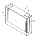
- FIG. 1 is a perspective view showing one embodiment of a nonaqueous electrolyte electricity storage element.
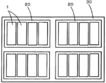
- FIG. 2 is a schematic diagram showing one embodiment of an electricity storage device formed by assembling a plurality of nonaqueous electrolyte electricity storage elements.
- a nonaqueous electrolyte storage element includes a positive electrode, a negative electrode, a separator, and a nonaqueous electrolyte, the nonaqueous electrolyte containing a nonaqueous solvent including a chain carboxylate ester and an additive that undergoes reductive decomposition on a surface of the negative electrode, and satisfies the following formula 1 when the volume of the nonaqueous electrolyte is Ve, the pore volume of the positive electrode is Vp, the pore volume of the negative electrode is Vn, and the pore volume of the separator is Vs: (Vp+Vn+Vs) ⁇ 1.1 ⁇ Ve...1
- the nonaqueous electrolyte storage element described in (1) above has a large initial input. The reason for this is unclear, but the following reason is presumed.
- the nonaqueous electrolyte storage element described in (1) above contains an additive that is reductively decomposed on the negative electrode surface. According to the knowledge of the inventors, in such a conventional nonaqueous electrolyte storage element, the additive is excessively reductively decomposed on the negative electrode surface during initial charging, and a thick coating may be formed on the negative electrode surface. Such a thick coating may be a factor in reducing the initial input of the nonaqueous electrolyte storage element.
- the additive may be at least one selected from the group consisting of unsaturated cyclic carbonates, fluorinated cyclic carbonates, oxalates containing phosphorus or boron, sulfonates containing fluorine, phosphates containing fluorine and oxygen, sulfates, and sulfonate esters.
- the nonaqueous electrolyte storage element described in (5) above has a high input power retention rate after charge-discharge cycles.
- the ratio (C/(A+B)) of the content C of the chain carboxylic acid ester to the total amount A of the unsaturated cyclic carbonate and the content B of the oxalate salt containing phosphorus or boron in the nonaqueous electrolyte may be 9.7 or more on a molar basis.
- the nonaqueous electrolyte storage element described in (6) above the unsaturated cyclic carbonate, the oxalate containing phosphorus or boron, and the chain carboxylate are reduced and decomposed in a balanced manner even during charge-discharge cycles, and the coating is maintained at an appropriate thickness on the negative electrode surface, so that an increase in resistance during charge-discharge cycles is suppressed. Therefore, the nonaqueous electrolyte storage element described in (5) above has a large input after charge-discharge cycles.
- additive refers to a compound, excluding chain carboxylate esters, whose content in the nonaqueous electrolyte before the initial charge/discharge is 10 mass% or less per compound.
- the volume of the nonaqueous electrolyte is calculated from the mass W 3 of the nonaqueous electrolyte and the density of the nonaqueous electrolyte.
- the density of the nonaqueous electrolyte is a value at 25 ° C., and is obtained by measuring the nonaqueous electrolyte taken out when the nonaqueous electrolyte storage element is dismantled using a liquid density meter.
- the "void volume" is measured by the following method.
- the nonaqueous electrolyte storage element is discharged at a constant current of 0.1 C to the discharge end voltage during normal use to be in a discharged state.
- normal use refers to the case where the nonaqueous electrolyte storage element is used under the charge and discharge conditions recommended or specified for the nonaqueous electrolyte storage element.
- the nonaqueous electrolyte storage element in this discharged state is disassembled, and the positive electrode, negative electrode, and separator to be measured are taken out and washed with dimethyl carbonate (DMC), and then dried under reduced pressure at room temperature for 24 hours.
- DMC dimethyl carbonate
- the apparent volume of the positive electrode active material layer can be calculated from the length, average thickness and width of the positive electrode active material layer.
- the average thickness is the average of the measured values at any five points (hereinafter, the same applies to the average thickness).
- the sum V 2 of the actual volumes of each material constituting the positive electrode active material layer can be calculated from the content of each material in the positive electrode active material layer and the true density of each material.
- the void volume of the negative electrode can be calculated as the difference between the apparent volume of the negative electrode and the sum of the actual volumes of the materials constituting the negative electrode. When the negative electrode is composed of a negative electrode base material having no voids and a negative electrode active material layer having voids, the void volume of the negative electrode is equal to the void volume of the negative electrode active material layer.
- the void volume of the negative electrode active material layer can be calculated in the same manner as the void volume of the positive electrode active material layer.
- the pore volume of the separator is calculated from the difference between the apparent volume and the actual volume of the separator.
- the apparent volume of the separator can be calculated from the length, average thickness and width of the separator.
- the actual volume of the separator can be calculated from the mass and true density of the separator.
- the pore volume of the separator can be calculated as the sum of the pore volumes of each member constituting the separator.
- the pore volume of the separator can be calculated as the sum of the pore volume of the substrate layer and the pore volume of the heat-resistant layer.
- the term "reduction potential” refers to the potential (vs. Li/Li + ) at the reduction peak (the reduction peak with the most noble potential observed in the first cycle) confirmed from the measurement results by cyclic voltammetry (CV).
- the CV method is carried out under the following measurement conditions. ⁇ Measurement condition ⁇
- Working electrode: graphite Reference electrode: metallic Li Solvent composition: EC:EMC 3:7 (volume ratio)
- the content A of the unsaturated cyclic carbonate, the content B of the oxalate containing phosphorus or boron, and the content C of the chain carboxylate in the nonaqueous electrolyte are the contents in the nonaqueous electrolyte taken out when the nonaqueous electrolyte storage element is disassembled.
- the content A of the unsaturated cyclic carbonate and the content C of the chain carboxylate in the nonaqueous electrolyte are determined by gas chromatography-mass spectrometry (GC-MS).
- the content B of oxalate containing phosphorus or boron is determined by ion chromatography (IC).
- nonaqueous electrolyte storage element a storage device, a method for manufacturing a nonaqueous electrolyte storage element according to one embodiment of the present invention, and other embodiments will be described in detail.
- the names of the components (elementary components) used in each embodiment may differ from the names of the components (elementary components) used in the background art.
- the nonaqueous electrolyte exists in a state that it is contained in the positive electrode, the negative electrode, and the separator.
- a nonaqueous electrolyte storage element a nonaqueous electrolyte secondary battery (hereinafter, also simply referred to as "secondary battery”) will be described.
- the positive electrode has a positive electrode substrate and a positive electrode active material layer disposed on the positive electrode substrate directly or via an intermediate layer.
- the positive electrode substrate has electrical conductivity. Whether or not the substrate has "electrical conductivity" is determined by using a volume resistivity of 10 -2 ⁇ cm measured in accordance with JIS-H-0505 (1975) as a threshold value.
- the material of the positive electrode substrate metals such as aluminum, titanium, tantalum, stainless steel, and alloys thereof are used. Among these, aluminum or aluminum alloys are preferred from the viewpoints of potential resistance, high electrical conductivity, and cost.
- foil, vapor deposition film, mesh, porous material, etc. are mentioned, and foil is preferred from the viewpoint of cost. Therefore, aluminum foil or aluminum alloy foil is preferred as the positive electrode substrate.
- As the aluminum or aluminum alloy A1085, A3003, A1N30, etc. specified in JIS-H-4000 (2014) or JIS-H-4160 (2006) can be exemplified.
- the average thickness of the positive electrode substrate is preferably 3 ⁇ m or more and 50 ⁇ m or less, more preferably 5 ⁇ m or more and 40 ⁇ m or less, even more preferably 8 ⁇ m or more and 30 ⁇ m or less, and particularly preferably 10 ⁇ m or more and 25 ⁇ m or less.
- the intermediate layer is a layer disposed between the positive electrode substrate and the positive electrode active material layer.
- the intermediate layer contains a conductive agent such as carbon particles to reduce the contact resistance between the positive electrode substrate and the positive electrode active material layer.
- the composition of the intermediate layer is not particularly limited, and may contain, for example, a binder and a conductive agent.
- the positive electrode active material layer contains a positive electrode active material.
- the positive electrode active material layer contains optional components such as a conductive agent, a binder, a thickener, and a filler, as necessary.
- the positive electrode active material can be appropriately selected from known positive electrode active materials.
- a material capable of absorbing and releasing lithium ions is usually used as the positive electrode active material for a lithium ion secondary battery.
- the positive electrode active material include lithium transition metal composite oxides having an ⁇ -NaFeO 2 type crystal structure, lithium transition metal composite oxides having a spinel type crystal structure, polyanion compounds, chalcogen compounds, sulfur, and the like.
- lithium transition metal composite oxides having an ⁇ -NaFeO2 type crystal structure examples include Li[Li x Ni (1-x) ]O 2 (0 ⁇ x ⁇ 0.5), Li[Li x Ni ⁇ Co (1-x- ⁇ ) ]O 2 (0 ⁇ x ⁇ 0.5, 0 ⁇ 1, 0 ⁇ 1-x- ⁇ ), Li[Li x Co (1-x) ]O 2 (0 ⁇ x ⁇ 0.5), Li[Li x Ni ⁇ Mn (1-x- ⁇ ) ]O 2 (0 ⁇ x ⁇ 0.5, 0 ⁇ 1, 0 ⁇ 1-x- ⁇ ), and Li[Li x Ni ⁇ Mn ⁇ Co (1-x- ⁇ - ⁇ ) ]O 2 (0 ⁇ x ⁇ 0.5, 0 ⁇ , 0 ⁇ , 0.5 ⁇ + ⁇ 1, 0 ⁇ 1-x- ⁇ - ⁇ ), Li[Li x Ni ⁇ Co ⁇ Al (1-x- ⁇ - ⁇ ) ]O 2 (0 ⁇ x ⁇ 0.5, 0 ⁇ , 0 ⁇ , 0.5 ⁇ + ⁇ 1, 0 ⁇ 1-x- ⁇
- lithium transition metal composite oxides having a spinel type crystal structure examples include Li x Mn 2 O 4 and Li x Ni ⁇ Mn (2- ⁇ ) O 4 .
- polyanion compounds examples include LiFePO4 , LiMnPO4 , LiNiPO4 , LiCoPO4, Li3V2 ( PO4 ) 3 , Li2MnSiO4 , and Li2CoPO4F .
- chalcogen compounds include titanium disulfide, molybdenum disulfide , and molybdenum dioxide. Atoms or polyanions in these materials may be partially substituted with atoms or anion species of other elements. The surfaces of these materials may be coated with other materials. In the positive electrode active material layer, one of these materials may be used alone, or two or more may be mixed and used.
- a lithium transition metal composite oxide is preferable, a lithium transition metal composite oxide containing at least one of nickel, cobalt and manganese is more preferable, a lithium transition metal composite oxide containing at least two of nickel, cobalt and manganese is even more preferable, and a lithium transition metal composite oxide containing nickel, cobalt and manganese is even more preferable.
- This lithium transition metal composite oxide preferably has an ⁇ -NaFeO 2 type crystal structure. By using such a lithium transition metal composite oxide, it is possible to increase the energy density, etc.
- the positive electrode active material is usually a particle (powder).
- the average particle size of the positive electrode active material is preferably, for example, 0.1 ⁇ m or more and 20 ⁇ m or less. By setting the average particle size of the positive electrode active material to the above lower limit or more, the positive electrode active material can be easily manufactured or handled. By setting the average particle size of the positive electrode active material to the above upper limit or less, the electronic conductivity of the positive electrode active material layer is improved. When a composite of the positive electrode active material and another material is used, the average particle size of the composite is taken as the average particle size of the positive electrode active material.
- a pulverizer or a classifier is used.
- pulverizing methods include those using a mortar, ball mill, sand mill, vibrating ball mill, planetary ball mill, jet mill, counter jet mill, swirling airflow type jet mill, or a sieve.
- Wet pulverization in the presence of water or an organic solvent such as hexane can also be used during pulverization.
- classification methods a sieve or an air classifier can be used as necessary for both dry and wet methods.
- the content of the positive electrode active material in the positive electrode active material layer is preferably 50% by mass or more and 99% by mass or less, more preferably 70% by mass or more and 98% by mass or less, and even more preferably 80% by mass or more and 95% by mass or less.
- the conductive agent is not particularly limited as long as it is a material having electrical conductivity.
- Examples of such conductive agents include carbonaceous materials, metals, conductive ceramics, etc.
- Examples of carbonaceous materials include graphite, non-graphitic carbon, graphene-based carbon, etc.
- Examples of non-graphitic carbon include carbon nanofibers, pitch-based carbon fibers, carbon black, etc.
- Examples of carbon black include furnace black, acetylene black, ketjen black, etc.
- Examples of graphene-based carbon include graphene, carbon nanotubes (CNT), fullerene, etc.
- Examples of the conductive agent include powder and fiber.
- the conductive agent one of these materials may be used alone, or two or more types may be mixed and used. These materials may also be used in combination.
- a material in which carbon black and CNT are combined may be used.
- carbon black is preferred from the viewpoints of electronic conductivity and coatability, and acetylene black is preferred among these.
- the filler is not particularly limited.
- the filler include polyolefins such as polypropylene and polyethylene, inorganic oxides such as silicon dioxide, alumina, titanium dioxide, calcium oxide, strontium oxide, barium oxide, magnesium oxide, and aluminosilicates, hydroxides such as magnesium hydroxide, calcium hydroxide, and aluminum hydroxide, carbonates such as calcium carbonate, poorly soluble ion crystals such as calcium fluoride, barium fluoride, and barium sulfate, nitrides such as aluminum nitride and silicon nitride, mineral resource-derived substances such as talc, montmorillonite, boehmite, zeolite, apatite, kaolin, mullite, spinel, olivine, sericite, bentonite, and mica, and artificial products thereof.
- polyolefins such as polypropylene and polyethylene
- inorganic oxides such as silicon dioxide, alumina, titanium dioxide,
- the negative electrode has a negative electrode substrate and a negative electrode active material layer disposed on the negative electrode substrate directly or via an intermediate layer.
- the configuration of the intermediate layer is not particularly limited and can be selected from the configurations exemplified for the positive electrode.
- the negative electrode substrate is conductive. Metals such as copper, nickel, stainless steel, nickel-plated steel, and aluminum, or alloys of these, carbonaceous materials, etc. are used as the material for the negative electrode substrate. Among these, copper or copper alloys are preferred. Examples of the negative electrode substrate include foil, vapor deposition film, mesh, and porous materials, with foil being preferred from the viewpoint of cost. Therefore, copper foil or copper alloy foil is preferred as the negative electrode substrate. Examples of copper foil include rolled copper foil and electrolytic copper foil.
- the average thickness of the negative electrode substrate is preferably 2 ⁇ m or more and 35 ⁇ m or less, more preferably 3 ⁇ m or more and 30 ⁇ m or less, even more preferably 4 ⁇ m or more and 25 ⁇ m or less, and particularly preferably 5 ⁇ m or more and 20 ⁇ m or less.
- the negative electrode active material layer contains a negative electrode active material.
- the negative electrode active material layer contains optional components such as a conductive agent, a binder, a thickener, and a filler as necessary.
- the optional components such as a conductive agent, a binder, a thickener, and a filler can be selected from the materials exemplified for the positive electrode above.
- the negative electrode active material layer may contain typical nonmetallic elements such as B, N, P, F, Cl, Br, and I, typical metallic elements such as Li, Na, Mg, Al, K, Ca, Zn, Ga, Ge, Sn, Sr, and Ba, and transition metallic elements such as Sc, Ti, V, Cr, Mn, Fe, Co, Ni, Cu, Mo, Zr, Ta, Hf, Nb, and W as components other than the negative electrode active material, conductive agent, binder, thickener, and filler.
- typical nonmetallic elements such as B, N, P, F, Cl, Br, and I
- typical metallic elements such as Li, Na, Mg, Al, K, Ca, Zn, Ga, Ge, Sn, Sr, and Ba
- transition metallic elements such as Sc, Ti, V, Cr, Mn, Fe, Co, Ni, Cu, Mo, Zr, Ta, Hf, Nb, and W as components other than the negative electrode active material, conductive agent, binder, thickener, and filler.
- the negative electrode active material can be appropriately selected from known negative electrode active materials.
- the negative electrode active material for lithium ion secondary batteries a material capable of absorbing and releasing lithium ions is usually used.
- the negative electrode active material include metal Li; metals or semimetals such as Si and Sn; metal oxides or semimetal oxides such as Si oxide, Ti oxide, and Sn oxide; titanium-containing oxides such as Li 4 Ti 5 O 12 , LiTiO 2, and TiNb 2 O 7 ; polyphosphate compounds; silicon carbide; carbon materials such as graphite and non-graphitic carbon (easily graphitized carbon or non-graphitizable carbon). Among these materials, graphite and non-graphitic carbon are preferred. In the negative electrode active material layer, one of these materials may be used alone, or two or more may be mixed and used.
- Graphite refers to a carbon material having an average lattice spacing (d 002 ) of the (002) plane determined by X-ray diffraction before charging and discharging or in a discharged state of 0.33 nm or more and less than 0.34 nm.
- Examples of graphite include natural graphite and artificial graphite. Artificial graphite is preferred from the viewpoint of obtaining a material with stable physical properties.
- Non-graphitic carbon refers to a carbon material having an average lattice spacing (d002) of 0.34 nm or more and 0.42 nm or less of ( 002 ) plane determined by X-ray diffraction before charging and discharging or in a discharged state.
- Examples of non-graphitic carbon include non-graphitizable carbon and graphitizable carbon.
- Examples of non-graphitic carbon include resin-derived materials, petroleum pitch or petroleum pitch-derived materials, petroleum coke or petroleum coke-derived materials, plant-derived materials, and alcohol-derived materials.
- the discharged state of the carbon material refers to a state in which the carbon material, which is the negative electrode active material, is discharged so that lithium ions that can be absorbed and released during charging and discharging are sufficiently released.
- the carbon material which is the negative electrode active material
- metallic Li as the counter electrode
- non-graphitizable carbon refers to a carbon material having the above d002 of 0.36 nm or more and 0.42 nm or less.
- graphitizable carbon refers to a carbon material having the above d002 of 0.34 nm or more and less than 0.36 nm.
- the negative electrode active material is usually a particle (powder).
- the average particle size of the negative electrode active material can be, for example, 1 nm or more and 100 ⁇ m or less.
- the negative electrode active material is a carbon material, a titanium-containing oxide, or a polyphosphate compound
- the average particle size may be 1 ⁇ m or more and 100 ⁇ m or less.
- the negative electrode active material is Si, Sn, Si oxide, Sn oxide, or the like
- the average particle size may be 1 nm or more and 1 ⁇ m or less.
- the electronic conductivity of the negative electrode active material layer is improved.
- a pulverizer, a classifier, or the like is used.
- the pulverizing method and the classifying method can be selected from, for example, the methods exemplified for the positive electrode above.
- the negative electrode active material is a metal such as metallic Li
- the negative electrode active material layer may be in the form of a foil.
- the content of the negative electrode active material in the negative electrode active material layer is preferably 60% by mass or more and 99% by mass or less, and more preferably 90% by mass or more and 98% by mass or less. By setting the content of the negative electrode active material in the above range, it is possible to achieve both high energy density and manufacturability of the negative electrode active material layer.
- the content of the negative electrode active material in the negative electrode active material layer may be 99% by mass or more, or may be 100% by mass.
- the chain carboxylate contained in the non-aqueous solvent may be a compound represented by the chemical formula [R 1 (COO)R 2 ].
- R 1 and R 2 are saturated or unsaturated hydrocarbon groups having 1 to 5 carbon atoms (preferably 1 to 3, more preferably 1 or 2).
- R 1 may be the same as or different from R 2.
- R 1 and R 2 may be linear or branched.
- the hydrogen atoms in R 1 and R 2 may be partially substituted with halogens (e.g., fluorine (F) atoms, chlorine (Cl) atoms, bromine (Br) atoms), etc.
- chain carboxylate esters examples include methyl propionate, ethyl propionate, propyl propionate, methyl acetate, ethyl acetate, propyl acetate, methyl butyrate, ethyl butyrate, propyl butyrate, methyl acrylate, and methyl methacrylate.
- propionate esters which are easily reductively decomposed on the negative electrode surface, are preferred, and methyl propionate is more preferred.
- Chain carboxylate esters may be used alone or in combination of two or more types.
- non-aqueous solvents other than the chain carboxylate esters can be appropriately selected from known non-aqueous solvents.
- examples of the other non-aqueous solvents include cyclic carbonates, chain carbonates, cyclic carboxylate esters, phosphate esters, ethers, amides, and nitriles.
- Non-aqueous solvents in which some of the hydrogen atoms contained in these compounds have been replaced with halogens may also be used.
- chain carbonates examples include diethyl carbonate (DEC), dimethyl carbonate (DMC), ethyl methyl carbonate (EMC), diphenyl carbonate, trifluoroethyl methyl carbonate, bis(trifluoroethyl) carbonate, etc. Among these, EMC and DMC are preferred.
- the content of the electrolyte salt in the nonaqueous electrolyte solution is preferably 0.1 mol/dm 3 or more and 2.5 mol/dm 3 or less, more preferably 0.3 mol/dm 3 or more and 2.0 mol/dm 3 or less, even more preferably 0.5 mol/dm 3 or more and 1.7 mol/dm 3 or less, and particularly preferably 0.7 mol/dm 3 or more and 1.5 mol/dm 3 or less, at 25° C. and 1 atmospheric pressure.
- Additives that undergo reductive decomposition on the negative electrode surface can exhibit the above-mentioned reduction potential and can easily form a good coating on the negative electrode surface, and therefore include unsaturated cyclic carbonates, fluorinated cyclic carbonates, oxalates containing phosphorus or boron, sulfonates containing fluorine, phosphates containing fluorine and oxygen, sulfates, and sulfonate esters. These may be used alone or in combination of two or more.
- the upper limit of the ratio (C/A) may be even more preferably 27.0.
- the ratio (C/A) after the initial charge and discharge may be equal to or greater than any of the lower limits and equal to or less than any of the upper limits. If the ratio (C/A) in the nonaqueous electrolyte after the initial charge/discharge is within the above range, the input after the charge/discharge cycle can be made larger.
- the lower limit of the content (residual amount) of the phosphate containing fluorine and oxygen elements in the non-aqueous electrolyte after the initial charge and discharge is preferably 0.05 mol / dm 3 , more preferably 0.1 mol / dm 3 , even more preferably 0.5 mol / dm 3 , and even more preferably 0.7 mol / dm 3.
- the content of the sulfates before the initial charge/discharge may be equal to or greater than any of the lower limits and equal to or less than any of the upper limits. When the content of sulfates is within the above range, the above-mentioned effects can be better exhibited.
- the content of the sulfates after the initial charge and discharge may be equal to or greater than any of the lower limits and equal to or less than any of the upper limits. If the content of the phosphate containing the sulfates after the initial charge and discharge is within the above range, the input after the charge and discharge cycle can be increased.
- the lower limit of the content of the sulfonate esters in the non-aqueous electrolyte before the initial charge/discharge is preferably 0.1 mass%, more preferably 0.2 mass%, even more preferably 0.3 mass%, and even more preferably 0.4 mass%, relative to the total mass of the non-aqueous electrolyte.
- the upper limit of the content of the sulfonate esters is preferably 5.0 mass%, more preferably 3.0 mass%, even more preferably 2.0 mass%, and even more preferably 1.0 mass%.
- the upper limit of the molar ratio may be 10.0 or 9.0.
- the molar ratio may be 3.0 or more and 20.0 or less, 6.4 or more and 14.4 or less, 6.4 or more and 10.0 or less, or 6.4 or more and 8.0 or less.
- the molar ratio may be 7.0 or more and 25.0 or less, 8.5 or more and 20.0 or less, or 9.7 or more and 14.4 or less.
- the molar ratio may be any lower limit or more and any upper limit or less (however, the lower limit is a value smaller than the upper limit).
- the non-aqueous electrolyte may contain additives other than the additives mentioned above.
- the other additives may be additives that undergo reductive decomposition at the negative electrode, or may not undergo reductive decomposition at the negative electrode.
- the other additives include aromatic compounds such as biphenyl, alkylbiphenyl, terphenyl, partially hydrogenated terphenyl, cyclohexylbenzene, t-butylbenzene, t-amylbenzene, diphenyl ether, and dibenzofuran; partial halides of the aromatic compounds such as 2-fluorobiphenyl, o-cyclohexylfluorobenzene, and p-cyclohexylfluorobenzene; halogenated aryl compounds such as 2,4-difluoroanisole, 2,5-difluoroanisole, 2,6-difluoroanisole, and 3,5-difluoroanisole.
- the lower limit of the volume Ve of the non-aqueous electrolyte is preferably 25.6 cm 3 , more preferably 30.2 cm 3 , and even more preferably 34.9 cm 3 .
- the upper limit of the volume Ve of the non-aqueous electrolyte is preferably 44.2 cm 3 , and more preferably 39.5 cm 3 .
- the lower limit of the void volume Vn of the negative electrode is preferably 7.7 cm 3 , more preferably 8.8 cm 3 , and even more preferably 10.0 cm 3 .
- the upper limit of the volume Vn of the negative electrode is preferably 12.2 cm 3 , and more preferably 11.1 cm 3 . When the volume Vn of the negative electrode is within the above range, the above-mentioned effects can be better exhibited.
- the lower limit of the separator void volume Vs is preferably 6.7 cm 3 , more preferably 6.9 cm 3 , and even more preferably 7.0 cm 3 .
- the upper limit of the separator volume Vs is preferably 7.6 cm 3 , and more preferably 7.4 cm 3 .
- the shape of the nonaqueous electrolyte storage element of this embodiment is not particularly limited, and examples thereof include a cylindrical battery, a prismatic battery, a flat battery, a coin battery, and a button battery.
- Fig. 1 shows a nonaqueous electrolyte storage element 1 as an example of a prismatic battery. The figure is a see-through view of the inside of the container.
- An electrode body 2 having a positive electrode and a negative electrode wound with a separator sandwiched therebetween is housed in a prismatic container 3.
- the positive electrode is electrically connected to a positive electrode terminal 4 via a positive electrode lead 41.
- the negative electrode is electrically connected to a negative electrode terminal 5 via a negative electrode lead 51.
- the electricity storage device 30 may include a bus bar (not shown) that electrically connects two or more nonaqueous electrolyte electricity storage elements 1, a bus bar (not shown) that electrically connects two or more electricity storage units 20, and the like.
- the electricity storage unit 20 or the electricity storage device 30 may include a status monitoring device (not shown) that monitors the status of one or more nonaqueous electrolyte electricity storage elements.
- the method for producing the nonaqueous electrolyte storage element of the present embodiment can be appropriately selected from known methods.
- the method for producing the nonaqueous electrolyte storage element of the present embodiment includes, for example, preparing an electrode body, preparing a nonaqueous electrolyte, and housing the electrode body and the nonaqueous electrolyte in a container.
- the preparation of the electrode body includes preparing a positive electrode and a negative electrode, and forming the electrode body by stacking or rolling the positive electrode and the negative electrode with a separator interposed therebetween.
- the method of storing the non-aqueous electrolyte in the container can be appropriately selected from among known methods. For example, when a non-aqueous electrolyte solution is used as the non-aqueous electrolyte, the non-aqueous electrolyte solution can be injected through an injection port formed in the container, and then the injection port can be sealed.
- the nonaqueous electrolyte storage element of the present invention is not limited to the above-described embodiment, and various modifications may be made without departing from the scope of the present invention.
- the configuration of one embodiment may be added to the configuration of another embodiment, and part of the configuration of one embodiment may be replaced with the configuration of another embodiment or a well-known technique.
- part of the configuration of one embodiment may be deleted.
- a well-known technique may be added to the configuration of one embodiment.
- the nonaqueous electrolyte storage element is used as a chargeable and dischargeable nonaqueous electrolyte secondary battery (e.g., a lithium ion secondary battery), but the type, shape, size, capacity, etc. of the nonaqueous electrolyte storage element are arbitrary.
- the present invention can also be applied to various secondary batteries, electric double layer capacitors, lithium ion capacitors, and other capacitors.
- LiNi 1/3 Mn 1/3 Co 1/3 O 2 was prepared as the positive electrode active material.
- a positive electrode mixture paste was prepared containing the positive electrode active material, acetylene black (AB) as a conductive agent, and polyvinylidene fluoride (PVDF) as a binder in a mass ratio of 90:5:5 in terms of solid content, using N-methylpyrrolidone (NMP) as a dispersion medium.
- NMP N-methylpyrrolidone
- LiPF6 was dissolved as an electrolyte salt at a content of 1.2 mol/dm3 in a non-aqueous solvent in which EC, DMC, EMC and MP were mixed in a volume ratio (volume%) of 30:35:32: 3 .
- vinylene carbonate (VC) was dissolved as an additive at a content of 0.2 mass% and lithium bis(oxalate)borate (LiBOB) was dissolved at a content of 0.5 mass% in this solution.
- the reduction potential of VC was 0.6 V vs. Li/Li +
- the reduction potential of LiBOB was 1.6 V vs.
- LiPF6 LiPF6 was dissolved as an electrolyte salt at a content of 1.2 mol/ dm3 in a non-aqueous solvent in which EC, DMC and EMC were mixed at a volume ratio (volume %) of 30:35:35.
- additives were dissolved in this solution in the same manner as in the "electricity storage element with MP".
- the positive electrode and the negative electrode were laminated with a polyolefin microporous membrane separator interposed therebetween to produce an electrode assembly.
- This electrode assembly was placed in a container made of a metal resin composite film, and the nonaqueous electrolyte was poured into the container so that the coefficient ⁇ calculated by the above-mentioned formula 2 was a target value.
- the container was then sealed by heat welding to obtain a "power storage element with MP" and a "power storage element without MP", respectively.
- the rated capacity was the initial discharge capacity. After each discharge was completed, constant current discharge was performed at a current of 0.2C to set the SOC to 50%. The resistance value was calculated from the slope of the voltage in each charge and the current 1 second after the start of charging, and " ⁇ difference between the voltage before charging and the upper limit voltage (4.3V) ⁇ /resistance value x upper limit voltage (4.3V)" was calculated and used as the "initial input”.
- the ratio of each initial input to the initial input when the coefficient ⁇ was 1.55 was calculated and defined as the “initial input ratio.”
- the relationship between the coefficient ⁇ and the initial input ratio as the relationship between the amount of nonaqueous electrolyte and the initial input of the nonaqueous electrolyte storage element is shown in Table 1.
- the "energy storage element without MP” maintains an initial input ratio of approximately 1.00 even when the value of the coefficient ⁇ changes.
- the "energy storage element with MP” maintains an initial input ratio of approximately 1.00 when the coefficient ⁇ is 1.1 or more, but the initial input ratio decreases when the coefficient ⁇ is smaller than 1.1. From this, it is presumed that when the amount of non-aqueous electrolyte is small, the effect of methyl propionate (MP) in suppressing the reductive decomposition of the additive is excessively exerted, resulting in an increase in the resistance of the coating on the negative electrode surface.
- MP methyl propionate
- ⁇ Test Example 2 Relationship between MP content and input>
- a nonaqueous electrolyte storage element was first produced by the following procedure. Then, the input power was evaluated for nonaqueous electrolyte storage elements with different MP contents.
- the nonaqueous electrolyte storage elements having an MP content of 3 volume % (Example 2), 5 volume % (Example 3), and 7 volume % (Example 4) in the nonaqueous solvent before the initial charge and discharge all have a larger initial input power than the nonaqueous electrolyte storage element having an MP content of 0 volume % (Example 1).
- the nonaqueous electrolyte storage element of Example 3 has an MP content of 5 volume % in the nonaqueous solvent before the initial charge and discharge, and a molar ratio (C/(A+B)) of 9.7.
- the nonaqueous electrolyte storage element of Example 3 had the largest input power after the charge and discharge cycle.
Landscapes
- Engineering & Computer Science (AREA)
- Chemical & Material Sciences (AREA)
- Power Engineering (AREA)
- Chemical Kinetics & Catalysis (AREA)
- Electrochemistry (AREA)
- Microelectronics & Electronic Packaging (AREA)
- General Chemical & Material Sciences (AREA)
- Manufacturing & Machinery (AREA)
- Materials Engineering (AREA)
- Physics & Mathematics (AREA)
- Condensed Matter Physics & Semiconductors (AREA)
- General Physics & Mathematics (AREA)
- Inorganic Chemistry (AREA)
- Secondary Cells (AREA)
Priority Applications (3)
| Application Number | Priority Date | Filing Date | Title |
|---|---|---|---|
| JP2024568897A JPWO2024147290A1 (https=) | 2023-01-05 | 2023-12-21 | |
| EP23914776.2A EP4632864A4 (en) | 2023-01-05 | 2023-12-21 | NON-AQUEOUS ELECTROLYTE ELECTRICAL STORAGE ELEMENT |
| CN202380090485.5A CN120457576A (zh) | 2023-01-05 | 2023-12-21 | 非水电解质蓄电元件 |
Applications Claiming Priority (2)
| Application Number | Priority Date | Filing Date | Title |
|---|---|---|---|
| JP2023000733 | 2023-01-05 | ||
| JP2023-000733 | 2023-01-05 |
Publications (1)
| Publication Number | Publication Date |
|---|---|
| WO2024147290A1 true WO2024147290A1 (ja) | 2024-07-11 |
Family
ID=91803817
Family Applications (1)
| Application Number | Title | Priority Date | Filing Date |
|---|---|---|---|
| PCT/JP2023/045854 Ceased WO2024147290A1 (ja) | 2023-01-05 | 2023-12-21 | 非水電解質蓄電素子 |
Country Status (4)
| Country | Link |
|---|---|
| EP (1) | EP4632864A4 (https=) |
| JP (1) | JPWO2024147290A1 (https=) |
| CN (1) | CN120457576A (https=) |
| WO (1) | WO2024147290A1 (https=) |
Citations (7)
| Publication number | Priority date | Publication date | Assignee | Title |
|---|---|---|---|---|
| JP2004319212A (ja) | 2003-04-15 | 2004-11-11 | Sony Corp | 電解液およびそれを用いた電池 |
| JP2008135273A (ja) * | 2006-11-28 | 2008-06-12 | Sony Corp | 電解液および電池 |
| JP2014199775A (ja) * | 2013-03-29 | 2014-10-23 | 株式会社Gsユアサ | 蓄電素子及び車載用蓄電池システム |
| JP2015069810A (ja) * | 2013-09-27 | 2015-04-13 | オートモーティブエナジーサプライ株式会社 | 非水電解質二次電池およびその製造方法 |
| WO2021060414A1 (ja) * | 2019-09-25 | 2021-04-01 | 積水化学工業株式会社 | 蓄電素子及び蓄電素子の製造方法 |
| WO2021166663A1 (ja) * | 2020-02-20 | 2021-08-26 | 株式会社豊田自動織機 | リチウムイオン二次電池 |
| US20220252498A1 (en) * | 2021-02-05 | 2022-08-11 | Ningde Amperex Technology Limited | Method for determining injection mass of electrolyte for battery |
Family Cites Families (2)
| Publication number | Priority date | Publication date | Assignee | Title |
|---|---|---|---|---|
| JP2017191744A (ja) * | 2016-04-15 | 2017-10-19 | 国立大学法人 東京大学 | リチウムイオン二次電池 |
| US20230006255A1 (en) * | 2019-12-03 | 2023-01-05 | Solvay Sa | Electrolyte composition with fluorinated acyclic ester and fluorinated cyclic carbonate |
-
2023
- 2023-12-21 JP JP2024568897A patent/JPWO2024147290A1/ja active Pending
- 2023-12-21 EP EP23914776.2A patent/EP4632864A4/en active Pending
- 2023-12-21 WO PCT/JP2023/045854 patent/WO2024147290A1/ja not_active Ceased
- 2023-12-21 CN CN202380090485.5A patent/CN120457576A/zh active Pending
Patent Citations (7)
| Publication number | Priority date | Publication date | Assignee | Title |
|---|---|---|---|---|
| JP2004319212A (ja) | 2003-04-15 | 2004-11-11 | Sony Corp | 電解液およびそれを用いた電池 |
| JP2008135273A (ja) * | 2006-11-28 | 2008-06-12 | Sony Corp | 電解液および電池 |
| JP2014199775A (ja) * | 2013-03-29 | 2014-10-23 | 株式会社Gsユアサ | 蓄電素子及び車載用蓄電池システム |
| JP2015069810A (ja) * | 2013-09-27 | 2015-04-13 | オートモーティブエナジーサプライ株式会社 | 非水電解質二次電池およびその製造方法 |
| WO2021060414A1 (ja) * | 2019-09-25 | 2021-04-01 | 積水化学工業株式会社 | 蓄電素子及び蓄電素子の製造方法 |
| WO2021166663A1 (ja) * | 2020-02-20 | 2021-08-26 | 株式会社豊田自動織機 | リチウムイオン二次電池 |
| US20220252498A1 (en) * | 2021-02-05 | 2022-08-11 | Ningde Amperex Technology Limited | Method for determining injection mass of electrolyte for battery |
Non-Patent Citations (1)
| Title |
|---|
| See also references of EP4632864A1 |
Also Published As
| Publication number | Publication date |
|---|---|
| CN120457576A (zh) | 2025-08-08 |
| EP4632864A4 (en) | 2026-03-18 |
| EP4632864A1 (en) | 2025-10-15 |
| JPWO2024147290A1 (https=) | 2024-07-11 |
Similar Documents
| Publication | Publication Date | Title |
|---|---|---|
| JP7816145B2 (ja) | 正極及び蓄電素子 | |
| JP7803334B2 (ja) | 非水電解質蓄電素子 | |
| JP7676834B2 (ja) | 非水電解質蓄電素子 | |
| JP7552227B2 (ja) | 蓄電素子 | |
| JP7700783B2 (ja) | 蓄電素子、その製造方法及び蓄電装置 | |
| JP7581762B2 (ja) | 蓄電素子用正極及び蓄電素子 | |
| JP7709111B2 (ja) | 非水電解質蓄電素子用正極合剤、非水電解質蓄電素子用正極及び非水電解質蓄電素子 | |
| JP7683485B2 (ja) | 蓄電素子及び蓄電装置 | |
| JP7604838B2 (ja) | 蓄電素子 | |
| JP2024001780A (ja) | 正極及び非水電解質蓄電素子 | |
| JP7532898B2 (ja) | 正極及び蓄電素子 | |
| WO2023281960A1 (ja) | 正極、蓄電素子及び蓄電装置 | |
| JP7725830B2 (ja) | 非水電解質蓄電素子及び非水電解質蓄電素子の製造方法 | |
| WO2024147290A1 (ja) | 非水電解質蓄電素子 | |
| JP7816348B2 (ja) | 非水電解質蓄電素子及び蓄電装置 | |
| JP7665932B2 (ja) | 非水電解質蓄電素子及び非水電解質蓄電素子の製造方法 | |
| JP2026028507A (ja) | 非水電解質及び非水電解質蓄電素子 | |
| WO2024075531A1 (ja) | 非水電解質蓄電素子 | |
| JP2024057590A (ja) | 非水電解質蓄電素子の製造方法及び非水電解質蓄電素子 | |
| JP2024047350A (ja) | 非水電解質、非水電解質蓄電素子及び非水電解質蓄電素子の製造方法 | |
| JP2023117881A (ja) | 非水電解液蓄電素子 | |
| WO2024236911A1 (ja) | 蓄電素子及び蓄電装置 | |
| WO2024176607A1 (ja) | 蓄電素子用正極、蓄電素子及び蓄電装置 | |
| JP2025086266A (ja) | 非水電解質蓄電素子の使用方法及び機器 | |
| JP2025110309A (ja) | 非水電解液蓄電素子及びその製造方法 |
Legal Events
| Date | Code | Title | Description |
|---|---|---|---|
| 121 | Ep: the epo has been informed by wipo that ep was designated in this application |
Ref document number: 23914776 Country of ref document: EP Kind code of ref document: A1 |
|
| WWE | Wipo information: entry into national phase |
Ref document number: 2024568897 Country of ref document: JP |
|
| WWE | Wipo information: entry into national phase |
Ref document number: 202380090485.5 Country of ref document: CN |
|
| WWE | Wipo information: entry into national phase |
Ref document number: 2023914776 Country of ref document: EP |
|
| ENP | Entry into the national phase |
Ref document number: 2023914776 Country of ref document: EP Effective date: 20250707 |
|
| NENP | Non-entry into the national phase |
Ref country code: DE |
|
| WWP | Wipo information: published in national office |
Ref document number: 202380090485.5 Country of ref document: CN |
|
| WWP | Wipo information: published in national office |
Ref document number: 2023914776 Country of ref document: EP |