WO2024142174A1 - 磁性成形体の製造方法、及び異方性ボンド磁石の製造方法 - Google Patents
磁性成形体の製造方法、及び異方性ボンド磁石の製造方法 Download PDFInfo
- Publication number
- WO2024142174A1 WO2024142174A1 PCT/JP2022/048013 JP2022048013W WO2024142174A1 WO 2024142174 A1 WO2024142174 A1 WO 2024142174A1 JP 2022048013 W JP2022048013 W JP 2022048013W WO 2024142174 A1 WO2024142174 A1 WO 2024142174A1
- Authority
- WO
- WIPO (PCT)
- Prior art keywords
- compound
- magnetic
- wax
- magnet
- molding
- Prior art date
- Legal status (The legal status is an assumption and is not a legal conclusion. Google has not performed a legal analysis and makes no representation as to the accuracy of the status listed.)
- Ceased
Links
Images


Classifications
-
- B—PERFORMING OPERATIONS; TRANSPORTING
- B22—CASTING; POWDER METALLURGY
- B22F—WORKING METALLIC POWDER; MANUFACTURE OF ARTICLES FROM METALLIC POWDER; MAKING METALLIC POWDER; APPARATUS OR DEVICES SPECIALLY ADAPTED FOR METALLIC POWDER
- B22F1/00—Metallic powder; Treatment of metallic powder, e.g. to facilitate working or to improve properties
-
- B—PERFORMING OPERATIONS; TRANSPORTING
- B22—CASTING; POWDER METALLURGY
- B22F—WORKING METALLIC POWDER; MANUFACTURE OF ARTICLES FROM METALLIC POWDER; MAKING METALLIC POWDER; APPARATUS OR DEVICES SPECIALLY ADAPTED FOR METALLIC POWDER
- B22F3/00—Manufacture of workpieces or articles from metallic powder characterised by the manner of compacting or sintering; Apparatus specially adapted therefor ; Presses and furnaces
-
- B—PERFORMING OPERATIONS; TRANSPORTING
- B22—CASTING; POWDER METALLURGY
- B22F—WORKING METALLIC POWDER; MANUFACTURE OF ARTICLES FROM METALLIC POWDER; MAKING METALLIC POWDER; APPARATUS OR DEVICES SPECIALLY ADAPTED FOR METALLIC POWDER
- B22F3/00—Manufacture of workpieces or articles from metallic powder characterised by the manner of compacting or sintering; Apparatus specially adapted therefor ; Presses and furnaces
- B22F3/02—Compacting only
-
- B—PERFORMING OPERATIONS; TRANSPORTING
- B22—CASTING; POWDER METALLURGY
- B22F—WORKING METALLIC POWDER; MANUFACTURE OF ARTICLES FROM METALLIC POWDER; MAKING METALLIC POWDER; APPARATUS OR DEVICES SPECIALLY ADAPTED FOR METALLIC POWDER
- B22F3/00—Manufacture of workpieces or articles from metallic powder characterised by the manner of compacting or sintering; Apparatus specially adapted therefor ; Presses and furnaces
- B22F3/10—Sintering only
-
- B—PERFORMING OPERATIONS; TRANSPORTING
- B22—CASTING; POWDER METALLURGY
- B22F—WORKING METALLIC POWDER; MANUFACTURE OF ARTICLES FROM METALLIC POWDER; MAKING METALLIC POWDER; APPARATUS OR DEVICES SPECIALLY ADAPTED FOR METALLIC POWDER
- B22F3/00—Manufacture of workpieces or articles from metallic powder characterised by the manner of compacting or sintering; Apparatus specially adapted therefor ; Presses and furnaces
- B22F3/24—After-treatment of workpieces or articles
-
- H—ELECTRICITY
- H01—ELECTRIC ELEMENTS
- H01F—MAGNETS; INDUCTANCES; TRANSFORMERS; SELECTION OF MATERIALS FOR THEIR MAGNETIC PROPERTIES
- H01F1/00—Magnets or magnetic bodies characterised by the magnetic materials therefor; Selection of materials for their magnetic properties
- H01F1/01—Magnets or magnetic bodies characterised by the magnetic materials therefor; Selection of materials for their magnetic properties of inorganic materials
- H01F1/03—Magnets or magnetic bodies characterised by the magnetic materials therefor; Selection of materials for their magnetic properties of inorganic materials characterised by their coercivity
- H01F1/032—Magnets or magnetic bodies characterised by the magnetic materials therefor; Selection of materials for their magnetic properties of inorganic materials characterised by their coercivity of hard-magnetic materials
- H01F1/04—Magnets or magnetic bodies characterised by the magnetic materials therefor; Selection of materials for their magnetic properties of inorganic materials characterised by their coercivity of hard-magnetic materials metals or alloys
- H01F1/047—Alloys characterised by their composition
- H01F1/053—Alloys characterised by their composition containing rare earth metals
- H01F1/055—Alloys characterised by their composition containing rare earth metals and magnetic transition metals, e.g. SmCo5
-
- H—ELECTRICITY
- H01—ELECTRIC ELEMENTS
- H01F—MAGNETS; INDUCTANCES; TRANSFORMERS; SELECTION OF MATERIALS FOR THEIR MAGNETIC PROPERTIES
- H01F1/00—Magnets or magnetic bodies characterised by the magnetic materials therefor; Selection of materials for their magnetic properties
- H01F1/01—Magnets or magnetic bodies characterised by the magnetic materials therefor; Selection of materials for their magnetic properties of inorganic materials
- H01F1/03—Magnets or magnetic bodies characterised by the magnetic materials therefor; Selection of materials for their magnetic properties of inorganic materials characterised by their coercivity
- H01F1/032—Magnets or magnetic bodies characterised by the magnetic materials therefor; Selection of materials for their magnetic properties of inorganic materials characterised by their coercivity of hard-magnetic materials
- H01F1/04—Magnets or magnetic bodies characterised by the magnetic materials therefor; Selection of materials for their magnetic properties of inorganic materials characterised by their coercivity of hard-magnetic materials metals or alloys
- H01F1/047—Alloys characterised by their composition
- H01F1/053—Alloys characterised by their composition containing rare earth metals
- H01F1/055—Alloys characterised by their composition containing rare earth metals and magnetic transition metals, e.g. SmCo5
- H01F1/059—Alloys characterised by their composition containing rare earth metals and magnetic transition metals, e.g. SmCo5 and Va elements, e.g. Sm2Fe17N2
-
- H—ELECTRICITY
- H01—ELECTRIC ELEMENTS
- H01F—MAGNETS; INDUCTANCES; TRANSFORMERS; SELECTION OF MATERIALS FOR THEIR MAGNETIC PROPERTIES
- H01F1/00—Magnets or magnetic bodies characterised by the magnetic materials therefor; Selection of materials for their magnetic properties
- H01F1/01—Magnets or magnetic bodies characterised by the magnetic materials therefor; Selection of materials for their magnetic properties of inorganic materials
- H01F1/03—Magnets or magnetic bodies characterised by the magnetic materials therefor; Selection of materials for their magnetic properties of inorganic materials characterised by their coercivity
- H01F1/032—Magnets or magnetic bodies characterised by the magnetic materials therefor; Selection of materials for their magnetic properties of inorganic materials characterised by their coercivity of hard-magnetic materials
- H01F1/04—Magnets or magnetic bodies characterised by the magnetic materials therefor; Selection of materials for their magnetic properties of inorganic materials characterised by their coercivity of hard-magnetic materials metals or alloys
- H01F1/06—Magnets or magnetic bodies characterised by the magnetic materials therefor; Selection of materials for their magnetic properties of inorganic materials characterised by their coercivity of hard-magnetic materials metals or alloys in the form of particles, e.g. powder
- H01F1/08—Magnets or magnetic bodies characterised by the magnetic materials therefor; Selection of materials for their magnetic properties of inorganic materials characterised by their coercivity of hard-magnetic materials metals or alloys in the form of particles, e.g. powder pressed, sintered, or bound together
-
- H—ELECTRICITY
- H01—ELECTRIC ELEMENTS
- H01F—MAGNETS; INDUCTANCES; TRANSFORMERS; SELECTION OF MATERIALS FOR THEIR MAGNETIC PROPERTIES
- H01F41/00—Apparatus or processes specially adapted for manufacturing or assembling magnets, inductances or transformers; Apparatus or processes specially adapted for manufacturing materials characterised by their magnetic properties
- H01F41/02—Apparatus or processes specially adapted for manufacturing or assembling magnets, inductances or transformers; Apparatus or processes specially adapted for manufacturing materials characterised by their magnetic properties for manufacturing cores, coils, or magnets
Definitions
- a method for manufacturing a magnetic compact for use in producing an anisotropic bonded magnet with excellent residual magnetic flux density and mechanical strength and a method for producing an anisotropic bonded magnet with excellent residual magnetic flux density and mechanical strength.
- the manufacturing apparatus 10 further includes a power supply mechanism.
- the power supply mechanism is electrically connected to each of the first coil c1 and the second coil c2.
- the power supply mechanism freely controls the direction and absolute value of the first current generated in the first coil c1 and the direction and absolute value of the second current generated in the second coil c2.
- the power supply mechanism is omitted in each figure.
- the dropping point of the wax is a value that depends on the composition of the wax and is not limited.
- the heat curing temperature of the thermosetting resin is a value that depends on the composition of the thermosetting resin and is not limited.
- the molding temperature Tm is a value that depends on the combination of the wax and the thermosetting resin and is not limited.
- the molding temperature Tm may be 60°C or higher and 150°C or lower, preferably 70°C or higher and 110°C or lower, and more preferably 80°C or higher and 100°C or lower.
- the sum of the mass of the magnet powder and the mass of the thermosetting resin is represented as M1 (unit: g).
- the mass of the wax in the compound is represented as M2 (unit: g).
- (M2/M1) x 100 may be 2 to 10, 2.5 to 8, 2 to 5, or 2.0 to 4.0.
- (M2/M1) x 100 is 2 or more, due to the lubricity of the wax 4, each magnet particle 3 is likely to rotate and each magnet particle 3 is likely to be oriented along the magnetic field H.
- (M2/M1) x 100 is 10 or less, most of the wax is likely to be removed from the molded body during the molding process, and the wax is unlikely to remain in the anisotropic bonded magnet, and the anisotropic bonded magnet is likely to have high mechanical strength.
- the application of a magnetic field to the compound in the mold may be started simultaneously with the compression of the compound in the mold.
- the application of a magnetic field to the compound in the mold may be started earlier than the compression of the compound in the mold. If the application of a magnetic field to the compound in the mold is started earlier than the compression of the compound in the mold, each magnetic particle in the compound is likely to rotate in a state in which the compression of the compound is suppressed. As a result, each magnetic particle is likely to be oriented along the magnetic field.
- the application of a magnetic field to the compound in the mold may be stopped at the point when the molding pressure P starts to decrease.
- the magnetic field H may be a static magnetic field (a continuous constant magnetic field).
- the magnetic field H may be a pulsed magnetic field (a pulsed magnetic field).
- the higher the strength of the magnetic field H the better the orientation of the magnetic powder in the green body.
- the method for producing a magnetic compact may further include a cooling step.
- the cooling step follows the molding step described above.
- the demagnetization step may be performed after the cooling step.
- the mold containing the compact is cooled from the molding temperature Tm to a temperature (e.g., room temperature) that is lower than the dropping point of the wax.
- a magnetic field H may be applied to the compact in the mold.
- thermosetting resin (uncured material) in the molded body is softened by heating the mold during the molding process.
- the softened thermosetting resin in the molded body is solidified by the cooling process. If wax remains during molding, the liquefied wax in the molded body is solidified by the cooling process. For these reasons, the mechanical strength of the molded body is increased during the cooling process, and deformation and damage of the molded body in each process after the cooling process are suppressed. As a result, the mechanical strength of the finally obtained anisotropic bonded magnet is likely to be increased.
- the method of cooling the mold containing the molded body may be natural cooling of the mold.
- the molding pressure P may gradually decrease from the second pressure P2 to 0 MPa.
- the molding pressure P may be instantly eliminated.
- the molding pressure P may instantly decrease from the second pressure P2 to 0 MPa.
- the demagnetization process is carried out after the molding process.
- the demagnetization process the molded body is demagnetized by applying a magnetic field (reverse magnetic field) in the opposite direction to the magnetic field H used in the molding process to the molded body.
- the demagnetization process may be carried out after the cooling process following the molding process.
- the demagnetization process may be carried out simultaneously with the cooling process. That is, the molded body may be demagnetized by applying a reverse magnetic field to the molded body contained in the mold in parallel with the cooling of the mold.
- the molded body is removed from the mold.
- the demagnetization process may be carried out by the manufacturing apparatus 10 (molding apparatus) used in the molding process. After the cooling process, the molded body removed from the mold may be demagnetized by another magnetic field application device.
- the heat curing process is carried out after the demagnetizing process.
- the molded body is heated at a temperature equal to or higher than the heat curing temperature of the thermosetting resin.
- the thermosetting resin in the molded body is cured, and a magnetic molded body is obtained from the molded body.
- the magnet powder in the magnetic molded body is bound to each other by the cured product of the thermosetting resin, and each magnet particle is fixed within the magnetic molded body.
- multiple molded bodies that have undergone the demagnetizing process may be heated together.
- the temperature of the molded body increases from room temperature to a temperature equal to or higher than the heat curing temperature of the thermosetting resin.
- the thermosetting resin (and wax) in the molded body is softened, and the molded body itself is softened.
- the position and orientation of each magnetic particle in the softened molded body are not sufficiently fixed by the softened thermosetting resin. If the heat curing process is performed without performing the demagnetization process, the position and orientation of each magnetic particle in the softened molded body will change due to the magnetic force of the molded body itself, and the orientation of the magnetic powder in the molded body will be impaired.
- each magnetic particle located near the surface of the softened molded body protrudes from the surface of the molded body accompanied by the thermosetting resin (and wax).
- the thermosetting resin and wax
- one or more protrusions containing magnetic particles and thermosetting resin are formed on the surface of the molded body. This is because magnetic force is more likely to act on magnetic particles located near the surface of the compact in areas with high magnetic flux density that have not undergone a demagnetization process.
- samples obtained by pulverizing each of the magnetic compact and the anisotropic bonded magnet may be analyzed.
- samples obtained by pulverizing each of the magnetic compact and the anisotropic bonded magnet may be analyzed.
- the sample obtained by pulverization may be dissolved in an organic solvent, and the magnet powder constituting the sample may be separated from the resin composition dissolved in the organic solvent. The resin composition and the magnet powder separated from each other may be analyzed individually.
- the compound When the composition of the uncured compound is analyzed and identified, the compound may be dissolved in an organic solvent, and the magnet powder may be separated from the resin composition dissolved in the organic solvent.
- the resin composition and the magnet powder separated from each other may be analyzed individually.
- each component such as a thermosetting resin and a wax constituting the resin composition may be analyzed and identified by one or more analytical methods selected from the group consisting of infrared spectroscopy (IR), nuclear magnetic resonance (NMR), mass spectrometry (MS), gas chromatography (GC), and high performance liquid chromatography (HPLC).
- IR infrared spectroscopy
- NMR nuclear magnetic resonance
- MS mass spectrometry
- GC gas chromatography
- HPLC high performance liquid chromatography
- V2 in the formula 1 is the volume of the magnetic powder itself contained in the magnetic compact (or anisotropic bonded magnet).
- V2/V1 corresponds to the filling rate of the magnetic powder in the magnetic compact (or anisotropic bonded magnet).
- D in the formula 1 is the degree of orientation of the magnetic powder in the magnetic compact (or anisotropic bonded magnet). Based on the above formula 1, the degree of orientation D is expressed as Br1/ ⁇ Br2 ⁇ (V2/V1) ⁇ . In other words, the degree of orientation D can be determined based on the measurements of Br1, Br2, V1, and V2.
- a high degree of orientation means that the magnetization easy axis in each magnetic particle constituting the magnetic powder contained in the magnetic compact is aligned.
- a high degree of orientation means that the magnetization direction of each magnetic particle constituting the magnetic powder contained in the anisotropic bonded magnet is aligned.
- the degree of orientation D (unit: %) of the magnetic powder in the magnetic compact (or anisotropic bonded magnet) may be 80% or more and 100% or less.
- the magnet powder is a powder containing a Sm-Fe-N permanent magnet (SmFeN powder).
- the SmFeN powder may be a powder containing Sm 2 Fe 17 N 3 (alloy) as the main phase.
- at least a portion of the SmFeN powder may be an anisotropic magnet powder containing Th 2 Zn type crystals (rhombohedral crystals) as the main phase.
- the anisotropic magnet powder is a magnet powder in which the individual magnet particles constituting the magnet powder are single crystals, or a magnet powder in which the individual magnet particles constituting the magnet powder are composed of a large number of fine single crystal grains (magnetic domains), and the direction of the magnetization easy axis of each crystal grain is aligned in a specific direction.
- the SmFeN powder may be an isotropic magnet powder containing TbCu 7 type crystals (hexagonal crystals) as the main phase.
- Isotropic magnet powder is a magnet powder in which the individual magnet particles that make up the magnet powder are composed of a large number of fine single crystal grains (magnetic domains), and the direction of the easy magnetization axis of each crystal grain is random.
- the method for producing the SmFeN powder is not limited.
- the method for producing the SmFeN powder may include a step of forming an alloy powder containing Sm and Fe by a mechanical alloying method, and a step of obtaining the SmFeN powder by heating the alloy powder in nitrogen gas.
- the SmFeN powder may be produced by a rapid solidification method. In the rapid solidification method, a molten alloy is supplied to the surface of a rotating water-cooled roll. As a result, the molten alloy is rapidly cooled and solidified on the surface of the water-cooled roll. The solidified alloy is pulverized to obtain the SmFeN powder.
- the SmFeN powder may also be produced by the HDDR (Hydrogenation Disproportion Desorption Recombination) method.
- the SmFeN powder for example, a non-pulverized powder (spherical magnet powder) obtained by the build-up method of Nichia Corporation may be used.
- the surface of each magnet particle may be covered with an inorganic film.
- the inorganic film may contain a phosphate or a silica-based compound.
- the average particle size d 50 of the SmFeN powder may be preferably 0.5 ⁇ m or more and 100 ⁇ m or less, more preferably 1 ⁇ m or more and 10 ⁇ m or less, and even more preferably 2 ⁇ m or more and 3 ⁇ m or less.
- the average particle size of the SmFeN powder can be measured by a laser diffraction method particle size distribution measuring device.
- the wax may be at least one composition selected from the group consisting of synthetic wax, saturated fatty acid, saturated fatty acid salt, and saturated fatty acid ester.
- the wax may be at least one wax selected from the group consisting of polyethylene wax, amide wax, and montan wax.
- polyethylene wax As a commercially available polyethylene wax, at least one selected from the group consisting of Licorb H12, Licowax PE520, and Licowax PED191 (all trade names of Clariant Chemicals Co., Ltd.) may be used.
- Licorb FA1 trade name of Clariant Chemicals Co., Ltd.
- DISPARLON6650 trade name of Kusumoto Chemicals Co., Ltd.
- montan wax at least one selected from the group consisting of Licowax E, Licowax OP, Licorb E, and Licorb WE40 (all trade names of Clariant Chemicals Co., Ltd.) may be used.
- Licowax E, Licowax OP, Licorb E and Licorb WE 40 are all montan acid esters.
- a wax may be selected appropriately depending on the requirements for the design of the compound, such as the orientation of the magnet powder in the molding process, the releasability of the molded body, the molding temperature and molding pressure, and the melting point, dropping point and melt viscosity of the wax.
- Montan wax Montan acid ester
- Licowax E is particularly preferred.
- the dropping point of Licowax E (Montan acid ester) is 82°C
- the melt viscosity of Licowax E (Montan acid ester) at 100°C is 30 mPa ⁇ s.
- the compound may contain one type of wax from among the above.
- the compound may contain multiple types of wax from among the above.
- the thermosetting resin contained in the resin composition may be at least one resin selected from the group consisting of epoxy resin, phenolic resin (including phenolic novolac resin), maleimide compound, polyimide, polyamide, and polyamideimide.
- the phenolic resin may function as a curing agent for the epoxy resin.
- the thermosetting resin in the compound may be at least one of an uncured resin and a semi-cured resin.
- the mass of the magnetic powder in the compound is expressed as Mm (unit: g), and the mass of the entire resin composition in the compound is expressed as Mr (unit: g).
- the occupancy rate is defined as M/(Mm+Mr) x 100.
- the space factor may be 90.0 or more and 99.9 or less, preferably 95.0 or more and 99.5 or less, and more preferably 96.0 or more and 98.0 or less. When the space factor is 90.0 or more, the anisotropic bonded magnet is likely to have a sufficiently high residual magnetic flux density. When the space factor is 99.9 or less, the anisotropic bonded magnet is likely to have a sufficiently high mechanical strength.
- Epoxy resin Any epoxy resin can be used as long as it has two or more epoxy groups in one molecule. From the viewpoint of improving the heat resistance (mechanical strength at high temperatures) of the anisotropic bonded magnet, heat-resistant epoxy resins such as naphthalene-type epoxy resins are preferred.
- At least a portion of the epoxy resin may be a naphthalene type epoxy resin having a naphthalene structure.
- Naphthalene type epoxy resins are solid at room temperature. When the compound contains a naphthalene type epoxy resin, the anisotropic bonded magnet is likely to have high mechanical strength at room temperature and high temperatures.
- the naphthalene type epoxy resin may be at least one epoxy resin selected from the group consisting of naphthalene diepoxy compounds, naphthylene ether type epoxy resins, naphthalene novolac type epoxy resins, methylene bonded dimers of naphthalene diepoxy compounds, and methylene bonded dimers of naphthalene monoepoxy compounds and naphthalene diepoxy compounds.
- the glass transition temperatures of the trifunctional epoxy resin and the tetrafunctional epoxy resin are higher than the glass transition temperature of the bifunctional epoxy resin. Therefore, when the naphthalene type epoxy resin contained in the compound is at least one of a trifunctional epoxy resin and a tetrafunctional epoxy resin, the anisotropic bonded magnet is likely to have high mechanical strength at high temperatures.
- the trifunctional naphthalene type epoxy resin or the tetrafunctional naphthalene type epoxy resin commercially available products such as HP-4700, HP-4710, HP-4770, EXA-5740, or EXA-7311-G4 manufactured by DIC Corporation may be used.
- the naphthalene type epoxy resin contained in the compound may be a difunctional epoxy resin.
- commercially available products such as HP-4032 or HP-4032D may be used.
- the naphthalene type epoxy resin contained in the compound powder may be a ⁇ -naphthol type epoxy resin.
- phenolic resins include, for example, Tamanol 758 and 759 manufactured by Arakawa Chemical Industries Co., Ltd., and HP-850N manufactured by Showa Denko Materials Co., Ltd.
- the ratio of the hydroxyl group equivalent of the phenolic resin to the epoxy equivalent of the epoxy resin may be 0.5 to 1.5, 0.9 to 1.4, 1.0 to 1.4, or 1.0 to 1.2.
- the ratio of the active group (phenolic OH group) in the phenolic resin that reacts with the epoxy group in the epoxy resin may be preferably 0.5 to 1.5 equivalents, more preferably 0.9 to 1.4 equivalents, even more preferably 1.0 to 1.4 equivalents, and particularly preferably 1.0 to 1.2 equivalents, relative to 1 equivalent of epoxy group in the epoxy resin.
- the ratio of the active group in the phenolic resin is less than 0.5 equivalents, the amount of OH per unit weight of the cured epoxy resin decreases, and the curing speed of the resin composition (epoxy resin) decreases. Also, if the ratio of the active group in the phenolic resin is less than 0.5 equivalents, the glass transition temperature of the obtained cured product is likely to decrease, and it is difficult to obtain a sufficient elastic modulus of the cured product. On the other hand, if the ratio of active groups in the phenolic resin is 1.5 equivalents or less, the anisotropic bonded magnet is likely to have high mechanical strength.
- the maleimide compound (especially the aminophenol adduct) is more heat resistant and less prone to thermal expansion than conventional thermosetting resins (e.g., epoxy resins). In other words, the maleimide compound (especially the aminophenol adduct) is less prone to softening and deformation at high temperatures. Therefore, an anisotropic bonded magnet manufactured from a compound containing a maleimide compound (especially the aminophenol adduct) can have high mechanical strength at high temperatures (e.g., 150°C).
- the bismaleimide (a) may be at least one compound selected from the group consisting of ethylene bismaleimide, hexamethylene bismaleimide, m-phenylene bismaleimide, p-phenylene bismaleimide, 2,2-bis[4-(4-maleimidophenoxy)phenyl]propane (also known as bisphenol A bis(4-maleimidophenyl ether)), 4,4'-bismaleimide diphenylmethane (also known as 4,4'-diphenylmethane bismaleimide), 4,4'-diphenylether bismaleimide, 4,4'-diphenylsulfone bismaleimide, 4,4'-dicyclohexylmethane bismaleimide, m-xylylene bismaleimide, p-xylylene bismaleimide, and 4,4'-phenylene bismaleimide.
- the compound powder may further contain monomaleimides as necessary.
- the monomaleimides may be, for example
- the epoxy compound (c) added to the maleimide compound may have two or more epoxy groups in the molecule.
- the epoxy compound (c) may be at least one compound selected from the group consisting of bisphenol A type epoxy resins, bisphenol F type epoxy resins, novolac type epoxy resins, glycidyl ester resins of polycarboxylic acids, polyglycidyl ethers of polyols, urethane-modified epoxy resins, fatty acid type polyepoxides obtained by epoxidizing unsaturated compounds, alicyclic type polyepoxides obtained by epoxidizing unsaturated compounds, epoxy resins having heterocyclic rings, epoxy resins having heterocyclic rings, and epoxy resins obtained by glycidylating amines.
- the mass ratio of the aminophenols (b) may be 0 to 40 parts by mass, 5 to 40 parts by mass, and preferably 10 to 30 parts by mass, relative to 100 parts by mass of the bismaleimides (a).
- the mass ratio of the aminophenols (b) is 5 parts by mass or more, the compatibility of the addition reaction product with the epoxy compound (c) is sufficient.
- the mass ratio of the aminophenols (b) is 40 parts by mass or less, the number of amino groups in the aminophenol adduct is appropriately suppressed, and the aminophenol adduct tends to have excellent heat resistance.
- the reaction temperature of the bismaleimides (a) and the aminophenols (b) may be, for example, 50 to 200°C, preferably 80 to 180°C.
- the reaction time of the bismaleimides (a) and the aminophenols (b) may be appropriately adjusted within a range of several minutes to several tens of hours.
- the proportion of maleimide compounds in all thermosetting resins contained in the compound powder may be, for example, 30 to 100% by mass, or 30 to 80% by mass.
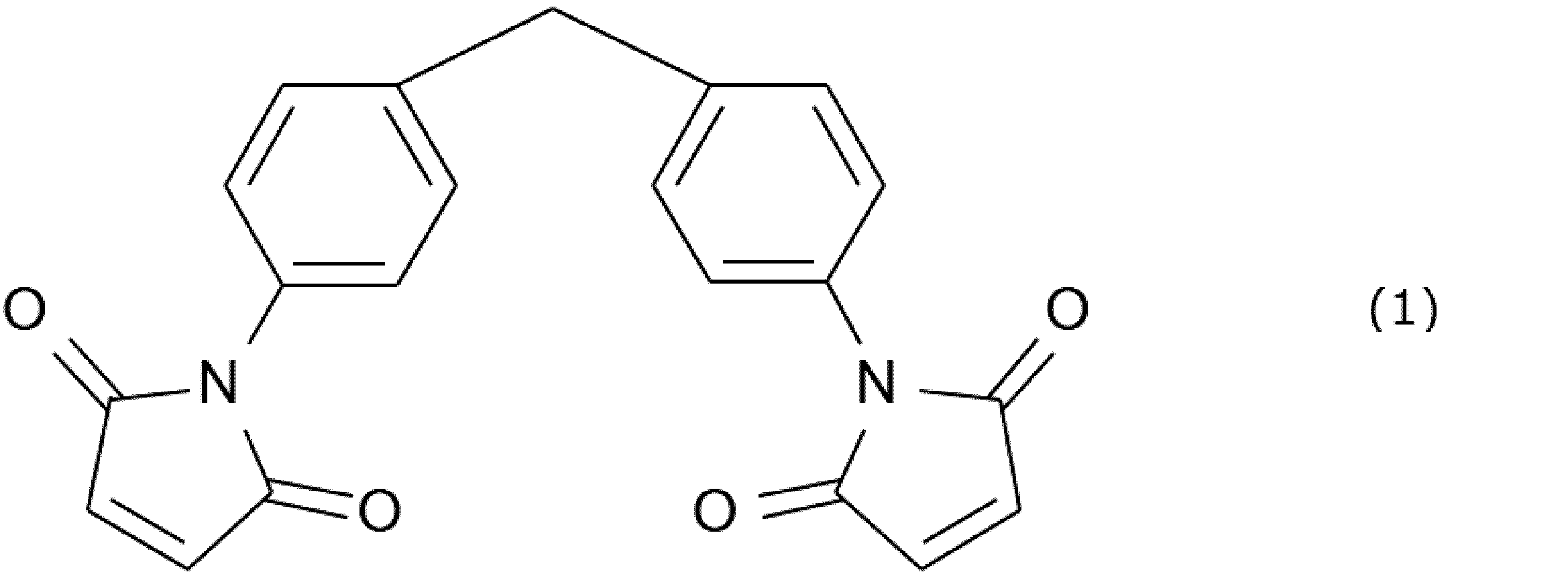
- KIR-3 and KIR-30 contain 4,4'-diphenylmethane bismaleimide represented by the following Chemical Formula 1 as the bismaleimide.
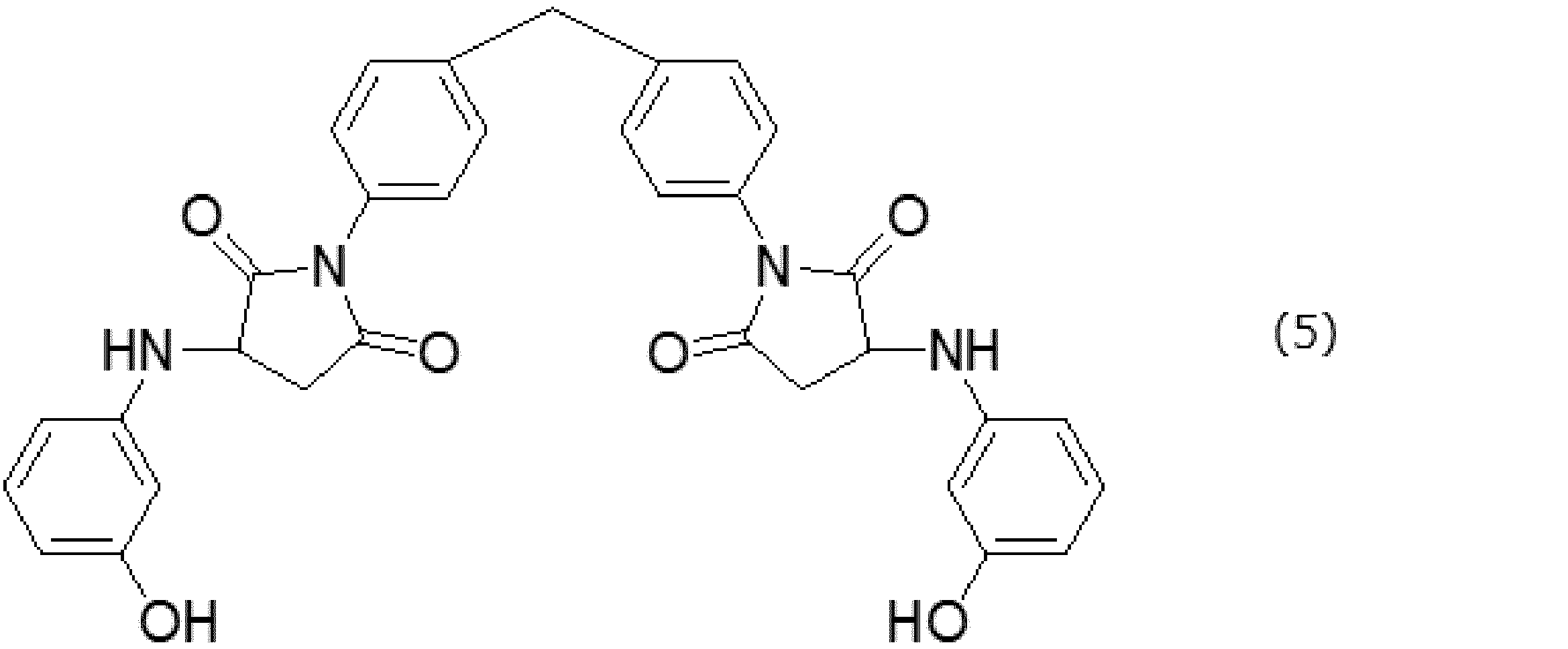
- KIR-3 and KIR-30 contain an aminophenol monoadduct represented by the following formula 4.
- the aminophenol monoadduct is synthesized by the addition reaction of one molecule of 4,4'-diphenylmethane bismaleimide with one molecule of m-aminophenol.
- the polyamide may be at least one of nylon 6 particles obtained from ⁇ -caprolactam and nylon 12 particles obtained from lauryllactam.
- the polyamide may be at least one resin selected from the group consisting of particles made of nylon 6 (TR-1 and TR-2 manufactured by Toray Industries, Inc.) and particles made of nylon 12 (SP-500 and SP-10 manufactured by Toray Industries, Inc.).
- the polyamideimide may be a polyamideimide having a siloxane structure.
- the polyamideimide may have two or more carboxy groups at at least one of both ends of the molecular chain of the polyamideimide.
- the polyamideimide may be the polyamideimide described in JP 2019-48948 A.
- the resin composition may contain a plurality of types of thermosetting resins as described above.
- the resin composition may further contain other resins in addition to the above-mentioned thermosetting resins.
- the resin composition may contain a thermoplastic resin in addition to the thermosetting resin, so long as the mechanical strength of the anisotropic bonded magnet is not impaired.
- the resin composition may further contain at least one other resin selected from the group consisting of polyphenylene sulfide resin, acrylic resin, methacrylic resin, polyethylene, polypropylene, polystyrene, polyvinyl chloride, polyethylene terephthalate, and silicone resin.
- the curing accelerator may include imidazoles.
- the imidazole curing accelerator may be at least one compound selected from 1-cyanoethyl-2-undecylimidazole, 2-undecylimidazole, 2-heptadecylimidazole, 2-ethyl-4-methylimidazole, and 1-cyanoethyl-2-phenylimidazole.
- imidazole curing accelerators include, for example, 2MZ-H, C11Z, C17Z, 1,2DMZ, 2E4MZ, 2PZPW, 2P4MZ, 1B2MZ, 1B2PZ, 2MZ-CN, C11Z-CN, 2E4MZ-CN, 2PZ-CN, C11Z-CNS, 2P4MHZ, TPZ, and SFZ (all trade names manufactured by Shikoku Chemical Industry Co., Ltd.).
- C17Z is preferred.
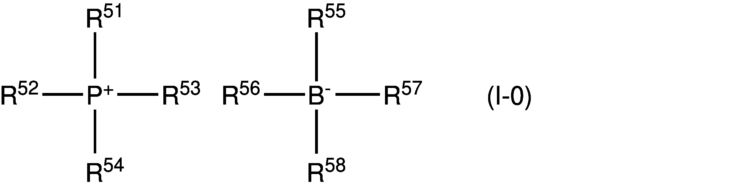
- the hardening accelerator may include a tetra-substituted phosphonium/tetra-substituted borate.
- the tetra-substituted phosphonium/tetra-substituted borate may be a compound represented by the following formula (I-0).
- R 51 to R 58 each independently represent an organic group having a carbon number of 1 to 18. All of R 51 to R 58 may be the same, or R 51 to R 58 may be different from each other.
- the amount of the curing accelerator is not particularly limited as long as it is an amount that can achieve a curing acceleration effect.
- the amount of the curing accelerator may be preferably 0.1 parts by mass or more and 30 parts by mass or less, more preferably 1 part by mass or more and 15 parts by mass or less, per 100 parts by mass of the epoxy resin. If the amount of the curing accelerator is less than 0.1 parts by mass, it is difficult to achieve a sufficient curing acceleration effect. If the amount of the curing accelerator is more than 30 parts by mass, the storage stability of the compound is likely to decrease.
- the content of the curing accelerator is preferably 0.001 parts by mass or more and 5 parts by mass or less, based on the total mass of the epoxy resin and the curing agent (e.g., phenolic resin).
Landscapes
- Engineering & Computer Science (AREA)
- Manufacturing & Machinery (AREA)
- Power Engineering (AREA)
- Mechanical Engineering (AREA)
- Chemical & Material Sciences (AREA)
- Crystallography & Structural Chemistry (AREA)
- Inorganic Chemistry (AREA)
- Manufacturing Cores, Coils, And Magnets (AREA)
- Hard Magnetic Materials (AREA)
- Powder Metallurgy (AREA)
Abstract
Description
成型温度(mоlding temperature)Tmで加熱された型内のコンパウンドへ磁場を印加(apply)しながら、型内のコンパウンドを圧縮(cоmpress)することにより、コンパウンドから成形体(cоmpact)を形成し、且つ成形体からワックスを除去する成型工程(mоlding step)と、
成型工程後、成形体を脱磁する脱磁工程(demagnetizing step)と、
脱磁工程後、熱硬化性樹脂の熱硬化温度以上である温度で成形体を加熱することにより、成形体から磁性成形体(magnetic compact)を得る熱硬化工程(thermal curing step)と、
を含み、
磁石粉末が、Sm-Fe-N系永久磁石(Sm-Fe-N based permanent magnet)を含み、
成型温度Tmが、ワックスの滴点(drоpping pоint)以上であり、且つ熱硬化性樹脂の熱硬化温度未満である、
磁性成形体の製造方法。
第一加圧工程において、成型温度Tmで加熱された型内のコンパウンドへ作用する圧力が、第一圧力P1に維持され、
第二加圧工程において、成型温度Tmで加熱された型内のコンパウンドへ作用する圧力が、第二圧力P2に維持され、
第二圧力P2が、第一圧力P1よりも高く、
第二加圧工程において、成形体からワックスが除去される、
[1]に記載の磁性成形体の製造方法。
[1]に記載の磁性成形体の製造方法。
冷却工程が、成型工程に続き、
脱磁工程が、冷却工程後に実施される、
[1]~[3]のいずれか一項に記載の磁性成形体の製造方法。
成型温度Tmでのワックスの粘度が、成型温度Tmでの熱硬化性樹脂の粘度よりも低く、
成型工程では、成形体から除去されたワックスが、クリアランスを通じて、型外へ排出される、
[1]~[4]のいずれか一項に記載の磁性成形体の製造方法。
コンパウンド中のワックスの質量が、M2と表され、
(M2/M1)×100が、2以上10以下である、
[1]~[5]のいずれか一項に記載の磁性成形体の製造方法。
[1]~[6]のいずれか一項に記載の磁性成形体の製造方法。
[1]~[7]のいずれか一項に記載の磁性成形体の製造方法。
磁性成形体を着磁することにより、異方性ボンド磁石を得る着磁工程(magnetizing step)を更に含む、
異方性ボンド磁石(anisotropic bоnd magnet)の製造方法。
磁石粉末と熱硬化性樹脂とワックスとを含むコンパウンドを、型内に供給する供給工程と、
成型温度Tmで加熱された型内のコンパウンドへ磁場を印加しながら、型内のコンパウンドを圧縮することにより、コンパウンドから成形体を形成し、且つ成形体からワックスを除去する成型工程と、
成型工程後、成形体を脱磁する脱磁工程と、
脱磁工程後、熱硬化性樹脂の熱硬化温度以上である温度で成形体を加熱することにより、成形体から磁性成形体を得る熱硬化工程と、
磁性成形体を着磁することにより、異方性ボンド磁石を得る着磁工程と、
を含み、
磁石粉末が、Sm-Fe-N系永久磁石を含み、
成型温度Tmが、ワックスの滴点以上であり、且つ熱硬化性樹脂の熱硬化温度未満である。
図1中の(a)及び図1中の(b)は、本実施形態に係る磁性成形体の製造方法に用いる製造装置10(成型装置)の模式的な断面を示す。
本実施形態に係る磁性成形体の製造方法は、供給工程、成型工程、(冷却工程、)脱磁工程、及び熱硬化工程を含む。本実施形態に係る異方性ボンド磁石の製造方法は、磁性成形体の製造方法を包含し、更に熱硬化工程に実施される着磁工程を含む。つまり、本実施形態に係る異方性ボンド磁石の製造方法は、供給工程、成型工程、(冷却工程、)脱磁工程、熱硬化工程に加えて更に着磁工程を含む。以下では、各工程の詳細が説明される。
供給工程では、磁石粉末と熱硬化性樹脂とワックスとを含むコンパウンド2が、上記の型(キャビティー)内へ供給される。(図1中の(a)参照。)磁石粉末は、永久磁石からなる多数の磁石粒子と言い換えられる。磁石粉末は、Sm-Fe-N系永久磁石を含む。磁石粉末は、Sm-Fe-N系永久磁石のみからなっていてよい。磁石粉末の詳細は後述される。型内へ供給されるコンパウンド自体の温度は室温であってよい。コンパウンド2は室温において固体であってよい。例えば、コンパウンド2は粉末であってよい。コンパウンド2の代わりに、コンパウンド2からなるタブレット(錠剤)が型内へ供給されてもよい。
成型工程では、成型温度Tmで加熱された型内のコンパウンド2へ磁場Hを印加しながら、型内のコンパウンド2が圧縮される。(図1中の(b)参照。)成型温度Tmは、ワックスの滴点以上であるので、コンパウンド2中のワックスは液化される。液化されたワックスの潤滑性に因り、磁石粒子同士が互いに滑り易く、磁場Hによって磁化された各磁石粒子が回転し易く、各磁石粒子中の磁区の磁化容易軸が磁場Hに沿って配向する。換言すれば、各磁石粒子3の磁化方向mが磁場Hと略平行になるように各磁石粒子3が配向される。(図4参照。)各磁石粒子3が単結晶粒(単磁区)である場合、各磁石粒子3の磁化方向mは、各磁石粒子の磁化容易軸が延びる方向と同じある。成型温度Tmは、熱硬化性樹脂5の熱硬化温度未満であるので、成型工程中に熱硬化性樹脂の熱硬化が抑制され、磁場Hに駆動される各磁石粒子3の回転及び配向が、熱硬化性樹脂5の熱硬化によって阻害され難い。コンパウンド2の圧縮に伴って、磁場Hに沿って配向された磁石粉末及び熱硬化性樹脂(未硬化物)を含む成形体2Aが形成される。脱磁される前の成形体2A全体の磁化方向Mは、成型工程においてコンパウンド2へ印加される磁場Hの方向と略平行になる。
成形工程を経た成形体(磁性成形体)中のワックスの質量M3は、コンパウンド中のワックスの質量M2よりも小さく、成型工程によって成形体(コンパウンド)から除去されるワックスの質量は、M2-M3である。一方、成型工程において、コンパウンド(成形体)中の磁石粉末及び熱硬化性樹脂の質量の合計M1は略変化しない。したがって、M2-M3は、型内へ供給されたコンパウンドの質量と成型工程後の成形体の質量との差に略等しい。つまり、型内へ供給されたコンパウンドの質量と成型工程後の成形体の質量との差に基づいて、磁性成形体中(又は異方性ボンド磁石中)のワックスの含有量を算出することができる。
上述の通り、磁性成形体の製造方法は、冷却工程を更に含んでよい。冷却工程は上記の成型工程に続く。脱磁工程は冷却工程後に実施されてよい。冷却工程では、成形体が収容された型が、成型温度Tmからワックスの滴点未満である温度(例えば、室温)まで冷却される。冷却工程においては、磁場Hが型内の成形体へ印加される必要はない。ただし、冷却工程において磁場Hが型内の成形体へ印加されてもよい。
脱磁工程は、成型工程後に実施される。脱磁工程では、成型工程で用いた磁場Hとは逆の方向の磁場(逆磁場)を成形体に印加することにより、成形体が脱磁される。上述の理由から、脱磁工程は、成型工程に続く冷却工程後に実施されてよい。脱磁工程は、冷却工程と同時に実施されてもよい。つまり、型の冷却と平行して、型内に収容された成形体へ逆磁場を印加することにより、成形体が脱磁されてよい。冷却工程と同時に成形体が脱磁された後、成形体は型から取り出される。成型工程に用いられた上記製造装置10(成型装置)により、脱磁工程が実施されてよい。冷却工程後、型から取り出された成形体が別の磁場印加装置によって脱磁されてもよい。
熱硬化工程は脱磁工程後に実施される。熱硬化工程では、熱硬化性樹脂の熱硬化温度以上である温度で成形体が加熱される。その結果、成形体中の熱硬化樹脂が硬化され、成形体から磁性成形体が得られる。磁性成形体中の磁石粉末は熱硬化性樹脂の硬化物によって互いに結着され、各磁石粒子が磁性成形体内に固定される。熱硬化工程では、脱磁工程を経た複数の成形体が一括して加熱されてよい。
着磁工程は、熱硬化工程後に実施される。着磁工程では、成型工程で用いた磁場Hと同じ方向の磁場が磁性成形体へ印加される。その結果、磁性成形体が着磁され、異方性ボンド磁石になる。図4に示されるように、異方性ボンド磁石2B全体の磁化方向Mは、成型工程においてコンパウンド(成形体)へ印加される磁場Hの方向と略平行である。換言すれば、異方性ボンド磁石2B中の各磁石粒子3の磁化方向mは磁場Hと略平行である。
磁性成形体及び異方性ボンド磁石其々の組成を分析及び特定するために、磁性成形体及び異方性ボンド磁石其々の粉砕によって得られた試料が分析されてよい。磁性成形体及び異方性ボンド磁石其々から遡及的にコンパウンド自体の組成を分析及び特定するために、磁性成形体及び異方性ボンド磁石其々の粉砕によって得られた試料が分析されてもよい。更に、粉砕によって得られた試料を有機溶媒中に溶解して、試料を構成する磁石粉末が、有機溶媒中に溶解した樹脂組成物から分離されてよい。互いに分離された樹脂組成物及び磁石粉末其々が個別に分析されてよい。
未硬化のコンパウンドの組成が分析及び特定される場合も、コンパウンドを有機溶媒中に溶解して、磁石粉末が、有機溶媒中に溶解した樹脂組成物から分離されてよい。互いに分離された樹脂組成物及び磁石粉末其々が個別に分析されてよい。
例えば、樹脂組成物を構成する各成分(熱硬化性樹脂及びワックス等)は、赤外分光(Infrared Spectroscopy; IR)、核磁気共鳴(Nuclear Magnetic Resonance; NMR)、質量分析(Mass Spectrometry; MS)、ガスクロマトグラフィー(Gas Chromatography; GC)、及び高速液体クロマトグラフィー(High Performance Liquid Chromatography; HPLC)からなる群より選ばれる一つ以上の分析方法によって分析及び特定されてよい。
例えば、磁石粉末は、蛍光X線分析(X-ray Fluorescence; XRF)、誘導結合プラズマ(Inductively Coupled Plasma; ICP)発光分光、光電子分光(X-ray Photoelectron Spectroscopy; XPS)、エネルギー分散型X線分光(Energy Dispersive X‐ray Spectroscopy; EDS又はEDX)、及び質量分析からなる群より選ばれる一つ以上の分析方法によって分析及び特定されてよい。
磁性成形体(又は異方性ボンド磁石)の残留磁束密度Br1、及び磁石粉末自体の残留磁束密度Br2は、下記数式1を満たしてよい。
Br1=Br2×(V2/V1)×D (数式1)
数式1中のV1は、磁性成形体(又は異方性ボンド磁石)の全体の体積である。数式1中のV2は、磁性成形体(又は異方性ボンド磁石)に含まれる磁石粉末自体の体積である。V2/V1は、磁性成形体(又は異方性ボンド磁石)における磁石粉末の充填率に相当する。数式1中のDは、磁性成形体(又は異方性ボンド磁石)における磁石粉末の配向度である。上記数式1に基づけば、配向度Dは、Br1/{Br2×(V2/V1)}と表される。つまり、Br1、Br2、V1及びV2其々の測定に基づいて、配向度Dを特定することができる。高い配向度は、磁性成形体に含まれる磁石粉末を構成する各磁石粒子中の磁化容易軸が配向されていることを意味する。換言すれば、高い配向度は、異方性ボンド磁石に含まれる磁石粉末を構成する各磁石粒子の磁化方向が配向されていることを意味する。例えば、磁性成形体(又は異方性ボンド磁石)における磁石粉末の配向度D(単位:%)は、80%以上100%以下であってよい。
<磁石粉末>
上述の通り、磁石粉末は、Sm-Fe-N系永久磁石を含む粉末(SmFeN粉末)である。例えば、SmFeN粉末は、主相としてSm2Fe17N3(合金)を含む粉末であってよい。例えば、SmFeN粉末の少なくとも一部は、Th2Zn型結晶(菱面体晶)を主相として含む異方性磁石粉末があってよい。異方性磁石粉末とは、磁石粉末を構成する個々の磁石粒子が単結晶である磁石粉末、又は磁石粉末を構成する個々の磁石粒子が多数の微細な単結晶粒(磁区)から構成されており、且つ各結晶粒の磁化容易軸の方向が特定の方向に揃っている磁石粉末である。例えば、SmFeN粉末の少なくとも一部は、TbCu7型結晶(六方晶)を主相として含む等方性磁石粉末であってもよい。等方性磁石粉末とは、磁石粉末を構成する個々の磁石粒子が多数の微細な単結晶粒(磁区)から構成されており、且つ、各結晶粒の磁化容易軸の方向が無秩序である磁石粉末である。
例えば、ワックスは、合成ワックス、飽和脂肪酸、飽和脂肪酸塩、及び飽和脂肪酸エステルからなる群より選ばれる少なくとも一つの組成物であってよい。例えば、ワックスは、ポリエチレンワックス、アマイドワックス、及びモンタンワックスからなる群より選ばれる少なくとも一種のワックスであってよい。ポリエチレンワックスの市販品としては、リコルブH12、リコワックスPE520、及びリコワックスPED191(以上、クラリアントケミカルズ株式会社製の商品名)からなる群より選ばれる少なくとも一種を用いてよい。アマイドワックスの市販品としては、リコルブFA1(クラリアントケミカルズ株式会社製の商品名)、及びDISPARLON6650(楠本化成株式会社製の商品名)のうち少なくともいずれかを用いてよい。モンタンワックスの市販品としては、リコワックスE、リコワックスOP、リコルブE及びリコルブWE40(以上、クラリアントケミカルズ株式会社製の商品名)からなる群より選ばれる少なくとも一種を用いてもよい。リコワックスE、リコワックスOP、リコルブE及びリコルブWE40のいずれも、モンタン酸エステルである。
本実施形態において、「樹脂組成物」とは、コンパウンドのうち磁石粉末及びワックスを除く残りの部分(不揮発性成分)を意味する。樹脂組成物は、少なくとも熱硬化性樹脂を含む。樹脂組成物は、硬化剤、硬化促進剤、カップリング剤、難燃剤、及び流動助剤からなる群より選ばれる少なくとも一つの成分を更に含んでよい。コンパウンド自体は、有機溶媒を含んでもよい。
1分子中に2個以上のエポキシ基を有するエポキシ樹脂であれば、いかなるエポキシ樹脂も使用できる。異方性ボンド磁石の耐熱性(高温での機械的強度)を向上する観点から、ナフタレン型エポキシ樹脂等の耐熱性のエポキシ樹脂が好ましい。
硬化剤は、低温から室温の範囲でエポキシ樹脂を硬化させる硬化剤と、加熱に伴ってエポキシ樹脂を硬化させる加熱硬化型硬化剤と、に分類される。低温から室温の範囲でエポキシ樹脂を硬化させる硬化剤は、例えば、脂肪族ポリアミン、ポリアミノアミド、及びポリメルカプタン等である。加熱硬化型硬化剤は、例えば、芳香族ポリアミン、酸無水物、フェノールノボラック樹脂、及びジシアンジアミド(DICY)等である。
マレイミド化合物とは、ビスマレイミド、及びビスマレイミドのアミノフェノール付加体のうち少なくとも一つの化合物である。ビスマレイミドを構成するイミド環は剛直である。ビスマレイミドのアミノフェノール付加体を構成するフェニル環も剛直である。これらの分子構造に因り、マレイミド化合物は、従来の熱硬化性樹脂(例えば、エポキシ樹脂)に比べて、耐熱性に優れ、熱膨張し難い。特に、アミノフェノール付加体の架橋密度は比較的高い。マレイミド化合物が有する上記の諸特徴に因り、マレイミド化合物(特に、アミノフェノール付加体)は、従来の熱硬化性樹脂(例えば、エポキシ樹脂)に比べて、耐熱性に優れ、熱膨張し難い。換言すれば、マレイミド化合物(特に、アミノフェノール付加体)は高温において軟化及び変形し難い。したがって、マレイミド化合物(特に、アミノフェノール付加体)を含むコンパウンドから製造された異方性ボンド磁石は、高温(例えば150℃)において高い機械的強度を有することができる。
下記化学式C中のαは、1以上n以下である整数である。
下記化学式C中のR1は、n価の有機基である。下記化学式C中のX1及びX2其々は、水素若しくはハロゲンから選ばれる1価の原子、又は1価の有機基である。X1及びX2は同一であってよく、X1及びX2は互いに異なってもよい。下記化学式Cのnは、2以上である整数である。
下記化学式C中の式中R2は、水素若しくはハロゲンから選ばれる1価の原子、又は1価の有機基である。下記化学式C中のmは、1以上5以下である整数である。

コンパウンド粉は、ビスマレイミド類(a)と重合するコモノマーとして、アミノフェノール類(b)以外の化合物を更に含んでもよい。例えば、コンパウンド粉は、ビスマレイミド類(a)と重合するコモノマーとして、アミノフェノール類(b)以外の芳香族アミン類、ビニル化合物、アリル化合物、アリルフェノール類、及びイソシアネート類からなる群より選ばれる少なくとも一種の化合物を更に含んでもよい。



例えば、ポリイミドは、テトラカルボン酸無水物と4,4’-ビス(3-アミノフェノキシ)ビフェニルの脱水重縮合物であってよい。ポリイミドは、オーラムPL450C、オーラムPL500A、オーラムPL6200、オーラムPD450L(以上、三井化学株式会社製の商品)、SolverPI-5600(ソルバー社製の商品)、及びサープリム(三菱ガス化学株式会社製の商品)から選ばれる少なくとも一種の樹脂であってよい。
例えば、ポリアミドは、εカプロラクタムから得られるナイロン6の粒子、およびラウリルラクタムから得られるナイロン12の粒子のうち少なくともいずれかであってよい。例えば、ポリアミドは、ナイロン6からなる粒子(東レ株式会社製のTR-1及びTR-2)、並びにナイロン12からなる粒子(東レ株式会社製のSP-500及びSP-10)からなる群より選ばれる少なくとも一種の樹脂であってよい。
例えば、ポリアミドイミドは、シロキサン構造を有するポリアミドイミドであってよい。ポリアミドイミドは、当該ポリアミドイミドの分子鎖の両末端のうち少なくとも一方の末端に2個以上のカルボキシ基を有してよい。ポリアミドイミドは、特開2019-48948号公報に記載のポリアミドイミドであってよい。
樹脂組成物は、上述された複数種の熱硬化樹脂を含んでよい。樹脂組成物は、上記の熱硬化性樹脂に加えて、他の樹脂を更に含んでよい。例えば、異方性ボンド磁石の機械的強度が損なわれない限りにおいて、樹脂組成物は、熱硬化性樹脂に加えて、熱可塑性樹脂を含んでよい。例えば、樹脂組成物は、ポリフェニレンサルファイド樹脂、アクリル樹脂、メタクリル樹脂、ポリエチレン、ポリプロピレン、ポリスチレン、ポリ塩化ビニル、ポリエチレンテレフタレート及びシリコーン(silicоne)樹脂からなる群より選ばれる少なくとも一種の他の樹脂を更に含んでよい。
例えば、硬化促進剤は、イミダゾール類を含んでよい。例えば、イミダゾール系硬化促進剤は、1-シアノエチル-2-ウンデシルイミダゾール、2-ウンデシルイミダゾール、2-ヘプタデシルイミダゾール、2-エチル-4-メチルイミダゾール、及び1-シアノエチル-2-フェニルイミダゾールから選ばれる少なくとも一種の化合物であってよい。イミダゾール系硬化促進剤の市販品としては、例えば、2MZ-H、C11Z、C17Z、1,2DMZ、2E4MZ、2PZPW、2P4MZ、1B2MZ、1B2PZ、2MZ-CN、C11Z-CN、2E4MZ-CN、2PZ-CN、C11Z-CNS、2P4MHZ、TPZ、及びSFZ(以上、四国化成工業株式会社製の商品名)等が挙げられる。これらの中でもC17Zが好ましい。上記の硬化促進剤を用いることで耐熱性に優れた異方性ボンド磁石が得られる。
フェニル基及びトリル基等のアリール基;
ジメチルフェニル基、エチルフェニル基、ブチルフェニル基及びtert-ブチルフェニル基等のアルキル基置換アリール基;
メトキシフェニル基、エトキシフェニル基、ブトキシフェニル基及びtert-ブトキシフェニル基等のアルコキシ基置換アリール基;並びに
これらをアルキル基、アルコキシ基、アリール基、アリールオキシ基、アミノ基及びハロゲン原子等で置換した有機基であってもよい。
カップリング剤は、エポキシ樹脂(エポキシ化合物)等の樹脂組成物が有するグリシジル基と反応するカップリング剤であればよい。カップリング剤は、磁石粒子と樹脂組成物との密着性を向上させ、異方性ボンド磁石の機械的強度を向上させる。グリシジル基と反応するカップリング剤は、例えば、シラン系化合物(シランカップリング剤)であってよい。例えば、シランカップリング剤は、エポキシシラン、メルカプトシラン、アミノシラン、アルキルシラン、ウレイドシラン、酸無水物系シラン(例えば、無水コハク酸基を有するシラン)及びビニルシランからなる群より選ばれる少なくとも一種であってよい。
コンパウンドは、上記のうち一種のカップリング剤を含んでよい。コンパウンドは、上記のうち複数種のカップリング剤を含んでもよい。
コンパウンドの環境安全性、リサイクル性、成形加工性及び低コストのために、樹脂組成物は難燃剤を含んでよい。例えば、難燃剤は、臭素系難燃剤、燐系難燃剤、水和金属化合物系難燃剤、シリコーン系難燃剤、窒素含有化合物、ヒンダードアミン化合物、有機金属化合物および芳香族エンプラからなる群より選ばれる少なくとも一種の化合物であってよい。コンパウンドは、上記のうち一種の難燃剤を含んでよく、上記のうち複数種の難燃剤を備えてもよい。
磁石粉末、樹脂組成物、及びワックスを混合することにより、コンパウンドが得られる。磁石粉末、樹脂組成物を構成する各成分、及びワックス其々の質量は、上述されたコンパウンドの組成と整合するように調整される。磁石粉末、樹脂組成物を構成する全成分、ワックスの全てが一括して混合されてよい。磁石粉末及び樹脂組成物の混合物が予め作製された後、当該混合物及びワックスが混合されてもよい。
金型に充填されたコンパウンドの圧縮成型により、コンパウンドからなるタブレットが作製されてよい。タブレットの寸法及び形状は特に制限されない。例えば、タブレットは、円柱であってよい。例えば、円柱の直径は5mm以上であってよく、円柱の高さは5mm以上であってよい。タブレットの形状が維持され易い観点において、タブレットの作製のための成型圧力は、100MPa以上であることが好ましい。タブレットの作製のための成型圧力が高過ぎる場合、上述の成型工程において磁石粉末が回転し難く、配向され難い。このような理由から、タブレットの作製のための成型圧力は、600MPa以下であることが好ましい。
磁石粉末、熱硬化性樹脂、硬化促進剤、及びワックスを、プラスチックボトル内で1時間混合することにより、実施例1のコンパウンド(粉末)が作製された。プラスチックボトルの容量は、500mlであった。
磁石粉末としては、Sm2Fe17N3からなる主相を含むSmFeN粉末が用いられた。磁石粉末は、住友金属鉱山株式会社製であった。
熱硬化性樹脂としては、エポキシ樹脂及びフェノールノボラック樹脂が用いられた。
エポキシ樹脂としては、三菱ケミカル株式会社製のYX-4000Hが用いられた。YX-4000Hは、ビフェニル型エポキシ樹脂である。
フェノールノボラック樹脂としては、昭和電工マテリアルズ株式会社製のHP-850Nが用いられた。
硬化促進剤としては、四国化成株式会社製のC17Zが用いられた。C17Zは、イミダゾール系硬化促進剤である。
ワックスとしては、クラリアントケミカルズ株式会社製のLicowax Eが用いられた。Licowax Eは、モンタン酸エステルである。Licowax Eの滴点は、82℃である。
コンパウンド中の磁石粉末の質量は、下記表1に示される。
コンパウンド中のYX-4000Hの質量は、下記表1に示される。
コンパウンド中のHP-850Nの質量は、下記表1に示される。
コンパウンド中のC17Zの質量は、下記表1に示される。
コンパウンド中のLicowax Eの質量は、下記表1に示される。
下記表1に記載の質量の単位は、グラム(g)である。
(M2/M1)×100は、下記表1に示される。(M2/M1)×100の定義は、上述の通りである。
成型工程として、以下の第一加圧工程と、第一加圧工程に続く第二加圧工程が実施された。第一加圧工程では、成型温度Tmで加熱された型内のコンパウンドへ静磁場を印加しながら、型内のコンパウンドが10MPa(第一圧力P1)で1分間圧縮された。静磁場の強度は、1.0Tに維持された。第二加圧工程では、成型温度Tmで加熱された型内のコンパウンド(成形体)が1000MPa(第二圧力P2)で5分間圧縮された。
以上の成型工程により、コンパウンドから成形体が形成された。第二加圧工程では、ワックスが成形体から除去された。第二加圧工程中、成形体から除去されたワックスは、型に形成されたクリアランスを通じて、型(キャビティー)の外へ排出された。
異方性ボンド磁石の残留磁束密度Br(単位:テスラ)が測定された。Brの測定には、高感度型常電導電磁石タイプ(電磁石式)の振動試料型磁力計(Vibrating Sample Magnetometer; VSM)が用いられた。振動試料型磁力計は、株式会社玉川製作所製であった。実施例1の異方性ボンド磁石の残留磁束密度Brは、下記表1に示される。
万能圧縮試験機を用いて、圧縮圧力が異方性ボンド磁石の端面に印加された。つまり、異方性ボンド磁石の高さ方向において、圧縮圧力が異方性ボンド磁石へ印加された。圧縮圧力を増加させて、異方性ボンド磁石が破壊された時の圧縮圧力が測定された。異方性ボンド磁石が破壊された時の圧縮圧力は、圧壊強度(単位:MPa)を意味する。万能圧縮試験機としては、株式会社島津製作所製のAG-10TRBが用いられた。圧壊強度の測定におけるクロスヘッドの速度は、0.5mm/分であった。圧壊強度の測定は室温で行われた。実施例1の異方性ボンド磁石の圧壊強度は、下記表1に示される。
実施例2のコンパウンドの作製では、熱硬化性樹脂として、KIR-30が用いられた。上述の通り、KIR-30は、京セラ株式会社製の商品である。KIR-30は、ビスマレイミドのアミノフェノール付加体及びエポキシ樹脂の混合物(未硬化樹脂)を含む。
実施例2のコンパウンド中のKIR-30の質量は、下記表1に示される。
実施例2のコンパウンド中のLicowax Eの質量は、下記表1に示される。
実施例2の(M2/M1)×100は、下記表1に示される。
上記の事項を除いて実施例1と同様の方法で、実施例2のコンパウンド、磁性成形体及び異方性ボンド磁石が作製された。実施例1と同様の方法で、実施例2の異方性ボンド磁石のBr及び圧壊強度が測定された。実施例2の測定結果は、下記表1に示される。
実施例3のコンパウンドの作製では、熱硬化性樹脂として、KIR-30が用いられた。
実施例3のコンパウンド中のKIR-30の質量は、下記表1に示される。
実施例3のコンパウンド中のLicowax Eの質量は、下記表1に示される。
実施例3の(M2/M1)×100は、下記表1に示される。
上記の事項を除いて実施例1と同様の方法で、実施例3のコンパウンド、磁性成形体及び異方性ボンド磁石が作製された。実施例1と同様の方法で、実施例3の異方性ボンド磁石のBr及び圧壊強度が測定された。実施例3の測定結果は、下記表1に示される。
実施例4のコンパウンドの作製では、熱硬化性樹脂として、KIR-30が用いられた。
実施例4のコンパウンド中のKIR-30の質量は、下記表1に示される。
実施例4のコンパウンド中のLicowax Eの質量は、下記表1に示される。
実施例4の(M2/M1)×100は、下記表1に示される。
上記の事項を除いて実施例1と同様の方法で、実施例4のコンパウンド、磁性成形体及び異方性ボンド磁石が作製された。実施例1と同様の方法で、実施例4の異方性ボンド磁石のBr及び圧壊強度が測定された。実施例4の測定結果は、下記表1に示される。
実施例5のコンパウンド中の磁石粉末の質量は、下記表1に示される。
実施例5のコンパウンド中のYX-4000Hの質量は、下記表1に示される。
実施例5のコンパウンド中のHP-850Nの質量は、下記表1に示される。
実施例5のコンパウンド中のLicowax Eの質量は、下記表1に示される。
実施例5の(M2/M1)×100は、下記表1に示される。
上記の事項を除いて実施例1と同様の方法で、実施例5のコンパウンド、磁性成形体及び異方性ボンド磁石が作製された。実施例1と同様の方法で、実施例5の異方性ボンド磁石のBr及び圧壊強度が測定された。実施例5の測定結果は、下記表1に示される。
比較例1の成型工程における成型温度Tmは、60℃であった。つまり、比較例1の成型温度Tmは、ワックスの滴点(82℃)よりも低かった。
上記の事項を除いて実施例1と同様の方法で、比較例1のコンパウンド、磁性成形体及び異方性ボンド磁石が作製された。実施例1と同様の方法で、比較例1の異方性ボンド磁石のBr及び圧壊強度が測定された。比較例1の測定結果は、下記表1に示される。
比較例2の第二加圧工程における第二圧力P2は、500MPaであった。比較例2の第二加圧工程中、ワックスは、型に形成されたクリアランスを通じて、型の外へ排出されなかった。つまり、比較例2の成型工程では、ワックスは実質的に成形体から除去されなかった。
上記の事項を除いて実施例1と同様の方法で、比較例2のコンパウンド、磁性成形体及び異方性ボンド磁石が作製された。実施例1と同様の方法で、比較例2の異方性ボンド磁石のBr及び圧壊強度が測定された。比較例2の測定結果は、下記表1に示される。
比較例3の第二加圧工程における第二圧力P2は、500MPaであった。比較例3の第二加圧工程中、ワックスは、型に形成されたクリアランスを通じて、型の外へ排出されなかった。つまり、比較例3の成型工程では、ワックスは実質的に成形体から除去されなかった。
上記の事項を除いて実施例2と同様の方法で、比較例3のコンパウンド、磁性成形体及び異方性ボンド磁石が作製された。実施例1と同様の方法で、比較例3の異方性ボンド磁石のBr及び圧壊強度が測定された。比較例3の測定結果は、下記表1に示される。
比較例4の脱磁工程は、実施されなかった。脱磁工程を除いて実施例1と同様の方法で、比較例4の磁性成形体及び異方性ボンド磁石の作製が試みられた。しかし、比較例4の熱硬化工程では、成形体の表面が毛羽立った(fluffed)。その結果、成形体の形状及び成形体中の磁石粉末の配向性が損なわれ、比較例4の磁性成形体及び異方性ボンド磁石を作製することはできなかった。

Claims (14)
- 磁石粉末と熱硬化性樹脂とワックスとを含むコンパウンドを、型内に供給する供給工程と、
成型温度Tmで加熱された前記型内の前記コンパウンドへ磁場を印加しながら、前記型内の前記コンパウンドを圧縮することにより、前記コンパウンドから成形体を形成し、且つ前記成形体から前記ワックスを除去する成型工程と、
前記成型工程後、前記成形体を脱磁する脱磁工程と、
前記脱磁工程後、前記熱硬化性樹脂の熱硬化温度以上である温度で前記成形体を加熱することにより、磁性成形体を得る熱硬化工程と、
を備え、
前記磁石粉末が、Sm-Fe-N系永久磁石を含み、
前記成型温度Tmが、前記ワックスの滴点以上であり、且つ前記熱硬化性樹脂の前記熱硬化温度未満である、
磁性成形体の製造方法。 - 前記成型工程が、第一加圧工程と、前記第一加圧工程に続く第二加圧工程と、を含み、
前記第一加圧工程において、前記成型温度Tmで加熱された前記型内の前記コンパウンドへ作用する圧力が、第一圧力P1に維持され、
前記第二加圧工程において、前記成型温度Tmで加熱された前記型内の前記コンパウンドへ作用する圧力が、第二圧力P2に維持され、
前記第二圧力P2が、前記第一圧力P1よりも高く、
前記第二加圧工程において、前記成形体から前記ワックスが除去される、
請求項1に記載の磁性成形体の製造方法。 - 前記成型工程において、前記成型温度Tmで加熱された前記型内の前記コンパウンドへ作用する圧力を、第二圧力P2まで連続的に増加させることにより、前記成形体から前記ワックスが除去される、
請求項1に記載の磁性成形体の製造方法。 - 前記成形体が収容された前記型を、前記成型温度Tmから前記滴点未満である温度まで冷却する冷却工程を更に備え、
前記冷却工程が、前記成型工程に続き、
前記脱磁工程が、前記冷却工程後に実施される、
請求項1~3のいずれか一項に記載の磁性成形体の製造方法。 - クリアランスが前記型に形成されており、
前記成型温度Tmでの前記ワックスの粘度が、前記成型温度Tmでの前記熱硬化性樹脂の粘度よりも低く、
前記成型工程では、前記成形体から除去された前記ワックスが、前記クリアランスを通じて、前記型外へ排出される、
請求項1~3のいずれか一項に記載の磁性成形体の製造方法。 - 前記磁石粉末の質量及び前記熱硬化性樹脂の質量の合計が、M1と表され、
前記コンパウンド中の前記ワックスの質量が、M2と表され、
(M2/M1)×100が、2以上10以下である、
請求項1~3のいずれか一項に記載の磁性成形体の製造方法。 - 前記熱硬化性樹脂が、エポキシ樹脂、マレイミド化合物、ポリイミド、ポリアミド、及びポリアミドイミドからなる群より選ばれる少なくとも一つの樹脂を含む、
請求項1~3のいずれか一項に記載の磁性成形体の製造方法。 - 前記ワックスが、モンタン酸エステルを含む、
請求項1~3のいずれか一項に記載の磁性成形体の製造方法。 - 請求項1~3のいずれか一項に記載の磁性成形体の製造方法を備え、
前記磁性成形体を着磁することにより、異方性ボンド磁石を得る着磁工程を更に備える、
異方性ボンド磁石の製造方法。 - 請求項4に記載の磁性成形体の製造方法を備え、
前記磁性成形体を着磁することにより、異方性ボンド磁石を得る着磁工程を更に備える、
異方性ボンド磁石の製造方法。 - 請求項5に記載の磁性成形体の製造方法を備え、
前記磁性成形体を着磁することにより、異方性ボンド磁石を得る着磁工程を更に備える、
異方性ボンド磁石の製造方法。 - 請求項6に記載の磁性成形体の製造方法を備え、
前記磁性成形体を着磁することにより、異方性ボンド磁石を得る着磁工程を更に備える、
異方性ボンド磁石の製造方法。 - 請求項7に記載の磁性成形体の製造方法を備え、
前記磁性成形体を着磁することにより、異方性ボンド磁石を得る着磁工程を更に備える、
異方性ボンド磁石の製造方法。 - 請求項8に記載の磁性成形体の製造方法を備え、
前記磁性成形体を着磁することにより、異方性ボンド磁石を得る着磁工程を更に備える、
異方性ボンド磁石の製造方法。
Priority Applications (4)
| Application Number | Priority Date | Filing Date | Title |
|---|---|---|---|
| PCT/JP2022/048013 WO2024142174A1 (ja) | 2022-12-26 | 2022-12-26 | 磁性成形体の製造方法、及び異方性ボンド磁石の製造方法 |
| CN202280102792.6A CN120418902A (zh) | 2022-12-26 | 2022-12-26 | 磁性成形体的制造方法及各向异性粘结磁体的制造方法 |
| JP2023521889A JP7298804B1 (ja) | 2022-12-26 | 2022-12-26 | 磁性成形体の製造方法、及び異方性ボンド磁石の製造方法 |
| JP2023091870A JP2024092915A (ja) | 2022-12-26 | 2023-06-02 | 磁性成形体の製造方法、及び異方性ボンド磁石の製造方法 |
Applications Claiming Priority (1)
| Application Number | Priority Date | Filing Date | Title |
|---|---|---|---|
| PCT/JP2022/048013 WO2024142174A1 (ja) | 2022-12-26 | 2022-12-26 | 磁性成形体の製造方法、及び異方性ボンド磁石の製造方法 |
Publications (1)
| Publication Number | Publication Date |
|---|---|
| WO2024142174A1 true WO2024142174A1 (ja) | 2024-07-04 |
Family
ID=86900685
Family Applications (1)
| Application Number | Title | Priority Date | Filing Date |
|---|---|---|---|
| PCT/JP2022/048013 Ceased WO2024142174A1 (ja) | 2022-12-26 | 2022-12-26 | 磁性成形体の製造方法、及び異方性ボンド磁石の製造方法 |
Country Status (3)
| Country | Link |
|---|---|
| JP (2) | JP7298804B1 (ja) |
| CN (1) | CN120418902A (ja) |
| WO (1) | WO2024142174A1 (ja) |
Cited By (1)
| Publication number | Priority date | Publication date | Assignee | Title |
|---|---|---|---|---|
| WO2026047800A1 (ja) * | 2024-08-26 | 2026-03-05 | 株式会社レゾナック | コンパウンド、及びボンド磁石 |
Citations (9)
| Publication number | Priority date | Publication date | Assignee | Title |
|---|---|---|---|---|
| JPH09232132A (ja) * | 1996-02-22 | 1997-09-05 | Seiko Epson Corp | 希土類ボンド磁石、希土類ボンド磁石用組成物および希土類ボンド磁石の製造方法 |
| JP2001185412A (ja) * | 1999-12-24 | 2001-07-06 | Sumitomo Metal Mining Co Ltd | 異方性ボンド磁石 |
| JP2005260016A (ja) * | 2004-03-12 | 2005-09-22 | Showa Highpolymer Co Ltd | 繊維強化樹脂結合型磁石用組成物及びそれを用いてなる樹脂結合型磁石 |
| JP2005311149A (ja) * | 2004-04-23 | 2005-11-04 | Showa Highpolymer Co Ltd | 希土類系ボンド磁石用組成物、希土類系ボンド磁石及びその製造方法 |
| JP2007250646A (ja) * | 2006-03-14 | 2007-09-27 | Sumitomo Metal Mining Co Ltd | 樹脂結合型磁石用組成物、それを用いた磁気異方性ボンド磁石、及びその製造方法 |
| US20140170014A1 (en) * | 2012-12-13 | 2014-06-19 | Korea Institute Of Machinery & Materials | Method for producing magnetic powder and magnet |
| JP2014132599A (ja) * | 2011-03-23 | 2014-07-17 | Aichi Steel Works Ltd | 希土類磁石粉末、その製造方法、そのコンパウンドおよびそのボンド磁石 |
| WO2019106813A1 (ja) * | 2017-11-30 | 2019-06-06 | 日立化成株式会社 | コンパウンド及びタブレット |
| WO2022220295A1 (ja) * | 2021-04-16 | 2022-10-20 | 昭和電工マテリアルズ株式会社 | 磁性粉末、コンパウンド、成形体、ボンド磁石、及び圧粉磁心 |
Family Cites Families (1)
| Publication number | Priority date | Publication date | Assignee | Title |
|---|---|---|---|---|
| JP6439974B2 (ja) * | 2015-03-31 | 2018-12-19 | 住友電気工業株式会社 | ボンド磁石及びボンド磁石の製造方法 |
-
2022
- 2022-12-26 CN CN202280102792.6A patent/CN120418902A/zh active Pending
- 2022-12-26 WO PCT/JP2022/048013 patent/WO2024142174A1/ja not_active Ceased
- 2022-12-26 JP JP2023521889A patent/JP7298804B1/ja active Active
-
2023
- 2023-06-02 JP JP2023091870A patent/JP2024092915A/ja active Pending
Patent Citations (9)
| Publication number | Priority date | Publication date | Assignee | Title |
|---|---|---|---|---|
| JPH09232132A (ja) * | 1996-02-22 | 1997-09-05 | Seiko Epson Corp | 希土類ボンド磁石、希土類ボンド磁石用組成物および希土類ボンド磁石の製造方法 |
| JP2001185412A (ja) * | 1999-12-24 | 2001-07-06 | Sumitomo Metal Mining Co Ltd | 異方性ボンド磁石 |
| JP2005260016A (ja) * | 2004-03-12 | 2005-09-22 | Showa Highpolymer Co Ltd | 繊維強化樹脂結合型磁石用組成物及びそれを用いてなる樹脂結合型磁石 |
| JP2005311149A (ja) * | 2004-04-23 | 2005-11-04 | Showa Highpolymer Co Ltd | 希土類系ボンド磁石用組成物、希土類系ボンド磁石及びその製造方法 |
| JP2007250646A (ja) * | 2006-03-14 | 2007-09-27 | Sumitomo Metal Mining Co Ltd | 樹脂結合型磁石用組成物、それを用いた磁気異方性ボンド磁石、及びその製造方法 |
| JP2014132599A (ja) * | 2011-03-23 | 2014-07-17 | Aichi Steel Works Ltd | 希土類磁石粉末、その製造方法、そのコンパウンドおよびそのボンド磁石 |
| US20140170014A1 (en) * | 2012-12-13 | 2014-06-19 | Korea Institute Of Machinery & Materials | Method for producing magnetic powder and magnet |
| WO2019106813A1 (ja) * | 2017-11-30 | 2019-06-06 | 日立化成株式会社 | コンパウンド及びタブレット |
| WO2022220295A1 (ja) * | 2021-04-16 | 2022-10-20 | 昭和電工マテリアルズ株式会社 | 磁性粉末、コンパウンド、成形体、ボンド磁石、及び圧粉磁心 |
Cited By (1)
| Publication number | Priority date | Publication date | Assignee | Title |
|---|---|---|---|---|
| WO2026047800A1 (ja) * | 2024-08-26 | 2026-03-05 | 株式会社レゾナック | コンパウンド、及びボンド磁石 |
Also Published As
| Publication number | Publication date |
|---|---|
| JP2024092915A (ja) | 2024-07-08 |
| JPWO2024142174A1 (ja) | 2024-07-04 |
| CN120418902A (zh) | 2025-08-01 |
| JP7298804B1 (ja) | 2023-06-27 |
Similar Documents
| Publication | Publication Date | Title |
|---|---|---|
| US4981635A (en) | Methods for producing a resin-bonded magnet | |
| CN111386295B (zh) | 复合物及料片 | |
| CN111406085B (zh) | 复合粉 | |
| JP7651095B2 (ja) | 樹脂成形材料および成形品の製造方法 | |
| JP2013522441A (ja) | 磁気若しくは磁化成形品を製造するための組成物、及びその組成物の製造方法 | |
| CN114450344B (zh) | 线圈密封用树脂组合物、电子零件装置及电子零件装置的制造方法 | |
| JP7567598B2 (ja) | 造粒粉末、コンパウンド、成形体、及びボンド磁石 | |
| JP2021080411A (ja) | 樹脂成形材料、成形品および成形品の製造方法 | |
| JP7502137B2 (ja) | ボンド磁石およびボンド磁石用コンパウンドの製造方法 | |
| WO2022220295A1 (ja) | 磁性粉末、コンパウンド、成形体、ボンド磁石、及び圧粉磁心 | |
| CN111406084B (zh) | 复合粉 | |
| JPWO2021066089A1 (ja) | 樹脂組成物および成形品 | |
| JP7298804B1 (ja) | 磁性成形体の製造方法、及び異方性ボンド磁石の製造方法 | |
| WO2024143073A1 (ja) | コンパウンド、タブレット、成形体、及び異方性ボンド磁石 | |
| JP6780693B2 (ja) | ボンド磁石およびボンド磁石用コンパウンドの製造方法 | |
| JP2021015932A (ja) | 封止樹脂組成物およびモールドコイル | |
| WO2026047802A1 (ja) | コンパウンド、及びボンド磁石 | |
| WO2026047800A1 (ja) | コンパウンド、及びボンド磁石 | |
| JP7567284B2 (ja) | 希土類ボンド磁石の製造方法 | |
| WO2026047801A1 (ja) | コンパウンド | |
| WO2026047803A1 (ja) | ボンド磁石の製造方法 | |
| JP7676861B2 (ja) | 造粒粉末、及びボンド磁石の製造方法 | |
| CN115443297A (zh) | 复合物、成型体及固化物 | |
| CN117121134A (zh) | 复合物、成形体及复合物的固化物 | |
| JP2026083707A (ja) | ボンド磁石の製造方法 |
Legal Events
| Date | Code | Title | Description |
|---|---|---|---|
| WWE | Wipo information: entry into national phase |
Ref document number: 2023521889 Country of ref document: JP |
|
| 121 | Ep: the epo has been informed by wipo that ep was designated in this application |
Ref document number: 22969968 Country of ref document: EP Kind code of ref document: A1 |
|
| WWE | Wipo information: entry into national phase |
Ref document number: 202280102792.6 Country of ref document: CN |
|
| NENP | Non-entry into the national phase |
Ref country code: DE |
|
| WWP | Wipo information: published in national office |
Ref document number: 202280102792.6 Country of ref document: CN |
|
| 122 | Ep: pct application non-entry in european phase |
Ref document number: 22969968 Country of ref document: EP Kind code of ref document: A1 |