WO2024134993A1 - 車載電子制御装置 - Google Patents
車載電子制御装置 Download PDFInfo
- Publication number
- WO2024134993A1 WO2024134993A1 PCT/JP2023/030998 JP2023030998W WO2024134993A1 WO 2024134993 A1 WO2024134993 A1 WO 2024134993A1 JP 2023030998 W JP2023030998 W JP 2023030998W WO 2024134993 A1 WO2024134993 A1 WO 2024134993A1
- Authority
- WO
- WIPO (PCT)
- Prior art keywords
- control device
- electronic control
- silicone resin
- vehicle electronic
- molar concentration
- Prior art date
- Legal status (The legal status is an assumption and is not a legal conclusion. Google has not performed a legal analysis and makes no representation as to the accuracy of the status listed.)
- Ceased
Links
Images

Classifications
-
- H—ELECTRICITY
- H10—SEMICONDUCTOR DEVICES; ELECTRIC SOLID-STATE DEVICES NOT OTHERWISE PROVIDED FOR
- H10W—GENERIC PACKAGES, INTERCONNECTIONS, CONNECTORS OR OTHER CONSTRUCTIONAL DETAILS OF DEVICES COVERED BY CLASS H10
- H10W40/00—Arrangements for thermal protection or thermal control
- H10W40/20—Arrangements for cooling
- H10W40/25—Arrangements for cooling characterised by their materials
- H10W40/251—Organics
-
- C—CHEMISTRY; METALLURGY
- C08—ORGANIC MACROMOLECULAR COMPOUNDS; THEIR PREPARATION OR CHEMICAL WORKING-UP; COMPOSITIONS BASED THEREON
- C08L—COMPOSITIONS OF MACROMOLECULAR COMPOUNDS
- C08L83/00—Compositions of macromolecular compounds obtained by reactions forming in the main chain of the macromolecule a linkage containing silicon with or without sulfur, nitrogen, oxygen or carbon only; Compositions of derivatives of such polymers
- C08L83/04—Polysiloxanes
-
- H—ELECTRICITY
- H10—SEMICONDUCTOR DEVICES; ELECTRIC SOLID-STATE DEVICES NOT OTHERWISE PROVIDED FOR
- H10W—GENERIC PACKAGES, INTERCONNECTIONS, CONNECTORS OR OTHER CONSTRUCTIONAL DETAILS OF DEVICES COVERED BY CLASS H10
- H10W40/00—Arrangements for thermal protection or thermal control
- H10W40/10—Arrangements for heating
-
- C—CHEMISTRY; METALLURGY
- C08—ORGANIC MACROMOLECULAR COMPOUNDS; THEIR PREPARATION OR CHEMICAL WORKING-UP; COMPOSITIONS BASED THEREON
- C08G—MACROMOLECULAR COMPOUNDS OBTAINED OTHERWISE THAN BY REACTIONS ONLY INVOLVING UNSATURATED CARBON-TO-CARBON BONDS
- C08G77/00—Macromolecular compounds obtained by reactions forming a linkage containing silicon with or without sulfur, nitrogen, oxygen or carbon in the main chain of the macromolecule
- C08G77/04—Polysiloxanes
- C08G77/12—Polysiloxanes containing silicon bound to hydrogen
-
- C—CHEMISTRY; METALLURGY
- C08—ORGANIC MACROMOLECULAR COMPOUNDS; THEIR PREPARATION OR CHEMICAL WORKING-UP; COMPOSITIONS BASED THEREON
- C08G—MACROMOLECULAR COMPOUNDS OBTAINED OTHERWISE THAN BY REACTIONS ONLY INVOLVING UNSATURATED CARBON-TO-CARBON BONDS
- C08G77/00—Macromolecular compounds obtained by reactions forming a linkage containing silicon with or without sulfur, nitrogen, oxygen or carbon in the main chain of the macromolecule
- C08G77/04—Polysiloxanes
- C08G77/20—Polysiloxanes containing silicon bound to unsaturated aliphatic groups
Definitions
- the present invention relates to an in-vehicle electronic control device that has a heat dissipation material interposed between the electronic components and the heat dissipation member.
- ADAS Advanced driver assistance systems
- AD autonomous driving
- ECUs electronice control units
- on-board ECUs the various ECUs installed in automobiles and other vehicles are collectively referred to as on-board ECUs.
- In-vehicle ECUs perform complex and advanced calculations, and generate a lot of heat from electronic components such as integrated circuits (ICs). To prevent thermal runaway, heat must be dissipated using heat dissipation materials such as heat sinks and heat spreaders. In this case, a heat dissipation material (also sometimes called a TIM, thermal conductive material, or thermal interface material) is often placed between the electronic components and the heat dissipation material to increase the efficiency of heat dissipation.
- a heat dissipation material also sometimes called a TIM, thermal conductive material, or thermal interface material
- Patent Document 1 JP 2018-198335 A describes a method for manufacturing an electronic control device including a housing formed by joining two components, a circuit board on which electronic components are mounted and housed in the housing, a waterproof sealant that seals the joints of the components, and a thermally conductive material that thermally connects the electronic components and the housing,
- the method for manufacturing an electronic control device is taught, in which a thermosetting material is used for the waterproof sealant and a material having the property of increasing viscosity when heated is used for the thermally conductive material, the circuit board and the thermally conductive material are contained within a housing, and the housing is heated with the waterproof sealant before hardening placed at the joints of each of the components, and the heating process hardens the waterproof sealant and increases the viscosity of the thermally conductive material.
- thermosetting heat dissipation grease as a heat dissipation material can improve the ease of application, and then by thermally curing the heat dissipation grease, it is possible to provide an electronic control device that can suppress deformation or loss of shape due to thermal deformation or vibration.
- Patent Document 1 requires heat treatment, and the emission of CO2 gas caused by the heat treatment is an obstacle to achieving carbon neutrality.
- the heat treatment itself is performed using electricity, it is necessary to consider the CO2 gas generated when generating the electricity.
- thermosetting TIM As part of efforts to become carbon neutral, the inventors investigated replacing conventional thermosetting TIM with room temperature curing TIM to eliminate the need for heat treatment in the manufacture of automotive ECUs.
- room temperature curing TIM does not require heat treatment, the curing time is strongly affected by the temperature of the working environment.
- the working environment temperature varies depending on the season and region, but is expected to drop to a minimum of around 15°C.
- the inventors investigated the curing time of room temperature curing TIM at 15°C. As a result, they found that conventional two-part mixture room temperature curing TIM takes approximately 72 hours to cure at 15°C, which creates other problems in the form of increased work time and reduced throughput (resulting in increased costs) in the manufacture of on-board ECUs.
- the object of the present invention is to provide an in-vehicle ECU that uses a room temperature curing TIM that has a curing time of 40 hours or less at 15°C.
- One aspect of the present invention is an in-vehicle electronic control device having a predetermined heat dissipation material interposed between an electronic component and a heat dissipation member, the predetermined heat dissipation material is a material having a silicone resin as a matrix,
- the present invention allows the following improvements and modifications to be freely combined with the on-vehicle electronic control device according to the present invention.
- the silicone resin has a storage modulus of more than 0.1 MPa.
- the silicone resin has a storage modulus of 0.15 MPa or more.
- the silicone resin has a storage modulus of 0.2 MPa or more.
- the silicone resin has a tensile shear adhesive strength of 0.015 MPa or more.
- the silicone resin has a tensile shear bond strength of 0.020 MPa or more.
- the silicone resin has a tensile shear bond strength of 0.025 MPa or more.
- the silicone resin is a two-liquid mixture addition reaction type room temperature curable silicone resin.
- the present invention by using a room temperature curing TIM that has a curing time of 40 hours or less even when the working environment temperature is 15°C, it is possible to provide an in-vehicle ECU that contributes to carbon neutrality without significantly sacrificing productivity (e.g., throughput). Note that other issues, configurations, and effects will be made clear in the description of the embodiments described below.
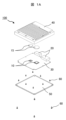
- FIG. 1 is an exploded perspective schematic view showing an example of an in-vehicle electronic control unit (in-vehicle ECU) according to the present invention
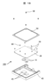
- FIG. 1B is a schematic exploded perspective view of the exploded perspective view shown in FIG. 1A as viewed from the top-bottom opposite side.
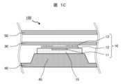
- FIG. 2 is a schematic cross-sectional view of a portion of the in-vehicle ECU shown in FIG. 1B.
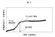
- 1 is an example of a graph showing the relationship between storage modulus and time in a two-liquid mixture addition reaction type silicone resin.
- FIG. 1A is an exploded perspective schematic diagram showing an example of an in-vehicle electronic control unit (in-vehicle ECU) according to the present invention
- FIG. 1B is an exploded perspective schematic diagram showing the exploded perspective view shown in FIG. 1A from the opposite top and bottom sides
- FIG. 1C is a partial cross-sectional schematic diagram of the in-vehicle ECU shown in FIG. 1B.
- an in-vehicle ECU is a type of computer that electronically controls various uses/purposes in driving an automobile or the like (e.g., engine, transmission, steering, airbags, etc.), and has electronic circuits inside.
- an in-vehicle ECU 100 is an example in which the cover 40, of the cover 40, base 50, and fasteners 60 that make up the housing, also serves as a heat dissipation member, and electronic components 10 and connectors 20 are mounted (electrically connected) on a circuit board 30 to form an electronic circuit, which is then housed within the housing (cover 40, base 50) with heat dissipation material 15 interposed between the electronic components 10 and cover 40.
- the electronic component 10 is not particularly limited as long as it is for in-vehicle use, and may be, for example, a semiconductor element such as a CPU (Central Processing Unit), GPU (Graphics Processing Unit), SoC (System on a Chip), or DDR SDRAM (Double-Data-Rate Synchronous Dynamic Random Access Memory).
- a semiconductor element such as a CPU (Central Processing Unit), GPU (Graphics Processing Unit), SoC (System on a Chip), or DDR SDRAM (Double-Data-Rate Synchronous Dynamic Random Access Memory).
- the electronic component 10 is depicted as a BGA (Ball Grid Array) package in which an IC chip 11 is connected on an interposer 12 and connected to a circuit board 30 via bumps 13.
- the electronic component 10 is not limited to a BGA package, and may be a lead frame type package.
- the connector 20 is a part that electrically connects the electronic component 10 mounted on the circuit board 30 to an external device.
- the connector 20 There are no particular limitations on the connector 20, and a conventional connector for use in a vehicle can be used as appropriate.
- the circuit board 30 is a board in which metal wiring is formed on an electrically insulating base material, and like the electronic components 10 and connectors 20, conventional in-vehicle circuit boards can be used as appropriate.
- fixing holes are provided in the outer periphery area, and the circuit board is structured to be fixed to the cover 40 by fasteners 60 (e.g., fixing screws).
- the cover 40 and base 50 are combined with fasteners 60 to form a waterproof, dustproof, sealed housing.
- the cover 40 also functions as a heat dissipation member, as previously described.
- the heat dissipation material (TIM) 15 is disposed so as to be sandwiched and in contact between the cover 40 and the electronic component 10, enabling the heat of the electronic component 10 to be efficiently transferred to the cover 40. Details of the TIM 15 will be described later.
- the heat dissipation pedestal 45 formed on the cover 40 is not a required component of the present invention, but is preferably formed from the standpoint of heat dissipation efficiency and assembly efficiency. Also, while Figures 1A and 1B show an example in which two heat dissipation pedestals 45 are formed to correspond to two electronic components 10, a configuration in which one heat dissipation pedestal 45 corresponds to two electronic components 10 may also be used.
- cover 40 and base 50 there are no particular limitations on the materials used for the cover 40 and base 50, so long as they are heat-resistant, waterproof, dust-proof, and thermally conductive enough for in-vehicle use, metal materials (e.g., aluminum alloys, magnesium alloys, steel materials) and highly thermally conductive resin materials (e.g., polybutylene terephthalate resin (PBT), polyphenylene sulfide resin (PPS), and polyamide resin (PA6) containing thermally conductive filler) can be used as appropriate.
- the heat dissipation member is not limited to the cover 40, and the base 50 may also function as a heat dissipation member, or both the cover 40 and the base 50 may also function as heat dissipation members.
- TIM 15 is also required to function as an adhesive/pressure-sensitive adhesive.
- the material Before curing, it is preferable for the material to have fluidity from the viewpoint of workability, and for example, viscosity: 100 Pa ⁇ s or more and 600 Pa ⁇ s or less is preferable.
- the material after curing, it is preferable for the material not to shift or flow out due to vibrations and stresses caused when the vehicle is running, and for example, a storage modulus G' of more than 0.1 MPa and/or a tensile shear adhesive strength of 0.015 MPa or more is preferable.
- a material with a silicone resin as the matrix for TIM 15, and in particular a two-liquid mixture addition reaction type room temperature curing silicone resin is preferable.
- Silicone resin is a synthetic polymer material with a main skeleton made of siloxane bonds (Si-O-Si bonds). Silicone resin has excellent heat resistance (over 200°C) and chemical stability, and also has elastic properties, which gives it the advantage of being able to absorb and reduce vibrations and shocks.
- the time when this addition reaction is completed is defined as the curing time. This curing time can be calculated from the change in the storage modulus G' of the resin over time.
- Figure 2 is an example of a graph showing the relationship between storage modulus and time in a two-part mixed addition reaction type silicone resin.
- a two-part mixed addition reaction type silicone resin is mixed with a base agent and a curing agent, as shown in Figure 2, a gelation start region (region where curing begins and progresses) appears where the storage modulus increases rapidly, and then a gelation end region (region where curing ends) where the storage modulus is almost saturated is reached.
- a basic skeleton is formed in the gelation end region, and the curing time is defined as the time at the intersection of the tangent of the gelation start region and the tangent of the gelation end region.
- the present invention also adopts this definition.
- the inventors have conducted extensive research into the relationship between these chemical structures and curing time, and have found that the curing time at 15°C can be controlled to within 40 hours by controlling the molar concentrations of these chemical structures to have a predetermined relationship.
- the molar concentrations of each chemical structure can be measured by quantitative analysis using a nuclear magnetic resonance (NMR) device.
- NMR nuclear magnetic resonance
- the molar concentration of the main chain structure "-Si- CH2CH2 - Si-” in the main agent before mixing is 99.09 mol%
- the molar concentration of the -Si-H group in the curing agent is 0.38 mol%, it can obtain a silicone resin with a curing time of 24 hours at 15°C.
- the TIM preferably has a thermal conductivity of 1.5 W/m ⁇ K or more, and more preferably has a thermal conductivity of 2 W/m ⁇ K or more.
- the TIM is preferably made by dispersing and mixing a thermally conductive filler in a silicone resin matrix.
- the thermally conductive filler there are no particular limitations on the thermally conductive filler, so long as it is an electrically insulating material with good thermal conductivity (e.g., 2 W/m ⁇ K or more); for example, aluminum oxide, zinc oxide, magnesium oxide, silicon oxide, aluminum nitride, and boron nitride can be suitably used.
- the storage modulus G' of the cured silicone resin is high. However, if the storage modulus G' is too high, the adhesiveness will decrease and the vibration and stress absorption and relaxation will decrease. If the storage modulus G' is too low, sufficient holding power will not be ensured.
- the storage modulus G' of the cured silicone resin is preferably greater than 0.1 MPa and not greater than 20 MPa, more preferably 0.15 MPa or more and 10 MPa or less, and even more preferably 0.2 MPa or more and 5 MPa or less.
- the adhesive strength of the TIM after curing is preferably 0.015 MPa or more in tensile shear adhesive strength, more preferably 0.020 MPa or more in tensile shear adhesive strength, and even more preferably 0.025 MPa or more in tensile shear adhesive strength.
- Example 2 Measurement of the curing time of room temperature curing silicone resin
- the two-liquid mixed addition reaction type room temperature curable silicone resin (Comparative Example 1 and Examples 1 to 4) prepared in Experiment 1 was used to measure the curing time at 15°C.
- a rheometer Anton Paar Japan, Model: MCR 502
- the change in storage modulus over time was measured under the specified measurement conditions (sample thickness: 3 mm, jig diameter: 25 mm, temperature: 15°C, vibration frequency: 1 Hz, strain: 0.01%), and the curing time was calculated based on the same definition as in Figure 2.
- the storage modulus G' at the curing time was also calculated. The results are shown in Table 1 below.
- Table 1 also show that as the storage modulus of the cured silicone resin increases, the tensile shear bond strength increases. By controlling the storage modulus of the cured silicone resin to greater than 0.1 MPa, the tensile shear bond strength can be made greater than 0.015 MPa.
- the present invention is not limited to the specific configurations described.
- the heat dissipation material used in the present invention is not limited to use in vehicle ECUs, but can also be applied to heat dissipation materials used in inverters, converters, and the like that are not mounted on vehicles.
- 100...In-vehicle electronic control device 10...Electronic component, 11...Chip, 12...Interposer, 13...Bump, 15...Heat dissipation material, 20...Connector, 30...Circuit board, 40...Cover, 45...Heat dissipation base, 50...Base, 60...Fastener.
Landscapes
- Chemical & Material Sciences (AREA)
- Health & Medical Sciences (AREA)
- Chemical Kinetics & Catalysis (AREA)
- Medicinal Chemistry (AREA)
- Polymers & Plastics (AREA)
- Organic Chemistry (AREA)
- Compositions Of Macromolecular Compounds (AREA)
- Cooling Or The Like Of Semiconductors Or Solid State Devices (AREA)
- Structures Or Materials For Encapsulating Or Coating Semiconductor Devices Or Solid State Devices (AREA)
Abstract
Description
前記防水シール材は、熱硬化性の材料が使用され、前記熱伝導材は、加熱されることによって粘度が増加する特性を有する材料が使用され、前記回路基板と前記熱伝導材が筐体内に収容され、かつ、前記各構成部材の接合部位に硬化前の前記防水シール材が配置された状態で前記筐体を加熱する加熱工程を有し、前記加熱工程によって、前記防水シール材の硬化と熱伝導材の粘度の増加が行われることを特徴とする電子制御装置の製造方法、が教示されている。
前記所定の放熱材料はシリコーン樹脂をマトリックスとする材料であり、
前記シリコーン樹脂の中のビニル基構造のモル濃度[-Si-CH=CH2]と主鎖構造のモル濃度[-Si-CH2CH2-Si-]とを核磁気共鳴装置(NMR)を用いて定量分析した場合に、「[-Si-CH=CH2]/[-Si-CH2CH2-Si-]≦0.85」の関係を満たすことを特徴とする。
(i)前記シリコーン樹脂の中の前記ビニル基構造[-Si-CH=CH2]のモル濃度と主骨格構造のモル濃度[-O-Si-(CH3)2-]とを核磁気共鳴装置を用いて定量分析した場合に、「[-Si-CH=CH2]/[-O-Si-(CH3)2-]≦0.95」の関係を満たす。
(ii)前記シリコーン樹脂は、前記ビニル基構造のモル濃度[-Si-CH=CH2]と前記主鎖構造のモル濃度[-Si-CH2CH2-Si-]とが「[-Si-CH=CH2]/[-Si-CH2CH2-Si-]≦0.60」の関係を満たす。
(iii)前記シリコーン樹脂は、前記ビニル基構造のモル濃度[-Si-CH=CH2]と前記主骨格構造のモル濃度[-O-Si-(CH3)2-]とが「[-Si-CH=CH2]/[-O-Si-(CH3)2-]≦0.65」の関係を満たす。
(iv)前記シリコーン樹脂は、前記ビニル基構造のモル濃度[-Si-CH=CH2]と前記主鎖構造のモル濃度[-Si-CH2CH2-Si-]とが「[-Si-CH=CH2]/[-Si-CH2CH2-Si-]≦0.40」の関係を満たす。
(v)前記シリコーン樹脂は、前記ビニル基構造のモル濃度[-Si-CH=CH2]と前記主骨格構造のモル濃度[-O-Si-(CH3)2-]とが「[-Si-CH=CH2]/[-O-Si-(CH3)2-]≦0.45」の関係を満たす。
(vi)前記シリコーン樹脂は、貯蔵弾性率が0.1 MPa超である。
(vii)前記シリコーン樹脂は、貯蔵弾性率が0.15 MPa以上である。
(viii)前記シリコーン樹脂は、貯蔵弾性率が0.2 MPa以上である。
(ix)前記シリコーン樹脂は、引張剪断接着強さが0.015 MPa以上ある。
(x)前記シリコーン樹脂は、引張剪断接着強さが0.020 MPa以上ある。
(xi)前記シリコーン樹脂は、引張剪断接着強さが0.025 MPa以上ある。
(xii)前記シリコーン樹脂は、二液混合付加反応型の常温硬化性シリコーン樹脂である。
前述したように、本発明者等は、15℃における常温硬化性TIMの硬化時間を調査した。常温硬化性TIMとしては、二液混合付加反応型の常温硬化性シリコーン樹脂を選定し、該シリコーン樹脂を構成する化学的構造に着目して、該化学的構造と硬化時間との関係を鋭意調査・研究した。
図1Aは、本発明に係る車載電子制御装置(車載ECU)の一例を示す分解斜視概略図であり、図1Bは、図1Aに示した分解斜視図を上下反対側から見た分解斜視概略図であり、図1Cは、図1Bに示した車載ECUの部分断面概略図である。
(比較例1および実施例1~4の用意)
市販の二液混合付加反応型の常温硬化性シリコーン樹脂(比較例1)を用意した。一方、混合前の主剤中の主鎖構造「-Si-CH2CH2-Si-」およびビニル基「-Si-CH=CH2」のモル濃度の制御や、硬化剤の混合比の制御を行って、硬化後においてシリコーン樹脂中に残存するビニル基構造のモル濃度が異なる二液混合付加反応型の常温硬化性シリコーン樹脂(実施例1~4)を用意した。
(常温硬化性シリコーン樹脂の硬化時間の測定)
実験1で用意した二液混合付加反応型の常温硬化性シリコーン樹脂(比較例1および実施例1~4)を用いて、15℃における硬化時間の測定を行った。レオメータ(株式会社アントンパール・ジャパン、型式:MCR 502)を用いて、所定の測定条件(試料厚さ:3mm、ジグ径:25mm、温度:15℃、振動周波数:1Hz、ひずみ:0.01%)で貯蔵弾性率の時間変化を測定し、図2と同じ定義に基づいて硬化時間を求めた。また、併せて硬化時間の時の貯蔵弾性率G’も求めた。結果を後述する表1に記す。
(硬化したシリコーン樹脂中の化学的構造のモル濃度の測定)
硬化後の各シリコーン樹脂(比較例1および実施例1~4)に対して、樹脂中に残存している主骨格構造のモル濃度[-O-Si-(CH3)2-]、主鎖構造のモル濃度[-Si-CH2CH2-Si-]、およびビニル基構造のモル濃度[-Si-CH=CH2]の定量分析を行った。NMR装置(日本電子株式会社、型式:ECA-500FT-NMR)を用いて、所定の測定条件(測定核種:1H、磁場強度:11.7 T(1H核にて500 MHz)、観測周波数範囲:-2.5 ppm~12.5 ppm(45°パルス)、データ点数:16384 point、測定モード:13Cデカップリング、繰り返し時間:30 s、積算回数:256回、測定溶媒:重水素化クロロホルム、測定温度:室温)で、各化学的構造のモル濃度を測定し、各化学的構造のモル濃度の比を算出した。結果を表1に併記する。
(硬化したシリコーン樹脂の引張剪断接着強さの測定)
実験1で用意した二液混合付加反応型の常温硬化性シリコーン樹脂(比較例1および実施例1~4)を用いて、JIS K6850に準拠して引張剪断接着強さを測定した。精密万能試験機(株式会社島津製作所、型式:AGS-H 500N)を用いて、引張速度5 mm/minの条件で最大荷重を測定し、剪断面積で除して引張剪断接着強さを求めた。結果を表1に併記する。

Claims (13)
- 電子部品と放熱部材との間に所定の放熱材料を介在させた車載電子制御装置であって、
前記所定の放熱材料はシリコーン樹脂をマトリックスとする材料であり、
前記シリコーン樹脂の中のビニル基構造のモル濃度[-Si-CH=CH2]と主鎖構造のモル濃度[-Si-CH2CH2-Si-]とを核磁気共鳴装置を用いて定量分析した場合に、「[-Si-CH=CH2]/[-Si-CH2CH2-Si-]≦0.85」の関係を満たすことを特徴とする車載電子制御装置。 - 請求項1に記載の車載電子制御装置において、
前記シリコーン樹脂の中の前記ビニル基構造[-Si-CH=CH2]のモル濃度と主骨格構造のモル濃度[-O-Si-(CH3)2-]とを核磁気共鳴装置を用いて定量分析した場合に、「[-Si-CH=CH2]/[-O-Si-(CH3)2-]≦0.95」の関係を満たすことを特徴とする車載電子制御装置。 - 請求項1又は請求項2に記載の車載電子制御装置において、
前記シリコーン樹脂は、前記ビニル基構造のモル濃度[-Si-CH=CH2]と前記主鎖構造のモル濃度[-Si-CH2CH2-Si-]とが「[-Si-CH=CH2]/[-Si-CH2CH2-Si-]≦0.60」の関係を満たすことを特徴とする車載電子制御装置。 - 請求項2に記載の車載電子制御装置において、
前記シリコーン樹脂は、前記ビニル基構造のモル濃度[-Si-CH=CH2]と前記主骨格構造のモル濃度[-O-Si-(CH3)2-]とが「[-Si-CH=CH2]/[-O-Si-(CH3)2-]≦0.65」の関係を満たすことを特徴とする車載電子制御装置。 - 請求項3又は請求項4に記載の車載電子制御装置において、
前記シリコーン樹脂は、前記ビニル基構造のモル濃度[-Si-CH=CH2]と前記主鎖構造のモル濃度[-Si-CH2CH2-Si-]とが「[-Si-CH=CH2]/[-Si-CH2CH2-Si-]≦0.40」の関係を満たすことを特徴とする車載電子制御装置。 - 請求項4に記載の車載電子制御装置において、
前記シリコーン樹脂は、前記ビニル基構造のモル濃度[-Si-CH=CH2]と前記主骨格構造のモル濃度[-O-Si-(CH3)2-]とが「[-Si-CH=CH2]/[-O-Si-(CH3)2-]≦0.45」の関係を満たすことを特徴とする車載電子制御装置。 - 請求項1乃至請求項6のいずれか一項に記載の車載電子制御装置において、
前記シリコーン樹脂は、貯蔵弾性率が0.1 MPa超であることを特徴とする車載電子制御装置。 - 請求項1乃至請求項6のいずれか一項に記載の車載電子制御装置において、
前記シリコーン樹脂は、貯蔵弾性率が0.15 MPa以上であることを特徴とする車載電子制御装置。 - 請求項1乃至請求項6のいずれか一項に記載の車載電子制御装置において、
前記シリコーン樹脂は、貯蔵弾性率が0.2 MPa以上であることを特徴とする車載電子制御装置。 - 請求項1乃至請求項6のいずれか一項に記載の車載電子制御装置において、
前記シリコーン樹脂は、引張剪断接着強さが0.015 MPa以上あることを特徴とする車載電子制御装置。 - 請求項1乃至請求項6のいずれか一項に記載の車載電子制御装置において、
前記シリコーン樹脂は、引張剪断接着強さが0.020 MPa以上あることを特徴とする車載電子制御装置。 - 請求項1乃至請求項6のいずれか一項に記載の車載電子制御装置において、
前記シリコーン樹脂は、引張剪断接着強さが0.025 MPa以上あることを特徴とする車載電子制御装置。 - 請求項1乃至請求項6のいずれか一項に記載の車載電子制御装置において、
前記シリコーン樹脂は、二液混合付加反応型の常温硬化性シリコーン樹脂であることを特徴とする車載電子制御装置。
Priority Applications (2)
| Application Number | Priority Date | Filing Date | Title |
|---|---|---|---|
| CN202380082104.9A CN120380594A (zh) | 2022-12-21 | 2023-08-28 | 车载电子控制装置 |
| DE112023004434.1T DE112023004434T5 (de) | 2022-12-21 | 2023-08-28 | Bordeigene elektronische steuervorrichtung |
Applications Claiming Priority (2)
| Application Number | Priority Date | Filing Date | Title |
|---|---|---|---|
| JP2022203996A JP7818498B2 (ja) | 2022-12-21 | 2022-12-21 | 車載電子制御装置 |
| JP2022-203996 | 2022-12-21 |
Publications (1)
| Publication Number | Publication Date |
|---|---|
| WO2024134993A1 true WO2024134993A1 (ja) | 2024-06-27 |
Family
ID=91588025
Family Applications (1)
| Application Number | Title | Priority Date | Filing Date |
|---|---|---|---|
| PCT/JP2023/030998 Ceased WO2024134993A1 (ja) | 2022-12-21 | 2023-08-28 | 車載電子制御装置 |
Country Status (4)
| Country | Link |
|---|---|
| JP (1) | JP7818498B2 (ja) |
| CN (1) | CN120380594A (ja) |
| DE (1) | DE112023004434T5 (ja) |
| WO (1) | WO2024134993A1 (ja) |
Families Citing this family (1)
| Publication number | Priority date | Publication date | Assignee | Title |
|---|---|---|---|---|
| JP2026014417A (ja) * | 2024-07-19 | 2026-01-29 | Astemo株式会社 | 熱界面材料および該熱界面材料を用いた車載電子制御装置 |
Citations (6)
| Publication number | Priority date | Publication date | Assignee | Title |
|---|---|---|---|---|
| JP2001026721A (ja) * | 1999-07-14 | 2001-01-30 | Chisso Corp | シリコーン変性ビニル系樹脂、その製造方法およびそれを含有するコーティング剤 |
| JP2016216523A (ja) * | 2015-05-14 | 2016-12-22 | デンカ株式会社 | 熱伝導性グリース用組成物、熱伝導性グリースおよび放熱部材 |
| WO2017060999A1 (ja) * | 2015-10-08 | 2017-04-13 | 三菱電機株式会社 | 電気機器のケース及びその製造方法 |
| JP2017088853A (ja) * | 2015-11-05 | 2017-05-25 | ダウ コーニング コーポレーションDow Corning Corporation | 分枝状ポリオルガノシロキサン並びに関連する硬化性組成物、方法、使用及びデバイス |
| JP2019131734A (ja) * | 2018-02-01 | 2019-08-08 | 信越化学工業株式会社 | 2液付加反応硬化型放熱シリコーン組成物及びその製造方法 |
| WO2021053979A1 (ja) * | 2019-09-17 | 2021-03-25 | 信越化学工業株式会社 | シリコーン組成物およびその硬化物 |
-
2022
- 2022-12-21 JP JP2022203996A patent/JP7818498B2/ja active Active
-
2023
- 2023-08-28 WO PCT/JP2023/030998 patent/WO2024134993A1/ja not_active Ceased
- 2023-08-28 CN CN202380082104.9A patent/CN120380594A/zh active Pending
- 2023-08-28 DE DE112023004434.1T patent/DE112023004434T5/de active Pending
Patent Citations (6)
| Publication number | Priority date | Publication date | Assignee | Title |
|---|---|---|---|---|
| JP2001026721A (ja) * | 1999-07-14 | 2001-01-30 | Chisso Corp | シリコーン変性ビニル系樹脂、その製造方法およびそれを含有するコーティング剤 |
| JP2016216523A (ja) * | 2015-05-14 | 2016-12-22 | デンカ株式会社 | 熱伝導性グリース用組成物、熱伝導性グリースおよび放熱部材 |
| WO2017060999A1 (ja) * | 2015-10-08 | 2017-04-13 | 三菱電機株式会社 | 電気機器のケース及びその製造方法 |
| JP2017088853A (ja) * | 2015-11-05 | 2017-05-25 | ダウ コーニング コーポレーションDow Corning Corporation | 分枝状ポリオルガノシロキサン並びに関連する硬化性組成物、方法、使用及びデバイス |
| JP2019131734A (ja) * | 2018-02-01 | 2019-08-08 | 信越化学工業株式会社 | 2液付加反応硬化型放熱シリコーン組成物及びその製造方法 |
| WO2021053979A1 (ja) * | 2019-09-17 | 2021-03-25 | 信越化学工業株式会社 | シリコーン組成物およびその硬化物 |
Also Published As
| Publication number | Publication date |
|---|---|
| JP2024088942A (ja) | 2024-07-03 |
| DE112023004434T5 (de) | 2025-08-07 |
| CN120380594A (zh) | 2025-07-25 |
| JP7818498B2 (ja) | 2026-02-20 |
Similar Documents
| Publication | Publication Date | Title |
|---|---|---|
| CN110828405B (zh) | 功率半导体模块以及车辆 | |
| CN1722431A (zh) | 发动机控制电路装置 | |
| JP7818498B2 (ja) | 車載電子制御装置 | |
| US9560744B2 (en) | Component and method for producing a component | |
| JP6143980B1 (ja) | 電力変換装置 | |
| CN104871311A (zh) | 电子控制装置及电子控制装置的基板连接方法 | |
| CN102754205A (zh) | 电源模块及其制造方法 | |
| JP2020053438A (ja) | 半導体モジュールおよび車両 | |
| US20150008804A1 (en) | Motor control unit | |
| JP2013021855A (ja) | 電力変換装置 | |
| US20100102431A1 (en) | Power module and inverter for vehicles | |
| WO2026018538A1 (ja) | 熱界面材料および該熱界面材料を用いた車載電子制御装置 | |
| JP4269213B2 (ja) | 電子回路付駆動装置 | |
| WO2017175274A1 (ja) | 封止構造体及びその製造方法 | |
| DE102020105510A1 (de) | Halbleitermodul und verfahren für seine herstellung | |
| JP2016018829A (ja) | 基板組立体 | |
| JP7469969B2 (ja) | パワーモジュール | |
| US20220108959A1 (en) | Semiconductor module | |
| US20240395658A1 (en) | Semiconductor device and manufacturing method of semiconductor device | |
| JP2008270257A (ja) | 半導体装置およびその製造方法 | |
| JP7565371B2 (ja) | 電子制御装置 | |
| JP2595292B2 (ja) | 電気・電子部品封止用樹脂組成物 | |
| JP2013012728A (ja) | ボンディングワイヤ、接続部構造、並びに半導体装置およびその製造方法 | |
| JP2023028314A (ja) | 電子制御装置 | |
| JP2020155765A (ja) | 半導体モジュールおよび製造方法 |
Legal Events
| Date | Code | Title | Description |
|---|---|---|---|
| 121 | Ep: the epo has been informed by wipo that ep was designated in this application |
Ref document number: 23906370 Country of ref document: EP Kind code of ref document: A1 |
|
| WWE | Wipo information: entry into national phase |
Ref document number: 202380082104.9 Country of ref document: CN |
|
| WWE | Wipo information: entry into national phase |
Ref document number: 112023004434 Country of ref document: DE |
|
| WWP | Wipo information: published in national office |
Ref document number: 202380082104.9 Country of ref document: CN |
|
| WWP | Wipo information: published in national office |
Ref document number: 112023004434 Country of ref document: DE |
|
| 122 | Ep: pct application non-entry in european phase |
Ref document number: 23906370 Country of ref document: EP Kind code of ref document: A1 |