WO2024134876A1 - スライドファスナー用ロック機構 - Google Patents
スライドファスナー用ロック機構 Download PDFInfo
- Publication number
- WO2024134876A1 WO2024134876A1 PCT/JP2022/047624 JP2022047624W WO2024134876A1 WO 2024134876 A1 WO2024134876 A1 WO 2024134876A1 JP 2022047624 W JP2022047624 W JP 2022047624W WO 2024134876 A1 WO2024134876 A1 WO 2024134876A1
- Authority
- WO
- WIPO (PCT)
- Prior art keywords
- locking
- pair
- sliders
- slider
- slide fastener
- Prior art date
- Legal status (The legal status is an assumption and is not a legal conclusion. Google has not performed a legal analysis and makes no representation as to the accuracy of the status listed.)
- Ceased
Links
Images




Classifications
-
- A—HUMAN NECESSITIES
- A44—HABERDASHERY; JEWELLERY
- A44B—BUTTONS, PINS, BUCKLES, SLIDE FASTENERS, OR THE LIKE
- A44B19/00—Slide fasteners
- A44B19/24—Details
- A44B19/26—Sliders
-
- A—HUMAN NECESSITIES
- A44—HABERDASHERY; JEWELLERY
- A44B—BUTTONS, PINS, BUCKLES, SLIDE FASTENERS, OR THE LIKE
- A44B19/00—Slide fasteners
- A44B19/24—Details
- A44B19/26—Sliders
- A44B19/30—Sliders with means for locking in position
- A44B19/303—Self-locking sliders, e.g. slider body provided with locking projection or groove, friction means
Definitions
- the present invention relates to a locking mechanism for a slide fastener that detachably connects a pair of sliders.
- the zipper When opening and closing a bag or other item with a slide fastener, the zipper may open unintentionally, causing items to fall out of the opening.
- the bag with a slide fastener at the opening is a backpack, the opening is located behind the user and can be opened and closed easily, so there is a risk that items may be stolen from the opening in such a short time that the owner does not notice.
- a pair of sliders are slidably arranged on a pair of fastener stringers, and are provided with an engaging portion and an engaged portion that detachably connect the pair of sliders to each other.
- the slide fastener connector described in Patent Document 1 provides an engagement portion and an engaged portion that detachably connect a pair of sliders with their openings closed, improving security.
- the engagement portion which is a convex portion provided on one slider
- the engaged portion which is a concave portion provided on the other slider
- a certain level of strong force is required to lock and unlock the pair of sliders, which poses problems in terms of operability and durability. Therefore, there is a demand for a slide fastener locking mechanism with a simple configuration that makes it easy to lock and unlock the pair of sliders.
- the present invention was made in consideration of the above-mentioned problems, and aims to provide a locking mechanism for a slide fastener that has a simple configuration and allows smooth and easy locking and unlocking of a pair of sliders.
- a locking mechanism for a slide fastener comprising a pair of sliders (10, 10) slidably disposed on a pair of fastener stringers (2, 2) for engaging or separating the pair of left and right fastener stringers (2, 2), and a locking section (20, 40) for detachably connecting the pair of sliders (10, 10) to each other,
- the locking portions (20, 40) disposed at the shoulder side ends of the pair of sliders (10, 10) are
- the longitudinal direction of the fastener stringer (2) is defined as the front-rear direction and the extending direction of the connecting column (14) connecting the upper wing (11) and the lower wing (12) of the slider (10) is defined as the up-down direction
- a base portion (26, 46) provided on one of the upper blade (11) or the lower blade (12) of the slider (10) and extending from a shoulder side of the slider (10) in a front-rear direction in a direction in which the pair of sliders (10
- Locking mechanism for slide fasteners [2] In the pair of sliders (10, 10), when the upper blade (11) of one slider (10) has an extending base portion (26), the upper blade (11) of the other slider (10) does not have an extending base portion (26). A locking mechanism for a slide fastener according to [1]. [3] At least one of the hook portions (27, 47) of the pair of sliders (10, 10) has an inclined surface (27A, 27B) inclined toward the rear mouth direction of the slider (10) toward its tip direction, A locking mechanism for a slide fastener according to [1].
- At least a part of the inclined surface (27A, 27B) of at least one of the hook portions (27, 47) of the pair of sliders (10, 10) is formed at a position beyond the midpoint between the outer surface of the upper blade (11) and the outer surface of the lower blade (12).
- the left-right width of the hook portion (27) is equal to or less than the left-right width of the slider (10),
- the hook portion (27) is disposed on the center side in the left-right width direction of the slider (10).
- the left and right width of the hook portion (27) is 0.3 times or more the left and right width of the connecting column (14), A locking mechanism for a slide fastener according to [5].
- the locking portion (20, 40) is a locking member that is detachable from the slider (10), and the locking member (20, 40) has a first surface portion (21, 41) arranged on one of the upper blade (11) or the lower blade (12), a second surface portion (22, 42) arranged on the other of the upper blade (11) or the lower blade (12), and a vertical connection portion (23, 43) that connects the first surface portion (21, 41) and the second surface portion (22, 42) and is arranged along the shoulder side of the connecting column (14),
- the second surface portion (22, 42) has the base portion (26, 46) and the hook portion (27, 47), At least one of the first surface portion (21, 41) and the second surface portion (22, 42) is formed with a locking portion (24, 25) for detachably locking the locking member (20
- a locking mechanism for a slide fastener according to [1].
- the engaging portions (24, 25) are provided on the first surface portion (21) and the second surface portion (22), The pair of locking members (20, 20, 40, 40) are formed to have the same shape.
- the locking portion (24, 25) has a pair of locking pieces (24A, 24B, 25A, 25B) that sandwich the pull-handle mounting post (13), one of the locking pieces (24B, 25B) is formed in a straight line along the side surface of the pull-handle mounting post 13, and the other locking piece (24A, 25B) is formed in an L-shape so as to surround the pull-handle mounting post 13.
- the connection portion (23) is formed with a restricting portion (29) protruding in the front-rear direction so as to abut against the connecting column (14) in the left-right direction.
- the L-shaped locking pieces (24A, 25A) are disposed on one of the left and right sides of the pull-tab mounting post (13),
- the restricting portion (29) is disposed on the other of the left and right sides of the connecting pillar (14).
- a pair of the restricting portions (29) are provided so as to sandwich the side surfaces of the connecting pole (14) in the left-right direction.
- the locking mechanism for a slide fastener according to [10]. [13] The locking portions (20, 40) are integrally molded with the pair of sliders (10, 10), respectively. A locking mechanism for a slide fastener according to any one of [1] to [6].
- the base portion (46) has a lower base portion (46A) and an upper base portion (46B) arranged side by side and offset in the vertical direction
- the hook portion (47) has a first hook portion (47A) protruding upward from the lower base portion (46A) and a second hook portion (47B) protruding downward from the upper base portion (46B),
- a lock portion (40) on each of the pair of sliders (10, 10) a first hook portion (47A) and a second hook portion (47B) that are arranged opposite each other between the shoulders of the pair of sliders (10, 10) are engaged with and disengaged from each other.
- a locking mechanism for a slide fastener according to [1].
- the present invention allows the pair of sliders to be locked and unlocked smoothly and easily with a simple configuration.
- 1 is a perspective view showing a slide fastener equipped with a locking mechanism for a slide fastener according to an embodiment of the present invention
- 1A and 1B are a side view and a plan view, respectively, showing a pair of sliders equipped with a locking mechanism.
- 1A, 1B, and 1C are a side view, a plan view, and a front view, respectively, showing a slider to which a locking member is attached.
- FIG. 4 is a perspective view showing a slider to which a locking member is attached.
- 4A and 4B are a plan view and a bottom view, respectively, showing a locking member.
- 1A is a perspective view showing a locking member
- FIG. 11 is a perspective view showing a locking member according to a first modified embodiment.
- 6A is a perspective view showing a locking member of Modified Example 2
- FIG. 6B is a cross-sectional view taken along line AA of a slider to which the locking member of Modified Example 2 is attached, similar to FIG. 6B.
- FIG. 11 is a perspective view showing a locking mechanism for a slide fastener according to a third embodiment of the present invention.
- 13A and 13B are a side view and a plan view, respectively, showing a locking mechanism for a slide fastener according to a third modified embodiment of the present invention.
- a slide fastener incorporating a locking mechanism for a slide fastener (hereinafter simply referred to as a "locking mechanism") according to one embodiment of the present invention will be described with reference to Figures 1 to 6 (B). Note that the present invention is not limited to the embodiment described below, and various modifications are possible as long as they have substantially the same configuration as the present invention and provide similar operational effects.
- FIG. 1 is a perspective view showing a slide fastener equipped with a locking mechanism for a slide fastener according to this embodiment
- FIGS. 2(A) and (B) are a side view and a plan view, respectively, showing a pair of sliders equipped with a locking mechanism.
- the slide fastener 1 comprises a pair of fastener stringers 2, 2 and a pair of sliders 10, 10 arranged to slide freely along the fastener stringers 2, 2.
- the slide fastener 1 is provided with a locking mechanism by removably attaching locking members 20 to each of the pair of sliders 10, 10.
- a pair of fastener stringers 2, 2 has a row of fastener elements 2B, 2B attached to the opposing tape edges of a pair of fastener tapes 2A, 2A. Note that in Figure 1, the fastener elements 2B, 2B are shown in a simplified form.
- the slider 10 has an upper wing 11, a lower wing 12, a connecting post 14 connecting the upper wing 11 and the lower wing 12, and a pull tab mounting post 13 provided on the upper wing 11 to attach a pull tab 16 to the upper wing 11.
- a guide path through which the fastener elements 2B, 2B pass is formed between the upper wing 11 and the lower wing 12.
- the connecting post 14 is disposed on the shoulder side of the slider 10 of the guide path (the center side in the left-right direction in Fig. 2 (A) and (B)).
- a flange portion 15 is provided on the rear side of the guide path of the slider 10 (the outer side in the left-right direction in Fig.
- the longitudinal direction of the fastener stringers 2, 2, i.e., the direction in which the slider 10 moves to open and close the pair of fastener stringers 2, 2, is referred to as the front-rear direction.
- the front of the locking member 20 (slider 10) refers to the direction in which it approaches the other locking member 20 in the front-rear direction.
- the front of the locking member 20 (slider 10) can also be referred to as the shoulder side of the slider 10.
- the rear of the locking member 20 (slider 10) refers to the direction in which it moves away from the other locking member 20 in the front-rear direction.
- the rear of the locking member 20 can also be referred to as the rear side of the slider 10.
- the direction in which the pair of fastener stringers 2, 2 are arranged is referred to as the left-right direction or width direction.
- the direction perpendicular to the front-rear direction and the left-right direction, i.e., the extension direction of the connecting pillar 14, is referred to as the up-down direction.
- Figures 3(A) to 3(C) and Figure 4 are respectively a side view, a plan view, a front view and a perspective view of a slider to which a locking member is attached
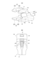
- Figures 5(A) and 5(B) are respectively a plan view and a bottom view of the locking member
- Figure 6(A) is a perspective view of the locking member
- Figure 6(B) is an A-A cross-sectional view of the slider to which a locking member is attached.
- the locking member 20 includes a first surface 21, a second surface 22, and a connecting portion 23.
- the first surface 21 is disposed on one side of the upper surface of the upper blade 11 or the lower surface of the lower blade 12, and the second surface 22 is disposed on the other side of the upper surface of the upper blade 11 or the lower surface of the lower blade 12.
- the connecting portion 23 is provided in front of the shoulder end of the slider 10, and extends in the vertical direction along the connecting post 14 of the slider 10, and connects the first surface 21 and the second surface 22. That is, the locking member 20 has a U-shape so as to sandwich the outer surfaces of the upper blade 11 and the lower blade 12 in the vertical direction from the shoulder side of the slider 10 .
- the first surface 21 and the second surface 22 have steps 21a, 22a formed on their opposing surfaces against which the front end of the upper wing 11 or the lower wing 12 abuts. That is, the shoulder end of the slider 10 abuts against the pair of steps 21a, 22a and the connection portion 23, thereby determining the attachment position of the slider 10 to the locking member 20 (see FIG. 3(A)).
- the step portions 21a and 22a are formed in a straight line in the left-right direction when viewed from the top-down direction, but they may also be curved in an arc shape to match the shape of the shoulder side of the slider 10.
- the first surface 21 and the second surface 22 are each formed with locking portions 24, 25 that extend rearward from the shoulder side of the slider 10 where the connection portion 23 is located, and that allow the locking member 20 to be detachably attached to the handle mounting post 13 when provided along the upper surface of the upper wing plate 11.
- the locking portions 24, 25 have a first locking piece 24A, 25A formed along one of the left and right side surfaces of the pull-handle mounting post 13, and a second locking piece 24B, 25B formed along the other left and right side surface.
- the first locking piece 24A, 25A is bent in an L-shape at the extended end so as to surround the pull-handle mounting post 13
- the second locking piece 24B, 25B is formed in a straight line along the side surface of the pull-handle mounting post 13, and has a notch 24B1, 25B1 at the extended end that is inclined in a direction away from the pull-handle mounting post 13.
- both the first locking piece 24A, 25A and the second locking piece 24B, 25B may be bent in an L-shape at the extended end so as to surround the pull-handle mounting post 13.
- the locking parts 24, 25 are asymmetrically configured with an L-shaped first locking piece 24A, 25A that has a high locking force on the pull-handle mounting post 13, and a straight second locking piece 24B, 25B that allows for smooth attachment and detachment to the pull-handle mounting post 13. This makes it difficult for the locking member 20 attached to the pull-handle mounting post 13 to come off, while also making it easy to attach and detach the locking member 20 to and from the pull-handle mounting post 13.
- the second surface portion 22 has a plate-shaped base portion 26 that extends from the shoulder side of the slider 10 toward the front, which is the direction approaching the other slider 10, and a claw-shaped hook portion 27 that protrudes in the vertical direction from the extended end of the base portion 26.
- the base portion 26 is formed thicker than the upper blade 11 and the lower blade 12.
- the inner surface of the base portion 26 on which the hook portion 27 is formed is formed on the same plane as the upper blade 11 or the lower blade 12 with almost no step between them across the connection portion 23 in a side view.
- the width direction dimension of the base portion 26 has a left-right width that is approximately the same as that of the upper blade 11 or the lower blade 12 in a plan view (see FIG. 3B). In this case, it is preferable that the width dimension of the base portion 26 is equal to or smaller than the maximum width dimension of the slider 10 and equal to or larger than the width dimension of the hook portion 27.
- the hook portion 27 has a width equal to or less than the width of the base portion 26, and is positioned at the center of the base portion 26 in the width direction (see Figs. 5(A) and 6(B)). This ensures space for the fastener elements 2B, 2B to pass through on the left and right outer sides of the hook portion 27, allowing the slider 10 provided with the locking member 20 to smoothly slide along the fastener stringer 2.
- the hook portion 27 is formed to be approximately the same width as the connection portion 23, but it may be made as wide as the base portion 26 to prioritize the strength of the hook portion 27.
- the hook portion 27 may be made narrower than the connecting post 14, which is thinner than the connection portion 23.
- the width of the hook portion 27 is 0.3 times or more the width of the connecting post.
- the width of the hook portion 27 is equal to or smaller than the width of the slider 10 or the width of the base portion 26.
- the width of the hook portion 27 is equal to or smaller than the width of the connecting post.
- the hook portion 27 is inclined toward the rear, which is the direction of the rear opening of the slider 10, toward the tip.
- the hook portion 27 has two inclined surfaces 27A and 27B at different angles on the front surface, which is the surface facing the slider 10 on the other side.
- the inclined surfaces 27A and 27B constituting the hook portion 27 include a first inclined surface 27A on the base end side in the vertical direction and a second inclined surface 27B on the tip end side in the vertical direction, and the second inclined surface 27B is formed so as to have a greater rearward inclination than the first inclined surface 27A.
- the second inclined surface 27B is formed so as to straddle at least the intermediate position O in the vertical direction between the outer surface of the upper blade 11 and the outer surface of the lower blade 12 (see FIG. 2A).
- the first inclined surface 27A may be formed so as to straddle the intermediate position O.
- the hook portions 27 are not limited to the above configuration as long as they are formed such that the inclined surfaces 27B of the hook portions 27 come into contact with each other when the pair of sliders 10, 10 on which the hook portions 27 are provided are closed.
- the hook portions 27 provided on the pair of sliders 10, 10 only the inclined surfaces 27A, 27B of the hook portions 27 on one side may be formed at a position beyond the intermediate position O.
- first surface 21 and the front side of the connection portion 23 are formed with a generally planar cutout surface 28 that is inclined forward toward the base portion 26 of the second surface 22 in a side view.
- the inclination angle of the cutout surface 28 is formed to be approximately the same as the first inclined surface 27A of the hook portion 27.
- a connection space is formed in front of the first surface 21 and the connection portion 23 for connecting the hook portion 27 to the hook portion 27 provided on the slider 10 on the other side.
- connection portion 23 is provided with a restricting portion 29 that protrudes in the front-rear direction so as to abut against one of the left and right side surfaces of the connecting post 14 of the slider 10 (see Figs. 6(A) and 6(B)).
- the restricting portion 29 abuts against the side surface opposite to the left and right side surface on which the L-shaped first locking pieces 24A, 25A are arranged along one of the left and right side surfaces of the pull-tab mounting post 13.
- the second locking piece 24B of the first surface portion 21, the restricting portion 29, and the second locking piece 25B of the second surface portion 22 are arranged in a vertical line.
- the restricting portion 29 can hold down the side of the connecting post 14 on the side of the second locking pieces 24B, 25B, which do not have sufficient locking force on the handle mounting post 13, making the locking member 20 attached to the slider 10 more stable and reducing rattling of the locking member 20.
- a locking mechanism is formed by attaching a first locking member 20A to one slider 10 and a second locking member 20B to the other slider 10 in a point-symmetrical state, that is, upside down and left to right inverted.
- the first locking member 20A and the second locking member 20B have the same shape.
- the first locking member 20A attached to the slider 10 on one side has the second surface 22 arranged along the underside of the lower blade 12, so that the base portion 26 extends along the lower blade 12, and the hook portion 27 protrudes from the base portion 26 toward the upper blade 11 in the vertical direction.
- the second locking member 20B attached to the slider 10 on the other side has the second surface 22 arranged along the upper blade 11, so that the base portion 26 extends along the upper blade 11, and the hook portion 27 protrudes from the base portion 26 toward the lower blade 12 in the vertical direction.
- the locking operation of the locking mechanism can be performed smoothly and easily without using a large force that would elastically deform the first locking member 20A and the second locking member 20B.
- the inclination angles of the inclined surfaces 27A and 27B of the hook portions 27 provided on the pair of sliders 10, 10 are the same. This makes the locking operation smooth.
- the inclination angles of the inclined surfaces 27A and 27B of the hook portions 27 provided on the pair of sliders 10, 10 are formed to be approximately the same in order to make the locking operation smooth. It is also preferable that the inclined surfaces 27A and 27B of the pair of hook portions are in surface contact with each other.
- the above-mentioned unlocking operation will be specifically described.
- the engagement between the hook portions 27 can be easily released by twisting the connected first locking member 20A and second locking member 20B in a direction that rotates about an axis relative to the front-rear direction or by shifting them in the up-down direction. That is, the unlocking operation of the locking mechanism can be performed smoothly and easily without using a large force that would elastically deform the first locking member 20A and the second locking member 20B.
- the locking member 20 were configured to be locked and unlocked by hooks on the left and right, it would be difficult to perform the unlocking operation because it would require force to remove the slider 10 in the width direction when performing the unlocking operation. Also, depending on the sewing conditions of the fastener stringer 2, there may not be enough room to move the slider 10 left and right, making the unlocking operation difficult.
- the unlocking can be easily performed with one hand by pressing downward only the upper surface of the first face portion 21 of the first locking member 20A (hereinafter, the unlocking operation position X), where the hook portion 27 is formed upward from the lower blade 12 side, among the upper surface sides of the connected first locking member 20A and second locking member 20B (see FIG. 2(A)).
- the first surface 21 of the first locking member 20A and the second surface 22 of the second locking member 20B are arranged side by side on the upper surface side of the pair of connected sliders 10, 10. Therefore, the user can easily recognize that the first surface 21 of the locking member 20, which has a shorter length, is the unlocking operation position X for performing the unlocking operation.
- the locking member 20 described above has locking portions 24, 25 on both the first surface 21 and the second surface 22 that lock onto the handle mounting post 13, making it possible to make the pair of locking members 20 completely identical in shape. This makes it possible to keep the manufacturing costs of the pair of locking members 20 that make up the locking mechanism low.
- the above-mentioned locking mechanism is configured by attaching a detachable locking member 20 to each of a pair of sliders 10, but instead of the locking member 20, a locking portion (not shown) equivalent to the locking member 20 may be integrally molded with the slider 10.
- the base portion 26 can be extended along the upper wing 11 or the lower wing 12, so that it can be formed thinner in the vertical (thickness) direction. This makes it possible to make the entire locking mechanism more compact and stronger.
- FIG. 7 is a perspective view showing the locking member of the another embodiment.
- the locking member 20C has a first surface portion 21, a second surface portion 22, and a connection portion 23.
- connection portion 23 is provided with a restricting portion 29 that protrudes in the front-rear direction so as to abut against one of the left and right side surfaces of the connecting post 14 of the slider 10.
- the restricting portion 29 abuts against the side surface in the same direction as the side surface on which the L-shaped first locking pieces 24A, 25A are arranged along one of the left and right side surfaces of the pull-handle mounting post 13.
- the L-shaped first locking piece 24A of the first surface portion 21, the restricting portion 29, and the L-shaped first locking piece 25A of the second surface portion 22 are arranged side by side in the vertical direction.
- the restricting portion 29 does not get in the way when attaching the engaging portions 24, 25 to the handle mounting post 13, so the ease of attaching and detaching the locking member 20C to the slider 10 remains unchanged, and rattling of the locking member 20C attached to the slider 10 can be reduced.
- Figure 8(A) is a perspective view showing the locking member of the second modified embodiment
- Figure 8(B) is a cross-sectional view taken along line A-A of a slider to which the locking member of the second modified embodiment is attached, similar to Figure 6(B).
- the locking member 20D has a first surface portion 21, a second surface portion 22, and a connection portion 23.
- connection portion 23 is provided with a pair of restricting portions 29 that protrude in the front-rear direction so as to abut against both the left and right sides of the connecting post 14 of the slider 10. This configuration can further reduce rattling of the locking member 20D attached to the slider 10.
- Fig. 9 is a perspective view showing the locking mechanism for a slide fastener of the third embodiment
- Figs. 10(A) and (B) are a side view and a plan view, respectively, showing the locking mechanism for a slide fastener of the third embodiment.
- the locking mechanism for a slide fastener of the third embodiment is configured by attaching a locking member 40 to each of a pair of sliders 10, 10.
- the locking member 40 has a first surface 41 formed along the upper blade 11, a second surface 42 formed along the lower blade 12, and a vertical connection portion 43 that connects the first surface 41 and the second surface 42.
- the second surface portion 42 has a plate-shaped base portion 46 that extends forward from the shoulder side of the slider 10, and a claw-shaped hook portion 47 that protrudes in the vertical direction from the extended end of the base portion 46.
- the base portion 46 has a lower base portion 46A and an upper base portion 46B.
- the lower base portion 46A and the upper base portion 46B are arranged side by side on the left and right and are offset in the up and down direction.
- the hook portion 47 has a first hook portion 47A that protrudes upward from the extended end of the lower base portion 46A, and a second hook portion 47B that protrudes downward from the extended end of the upper base portion 46B.
- the lower base portion 46A and the first hook portion 47A, and the upper base portion 46B and the second hook portion 47B are formed to be point symmetrical when viewed in the axial direction in the front-to-rear direction.
- a locking mechanism is formed by attaching a first locking member 40A attached to one slider 10 and a second locking member 40B to the other slider 10 in a symmetrical state, with the other being inverted from left to right.
- first locking member 40A and the second locking member 40B By providing the first locking member 40A and the second locking member 40B to a pair of sliders 10, 10, the first hook portion 47A and the second hook portion 47B, which are arranged opposite each other between the shoulders of the pair of sliders 10, 10, engage and disengage.
- first hook portion 47A of the first locking member 40A and the second hook portion 47B of the second locking member 40B engage and disengage
- second hook portion 47B of the first locking member 40A and the first hook portion 47A of the second locking member engage and disengage.
- the first surface portion 41 like the base portion 46 of the second surface portion 42, extends forward from the shoulder side of the slider 10 and has an abutment surface 48 that abuts against the locking member 40 on the other side.
- the abutment surface 48 of the first locking member 40A provided on the pair of sliders 10, 10 abuts against the abutment surface 48 of the second locking member 40B.
- the locking members 20, 40 attached to the pair of sliders 10, 10 have the same shape, but the locking members may be paired and have different shapes.
- one locking member 40 may only have a hook portion 47 that protrudes upward from the base portion 46, and the other locking member 40 may only have a hook portion 47 that protrudes downward from the base portion 46, so that they can be engaged and disengaged with each other.
- a locking mechanism for a slide fastener comprising a pair of sliders (10, 10) slidably disposed on a pair of left and right fastener stringers (2, 2) for engaging or separating the fastener stringers, and a locking section (20, 40) for detachably connecting the pair of sliders (10, 10) to each other
- the locking portions (20, 40) disposed at the shoulder side ends of the pair of sliders (10, 10) are
- a base portion (26, 46) provided on one of the upper blade (11) or the lower blade (12) of the slider (10) and extending from a shoulder side of the slider (10) in a front-rear direction in a direction in which the pair of sliders (10, 10) approach each other
- a base portion (26, 46) provided on
- Locking mechanism for slide fasteners According to this configuration, the vertical hook parts 27, 47 provided on each slider 10 engage and disengage between the shoulders of the pair of sliders 10, 10, so that the connection by the hook parts 27, 47 can be released by a simple operation of vertically shifting or twisting the pair of connected sliders 10, 10. In addition, since the lock parts 20, 40 can be easily and simply configured, the cost of the locking mechanism can be kept low.
- At least one of the hook portions (27, 47) of the pair of sliders (10, 10) has an inclined surface (27A, 27B) that is inclined toward the rear end of the slider (10) toward the tip end of the hook portion (27, 47).
- a locking mechanism for a slide fastener according to (1) or (2) According to this configuration, the inclined surfaces 27A, 27B provided on the pair of sliders 10 come into contact with each other, so that the pair of sliders smoothly ride up onto each other, thereby making the locking operation smooth.
- At least a part of the inclined surface (27A, 27B) of at least one of the hook portions (27, 47) of the pair of sliders (10, 10) is formed at a position beyond a midpoint between the outer surface of the upper blade (11) and the outer surface of the lower blade (12).
- a locking mechanism for a slide fastener according to any one of (1) to (3). According to this configuration, when a pair of sliders 10, 10 provided with the locking portions 20, 40 are brought close to each other, the inclined surfaces 27A, 27B come into contact with each other, so that the hook portions 27 smoothly climb up against each other. This makes it easy to couple the pair of sliders 10 with the locking portions 20, 40.
- the left-right width of the hook portion (27) is equal to or smaller than the left-right width of the slider (10);
- the hook portion (27) is disposed on the center side in the left-right width direction of the slider (10).
- a locking mechanism for a slide fastener according to any one of (1) to (4). According to this configuration, a space can be secured on both the left and right sides of the hook portion 27 through which the fastener elements 2B constituting the fastener stringer 2 can pass, so that the sliding operation of the slider 10 is smooth even when the lock portions 20, 40 are provided.
- the left and right width of the hook portion (27) is set to be 0.3 times or more the left and right width of the connecting post (14).
- the locking portion (20, 40) is a locking member that is detachable from the slider (10), and the locking member (20, 40) has a first surface portion (21, 41) disposed on one of the upper blade (11) or the lower blade (12), a second surface portion (22, 42) disposed on the other of the upper blade (11) or the lower blade (12), and a vertical connection portion (23, 43) that connects the first surface portion (21, 41) and the second surface portion (22, 42) and is disposed along the shoulder side of the connecting pillar (14),
- the second surface portion (22, 42) has the base portion (26, 46) and the hook portion (27, 47), At least one of the first surface portion (21, 41) and the second surface portion (22, 42) is formed with a locking portion (24, 25) for detachably locking the locking member (20, 40) to a pull tab mounting post (13) provided on the upper blade (11).
- a locking mechanism for a slide fastener according to any one of (1) to (6). According to this configuration, by attaching the locking members 20, 40 to the slider 10, it becomes possible to later provide a function for connecting the pair of sliders 10, 10, thereby increasing convenience and versatility.
- the locking portions (24, 25) are provided on the first surface portion (21) and the second surface portion (22), The pair of locking members (20, 20, 40, 40) are formed to have the same shape.
- the locking portion (24, 25) has a pair of locking pieces (24A, 24B, 25A, 25B) that sandwich the pull-handle mounting post (13), one of the locking pieces (24B, 25B) is formed in a straight line along the side surface of the pull-handle mounting post 13, and the other locking piece (24A, 25B) is formed in an L-shape so as to surround the pull-handle mounting post 13.
- a locking mechanism for a slide fastener according to (7) or (8). According to this configuration, it is possible to easily attach the locking members 20, 40 to the slider 10 while making it difficult for the locking members 20, 40 attached to the slider to come off.
- connection portion (23) is formed with a restricting portion (29) protruding in the front-rear direction so as to abut against the connecting post (14) in the left-right direction.
- a locking mechanism for a slide fastener according to any one of (7) to (9).
- the restricting portion 29 abuts against the connecting post 14, thereby suppressing rattling of the locking members 20, 40 attached to the slider, so that the locking members 20, 40 are less likely to come off the slider.
- the L-shaped locking pieces (24A, 25A) are disposed on one of the left and right sides of the pull-tab mounting post (13),
- the restricting portion (29) is disposed on the other of the left and right sides of the connecting pillar (14).
- the restricting portion 29 does not get in the way when attaching the locking members 20, 40 to the slider 10, so that it is possible to achieve both ease of attachment of the locking members 20, 40 to the slider 10 and difficulty in removing the locking members 20, 40 attached to the slider 10.
- a pair of the restricting portions (29) are provided so as to sandwich the side surfaces of the connecting pole (14) in the left-right direction.
- the locking portions (20, 40) are integrally formed with the pair of sliders (10, 10), respectively.
- the base portion (46) has a lower base portion (46A) and an upper base portion (46B) that are arranged side by side in the left-right direction and offset in the up-down direction
- the hook portion (47) has a first hook portion (47A) protruding upward from the lower base portion (46A) and a second hook portion (47B) protruding downward from the upper base portion (46B),
- a lock portion (40) on each of the pair of sliders (10, 10) a first hook portion (47A) and a second hook portion (47B) that are arranged opposite each other between the shoulders of the pair of sliders (10, 10) are engaged with and disengaged from each other.
Landscapes
- Slide Fasteners (AREA)
Priority Applications (5)
| Application Number | Priority Date | Filing Date | Title |
|---|---|---|---|
| DE112022008117.1T DE112022008117T5 (de) | 2022-12-23 | 2022-12-23 | Reißverschluss-verriegelungsmechanismus |
| CN202280102477.3A CN120322179A (zh) | 2022-12-23 | 2022-12-23 | 拉链用锁定机构 |
| JP2024565542A JP7769151B2 (ja) | 2022-12-23 | 2022-12-23 | スライドファスナー用ロック機構 |
| PCT/JP2022/047624 WO2024134876A1 (ja) | 2022-12-23 | 2022-12-23 | スライドファスナー用ロック機構 |
| TW112126473A TWI855775B (zh) | 2022-12-23 | 2023-07-17 | 拉鏈用鎖定機構 |
Applications Claiming Priority (1)
| Application Number | Priority Date | Filing Date | Title |
|---|---|---|---|
| PCT/JP2022/047624 WO2024134876A1 (ja) | 2022-12-23 | 2022-12-23 | スライドファスナー用ロック機構 |
Publications (1)
| Publication Number | Publication Date |
|---|---|
| WO2024134876A1 true WO2024134876A1 (ja) | 2024-06-27 |
Family
ID=91587897
Family Applications (1)
| Application Number | Title | Priority Date | Filing Date |
|---|---|---|---|
| PCT/JP2022/047624 Ceased WO2024134876A1 (ja) | 2022-12-23 | 2022-12-23 | スライドファスナー用ロック機構 |
Country Status (5)
| Country | Link |
|---|---|
| JP (1) | JP7769151B2 (https=) |
| CN (1) | CN120322179A (https=) |
| DE (1) | DE112022008117T5 (https=) |
| TW (1) | TWI855775B (https=) |
| WO (1) | WO2024134876A1 (https=) |
Citations (3)
| Publication number | Priority date | Publication date | Assignee | Title |
|---|---|---|---|---|
| US2621387A (en) * | 1946-02-01 | 1952-12-16 | Harvey L Williams | Slide fastener |
| US20120180271A1 (en) * | 2011-01-14 | 2012-07-19 | Meir Avganim | Bag zipper lockable with tethered cable lock |
| JP2020074939A (ja) * | 2018-11-08 | 2020-05-21 | Ykk株式会社 | スライドファスナー用連結具 |
Family Cites Families (7)
| Publication number | Priority date | Publication date | Assignee | Title |
|---|---|---|---|---|
| GB0516442D0 (en) * | 2005-08-10 | 2005-09-14 | Ykk Europ Ltd | A slider for a slide fastener |
| US7979964B2 (en) * | 2007-05-29 | 2011-07-19 | Earl Jans | Locking zipper |
| US8484764B2 (en) * | 2010-08-18 | 2013-07-16 | Under Armour, Inc. | Zipper arrangement |
| EP3064445A1 (en) * | 2015-03-05 | 2016-09-07 | Robert C. Reinders | Limiting access to a structure which is opened and closed using a plastic zipper |
| WO2018225264A1 (ja) * | 2017-06-09 | 2018-12-13 | Ykk株式会社 | スライドファスナー |
| WO2019116514A1 (ja) * | 2017-12-14 | 2019-06-20 | Ykk株式会社 | スライドファスナー |
| CN216907059U (zh) * | 2021-11-23 | 2022-07-08 | 浙江伟星实业发展股份有限公司 | 一种拉链 |
-
2022
- 2022-12-23 JP JP2024565542A patent/JP7769151B2/ja active Active
- 2022-12-23 DE DE112022008117.1T patent/DE112022008117T5/de active Pending
- 2022-12-23 CN CN202280102477.3A patent/CN120322179A/zh active Pending
- 2022-12-23 WO PCT/JP2022/047624 patent/WO2024134876A1/ja not_active Ceased
-
2023
- 2023-07-17 TW TW112126473A patent/TWI855775B/zh active
Patent Citations (3)
| Publication number | Priority date | Publication date | Assignee | Title |
|---|---|---|---|---|
| US2621387A (en) * | 1946-02-01 | 1952-12-16 | Harvey L Williams | Slide fastener |
| US20120180271A1 (en) * | 2011-01-14 | 2012-07-19 | Meir Avganim | Bag zipper lockable with tethered cable lock |
| JP2020074939A (ja) * | 2018-11-08 | 2020-05-21 | Ykk株式会社 | スライドファスナー用連結具 |
Also Published As
| Publication number | Publication date |
|---|---|
| TW202425868A (zh) | 2024-07-01 |
| JP7769151B2 (ja) | 2025-11-12 |
| TWI855775B (zh) | 2024-09-11 |
| DE112022008117T5 (de) | 2025-10-23 |
| JPWO2024134876A1 (https=) | 2024-06-27 |
| CN120322179A (zh) | 2025-07-15 |
Similar Documents
| Publication | Publication Date | Title |
|---|---|---|
| US7073233B2 (en) | Slide fastener | |
| EP1889552B1 (en) | Slide fastener with separable bottom end stop | |
| KR100870595B1 (ko) | 슬라이드 파스너의 역개방 개방 격리용 끼움 부재 | |
| CN102548447B (zh) | 拉链用拉头 | |
| KR20130124580A (ko) | 개방 분리 끼움 삽입구가 구비된 슬라이드 파스너 | |
| JP2004344310A (ja) | スライドファスナー用スライダー | |
| JP2007529236A (ja) | スライドファスナー | |
| CN110022715A (zh) | 拉链用拉头 | |
| WO2011013246A1 (ja) | スライドファスナー用スライダー | |
| WO2011016123A1 (ja) | スライドファスナー | |
| EP0704177B1 (en) | Separable bottom-end-stop assembly of synthetic resin for slide fastener | |
| WO2012147181A1 (ja) | スライドファスナー用スライダー | |
| WO2024134876A1 (ja) | スライドファスナー用ロック機構 | |
| CN102958397B (zh) | 拉链用插接-分开件 | |
| CN104323542B (zh) | 拉链用拉头 | |
| WO2019116514A1 (ja) | スライドファスナー | |
| EP1300094A1 (en) | A slide fastener | |
| US20090260191A1 (en) | Belt loop securing device, and related methods | |
| CN111150181A (zh) | 隐形拉链用拉头 | |
| CN110536622B (zh) | 拉链用拉头 | |
| CN215455864U (zh) | 一种拉头卡扣、拉头、拉链、衣服、包、箱、鞋、及帐篷 | |
| US11766097B2 (en) | Buckle and buckle male part | |
| JPH09313219A (ja) | 開離型隠しスライドファスナーおよびその縫着取付方法とミシンフット | |
| JP2001138859A (ja) | ロッククリップ、チャイルドシート、チャイルドシートの固定構造、及びチャイルドシートの固定方法 | |
| CN224023007U (zh) | 拉链用拉头、拉链用拉头组以及拉链 |
Legal Events
| Date | Code | Title | Description |
|---|---|---|---|
| 121 | Ep: the epo has been informed by wipo that ep was designated in this application |
Ref document number: 22969259 Country of ref document: EP Kind code of ref document: A1 |
|
| WWE | Wipo information: entry into national phase |
Ref document number: 2024565542 Country of ref document: JP |
|
| WWE | Wipo information: entry into national phase |
Ref document number: 202280102477.3 Country of ref document: CN |
|
| WWP | Wipo information: published in national office |
Ref document number: 202280102477.3 Country of ref document: CN |
|
| WWE | Wipo information: entry into national phase |
Ref document number: 112022008117 Country of ref document: DE |
|
| WWP | Wipo information: published in national office |
Ref document number: 112022008117 Country of ref document: DE |
|
| 122 | Ep: pct application non-entry in european phase |
Ref document number: 22969259 Country of ref document: EP Kind code of ref document: A1 |