WO2024128313A1 - カテーテルコネクタ - Google Patents
カテーテルコネクタ Download PDFInfo
- Publication number
- WO2024128313A1 WO2024128313A1 PCT/JP2023/045034 JP2023045034W WO2024128313A1 WO 2024128313 A1 WO2024128313 A1 WO 2024128313A1 JP 2023045034 W JP2023045034 W JP 2023045034W WO 2024128313 A1 WO2024128313 A1 WO 2024128313A1
- Authority
- WO
- WIPO (PCT)
- Prior art keywords
- catheter
- catheter connector
- engagement
- locking
- central axis
- Prior art date
- Legal status (The legal status is an assumption and is not a legal conclusion. Google has not performed a legal analysis and makes no representation as to the accuracy of the status listed.)
- Ceased
Links
Images



















Classifications
-
- A—HUMAN NECESSITIES
- A61—MEDICAL OR VETERINARY SCIENCE; HYGIENE
- A61M—DEVICES FOR INTRODUCING MEDIA INTO, OR ONTO, THE BODY; DEVICES FOR TRANSDUCING BODY MEDIA OR FOR TAKING MEDIA FROM THE BODY; DEVICES FOR PRODUCING OR ENDING SLEEP OR STUPOR
- A61M25/00—Catheters; Hollow probes
- A61M25/01—Introducing, guiding, advancing, emplacing or holding catheters
-
- A—HUMAN NECESSITIES
- A61—MEDICAL OR VETERINARY SCIENCE; HYGIENE
- A61M—DEVICES FOR INTRODUCING MEDIA INTO, OR ONTO, THE BODY; DEVICES FOR TRANSDUCING BODY MEDIA OR FOR TAKING MEDIA FROM THE BODY; DEVICES FOR PRODUCING OR ENDING SLEEP OR STUPOR
- A61M39/00—Tubes, tube connectors, tube couplings, valves, access sites or the like, specially adapted for medical use
- A61M39/10—Tube connectors; Tube couplings
Definitions
- the present invention relates to a catheter connector that connects a catheter to an infusion device.
- catheter connectors have been used in the medical field to connect catheters to infusion devices.
- One end of a catheter is attached to a patient, and the other end is inserted into an insertion hole in the catheter connector.
- An infusion device such as a syringe is attached to one end on the upstream side of the catheter connector, and a medicinal liquid such as an anesthetic liquid is injected from the syringe via the catheter connector.
- the catheter connector shown in Patent Document 1 comprises a main body and a cap that can be screwed together. With a catheter inserted into the insertion hole of the catheter connector, the cap is tightened against the main body. This causes the rubber that is disposed inside the main body and through which the catheter passes to be pressed from the outside, firmly holding the catheter in place. This structure prevents the catheter from coming loose from the catheter connector.
- the present invention was made to solve the above problems, and aims to provide an easy-to-use catheter connector that can connect a catheter with one touch and reliably maintain the connected state.
- the catheter connector of the present invention comprises a first member having an engagement portion and a tubular member into which a catheter can be inserted, and a second member having a connection portion, a locking portion, and a pressing portion, the connection portion being connected to the first member, the locking portion being movable relative to the engagement portion in an engagement direction in which it approaches the engagement portion, and in a disengagement direction in which it moves away from the engagement portion, and can be releasably engaged, and when the engagement portion and the locking portion are engaged, the pressing portion can press the catheter inserted into the tubular member via the tubular member.
- the locking portion of the catheter connector according to the present invention can be relatively movable in the engagement direction and the disengagement direction and can be releasably engaged with the engagement portion, and when the engagement portion and the locking portion are engaged, the pressing portion can press the catheter inserted into the tubular member via the tubular member. Therefore, it is possible to provide an easy-to-use catheter connector that can connect the catheter with one touch and reliably maintain the connected state.
- the catheter connector according to the present invention preferably includes a third member that prevents relative movement between the first member and the second member, and the third member can be attached by moving relative to the first member and the second member in the engaged state in the direction of the central axis of the catheter connector.
- the third member provided in the catheter connector of the present invention can be attached by moving it relatively in the direction of the central axis of the catheter connector. Therefore, the third member can be easily attached and detached, providing an easy-to-use catheter connector.
- the catheter connector according to the present invention has a guide portion that guides the third member in the direction of the central axis of the catheter connector when the third member is attached.
- the catheter connector according to the present invention has a guide portion that guides the third member in the direction of the central axis of the catheter connector when the third member is attached. Therefore, the third member can be easily and reliably attached and detached, providing an easy-to-use catheter connector.
- At least one of the first member and the second member preferably has a catheter holding portion that holds an intermediate portion of the catheter
- the third member preferably has a shape that covers at least a portion of the catheter when attached to the catheter connector.
- the third member of the catheter connector according to the present invention has a shape that covers at least a portion of the catheter. This makes it possible to provide an easy-to-use catheter connector that can securely hold the catheter without it coming loose.
- the catheter connector according to the present invention has an operation sensation generating portion on each of the opposing surfaces of the first member and the second member, which are perpendicular to the rotation axis, and which comes into contact with each other at a predetermined rotation angle position in the engagement direction and disengagement direction of the engagement portion and the locking portion.
- the catheter connector according to the present invention has an operation sensation generating portion on each of the opposing surfaces of the first member and the second member that are perpendicular to the rotation axis. Therefore, while rotating the second member, the user can know that the first member and the second member are at a specific rotation angle position without visually checking the catheter connector. This allows the user to work efficiently, and provides an easy-to-use catheter connector.
- the second member of the catheter connector according to the present invention has two locking bases that extend in the direction of engagement with the first member, are formed parallel to each other, and have locking portions, and that the first member has an engagement guide portion that is inserted between the two locking bases when engaging with the second member.
- the second member of the catheter connector according to the present invention has two locking bases that extend in the direction of engagement with the first member and are formed parallel to each other, and have locking portions, and the first member has an engagement guide portion that is inserted between the two locking bases when engaging with the second member. Therefore, the first member and the second member can be reliably engaged simply by engaging them, without any misalignment between them. Therefore, an easy-to-use catheter connector can be provided.
- the engagement positions between the engagement portion and the locking portion of the catheter connector according to the present invention include a permanently fixed position and a temporary fixed position located on the disengagement side of the permanently fixed position.
- the engagement positions between the engagement portion and the locking portion of the catheter connector according to the present invention include a permanently fixed position and a temporary fixed position located on the disengagement side of the permanently fixed position. Therefore, the catheter can be released more easily during a test dose than with conventional catheter connectors. This makes it possible to provide an easy-to-use catheter connector.
- FIG. 1 is a perspective view of a catheter connector according to a first embodiment of the present invention
- FIG. FIG. 2 is a perspective view of the catheter connector of FIG. 1 from another angle.
- FIG. 2 is a front view of the catheter connector of FIG. 1 .
- FIG. 2 is a top view of the first member of FIG. 1;
- FIG. 2 is a side cross-sectional view of the first member of FIG. 1 .
- FIG. 2 is a bottom view of the second member of FIG. 1 .
- FIG. 7 is a cross-sectional view taken along line VII-VII of FIG.
- FIG. 8 is a cross-sectional view taken along line VIII-VIII of FIG. IX-IX cross-sectional view of FIG. 6.
- FIG. 5 is a side view taken along the arrow D in FIG.
- FIG. 7 is a side view taken along an arrow E in FIG. 6 .
- FIG. 11 is a perspective view of a catheter connector according to a second embodiment of the present invention.
- FIG. 11 is a top view of a catheter connector according to a second embodiment of the present invention.
- 13 is a perspective view of the catheter connector of FIG. 12 from another angle.
- FIG. 13 is a front view of the catheter connector of FIG.
- FIG. 13 is a top view of the first member of FIG. 12 .
- FIG. 17 is a top view of a part of FIG. 16 that has been modified.
- 13 is a cross-sectional view taken along a vertical line passing through X2 in FIG. 12.
- FIG. 13 is a bottom view of the second member of FIG. 12 .
- FIG. 11 is a perspective view of a catheter connector according to a second embodiment of the present invention.
- 13 is a perspective view of the catheter connector of FIG. 12 from another angle.
- FIG. 13 is a front view
- FIG. 17 is a side view taken along the arrow F in FIG. 16 .
- FIG. 20 is a side view taken along the arrow G in FIG. 19 .
- FIG. 13 is a top view of the third member of FIG. 12 .
- FIG. 13 is a front view of the third member of FIG. 12 .
- FIG. 16 is a front view of FIG. 15 with a portion removed.
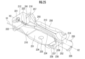
- 13 is a perspective view of the catheter connector of FIG. 12 from another angle.
- FIG. 11 is a perspective view of a catheter connector according to a third embodiment of the present invention.
- 27 is a perspective view of the catheter connector of FIG. 26 from another angle.
- FIG. 27 is a front view of the catheter connector of FIG. 26.
- FIG. 27 is a top view of the first member of FIG. 26; FIG.
- FIG. 27 is a side cross-sectional view of the third member of FIG. 26 .
- 27 is a perspective view of the catheter connector of FIG. 26 from another angle.
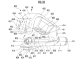
- FIG. 10 is a perspective view of a catheter connector according to a fourth embodiment of the present invention.
- 33 is a perspective view of the catheter connector of FIG. 32 from another angle.
- 33 is a side view showing the catheter connector of FIG. 32 in a fully fixed state.
- FIG. 33 is a front view of the catheter connector of FIG.
- FIG. 33 is a side cross-sectional view of the catheter connector of FIG. This is a cross-sectional view taken along line XXXIV-XXXIV of Figure 34.
- 33 is a side view showing the temporarily fixed state of the catheter connector of FIG. 32.
- FIG. 1 is a perspective view showing the catheter connector 100 with the catheter 10 attached
- Figure 2 is a perspective view showing the catheter connector 100 when the catheter 10 is attached or detached
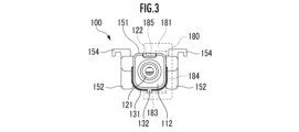
- Figure 3 is a front view of the catheter connector 100.
- the third member 180 is shown by a dashed line so that the shapes of the first member 110 and the second member 150 can be easily understood.
- the catheter connector 100 is formed in the longitudinal direction along the direction in which the catheter 10 is connected, and has a central axis X1.
- the catheter connector 100 includes a first member 110, a second member 150, and a third member 180.
- the tip portion of the catheter 10 is inserted into the catheter connector 100, and is further wrapped around and held on the upper part of the catheter connector 100.
- the catheter connector 100 will be described in a state in which the catheter 10 can be inserted or removed.
- the first member 110 and the second member 150 have their ends connected to each other and rotate relative to each other with the connected part as the center of rotation.
- the engagement direction in which the second member 150 approaches the first member 110 is the L direction
- the disengagement direction in which the second member 150 moves away from the first member 110 is the M direction.
- the catheter 10 is inserted or removed in the state shown in FIG. 2, that is, in the state in which the second member 150 is rotated and opened relative to the first member 110.
- the catheter 10 inserted in the first member 110 is not subjected to a pressing force from the second member 150. Therefore, the catheter 10 can be easily inserted into and removed from the first member 110 when the second member 150 is open.
- the configuration of the first member 110 will be described with reference to Figures 2 and 4.
- Figure 4 is a top view of the first member 110.
- the first member 110 is a member to which the catheter 10 and an infusion device (not shown) are respectively connected.
- the first member 110 is integrally formed from resin.
- the configuration of the first member 110 as viewed from the top surface 111 side will be described with reference to FIG. 4.
- the first member 110 has one end 112, which is the end to which the catheter 10 is connected, the other end 114, which is the end opposite the one end 112, and an intermediate portion 113 provided between the one end 112 and the other end 114.
- a cylindrical member 120 is provided by insert molding on the top surface 111, which is the surface of the first member 110 that contacts the second member 150.
- the central axis of the cylindrical member 120 is the central axis X1 of the catheter connector 100, and the cylindrical member 120 is provided from the one end 112 to the end on the other end 114 side of the intermediate portion 113.
- the one end 112 is one end side of the tubular member 120 formed inside the first member 110, and is provided with a catheter insertion section 121 into which the tip of the catheter 10 is inserted.
- the catheter insertion section 121 is provided with its center aligned with the central axis X1 of the catheter connector 100.
- the catheter insertion section 121 is a generally conical hole with a large diameter at the entrance side and a gradually smaller diameter toward the inside.
- the catheter insertion section 121 is formed with a larger diameter at the entrance side than at the back side, so that the tip of the catheter 10 can be easily inserted.
- An engagement groove 122 is provided on the upper surface of the one end 112 and is formed with a constant width along the central axis X1 of the catheter connector 100.
- a space 115 is provided on the other end 114 side of the one end 112.
- the space 115 is a space for injecting the material of the tubular member 120 formed by insert molding.
- the space 115 is formed across the entire width of the catheter connector 100, which is perpendicular to the central axis X1 of the catheter connector 100.
- the intermediate section 113 has an engagement base 116 at one end 112 of the intermediate section 113, and a connection base 117 at the other end 114 of the intermediate section 113.
- the connection base 117 may be translucent to such an extent that the catheter 10 can be seen from above.
- a part of the catheter 10 when the catheter 10 is inserted into the body to the appropriate position for injecting the drug solution into the body, a part of the catheter 10 may be colored in two places: a region R1 that can be seen from the top of the connection base 117, and a region R2 that is near the entrance of the catheter insertion section 121 and can be seen from above.
- the user can see the colored parts of the catheter 10 from above through the region R1 of the connection base 117 and the region R2 near the entrance of the catheter insertion section 121, and recognize that the catheter 10 has been inserted to the appropriate position when inserted into the body.
- the engagement base 116 is provided perpendicular to the upper surface 111.
- the engagement base 116 is a member that maintains the second member 150 in a closed state when the second member 150 is closed.
- engagement parts 123 are formed at both ends in the width direction of the engagement base 116, protruding toward the other end 114.
- an engagement groove 124 is provided that is formed with a constant width along the central axis X1 direction of the catheter connector 100.
- the catheter connector 100 When disengaging the engaging portion 123 from the locking portion 155, hold the one end 112 and the other end 114 with your fingers and bend the intermediate portion 113 between them so that it is convex upward. Then, the catheter connector 100 elastically deforms into an upwardly convex arc, and the locking portion 155 shifts from its fixed position and disengages from the engaging portion 123. That is, the locking portion 155 can move relatively in the engagement direction (L direction in FIG. 2) in which it approaches the engaging portion 123, and in the disengagement direction (M direction in FIG. 2) in which it moves away from the engaging portion 123, and can releasably engage with the engaging portion 123.
- the user can easily engage and disengage the first member 110 and the second member 150, and fix the catheter 10 with a single touch.
- the catheter connector 100 reduces differences in how users use it, improves the prevention performance of catheter kinking and dislodging, and improves usability.
- connection base 117 has shafts 125 formed to protrude perpendicularly to the central axis X1 direction from both side surfaces of the catheter connector 100 that are parallel to the central axis X1 direction.
- the shafts 125 fit into corresponding portions of the second member 150 and are parts that hold the second member 150 rotatably.
- the other end 114 is the part to which an infusion device is connected, and as shown in FIG. 2, has a threaded ridge 126 to be connected to the infusion device.
- the threaded ridge 126 has a shape corresponding to the infusion device to be connected, and may be formed as a female connection part conforming to the ISO 80369-6 standard.
- An upstream device for epidural anesthesia such as an anesthesia filter, is connected to the other end 114.
- Two threaded ridges 126 are provided at equal intervals in the circumferential direction on the circumference adjacent to the end face of the other end 114.
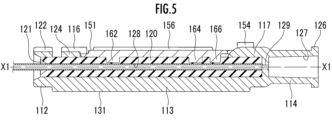
- FIG. 5 is a side cross-sectional view showing the catheter connector 100 in a state in which the second member 150 is closed by the first member 110. As shown in FIG. 5, the other end 114 has a connection hole 127 inside that is open on the end face side.
- the tubular member 120 is provided from the catheter insertion portion 121 at one end to the other end, and has a catheter insertion hole 128 that communicates with the connection hole 127.
- the central axis of the tubular member 120 is the central axis X1 of the catheter connector 100.
- the tubular member 120 is formed of a transparent material or an elastically deformable material that is colored to be opaque by mixing with a pigment, for example, a thermosetting elastomer (e.g., silicone rubber, fluororubber), a thermoplastic elastomer (e.g., styrene-based thermoplastic elastomer, olefin-based thermoplastic elastomer, vinyl chloride-based thermoplastic elastomer).
- a thermosetting elastomer e.g., silicone rubber, fluororubber
- a thermoplastic elastomer e.g., styrene-based thermoplastic elastomer, olefin-based thermoplastic elastomer, vinyl chloride-based thermoplastic elastomer.
- the lower surface 131 of the first member 110 is provided with a guide portion 132.
- the guide portion 132 is a portion along which the inner surface of the third member 180 slides and guides when the third member 180 described later is attached.
- the guide portion 132 is a protrusion, and is provided in the center of the width direction perpendicular to the central axis X1 direction of the catheter connector 100 on the lower surface 131, from one end 112 to the other end 114, parallel to the central axis X1.
- the number of guide portions 132 may be two or more as long as the third member 180 can slide stably when attached. The more guide portions 132 there are, the stronger the catheter connector 100 will be.
- a plurality of protrusions 133 are provided on three surfaces, the lower surface 131 and both side surfaces of the first member 110.
- Four protrusions 133 are provided along the central axis X1 direction of the catheter connector 100.
- the ridges 133 prevent the user's fingers from slipping when holding the catheter connector 100.
- the number of ridges 133 may be other than four, for example, one to three, or five or more. The more ridges 133 there are, the stronger the catheter connector 100 will be.
- the configuration of the second member 150 will be described with reference to Figures 1 to 3 and Figure 5.
- the second member 150 is a member that presses and holds the catheter 10 via the tubular member 120 in a closed state, and also wraps around and holds the middle part of the catheter 10.
- the second member 150 is in contact with the upper surface 111 of the first member 110.
- the outer surface of the second member 150 and the outer surface of the first member 110 adjacent to the second member 150 are configured to form a continuous surface with almost no steps.
- the second member 150 is rotatable around the axis 125 of the first member 110 to which it is connected.
- the second member 150 is integrally formed from resin.
- the configuration of the upper surface 151 of the second member 150 will be described with reference to FIG. 1.
- the second member 150 is an elongated plate-like member overall, and the other end 114 side of the second member 150 is bifurcated into a Y-shape, with each end being provided with a connecting portion 152.
- Each connecting portion 152 has an axial hole 153 into which the shaft 125 of the first member 110 is fitted, so that the second member 150 is rotatably held by the first member 110.
- a catheter locking portion 154 which is a rectangular plate member, is provided on the upper portion of each of the pair of connecting portions 152. The catheter locking portion 154 is formed to protrude vertically from the upper portion of each connecting portion 152 in the direction of the central axis X1 of the catheter connector 100.
- the upper surface 151 is provided with guide portions 156 parallel to the central axis X1 of the catheter connector 100.
- the guide portions 156 are two ridges that are provided parallel to each other at a certain interval from one end 112 to the other end 114, and define a sliding surface 157 located between them.
- the guide portions 156 guide the third member 180 by pinching it from both sides when the contact portion of the third member 180 slides on the sliding surface 157.
- the number of guide portions 156 may be three or more as long as they can guide the third member 180.
- the strength of the catheter connector 100 is improved by increasing the number of guide portions 156.
- a locking portion 155 is provided over the entire width of the upper surface 151 on the one end 112 side of the second member 150.
- Figure 6 is a bottom view of the second member 150.
- Figures 7 to 9 are cross-sectional views taken along lines VII-VII, VIII-VIII, and IX-IX of Figure 6, respectively. Note that Figures 7 to 9 are cross-sectional views of the underside 161 of the second member 150 facing downward, and the background portion is omitted.
- the second member 150 has a first pressing portion 162, a second pressing portion 164, and a third pressing portion 166.
- the above pressing portions are arranged in the order of the first pressing portion 162, the second pressing portion 164, and the third pressing portion 166, in the center of the width direction of the lower surface 161 of the second member 150 from the one end portion 112 side to the other end portion 114 side.
- the first pressing portion 162 is arranged around the one end portion 112 side of the lower surface 161, and the second pressing portion 164 and the third pressing portion 166 are arranged around the other end portion 114 side of the lower surface 161.
- FIG. 7 shows a cross-sectional view of the first pressing portion 162.
- the first pressing portion 162 has a pressing surface 163 formed in a flat surface.
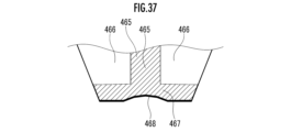
- FIG. 8 shows a cross-sectional view of the second pressing portion 164.
- the second pressing portion 164 has a pressing surface 165 formed in a concave surface that extends along the central axis X1 of the catheter connector 100.
- the third pressing portion 166 has two protrusions 167 formed to protrude downward from the lower surface 161. As shown in FIG. 6 and FIG. 9, the two protrusions 167 are formed in a plate shape and are arranged parallel to the central axis X1 direction of the catheter connector 100 and spaced apart from each other.
- the two protrusions 167 each have a pressing surface 168 formed in a flat surface on the surface facing each other, i.e., the inner surface.
- a pressing surface 169 is provided that is formed in a flat surface and is a part of the lower surface 161 of the third pressing portion 166.
- the inside of the third pressing portion 166 forms a space surrounded by three flat surfaces by the pressing surface 169, which is a horizontal surface, and the pressing surfaces 168, which are two vertical surfaces.
- the third pressing portion 166 is a portion that maintains airtightness between the catheter 10 and the inner surface of the insertion hole 128 in the insertion hole 128 of the catheter 10. Therefore, the third pressing portion 166 is formed to cover both side surfaces of the tubular member 120 so that a part of the outer periphery of the pressed tubular member 120 does not escape to the outside.
- the lower surface side of the tubular member 120 is held by the first member 110, and when the second member 150 is closed, the side and upper surface of the tubular member 120 are pressed against the second member 150.
- the second pressing portion 164 firmly holds the pressed portion of the tubular member 120 so that it does not escape from the pressing range of the second pressing portion 164. For this reason, the pressing surface 165 is formed into a concave curved surface that makes surface contact with the shape of the tubular member 120.
- the first pressing portion 162 reinforces the pressing force that presses the tubular member 120. Therefore, the pressing surface 163 is formed flat so as to make point contact with the outer surface of the tubular member 120.
- the above-mentioned pressing parts press the tubular member 120, and as a result, the catheter 10 inserted into the catheter insertion hole 128 of the tubular member 120 is pressed by the inner surface of the catheter insertion hole 128. Since the catheter connector 100 is used with the second member 150 closed, the catheter 10 is always held in place so that it does not come off the first member 110 during use.
- the above pressing parts are provided with a first pressing part 162, a second pressing part 164, and a third pressing part 166, but may be other than the above.
- only one or two of the above pressing parts may be provided.
- the first pressing part 162 and the second pressing part 164 are spaced apart from each other in a direction parallel to the central axis X2.
- the first pressing part 162 and the second pressing part 164 may be extended in a direction parallel to the central axis X2 to form a continuous single pressing part. This increases the pressing area, and therefore the pressing force on the catheter 10 can be increased.
- all two or all three of the above pressing parts may have the same shape.
- An infusion device is connected to the other end 114, and a connection hole 127 is formed as an inlet for medicinal fluids and the like.
- a communication hole 129 is provided on the one end 112 side of the connection hole 127, which is connected to the connection hole 127 and has a diameter slightly smaller than the outer diameter of the catheter 10. The catheter 10 inserted from the catheter insertion section 121 is inserted in a state where it is aligned with the central axis of the communication hole 129 until it hits the surface of the one end 112 side of the wall section in which the communication hole 129 is formed. In the embodiment shown in FIG.
- the position of the end face of the catheter 10 on the other end 114 side in the direction of the central axis X1 is the same as the position of the end face of the tubular member 120.
- the third pressing section 166 presses while surrounding the outer circumferential surface of the tubular member 120. Therefore, there is almost no gap between the inner surface of the catheter insertion portion 128 inside the catheter 10 and the outer surface of the catheter 10, and the medicinal solution or the like that flows into the connection hole 127 is injected into the catheter 10 without leaking out to the outside of the catheter 10.
- the position of the end face of the tubular member 120 on the other end 114 side in the direction of the central axis X1 may be on the one end 112 side from the position of the end face of the catheter 10, and the tip of the catheter 10 on the other end 114 side may protrude from the tubular member 120.
- the catheter 10 can be visually confirmed through the first member 110 formed of a transparent or translucent material that is colored to be opaque by mixing a pigment, and the tip position of the catheter 10 can be confirmed.
- the above configuration is expected to improve moldability.
- the operation feeling generating section will be described with reference to Figures 10 and 11.
- the operation feeling generating section is a section that allows the user to perceive that the second member 150 is at a predetermined rotation angle position relative to the first member 110 when the second member 150 is opened or closed.
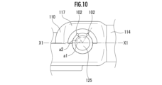
- Figure 10 is a partial side view taken along arrow D in Figure 4.
- Figure 11 is a partial side view taken along arrow E in Figure 6, with one end 112 side facing right and the top surface 151 facing upward.
- one or more protrusions 102 are provided on the outer peripheral surface of one of the shafts 125 provided on the first member 110. That is, the first member 110 and the second member 150 face each other, and both surfaces perpendicular to the rotation axis have an operation feeling generating portion.
- the one or more protrusions 102 are provided at intervals in the circumferential direction on the outer peripheral surface of the shaft 125 at a position adjacent to the connection part 152 of the second member 150.
- a protrusion 103 is provided at a position adjacent to the shaft hole 153 on the surface of the connection part 152 on the side adjacent to the protrusion 102 of the second member 150, on the connection base part 117 side.
- the positions and protrusion amounts of the protrusions 102 and 103 are determined so that they come into contact with each other at a specific angle when the second member 150 rotates relative to the first member 110.
- the protrusion 102 provided on the first member 110 and the protrusion 103 provided on the second member 150 are operation sensation generating parts. Note that one or three protrusions 102 may be provided.
- the center position of the shaft 125 and the center position of the shaft hole 153 are points on a horizontal plane passing through the central axis X1 of the catheter connector 100.
- the protrusion 103 is provided on the surface of the connecting part 152 that contacts the protrusion 102 at a position where the horizontal plane passing through the central axis X1 intersects, and at a portion adjacent to the one end 112 side of the shaft hole 153.
- the protrusion 102 is provided in two places.
- the protrusion 102 is provided at angles a1 and a2 with the central axis X1 set at 0 degrees.
- the angle a1 is in the range of about 40 degrees to about 60 degrees, for example, about 50 degrees.
- the angle a2 is in the range of about 110 degrees to about 130 degrees, for example, about 120 degrees.
- an opening angle of about 40 degrees to about 60 degrees at which each pressing part such as the first pressing part 162 moves away from the tubular member 120 is convenient.
- an opening angle of approximately 120 degrees, in which the second member 150 is in a nearly fully open position is convenient.
- the protrusion 103 of the second member 150 passes over the protrusion 102 of the first member 110. At that time, the user can feel a clicking sensation. Therefore, the user can know the degree of opening of the second member 150 just by the sense of operating with his/her hand without visually checking, and can proceed with the work efficiently. Furthermore, the protrusion 103 cannot rotate past the protrusion 102 unless the user rotates it, so the operation feeling generating unit can maintain the second member 150 at a predetermined angle relative to the first member 110. The second member 150 can be kept open even if the user does not hold the second member 150 with his/her hand, and the user can efficiently proceed with the work of attaching the catheter 10, cleaning the catheter connector 100, and so on.
- protrusions 102 and 103 can be provided at any desired rotation angle position.
- two sets of protrusions 102 and 103 may be provided, one on each side of connection base 117 and the other on the opposing side.
- the third member 180 will be described with reference to Figures 1 and 3.
- the third member 180 is a member that maintains the first member 110 and the second member 150 in a closed state.
- the third member 180 is a member with a U-shaped cross section, and is attached to the side of the first member 110 and the second member 150 in the closed state, holding them by sandwiching them from above and below.
- the third member 180 can prevent the first member 110 and the second member 150 from opening unintentionally.
- the third member 180 can cover and hold at least a portion of the catheter 10 attached to the catheter connector 100.
- the third member 180 is attached to the first member 110 and the second member 150, which are in an engaged state, by sliding from one end 112 of the first member 110 in the N direction in FIG. 1, which is parallel to the central axis X1 direction.
- the third member 180 is a member whose cross section perpendicular to the central axis X1 is substantially U-shaped.
- the third member 180 has an upper plate portion 181, a lower plate portion 183, and a side plate portion 184, each of which is formed in a rectangular plate shape.
- One end of the upper plate portion 181 is connected along the upper end of the side plate portion 184, and one end of the lower plate portion 183 is connected along the lower end of the side plate portion 184.
- a sliding rib 185 is formed on the upper plate portion 181 over the entire length at the end opposite the side plate portion 184.
- the sliding rib 185 is formed in a downward semicircular shape in a cross section perpendicular to the central axis X1.
- the upper surface of the lower plate portion 183 i.e., the surface on the first member 110 side, is formed flat, and when the third member 180 is attached, the rib 132 formed on the lower surface 131 of the first member 110 comes into contact with it.
- the third member 180 When the third member 180 is attached to the catheter connector 100, one end of the sliding protrusion 185 provided on the upper plate portion 181 is fitted into the engagement groove 122 of the first member 110, and the third member 180 is attached by sliding it along the engagement groove 124 and the sliding surface 157.
- the method of attaching the catheter 10 to the catheter connector 100 will be described with reference to FIG. 1.
- the second member 150 is opened, the tip of the catheter 10 is inserted into the catheter insertion section 121 until it hits the end, and the second member 150 is closed.
- the middle part of the catheter 10 is hooked successively to one of the catheter locking sections 154 and then to the other.
- the catheter 10 is aligned along the side of the one end 112, and the third member 180 is attached so as to cover part of the middle part of the catheter 10. In this manner, the catheter 10 is attached to the catheter connector 100.
- the above procedure is reversed.
- the configuration of a catheter connector 200 according to a second embodiment of the present invention will be described with reference to Figures 12 to 15.
- the catheter connector 200 has three members similar to the catheter connector 100 according to the first embodiment, but each member has a different shape.
- the catheter connector 200 will be described below. Note that the catheter connector 200 has the same shape or structure as the catheter connector 100, and the same reference numerals will be used and the description thereof will be omitted.
- Figure 12 is a perspective view of the catheter connector 200 with the catheter 10 attached
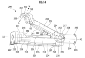
- Figure 14 is a perspective view of the catheter connector 200 when the catheter 10 is being attached or detached
- Figure 15 is a front view of the catheter connector 200.
- the third member 280 is shown by a dashed line so that the shapes of the first member 210 and the second member 250 can be easily understood.
- the catheter connector 200 is formed in the longitudinal direction along the direction in which the catheter 10 is connected, and has a central axis X2.
- the catheter connector 200 includes a first member 210, a second member 250, and a third member 280.
- the tip of the catheter 10 is inserted into the catheter connector 200, and is further held by being wrapped around the lower part of the catheter connector 200.
- the catheter connector 200 in a state in which the catheter 10 can be inserted or removed will be described.
- the first member 210 and the second member 250 have their ends connected to each other, and rotate relatively around the connected part as the center of rotation.
- the engagement direction in which the second member 250 approaches the first member 210 is the L direction
- the disengagement direction in which the second member 250 moves away from the first member 210 is the M direction.
- the catheter 10 is inserted or removed in the state shown in FIG. 14, that is, in the state in which the second member 250 is rotated and opened relative to the first member 210.
- the catheter 10 inserted in the first member 210 is not subjected to a pressing force from the second member 250. Therefore, the catheter 10 can be easily inserted and removed from the first member 210 when the second member 250 is open relative to the first member 210.
- Figures 12 and 15 show the third member 280 of the catheter connector 200.
- the third member 280 is a member with a U-shaped cross section, and is attached so as to surround the first member 210 and the second member 250 to prevent them from opening unintentionally.
- Figure 16 is a top view of the first member 210.
- the first member 210 is a member to which the catheter 10 and an infusion device (not shown) are respectively connected.
- the first member 210 is integrally formed from resin.
- the first member 210 has one end 212, which is the end to which the catheter 10 is connected, the other end 214, which is the end opposite to the one end 212, and an intermediate portion 16 provided between the one end 212 and the other end 214.
- a cylindrical member 220 is provided by insert molding on the top surface 211, which is the surface of the first member 210 that contacts the second member 250. As shown in FIG. 18, the cylindrical member 220 is provided with an undercut shape 220b to prevent the core pin from falling off during molding.
- the central axis of the cylindrical member 220 is the central axis X2 of the catheter connector 200, and the cylindrical member 220 is provided from the one end 212 to the end on the other end 214 side of the intermediate portion 213.
- the one end 212 is one end of the tubular member 220 disposed inside the first member 210, and is provided with a catheter insertion section 221 into which the tip of the catheter 10 is inserted.
- the catheter insertion section 221 is formed so that the diameter is large on the entrance side and gradually decreases toward the inside.
- the catheter insertion section 221 is defined by an inner surface 221a of a convex curved surface, such as the side of an approximately truncated cone bulging outward over the entire circumference.
- the catheter insertion section 221 is provided with its center coinciding with the central axis X2 of the catheter connector 200.
- the catheter insertion section 221 is formed so that the diameter on the entrance side is larger than the diameter on the back side, so that the tip of the catheter 10 can be easily inserted.
- the entrance side of the tubular member 220 is defined by an inner surface 220a of a convex curved surface, such as the side of an approximately truncated cone bulging outward over the entire circumference.
- the inner surface 221a of the catheter insertion section 221 and the inner surface 220a of the tubular member 220 are smoothly continuous, and are formed in a generally horn shape in which the diameter gradually increases in the direction from the tubular member 220 toward the catheter insertion section 221 (leftward in FIG. 18), and the rate of increase in the diameter gradually increases.
- each engagement groove 222 is formed upward from the lower end surface of the one end 212, i.e., toward the central axis X2 side.
- the lower end of the one end 212 protrudes downward from the lower surface 231 of the first member 210. This allows the user to easily fit the catheter 10 into the engagement groove 222.
- a space 215 is provided on the side of the other end 214 of the one end 212.
- the space 215 is a space into which a part of the second member 250 is inserted to keep the second member 250 in a closed state, as described below.
- the intermediate portion 213 has an engagement base 216 at one end 212 of the intermediate portion 213, and a connection base 217 at the other end 214 of the intermediate portion 213.
- the engagement base 216 includes a portion whose cross section in a side view is formed into an approximately triangular prism shape, and is disposed on the upper surface 211 with the central axis of the approximately triangular prism shape oriented perpendicular to the central axis X2 of the catheter connector 200.
- the engagement base 216 is connected to one end 212 by engagement portions 241 provided at both ends of the engagement base 216 in the width direction.
- the space 215 is formed by being surrounded by the one end 212 and the engagement base 216 in a top view.
- the engagement base 216 has a slope 242 extending perpendicular to the central axis X2. When the second member 250 is closed, the slope 242 comes close to or directly contacts the corresponding surface of the second member 250 with a small gap.
- the engaging base 216 has guide portions 239, which are protrusions formed parallel to the central axis X2, on both side surfaces.
- the guide portions 239 guide the sliding movement of the third member 280 in the direction of the central axis X2, i.e., in the N direction in FIG. 12, relative to the first member 210 and second member 250, which are in an engaged state.
- mating protrusions 243 are provided on both ends in the width direction on the top surface 211.
- the mating protrusion 243 is formed in a deformed pentagon in top view, with one corner of a rectangular parallelepiped cut off by a flat surface.
- the mating protrusion 243 fits into a corresponding recess in the second member 250, and holds the first member 210 and the second member 250 in place to prevent misalignment.
- connection base 217 has shafts 225 formed to protrude perpendicularly to the central axis X2 direction from both side surfaces parallel to the central axis X2 direction of the catheter connector 200.
- the shafts 225 are fitted into corresponding parts of the second member 250 and hold the second member 250 rotatably.
- the connection base 217 has a substantially rectangular part in a top view and a protruding part that protrudes locally to the left from the substantially rectangular part.
- the protruding part of the connection base 217 in FIG. 16 may be omitted so that the tubular member 220 is visibly exposed from the top surface. This prevents or suppresses the occurrence of sink marks and voids in the protruding part during molding of the connection base 217, thereby improving the moldability of the connection base 217.
- the other end 214 is the part to which an infusion device is connected, and has a threaded ridge 226 that is connected to the infusion device as shown in FIG. 14, and also has a connection hole 127 inside the other end 214.
- the other end 214 has a similar shape to the other end 114 of the first embodiment, and the structure and effects are the same as those of the other end 114 of the first embodiment, so a description thereof will be omitted.
- the configuration of the tubular member 220 provided on the upper surface 211 of the first member 210 will be described.
- One end of the tubular member 220 is a catheter insertion section 221, and the other end has a catheter insertion hole 228 that communicates with the connection hole 127.
- the tubular member 220 is formed of an elastically deformable material, such as a rubber tube.
- the end of the tubular member 220 on the one end 212 side penetrates the engagement base 216 and is inserted into the one end 212, and the end of the tubular member 220 on the other end 214 side is inserted into the connection base 217 and fixed. In other words, the tubular member 220 is fixed to the first member 210 at each of the above-mentioned fixing points.
- the cylindrical member 220 has an enlarged diameter portion (not shown) whose outer diameter is slightly larger than the other portions at each of the above-mentioned fixing points fixed to the first member 210, around the entire circumference of the cylindrical member 220.
- the enlarged diameter portion prevents the cylindrical member 220 from shifting in the direction of the central axis X2 relative to the first member 210.
- the first member 210 is molded with resin, enveloping each enlarged diameter portion at each of the above-mentioned fixing points. Each enlarged diameter portion only needs to be molded with enough strength to prevent shifting in the direction of the central axis X2.
- each enlarged diameter portion is about 110% to 130% of the outer diameter of the portion of the cylindrical member 220 excluding the enlarged diameter portion, for example, 115% to 125%.
- the enlarged diameter portion provided in the one end portion 212 may be provided on the end surface of the cylindrical member 220 on the one end portion 212 side. The outer surface of the cylindrical member 220 other than the portion covered by the first member 210 is exposed from the first member 210.
- the tubular member 220 and its surrounding parts are similar in structure to the tubular member 120 and its surrounding parts of the first embodiment shown in the side cross-sectional view of FIG. 5, so refer to FIG. 5 and omit the side cross-sectional view of the second embodiment.
- the tubular member 220, catheter insertion section 221, catheter insertion hole 228, engagement base 216, and connection base 217 in the second embodiment correspond to the tubular member 120, catheter insertion section 121, catheter insertion hole 128, engagement base 116, and connection base 117 in the first embodiment of FIG. 5, respectively.
- the configuration of the lower surface 231 of the first member 210 will be described with reference to FIG. 14.
- the lower surface 231 of the first member 210 is provided with a protrusion 234.
- the protrusion 234 is formed to protrude horizontally so as to extend both ends in the width direction of the lower surface 231, which is formed as a flat surface.
- An injection hole 235 is provided approximately near the center of the lower surface 231.
- the injection hole 235 is formed through the first member 210 and is a hole for injecting material for the cylindrical member 220 formed by insert molding from the lower surface 231. Note that, in addition to a method in which the cylindrical member 220 is molded by injecting material from the injection hole 235 after molding the first member 210, the cylindrical member 220 may be molded first and then the first member 210 may be insert molded.
- the lower surface 231 of the first member 210 on the other end 214 side i.e., the lower surface of the connection base 217
- the step surface 236 is provided with a catheter winding section 237 protruding downward from the step surface 236.
- the lower surface, which is the tip portion on the protruding side of the catheter winding section 237, is formed as an inclined surface, and the one end 212 side is at the same height as the lower surface 231, and is formed to protrude downward toward the other end 214 side.
- the lower part of the catheter winding section 237 is formed to protrude downward from the lower surface 231.
- guide sections 238 are provided at both ends of the step surface 236 in the width direction, perpendicular to the step surface 236 and protruding downward, and formed at approximately the same height as the lower surface 231.
- the configuration of the second member 250 will be described with reference to Figures 12 to 14 and Figure 19.
- the second member 250 is a member that presses and holds the catheter 10 via the tubular member 220 in the closed state.
- the second member 250 when the second member 250 is in the closed state, the second member 250 is in contact with the upper surface 211 of the first member 210. As shown in FIG. 14, the second member 250 is rotatable about the axis 225 of the first member 210 to which it is connected.
- the second member 250 is integrally formed from resin.
- the second member 250 is an elongated plate-like member as a whole, and the other end 214 side of the second member 250 is bifurcated into a Y-shape, and each end 214 side is provided with a connecting portion 252. As shown in FIG. 13, the second member 250 may be provided with a visor portion 227 extending between the two connecting portions 252 and having a closed shape so that at least a part of the cylindrical member 220 is not visibly exposed from the top surface.
- each connecting portion 252 has an axial hole 253, and the shaft 225 of the first member 210 is fitted into the axial hole 253, so that the second member 250 is rotatably held by the first member 210.
- the one end 212 side of the second member 250 is also bifurcated into a Y-shape, and each end 212 side is provided with a locking base 257.
- the side of the connection part 252 is formed so that the lower half protrudes from the horizontal plane passing through the center of the shaft hole 253 relative to the upper half.
- the upper surface of the protruding lower half of the connection part 252 serves as a guide part 254 on both sides of the shaft hole 253.
- the guide part 254 is a part that guides the sliding movement of the third member 280 when the third member 280 is attached.
- the locking base 257 is formed in a complex shape that is bent at multiple points.
- the locking base 257 extends from the one end 212 side of the second member 250 toward the one end 212 side, its tip extends in the direction of the central axis X2, and its tip extends again toward the one end 212 side, and a tip portion extending downward is formed at its tip.
- the tip portions are provided with locking portions 258 that protrude outward in a direction perpendicular to the central axis X2.
- the locking portions 258 are located at a position that overlaps with the space portion 215 in a top view.
- the locking base 257 When the second member 250 is closed, the locking base 257 is inserted into the space portion 215 while bending toward the central axis X2, and the locking portions 258 engage with the engagement portions 241.
- the upper surface 251 is provided with a protrusion 256 that has an arc-shaped cross section along the central axis X2.
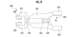
- Figure 19 is a bottom view of the second member 250.
- the second member 250 has a first pressing portion 162, a second pressing portion 164, and a third pressing portion 166, similar to the second member 150 of the first embodiment.
- the shape, cross section, respective arrangement, and effect of each of the above pressing portions are the same as those of the second member 150 of the first embodiment.
- the configuration of the tubular member 220 of the catheter connector 200 and its surrounding parts is similar to the tubular member 120 of the first embodiment and its surrounding parts.
- a connection hole 127 is formed in the other end 114.
- a communication hole 129 that is connected to the connection hole 127 and has a diameter slightly smaller than the outer diameter of the catheter 10 is provided on the one end 212 side of the connection hole 127.
- the internal structure of the catheter connector 200 and the flow of medicinal fluids and the like within the catheter connector 200 from the connection hole 127 to the catheter 10 are similar to those of the catheter connector 100 of the first embodiment.
- the flow of medicinal fluids and the like to the catheter 10 in the catheter connector 200 will be explained by combining the overall view of the catheter connector 200 in FIG. 14 with the peripheral portion of the connection hole 127 in FIG. 5, which has the same structure as the peripheral portion of the connection hole 127 in the catheter connector 200.
- the various symbols will be interpreted as follows.
- the first member 110 will be interpreted as the first member 210, the second member 150 as the second member 250, the one end 112 as the one end 212, the other end 114 as the other end 214, the catheter insertion portion 121 as the catheter insertion portion 221, and the central axis X1 as the central axis X2.
- An infusion device such as a syringe is connected to the connection hole 127.
- a communication hole 129 is provided on the one end 212 side of the connection hole 127, which communicates with the connection hole 127 and has a diameter slightly smaller than the outer diameter of the catheter 10.
- the catheter 10 inserted from the catheter insertion section 221 is inserted in a state where it is aligned with the central axis X2 of the communication hole 129 until it hits the surface of the one end 212 side of the wall section in which the communication hole 129 is formed.
- the position of the end face of the catheter 10 on the other end 214 side in the direction of the central axis X2 is the same as the position of the end face of the tubular member 220.
- the third pressing section 166 presses while surrounding the outer peripheral surface of the tubular member 120. Therefore, there is almost no gap between the inner surface of the catheter insertion portion 128 inside the catheter 10 and the outer surface of the catheter 10, and the medicinal liquid or the like that flows into the connection hole 127 is injected into the catheter 10 without leaking out to the outside of the catheter 10.
- the position of the end face of the cylindrical member 220 on the other end 214 side in the direction of the central axis X2 may be on the one end 212 side from the position of the end face of the catheter 10, and the tip of the catheter 10 on the other end 214 side may protrude from the cylindrical member 220. With this configuration, the catheter 10 can be visually confirmed through the first member 210 formed of a transparent or colored translucent material, and the tip position of the catheter 10 can be confirmed. In addition, the above configuration is expected to improve moldability.
- the operation feeling generating section will be described with reference to Figures 20 and 21.
- the operation feeling generating section is a section that allows the user to perceive that the second member 250 is at a predetermined rotation angle position relative to the first member 210 when the second member 250 is opened or closed.
- Figure 20 is a partial side view taken along arrow F in Figure 16.
- Figure 21 is a partial side view taken along arrow G in Figure 19, with one end 212 facing right and the top surface 251 facing upward.
- a cylindrical protrusion 202 is provided on one side of the connection base 217 on which the shaft 225 of the first member 210 is provided.
- a protrusion 203 is provided on the surface of the connection base 217 side of the connection part 252 on the side adjacent to the protrusion 202 of the second member 250, adjacent to the shaft hole 253, and formed linearly in the radial direction from the center of the shaft hole 253. The positions and protrusion amounts of the protrusions 202 and 203 are determined so that they come into contact with each other at a specific angle when the second member 250 rotates relative to the first member 210.
- the protrusion 202 provided on the first member 210 and the protrusion 203 provided on the second member 250 are operation feeling generating parts.
- the first member 210 and the second member 250 have operation feeling generating parts on both surfaces that face each other and are perpendicular to the rotation axis.
- the center position of the shaft 225 and the center position of the shaft hole 253 are points on a horizontal plane passing through the central axis X2 of the catheter connector 200. If a plane passing through the center of the shaft 225 and perpendicular to the central axis X2 is Z2, the protrusion 202 is located at a position rotated by angle a3 from the vertical plane Z2 with the center of the shaft 225 as the center of rotation.
- the vertical plane Z2 coincides with the protrusion 203 when the second member 250 is closed. Therefore, when the second member 250 is rotated by angle a3, the protrusion 202 and the protrusion 203 come into contact.
- the angle a3 is an angle at which the second member 250 is opened at a predetermined angle relative to the first member 210.
- the angle a3 is in the range of about 60 degrees to about 80 degrees, for example about 70 degrees.
- the angle a3 is appropriately determined to be an angle that is convenient for attaching the catheter 10 or cleaning the catheter connector 200.
- two or more protrusions 202 may be provided.
- a total of two sets of protrusions 202 and 203 may be provided on both sides of the connection base 117 and on the opposing sides.
- the protrusion 203 of the second member 250 passes over the protrusion 202 of the first member 210. At that time, the user can feel a clicking sensation. Therefore, the user can know the degree of opening of the second member 150 just by the sense of operating with his/her hand without visually checking, and can proceed with the work efficiently. Furthermore, the protrusion 203 cannot rotate past the protrusion 202 unless the user rotates it, so the operation feeling generating unit can maintain the second member 250 at a predetermined angle relative to the first member 210. The second member 250 can be kept open even if the user does not hold the second member 250 with his/her hand, and the user can efficiently proceed with the work of attaching the catheter 10, cleaning the catheter connector 200, and so on.
- the attached state of the third member 280 will be described with reference to FIG. 12.
- the third member 280 is a member that maintains the first member 210 and the second member 250 in a closed state.
- the third member 280 is a member with a U-shaped cross section, and is attached so that the first member 210 and the second member 250 do not open unintentionally.
- the third member 280 is attached by sliding, with the opening part of the U-shape facing up, from one end 212 of the first member 210 in the N direction in FIG. 12, which is parallel to the direction of the central axis X2, relative to the first member 210 and the second member 250, which are in an engaged state.
- the third member 280 has a lower plate 283 formed in a substantially rectangular plate shape, and plate-like side plate portions 284 provided vertically on both ends of the lower plate 283.
- Each side plate portion 284 has a protrusion portion 286 that protrudes from the center of the side plate portion 284 in the direction of the central axis X2 and is formed along the direction of the central axis X2.
- Each side plate portion 284 also has a protrusion portion 287 that protrudes in the direction of the central axis X2 from both ends of the side plate portion 284 in the direction of the central axis X2 and is formed along the direction of the central axis X2.
- the lower plate portion 283 has sliding surfaces 288 formed slightly higher than the upper surfaces of the other lower plate portions 283 at both ends in the width direction at both ends in the direction of the central axis X2.
- the lower plate portion 283 has long holes 285 near the center of both ends of the lower plate portion 283 to improve the formability of the third member 280.
- the third member 280 is formed symmetrically with respect to the central axis X2 and a perpendicular line Y2 to the central axis X2 that passes through the center point of the central axis X2 of the third member 280. Therefore, the third member 280 can be attached from either side in the direction of the central axis X2. Therefore, the user does not need to re-hold the third member 280 to adjust its orientation, and can work efficiently.
- the guide portion that guides the third member 280 when the third member 280 is attached will be described.
- the guide portion 238 provided on the underside of the first member 210 and the lower end of the one end 212 slide against the corresponding sliding surface 288 of the third member 280.
- the upper surface of the guide portion 239 and the guide portion 254 slide against the protrusion portion 286 and the protrusion portion 287.
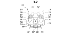
- Figure 24 is a front view of Figure 15 with one end 212 removed.
- the locking base 257 approaches the space 215 of the first member 210.
- the locking portions 258 at the tip portions of the locking base 257 each enter the space 215. Both locking portions 258 bend in the direction of the central axis X2, climbing over the inner surface of the engaging portion 241 and engaging with the underside of the engaging portion 241.
- both outer surfaces of the locking base 257 relative to the central axis X2 are pressed with fingers in a pinching manner to bend both locking portions 258 toward the central axis X2, and both locking portions 258 are disengaged from the respective engagement portions 241 to disengage. That is, the locking portions 258 are movable relative to the engagement portion 241 in the engagement direction (L direction in FIG. 14) in which they approach the engagement portion 241, and in the disengagement direction (M direction in FIG. 14) in which they move away from the engagement portion 241, and can be releasably engaged with the engagement portion 241.
- the user can easily engage and disengage the first member 210 and the second member 250, and fix the catheter 10, with a single touch.
- the catheter connector 200 reduces the difference in usage among users, improves the prevention performance of catheter kinking and dislodging, and improves usability.
- the method of attaching the catheter 10 to the catheter connector 200 will be described.
- the second member 250 is opened, the tip of the catheter 10 is inserted into the catheter insertion section 221 until it hits the end, and the second member 250 is closed.
- the middle part of the catheter 10 is hooked in order into the engagement groove 222 at the lower end of the one end 212, one protruding part 234, the catheter winding section 237, the other protruding part 234, and the other engagement groove 222.
- the catheter 10 is held inside, and the third member 280 is attached while covering at least a part of the catheter 10 with the third member 280. In this manner, the catheter 10 is attached to the catheter connector 200.
- the above procedure is reversed.
- the configuration of the catheter connector 300 according to the third embodiment of the present invention will be described with reference to Figures 26 to 28.
- the catheter connector 300 includes a first member 310, a second member 250, and a third member 380.
- the catheter connector 300 is similar to the catheter connectors 100 and 200 according to the first embodiment in that it includes three members, but the shapes of the corresponding members are different.
- the catheter connector 300 includes a second member 250 that is the same shape as the catheter connector 200 according to the second embodiment, but the shapes of a part of the lower surface of the first member 310 and the third member 380 are different.
- the same parts and structures of the catheter connector 300 as those of the catheter connector 100 or the catheter connector 200 are denoted by the same reference numerals and will not be described.
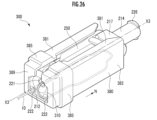
- Figure 26 is a perspective view of the catheter connector 300 with the catheter 10 attached
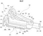
- Figure 27 is a perspective view of the catheter connector 300 when the catheter 10 is being attached or detached
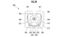
- Figure 28 is a front view of the catheter connector 300.
- the third member 380 is shown with dashed lines so that the shapes of the first member 310 and the second member 250 can be easily understood.
- the catheter connector 300 is formed in the longitudinal direction along the direction in which the catheter 10 is connected, and has a central axis X3. As shown in Figure 26, the tip of the catheter 10 is inserted into the first member 310, and is held by being wrapped around the lower part of the first member 310. In this state, the third member 380 is attached.
- the catheter connector 300 in a state in which the catheter 10 can be inserted or removed will be described.
- the first member 310 and the second member 250 are connected at their ends, and rotate relatively around the connected part as the center of rotation.
- the engagement direction in which the second member 250 approaches the first member 310 is the L direction
- the disengagement direction in which the second member 250 moves away from the first member 310 is the M direction.
- the catheter 10 is inserted or removed in the state shown in FIG. 27, that is, in the state in which the second member 250 rotates and opens relative to the first member 310.
- the catheter 10 inserted in the first member 310 does not receive a pressing force from the second member 250. Therefore, the catheter 10 can be easily inserted and removed from the first member 310 when the second member 250 is open.
- the third member 380 is attached so as to encase the first member 310 and the second member 250 from the outside so that they do not unintentionally open.
- connection base connection base 217 has a substantially rectangular portion in a top view and a protruding portion that locally protrudes to the left from the substantially rectangular portion, but the protruding portion may be omitted as in Figure 17 of the second embodiment.
- the first member 310 has an engagement base 216 on the top surface 211.
- engagement protrusions 243 are provided on both ends in the width direction on the top surface 211.
- the engagement protrusions 243 are formed in a roughly triangular shape when viewed from above.
- the engagement protrusions 243 engage with corresponding recesses in the second member 250 to hold the first member 310 and the second member 250 in place.
- both outer surfaces of the locking base 257 are pressed with the fingers in a pinching motion against the central axis X2 to bend the locking portion 258 and release the engagement. That is, the locking portion 258 is movable relative to the engaging portion 241 in an engagement direction (direction L in FIG. 27) in which it approaches the engaging portion 241, and in a disengagement direction (direction M in FIG. 27) in which it moves away from the engaging portion 241, and can be releasably engaged with the engaging portion 241. Therefore, the user can easily engage and disengage the first member 310 and the second member 250 with a single touch.
- the lower surface 231 of the first member 310 is formed with a catheter winding portion 244 that protrudes in a U-shape from the lower surface 231 in the height direction.
- a groove portion 245 is provided between the catheter winding portion 244 and the lower end portions of both sides of the first member 310.
- the groove portion 245 is disposed at a position overlapping with the engagement groove 222 provided at the lower end portion of the one end portion 212 in a front view.
- the groove portion 245 may be formed as a deep groove on the upper side, i.e., on the central axis X3 side.
- the groove portion 245 may be formed deep over the entire length of the groove portion 245 to a midpoint position in the length between the upper surface 251 and the lower surface 231 of the first member 310, or to a position on the upper surface 251 side of the midpoint position.
- the groove 245 may be formed, for example, at the midpoint of the length between the upper surface 251 and the lower surface 231 on the other end 214 side, and at a depth of about 3/4 of the length between the upper surface 251 and the lower surface 231 on the one end 212 side, so that it gradually becomes deeper from the one end 212 side to the other end 214 side.
- the lower end surface of the one end portion 212 has two engagement grooves 222 formed from the front surface of the one end portion 212 along the central axis X3 of the catheter connector 300, spaced apart in the width direction of the catheter connector 300, which is perpendicular to the central axis X2 of the catheter connector 200.
- Each engagement groove 222 is formed upward from the lower end surface of the one end portion 212, i.e., toward the central axis X3.
- the lower end of the one end portion 212 protrudes downward from the lower surface 231 of the first member 310. This allows the user to easily fit the catheter 10 into the engagement grooves 222.
- a winding protrusion 246 is formed at the end of the catheter winding portion 244 on the other end 214 side.
- the lower surface which is the tip portion of the protruding side of the winding protrusion 246, is formed as an inclined surface.
- the one end 212 side of the winding protrusion 246 is at the same height as the lower surface 231, and is formed to protrude downward as it approaches the other end 214 side.
- the lower part of the winding protrusion 246 is formed to protrude downward from the lower surface 231. This allows the user to easily wind the catheter 10 around the winding protrusion 246.
- a recess 248 that is locally recessed compared to the surrounding area may be formed on the lower surface 231 side of the first member 310.
- the recess 248 is composed of a first recess 248a having a generally bell-like shape (a shape combining a rectangle and a semicircle) with a longitudinal direction parallel to the central axis X3, and a generally rectangular second recess 248b that is continuous with the first recess 248a and is smaller than the first recess, with a longitudinal direction parallel to the central axis X3. That is, the first member 310 is formed to be thinner at the recess 248 than the peripheral portion extending along the periphery of the recess 248.
- the thickness of the recess 248 of the first member 310 is such that the cylindrical member 220 cannot be seen.
- the peripheral portion is composed of a first peripheral portion 249a (the curved portion is composed of the winding protrusion 246) that extends in an approximately U-shape along the periphery of the first recess 248a, and a second peripheral portion 249b that extends in an approximately U-shape (a shape like a rectangle with one short side missing) along the periphery of the second recess 248b.
- the provision of the recess 248 (thin portion) can prevent or suppress the occurrence of sink marks and voids during molding of the catheter winding portion 244, improving moldability.
- the flow of medicinal fluids and the like to the catheter 10 in the catheter connector 300 will be explained by combining the overall view of the catheter connector 300 in FIG. 27 with the peripheral portion of the connection hole 127 in FIG. 5, which has the same structure as the peripheral portion of the connection hole 127 in the catheter connector 300.
- the various symbols will be interpreted as follows.
- the first member 110 will be interpreted as the first member 310, the second member 150 as the second member 250, the one end 112 as the one end 212, the other end 114 as the other end 214, the catheter insertion portion 121 as the catheter insertion portion 221, and the central axis X1 as the central axis X3.
- An infusion device such as a syringe is connected to the connection hole 127.
- a communication hole 129 is provided on the one end 212 side of the connection hole 127, which communicates with the connection hole 127 and has a diameter slightly smaller than the outer diameter of the catheter 10.
- the catheter 10 inserted from the catheter insertion section 221 is inserted in a state where it is aligned with the central axis X3 of the communication hole 129 until it hits the surface of the one end 212 side of the wall section in which the communication hole 129 is formed.
- the position of the end face of the catheter 10 on the other end 214 side in the direction of the central axis X3 is the same as the position of the end face of the tubular member 220.
- the third pressing section 166 presses while surrounding the outer peripheral surface of the tubular member 120. Therefore, there is almost no gap between the inner surface of the catheter insertion portion 128 inside the catheter 10 and the outer surface of the catheter 10, and the medicinal liquid or the like that flows into the connection hole 127 is injected into the catheter 10 without leaking out to the outside of the catheter 10.
- the position of the end face of the cylindrical member 220 on the other end 214 side in the direction of the central axis X3 may be on the one end 212 side from the position of the end face of the catheter 10, and the tip of the catheter 10 on the other end 214 side may protrude from the cylindrical member 220. With this configuration, the catheter 10 can be visually confirmed through the first member 210 formed of a transparent or colored translucent material, and the tip position of the catheter 10 can be confirmed. In addition, the above configuration is expected to improve moldability.
- an injection hole 235 is provided near the approximate center of the underside 231.
- the injection hole 235 is formed penetrating the first member 310, is formed by insert molding, and is a hole for injecting material for the tubular member 220 shown in FIG. 29 from the underside 231. Note that in addition to the method of molding the first member 310 and then injecting material through the injection hole 235 to mold the tubular member 220, the tubular member 220 may be molded first, and then the first member 310 may be insert molded.
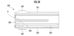
- FIG. 30 is a cross-sectional view of the third member 380 taken along a vertical plane passing through the central axis X3 of the catheter connector 300, showing the inner side of the third member 380.
- the third member 380 is a member formed in a substantially rectangular prism shape and hollow.
- the third member 380 has a lower plate portion 383, side plate portions 384 vertically provided on both ends of the lower plate portion 383, and upper plate portions 381 extending from the upper ends of the side plate portions 384 in a direction approaching each other.
- the opposing ends of the upper plate portions 381 are spaced apart, so that the third member 380 is configured to be elastically deformable about the central axis X3.
- the inner surface of the other end portion 214 side of the lower plate portion 383 is provided with a fitting recess 382 that is long in the direction of the central axis X3 and gradually deepens from the one end portion 212 side to the other end portion 214 side.
- one or more protrusions parallel to the central axis X3 are formed on the inner surfaces of both side plate portions 384, and the protrusions slide on both side surfaces of the catheter connector 300 when the third member 380 is attached.
- At least one of the side plates of the side plate portion 384 may have two or more ridges extending parallel to each other in the longitudinal direction of the side plate. This allows a plurality of ridges to abut the first member 310 and the second member 250 compared to the case of a single ridge, and therefore it is possible to prevent rattling of the first member 310 and the second member 250 when they are inserted into the third member 380.
- the ridge on the lowest surface side interferes with the locking base 257 of the second member 250, making it impossible to insert them, and thus it is possible to prevent them from being inserted upside down.
- Indicators or marks may also be provided on the upper plate portion 381 of the third member 380 and the upper surface 251 of the second member 250, respectively. This allows the user to visually confirm that the indicator is provided on the upper plate portion 381 of the third member 380, and that the indicator is provided on the upper surface 251 of the second member 250.
- an indicator or mark may be provided on the lower plate portion 381 of the third member 380 and the lower surface 231 of the first member 310.
- an indicator or mark may be provided on the right side plate portion 384 of the third member 380 and the right side surface of the first member 310 or the right side surface of the second member 250.
- an indicator or mark may be provided on the left side plate portion 384 of the third member 380 and the left side surface of the first member 310 or the left side surface of the second member 250.
- a visible print may be applied as an indicator to a portion where the first member 310 and the second member 250 do not interfere with the third member 380 when the first member 310 and the second member 250 are inserted into the third member 380.
- a visible convex portion may be provided as an indicator in a portion where the first member 310 and the second member 250 do not interfere with the third member 380 when the first member 310 and the second member 250 are inserted into the third member 380.
- a visible concave portion may be provided as an indicator in a portion where the first member 310 and the second member 250 do not interfere with the third member 380 when the first member 310 and the second member 250 are inserted into the third member 380.
- a protrusion that locally protrudes inward may be provided on portion A, which is a part of protrusion 386.
- first member 310 passes over the protrusion during the process of being inserted into first member 310 and second member 250, third member 380, a clicking sensation is felt by the user, allowing the user to recognize that first member 310 and second member 250 have been completely inserted into third member 380.
- the protrusion constitutes an operation sensation generating portion.
- the third member 380 has an end surface 389 on one end 212 side, and is open on the other end 214 side.
- the end surface 389 is cut out from the upper end to the center, and the cutout of the end surface 389 is formed as a continuous cutout from the gap formed between the two upper plate portions 381.
- the third member 380 has a protruding portion 385 formed on one end 212 side, which protrudes more than other portions around the entire outer surface of each of the plate portions.
- the protruding portion 385 formed around the entire circumference with a constant width can improve the user's grip. It is also possible to form the entire outer surface of each of the plate portions as a flat surface without providing the protruding portion 385.
- the third member 380 is attached to the first member 310 and the second member 250, which are in an engaged state, by sliding from one end 212 of the first member 310 in the N direction in FIG. 26, which is parallel to the central axis X3 direction.
- the upper plate portion 381 of the third member 380 is aligned with the upper surface of the locking base 257 of the second member 250, and one end 212 of the first member 310 is inserted from the opening on the opposite side to the end face 389.
- the third member 380 is then slid while sliding between the upper surface of the locking base 257 and the inner surface of the upper plate portion 381, the winding protrusion 246 of the catheter winding portion 244 and the inner surface of the lower plate portion 383, and the protrusions on the inner surface of the side plate portion 384 and both side surfaces of the catheter connector 300.
- the upper surface of the locking base 257 and the winding protrusion 246 are guides for easily attaching the third member 380.
- the winding protrusion 246 fits into the fitting recess 382, and the one end 212 of the first member 310 slides to a position where it abuts against the inner surface of the end face 389, completing the attachment of the third member 380.
- the second member 250 is opened, the tip of the catheter 10 is inserted into the catheter insertion section 221 until it hits the catheter, and the second member 250 is closed.
- the middle part of the catheter 10 is fitted into one of the engagement grooves 222 at the lower end of the one end 212 on the lower surface 231.
- the catheter 10 is wound around the catheter winding section 244 through one groove section 245, the winding protrusion section 246, and the other groove section 245, and is fitted into the other engagement groove 222 and pulled out.
- the third member 380 is attached so as to cover a part of the middle part of the catheter 10, and the catheter 10 is attached.
- the user can easily engage and disengage the first member 310 and the second member 250, and fix the catheter 10, with a single touch.
- the catheter connector 300 reduces differences in usage among users, improves the ability to prevent catheter kinking and dislodging, and improves usability.
- FIG. 32 is a perspective view showing the catheter connector 400 in a state in which the catheter 10 is attached
- Figure 33 is a perspective view showing the catheter connector 400 when the catheter 10 is attached or detached.
- Figure 34 is a side view of the catheter connector 400 in an engaged state.
- Figure 35 is a front view of the catheter connector 400 of Figure 34.
- the catheter connector 400 is formed in the longitudinal direction along the direction in which the catheter 10 is connected, and has a central axis X4.
- the catheter connector 400 includes a first member 410 and a second member 450.
- the tip of the catheter 10 is inserted into the catheter connector 400, and is further held by being wrapped around the upper part of the catheter connector 400.
- the catheter connector 400 is integrally formed from resin.
- the catheter connector 400 in a state in which the catheter 10 can be inserted or removed will be described.
- the first member 410 and the second member 450 are connected at their ends, and the first and second engaging portions 434 and 417, and the locking portion 463 included in the engaging portion, move relatively with the connected portion as the center of rotation.
- the engaging direction in which the first and second engaging portions 434 and 417 of the second member 450 approach the locking portion 463 of the first member 410 is the L direction
- the disengaging direction in which they move away is the M direction.
- the catheter 10 is inserted or removed in the state shown in FIG. 33, that is, in the state in which the second member 450 is rotated and opened relative to the first member 410.
- the catheter 10 can be easily inserted into and removed from the first member 410 when the second member 450 is open.
- the first member 410 is a member to which the catheter 10 and an infusion device (not shown) are connected.
- the first member 410 has one end 412, which is the end to which the catheter 10 is connected, the other end 414, which is the end opposite to the one end 412 and to which the infusion device is connected, and an intermediate portion 413 provided between the one end 412 and the other end 414.
- a cylindrical member 420 is provided by insert molding on the upper surface 411, which is the surface of the first member 410 that contacts the second member 450.
- the central axis of the cylindrical member 420 is the central axis X4 of the catheter connector 400, and the cylindrical member 420 is provided from the one end 412 to the end on the other end 414 side of the intermediate portion 413.
- the tubular member 420 has a catheter insertion section 421 at the end on one end 412 side of the tubular member 420, into which the tip of the catheter 10 is inserted.
- the catheter insertion section 421 is a generally conical hole with a large diameter at the entrance side and a gradually smaller diameter toward the inside.
- the catheter insertion section 421 is provided with its center coinciding with the central axis X4 of the catheter connector 400.
- the catheter insertion section 421 is formed so that the diameter at the entrance side is larger than the diameter at the back side, so that the tip of the catheter 10 can be easily inserted.
- first member 410 the upper surface 411 side of the first member 410 will be described.
- the end of the cylindrical member 420 on the one end 412 side is inserted and fixed into the first annular portion 415, which is provided at the one end 412 and formed in a substantially annular shape centered on the central axis X4.
- first annular portion 415 which is provided at the one end 412 and formed in a substantially annular shape centered on the central axis X4.
- both sides of the outer circumferential surface below the horizontal plane are cut in the plate thickness direction, thereby forming second engagement portions 417.
- the second engagement portions 417 are part of the planes that constitute the horizontal plane.
- the second annular portion 416 which is formed in a substantially annular shape centered on the central axis X4 and has a diameter slightly larger than that of the first annular portion 415, is provided in contact with the second engagement portion 417.
- a connection base 418 is provided on the other end 414 side of the intermediate portion 413, which is centered on the central axis X4 and has a generally annular shape with approximately the same diameter as the second annular portion 416.
- the other end 414 side of the tubular member 420 is inserted into the connection base 418, fixing the tubular member 420. Both ends of the tubular member 420 are fixed by the first annular portion 415, the second annular portion 416, and the connection base 418, and the top surface of the tubular member 420 is exposed in the remaining portions.
- the second member 450 is connected to the end of the intermediate portion 413 opposite to the one end 412.
- the other end 414 to which an infusion device is connected, is connected to the intermediate portion 413.
- the other end 414 is the portion to which the infusion device is connected and has a threaded ridge 426 to which the infusion device is connected.
- the threaded ridge 426 has a shape corresponding to the infusion device to be connected, and may be formed as a female connection portion conforming to the ISO 80369-6 standard.
- An upstream device for epidural anesthesia such as an anesthesia filter, is connected to the other end 414.
- Two threaded ridges 426 are provided at equal intervals in the circumferential direction on the circumference adjacent to the end face of the other end 414. Also, as shown in FIG. 36, the other end 414 has a connection hole 427 inside with an open end face side.
- the underside 431 side of the first member 410 will be described with reference to Figures 33 and 34.
- the tip of the one end 412 is provided with an inclined surface 419.
- the inclined surface 419 is formed facing upward and forms an angle of about 30 degrees to about 60 degrees, for example about 45 degrees, with respect to the central axis X4.
- the underside 431 side of the one end 412 is provided with a downward protrusion 432 that protrudes from the underside 431.
- the downward protrusion 432 is formed so as to gradually protrude from the underside 431 from the other end 414 side of the intermediate portion 413 of the underside 431 toward the one end 412 side.
- a downward protrusion plane 436 which is a flat surface, is formed on the underside of the downward protrusion 432.
- the tip position of the downward protrusion 432 on the one end 412 side is located slightly toward the other end 414 side from the tip position of the one end 412 on the central axis X4.
- a first engagement portion 434 is formed on the underside of the tip of the one end 412.
- An inclined surface 435 is provided at the tip of the downward protrusion 432.
- the inclined surface 419 is formed facing upward and has an angle of about 40 degrees to about 60 degrees, for example about 50 degrees, with respect to the central axis X4.
- the inclined surface 435 is provided with a forward protrusion 433 formed to protrude forward.
- the forward protrusion 433 is a part that is approximately rectangular parallelepiped shaped and is provided at the center of the inclined surface 435 in the width direction.
- An injection hole 437 is provided near the approximate center of the underside 431.
- the injection hole 437 is formed through the first member 410, and is a hole for injecting material for the tubular member 420 formed by insert molding from the underside 431. Note that in addition to the method of molding the first member 410 and then injecting material through the injection hole 437 to mold the tubular member 420, it is also possible to mold the tubular member 420 first and then insert mold the first member 410.
- the configuration of the second member 450 will be described with reference to Figures 32 and 33.
- the second member 450 is a member that presses and holds the catheter 10 via the tubular member 420 while engaged with the first member 410, and also wraps around and holds the middle portion of the catheter 10.
- the second member 450 has a connection portion 455 that is connected to the first member 410, an upper plate portion 458 that is connected to the connection portion 455, and a tip portion 459 that is connected to the upper plate portion 458.
- connection part 455 is a part that is connected to the connection base 418 of the second member 450.
- the connection part 455 is formed in a plate shape and curved. When the second member 450 engages with and disengages from the first member 410, an elastic force generated by the connection part 455 acts.
- the upper plate portion 458 is formed in a substantially flat plate shape and is connected to the connection portion 455. As shown in FIG. 34, when the second member 450 is engaged with the first member 410, the upper plate portion 458 is configured to be substantially parallel to the central axis X4.
- the upper surface 451 of the upper plate portion 458 has a pressing portion 452 located approximately in the center of the upper surface 451.
- the pressing portion 452 is formed as a slightly concave curved surface to make it easier to press the upper plate portion 458 with a finger.
- the pressing portion 452 has a plurality of linear ridges 453 to prevent the finger from slipping.
- the ridges 453 are arranged perpendicular to the central axis X4.
- a first catheter holding portion 454 is provided at the end of the upper plate portion 458 on the connection portion 455 side.
- the first catheter holding portion 454 is a plate-shaped member, and is provided so as to extend the upper surface 451 towards the other end portion 414.
- An abutment portion 465 is provided on the underside of the upper plate portion 458.
- the abutment portion 465 is a substantially rectangular parallelepiped, and is formed in a trapezoid shape with the lower side shorter than the upper side in a side view.
- the abutment portion 465 has recesses 466 formed on both side surfaces.
- the lower surface 461 of the abutment portion 465 is provided with a pressing portion 467 formed to protrude downward from the lower surface 461 in the direction of the central axis X4.
- the three pressing portions 467 are spaced apart from one another and arranged along the direction of the central axis X4. As shown in FIG. 33, each pressing portion 467 has a pressing surface 468 that is recessed in an arc shape.
- the shape of the pressing portion 467 may be a shape other than the above.
- each pressing portion 467 may be formed in a different shape.
- any two or all three of the pressing portions provided above may have the same shape.
- only one or only two of the pressing portions 467 may be provided.
- the pressing surface 468 of the pressing portion 467 may be formed as a flat surface.
- the pressing portion 467 may have two vertical surfaces and a horizontal surface formed between them, forming a space surrounded by flat surfaces on three sides and an open bottom side.
- the tip portion 459 is connected to one end 412 of the upper plate portion 458 and includes a shaped portion that curves and extends downward, from which it is bifurcated into a Y shape and has a pair of locking bases 462 extending downward.
- the locking bases 462 extend in the direction in which the second member 450 engages with the first member 410, and two locking bases 462 are formed parallel to each other.
- Each locking base 462 has a locking portion 463 at its tip.
- the locking portion 463 is formed by extending from the side surface of the other end 414 of each locking base 462 in the direction of the other end 414.
- a gap 464 is formed between each locking base 462.
- the gap 464 is a space into which the forward protrusion 433 is inserted, and the distance between the two is formed slightly larger than the width dimension of the forward protrusion 433.
- the forward protrusion 433 is inserted into the gap 464, and the locking base 462 can hold the forward protrusion 433.
- the forward protrusion 433 moves within the gap 464 while being guided by the two locking bases 462.
- the forward protrusion 433 is an engagement guide that guides the second member 450 to engage with the first member 410 at a specified position.
- Each locking base 462 has a second catheter holding portion 456.
- the second catheter holding portion 456 is attached to the surface of one end 412 of each locking base 462, parallel to each locking base 462 and with a certain gap between them, via an attachment portion.
- a protrusion 457 is provided at the tip of each second catheter holding portion 456, which prevents the catheter 10 inserted into the second catheter holding portion 456 from coming out.
- FIG. 36 is a side cross-sectional view of the catheter connector 400 in a state in which the second member 450 is engaged with the first member 410.
- An infusion device for injecting medicinal fluids and the like is connected to the connection hole 427 formed in the other end 414.
- a communication hole 429 that communicates with the connection hole 427 and has a diameter slightly smaller than the outer diameter of the catheter 10 is provided on the one end 412 side of the connection hole 427.
- the catheter 10 inserted from the catheter insertion section 421 is inserted in a state where it is aligned with the central axis of the communication hole 429 until it hits the surface of the one end 412 side of the wall portion in which the communication hole 429 is formed.
- the position of the end face of the catheter 10 on the other end 414 side in the direction of the central axis X4 is the same as the position of the end face of the tubular member 420.
- the catheter 10 can be visually confirmed through the first member 410 formed of a transparent or colored translucent material, and the tip position of the catheter 10 can be confirmed.
- the above configuration is expected to improve moldability.
- the second member 450 is released from engagement, and the tip of the catheter 10 is inserted from the catheter insertion section 421 until it hits the catheter, and the second member 450 is engaged with the first member 410.
- the middle part of the catheter 10 is hooked onto one of the locking bases 462.
- the catheter 10 is wrapped around the periphery of the second member 450, and hooked onto the first catheter holding section 454 and either of the other locking bases 462.
- the catheter 10 is then fixed with tape. In this manner, the catheter 10 is fixed to the catheter connector 400. To remove the catheter 10, the above procedure is reversed.
- the catheter connector 400 will be described with reference to Figures 34 and 38 for a permanent and temporary fixing method.
- the catheter connector 400 has a permanent fixing position for properly administering medicines and the like, and a temporary fixing position for temporarily fixing the catheter 10, with respect to the engagement position of the second member 450 that engages with the first member 410.
- Figure 34 shows the permanent fixing state
- Figure 38 shows the temporary fixing state.
- the push portion 452 is pushed with a finger in the L direction in Figure 33, i.e., downward, to engage the locking portion 463 of the first member 410 with the second member 450.
- the pushing portion 452 When the catheter connector 400 is to be fully fixed, the pushing portion 452 is pushed with a finger in the direction L in FIG. 33, and as shown in FIG. 34, the locking portion 463 of the second member 450 passes over the inclined surface 419 and reaches the first engagement portion 434, where it is caught by the first engagement portion 434. In this fixed state, the catheter connector 400 reliably maintains the engaged state and holds the catheter 10. To release the engagement, the catheter connector 400 is held in one hand and the tip portion 459 in the other hand, and the locking portion 463 is released by pulling it slightly forward along the central axis X4.
- each locking portion 463 of the first member 410 passes over the inclined surface 419, and the pushing portion 452 is pressed with a finger until it reaches the second engaging portion 417, and hooked onto the second engaging portion 417.
- each locking portion 463 is hooked onto the second engaging portion 417 provided on the side of the first annular portion 415.
- Each locking portion 463 is respectively engaged with the second engaging portion 417 on both sides of the first annular portion 415, so that the second member 450 is prevented from coming off unintentionally by the user.
- the disengagement method is the same as that for the permanent fixation, and while holding the catheter 10, the locking base 462 can be lifted from below to above to disengage the second member 450 from the first member 410.
- the degree of engagement between the first member 410 and the second member 450 is shallower than in the provisionally fixed state, and the engagement force is also weaker. Therefore, for example, in the case of a test dose, the provisionally fixed state makes it easier to disengage the catheter connector 400 compared to the provisionally fixed state.
- the locking portion 463 of the catheter connector 400 can be relatively movable and disengaged in the L direction, which is the engagement direction in which it approaches the engaging portions 463 and 417, and in the M direction, which is the disengagement direction in which it moves away from them.
- the user can easily engage and disengage the first member 410 and the second member 450, and secure the catheter 10, with a single touch.
- the catheter connector 400 reduces differences in usage among users and improves the ability to prevent kinking and dislodging of the catheter, thereby improving usability.
- the present invention provides a catheter connector that can easily and quickly connect a catheter and reliably maintain the catheter connection state.
Landscapes
- Health & Medical Sciences (AREA)
- Heart & Thoracic Surgery (AREA)
- Life Sciences & Earth Sciences (AREA)
- Hematology (AREA)
- Anesthesiology (AREA)
- Biomedical Technology (AREA)
- Engineering & Computer Science (AREA)
- Pulmonology (AREA)
- Animal Behavior & Ethology (AREA)
- General Health & Medical Sciences (AREA)
- Public Health (AREA)
- Veterinary Medicine (AREA)
- Biophysics (AREA)
- Infusion, Injection, And Reservoir Apparatuses (AREA)
Priority Applications (1)
| Application Number | Priority Date | Filing Date | Title |
|---|---|---|---|
| JP2024564446A JPWO2024128313A1 (https=) | 2022-12-16 | 2023-12-15 |
Applications Claiming Priority (4)
| Application Number | Priority Date | Filing Date | Title |
|---|---|---|---|
| JP2022201124 | 2022-12-16 | ||
| JP2022-201124 | 2022-12-16 | ||
| JP2023149557 | 2023-09-14 | ||
| JP2023-149557 | 2023-09-14 |
Publications (1)
| Publication Number | Publication Date |
|---|---|
| WO2024128313A1 true WO2024128313A1 (ja) | 2024-06-20 |
Family
ID=91485920
Family Applications (1)
| Application Number | Title | Priority Date | Filing Date |
|---|---|---|---|
| PCT/JP2023/045034 Ceased WO2024128313A1 (ja) | 2022-12-16 | 2023-12-15 | カテーテルコネクタ |
Country Status (2)
| Country | Link |
|---|---|
| JP (1) | JPWO2024128313A1 (https=) |
| WO (1) | WO2024128313A1 (https=) |
Citations (7)
| Publication number | Priority date | Publication date | Assignee | Title |
|---|---|---|---|---|
| JP2000245850A (ja) * | 1999-02-24 | 2000-09-12 | B Braun Melsungen Ag | カテーテル連結器 |
| JP2004073822A (ja) * | 2002-06-17 | 2004-03-11 | Terumo Corp | クランプとこれを用いた輸液装置 |
| JP2012520151A (ja) * | 2009-03-13 | 2012-09-06 | ツイン ベイ メディカル,インコーポレイテッド | チューブクランプ |
| JP2013005865A (ja) * | 2011-06-23 | 2013-01-10 | Top Corp | カテーテルコネクタ |
| JP2015524720A (ja) * | 2012-08-17 | 2015-08-27 | ラウメディック アーゲー | カテーテル連結器 |
| JP2018201636A (ja) * | 2017-05-31 | 2018-12-27 | 株式会社トップ | 三方活栓 |
| JP2022151743A (ja) * | 2021-03-24 | 2022-10-07 | 住友ベークライト株式会社 | 胃瘻カテーテル用の挿入治具及び胃瘻カテーテルキット |
-
2023
- 2023-12-15 JP JP2024564446A patent/JPWO2024128313A1/ja active Pending
- 2023-12-15 WO PCT/JP2023/045034 patent/WO2024128313A1/ja not_active Ceased
Patent Citations (7)
| Publication number | Priority date | Publication date | Assignee | Title |
|---|---|---|---|---|
| JP2000245850A (ja) * | 1999-02-24 | 2000-09-12 | B Braun Melsungen Ag | カテーテル連結器 |
| JP2004073822A (ja) * | 2002-06-17 | 2004-03-11 | Terumo Corp | クランプとこれを用いた輸液装置 |
| JP2012520151A (ja) * | 2009-03-13 | 2012-09-06 | ツイン ベイ メディカル,インコーポレイテッド | チューブクランプ |
| JP2013005865A (ja) * | 2011-06-23 | 2013-01-10 | Top Corp | カテーテルコネクタ |
| JP2015524720A (ja) * | 2012-08-17 | 2015-08-27 | ラウメディック アーゲー | カテーテル連結器 |
| JP2018201636A (ja) * | 2017-05-31 | 2018-12-27 | 株式会社トップ | 三方活栓 |
| JP2022151743A (ja) * | 2021-03-24 | 2022-10-07 | 住友ベークライト株式会社 | 胃瘻カテーテル用の挿入治具及び胃瘻カテーテルキット |
Also Published As
| Publication number | Publication date |
|---|---|
| JPWO2024128313A1 (https=) | 2024-06-20 |
Similar Documents
| Publication | Publication Date | Title |
|---|---|---|
| JP5962997B2 (ja) | カテーテル用アダプタ | |
| EP2399625A1 (en) | Medical needle device | |
| JP3199524B2 (ja) | ルアーニードルユニット及び注射器 | |
| CN109328087B (zh) | 连接器用帽以及带帽连接器 | |
| CN101282755B (zh) | 具有卡合特征的安全针装置及其制造方法 | |
| CN114340698A (zh) | 手掌激活型药物递送装置 | |
| US20160220766A1 (en) | Safety needle assembly | |
| JP6708625B2 (ja) | 医療用コネクタ | |
| US20100280455A1 (en) | Needle-stent device | |
| JP2021525579A (ja) | 注射デバイス用のキャップ | |
| JP7439765B2 (ja) | 雄コネクタ | |
| WO2024128313A1 (ja) | カテーテルコネクタ | |
| EP4473991A1 (en) | Needle assembly | |
| EP2087921A1 (en) | Connector | |
| JP7839488B2 (ja) | 皮下埋込型ポート | |
| JP7458140B2 (ja) | 薬液注入装置 | |
| JP6805619B2 (ja) | 留置針組立体 | |
| JP5464403B2 (ja) | 医療用ライン接続具 | |
| US20210268203A1 (en) | Medical device connectors | |
| JP7533459B2 (ja) | 留置針組立体 | |
| JP3705115B2 (ja) | 混注用輸液ライン接続具 | |
| JP7603917B2 (ja) | 留置針組立体 | |
| JP7818351B2 (ja) | 雌コネクタ | |
| JP2023051771A (ja) | 留置針 | |
| JP7383905B2 (ja) | 留置針組立体 |
Legal Events
| Date | Code | Title | Description |
|---|---|---|---|
| 121 | Ep: the epo has been informed by wipo that ep was designated in this application |
Ref document number: 23903592 Country of ref document: EP Kind code of ref document: A1 |
|
| WWE | Wipo information: entry into national phase |
Ref document number: 2024564446 Country of ref document: JP |
|
| NENP | Non-entry into the national phase |
Ref country code: DE |
|
| 122 | Ep: pct application non-entry in european phase |
Ref document number: 23903592 Country of ref document: EP Kind code of ref document: A1 |