WO2024128072A1 - 半導体装置および半導体装置の製造方法 - Google Patents
半導体装置および半導体装置の製造方法 Download PDFInfo
- Publication number
- WO2024128072A1 WO2024128072A1 PCT/JP2023/043492 JP2023043492W WO2024128072A1 WO 2024128072 A1 WO2024128072 A1 WO 2024128072A1 JP 2023043492 W JP2023043492 W JP 2023043492W WO 2024128072 A1 WO2024128072 A1 WO 2024128072A1
- Authority
- WO
- WIPO (PCT)
- Prior art keywords
- region
- concentration
- peaks
- oxygen
- carbon
- Prior art date
- Legal status (The legal status is an assumption and is not a legal conclusion. Google has not performed a legal analysis and makes no representation as to the accuracy of the status listed.)
- Ceased
Links
Images






Classifications
-
- H—ELECTRICITY
- H10—SEMICONDUCTOR DEVICES; ELECTRIC SOLID-STATE DEVICES NOT OTHERWISE PROVIDED FOR
- H10D—INORGANIC ELECTRIC SEMICONDUCTOR DEVICES
- H10D62/00—Semiconductor bodies, or regions thereof, of devices having potential barriers
- H10D62/10—Shapes, relative sizes or dispositions of the regions of the semiconductor bodies; Shapes of the semiconductor bodies
- H10D62/124—Shapes, relative sizes or dispositions of the regions of semiconductor bodies or of junctions between the regions
- H10D62/126—Top-view geometrical layouts of the regions or the junctions
- H10D62/127—Top-view geometrical layouts of the regions or the junctions of cellular field-effect devices, e.g. multicellular DMOS transistors or IGBTs
-
- H—ELECTRICITY
- H10—SEMICONDUCTOR DEVICES; ELECTRIC SOLID-STATE DEVICES NOT OTHERWISE PROVIDED FOR
- H10D—INORGANIC ELECTRIC SEMICONDUCTOR DEVICES
- H10D84/00—Integrated devices formed in or on semiconductor substrates that comprise only semiconducting layers, e.g. on Si wafers or on GaAs-on-Si wafers
- H10D84/101—Integrated devices comprising main components and built-in components, e.g. IGBT having built-in freewheel diode
- H10D84/161—IGBT having built-in components
-
- H—ELECTRICITY
- H10—SEMICONDUCTOR DEVICES; ELECTRIC SOLID-STATE DEVICES NOT OTHERWISE PROVIDED FOR
- H10D—INORGANIC ELECTRIC SEMICONDUCTOR DEVICES
- H10D12/00—Bipolar devices controlled by the field effect, e.g. insulated-gate bipolar transistors [IGBT]
- H10D12/411—Insulated-gate bipolar transistors [IGBT]
- H10D12/441—Vertical IGBTs
- H10D12/461—Vertical IGBTs having non-planar surfaces, e.g. having trenches, recesses or pillars in the surfaces of the emitter, base or collector regions
- H10D12/481—Vertical IGBTs having non-planar surfaces, e.g. having trenches, recesses or pillars in the surfaces of the emitter, base or collector regions having gate structures on slanted surfaces, on vertical surfaces, or in grooves, e.g. trench gate IGBTs
-
- H—ELECTRICITY
- H10—SEMICONDUCTOR DEVICES; ELECTRIC SOLID-STATE DEVICES NOT OTHERWISE PROVIDED FOR
- H10D—INORGANIC ELECTRIC SEMICONDUCTOR DEVICES
- H10D62/00—Semiconductor bodies, or regions thereof, of devices having potential barriers
- H10D62/50—Physical imperfections
- H10D62/53—Physical imperfections the imperfections being within the semiconductor body
-
- H—ELECTRICITY
- H10—SEMICONDUCTOR DEVICES; ELECTRIC SOLID-STATE DEVICES NOT OTHERWISE PROVIDED FOR
- H10D—INORGANIC ELECTRIC SEMICONDUCTOR DEVICES
- H10D62/00—Semiconductor bodies, or regions thereof, of devices having potential barriers
- H10D62/60—Impurity distributions or concentrations
-
- H—ELECTRICITY
- H10—SEMICONDUCTOR DEVICES; ELECTRIC SOLID-STATE DEVICES NOT OTHERWISE PROVIDED FOR
- H10D—INORGANIC ELECTRIC SEMICONDUCTOR DEVICES
- H10D64/00—Electrodes of devices having potential barriers
- H10D64/111—Field plates
- H10D64/117—Recessed field plates, e.g. trench field plates or buried field plates
-
- H—ELECTRICITY
- H10—SEMICONDUCTOR DEVICES; ELECTRIC SOLID-STATE DEVICES NOT OTHERWISE PROVIDED FOR
- H10D—INORGANIC ELECTRIC SEMICONDUCTOR DEVICES
- H10D84/00—Integrated devices formed in or on semiconductor substrates that comprise only semiconducting layers, e.g. on Si wafers or on GaAs-on-Si wafers
- H10D84/01—Manufacture or treatment
-
- H—ELECTRICITY
- H10—SEMICONDUCTOR DEVICES; ELECTRIC SOLID-STATE DEVICES NOT OTHERWISE PROVIDED FOR
- H10P—GENERIC PROCESSES OR APPARATUS FOR THE MANUFACTURE OR TREATMENT OF DEVICES COVERED BY CLASS H10
- H10P30/00—Ion implantation into wafers, substrates or parts of devices
- H10P30/20—Ion implantation into wafers, substrates or parts of devices into semiconductor materials, e.g. for doping
- H10P30/202—Ion implantation into wafers, substrates or parts of devices into semiconductor materials, e.g. for doping characterised by the semiconductor materials
- H10P30/204—Ion implantation into wafers, substrates or parts of devices into semiconductor materials, e.g. for doping characterised by the semiconductor materials into Group IV semiconductors
-
- H—ELECTRICITY
- H10—SEMICONDUCTOR DEVICES; ELECTRIC SOLID-STATE DEVICES NOT OTHERWISE PROVIDED FOR
- H10P—GENERIC PROCESSES OR APPARATUS FOR THE MANUFACTURE OR TREATMENT OF DEVICES COVERED BY CLASS H10
- H10P30/00—Ion implantation into wafers, substrates or parts of devices
- H10P30/20—Ion implantation into wafers, substrates or parts of devices into semiconductor materials, e.g. for doping
- H10P30/208—Ion implantation into wafers, substrates or parts of devices into semiconductor materials, e.g. for doping of electrically inactive species
-
- H—ELECTRICITY
- H10—SEMICONDUCTOR DEVICES; ELECTRIC SOLID-STATE DEVICES NOT OTHERWISE PROVIDED FOR
- H10D—INORGANIC ELECTRIC SEMICONDUCTOR DEVICES
- H10D12/00—Bipolar devices controlled by the field effect, e.g. insulated-gate bipolar transistors [IGBT]
- H10D12/411—Insulated-gate bipolar transistors [IGBT]
- H10D12/417—Insulated-gate bipolar transistors [IGBT] having a drift region having a doping concentration that is higher at the collector side relative to other parts of the drift region
-
- H—ELECTRICITY
- H10—SEMICONDUCTOR DEVICES; ELECTRIC SOLID-STATE DEVICES NOT OTHERWISE PROVIDED FOR
- H10D—INORGANIC ELECTRIC SEMICONDUCTOR DEVICES
- H10D12/00—Bipolar devices controlled by the field effect, e.g. insulated-gate bipolar transistors [IGBT]
- H10D12/411—Insulated-gate bipolar transistors [IGBT]
- H10D12/418—Insulated-gate bipolar transistors [IGBT] having a drift region having a doping concentration that is higher at the emitter side relative to other parts of the drift region
-
- H—ELECTRICITY
- H10—SEMICONDUCTOR DEVICES; ELECTRIC SOLID-STATE DEVICES NOT OTHERWISE PROVIDED FOR
- H10D—INORGANIC ELECTRIC SEMICONDUCTOR DEVICES
- H10D84/00—Integrated devices formed in or on semiconductor substrates that comprise only semiconducting layers, e.g. on Si wafers or on GaAs-on-Si wafers
- H10D84/80—Integrated devices formed in or on semiconductor substrates that comprise only semiconducting layers, e.g. on Si wafers or on GaAs-on-Si wafers characterised by the integration of at least one component covered by groups H10D12/00 or H10D30/00, e.g. integration of IGFETs
- H10D84/811—Combinations of field-effect devices and one or more diodes, capacitors or resistors
Definitions
- the present invention relates to a semiconductor device and a method for manufacturing a semiconductor device.
- Patent Document 1 U.S. Patent Application Publication No. 2016/0141399
- Patent Document 2 U.S. Patent Application Publication No. 2015/0076650
- Hydrogen donors are formed by implanting hydrogen ions such as protons into a semiconductor substrate.
- hydrogen ions such as protons
- the degree to which hydrogen ions become donors varies depending on the oxygen concentration or carbon concentration in the semiconductor substrate, resulting in fluctuations in the donor concentration.
- a first aspect of the present invention provides a semiconductor device including a semiconductor substrate having an upper surface and a lower surface.
- the semiconductor substrate has one or more hydrogen peaks in the depth direction, which are peaks of hydrogen chemical concentration, and the one or more hydrogen peaks may include an innermost peak that is farthest from the lower surface of the semiconductor substrate.
- the semiconductor substrate may have a lower region from the lower surface to the innermost peak, and an upper region disposed from the innermost peak to the upper surface.
- the concentration in the lower region may be at least twice the concentration in the upper region for at least one of the carbon chemical concentration and the oxygen chemical concentration.
- the semiconductor substrate may have a drift region of a first conductivity type.
- the semiconductor substrate may have a buffer region of the first conductivity type that is disposed between the lower surface and the drift region and has a doping concentration higher than that of the drift region.
- the deepest peak may be disposed in the buffer region.
- the lower region may have a flat portion in which at least one of the carbon chemical concentration and the oxygen chemical concentration is uniform.
- the lower region may have one or more carbon peaks in the depth direction, which are peaks of the carbon chemical concentration.
- the lower region may have multiple carbon peaks in the depth direction.
- the lower region may have a plurality of the hydrogen peaks in the depth direction.
- at least one of the carbon peaks may be disposed between two of the hydrogen peaks in the depth direction.
- the upper region may have one or more of the carbon peaks.
- the lower region may have one or more oxygen peaks in the depth direction, which are peaks of the oxygen chemical concentration.
- the lower region may have multiple oxygen peaks in the depth direction.
- the lower region may have a plurality of the hydrogen peaks in the depth direction.
- at least one of the oxygen peaks may be disposed between two of the hydrogen peaks in the depth direction.
- the upper region may have one or more of the oxygen peaks.
- the lower region may have, in the depth direction, one or more carbon peaks that are peaks of the carbon chemical concentration and one or more oxygen peaks that are peaks of the oxygen chemical concentration.
- At least one of the carbon peaks and at least one of the oxygen peaks may be located at the same depth position.
- the lower region may have a plurality of doping concentration peaks in the depth direction.
- the plurality of doping concentration peaks may include a plurality of first doping concentration peaks corresponding to the plurality of hydrogen peaks.
- the plurality of doping concentration peaks may include a second doping concentration peak located between two of the hydrogen peaks.
- At least one of the carbon peaks may be located at a different depth from any of the oxygen peaks.
- the carbon chemical concentration in the lower region may be 1 ⁇ 10 14 atoms/cm 3 or more.
- the oxygen chemical concentration in the lower region may be 2 ⁇ 10 17 atoms/cm 3 or more.
- a method for manufacturing a semiconductor device includes a semiconductor substrate having an upper surface and a lower surface, the semiconductor substrate having one or more hydrogen peaks in a depth direction, which are peaks of hydrogen chemical concentration, the one or more hydrogen peaks including a deepest peak furthest from the lower surface of the semiconductor substrate, and the semiconductor substrate may have a lower region from the lower surface to the deepest peak and an upper region disposed from the deepest peak to the upper surface.
- the manufacturing method may include implanting at least one of carbon, oxygen, and silicon into a region in which the lower region is to be formed. Any of the manufacturing methods may include annealing the semiconductor substrate at a temperature of 700° C. or higher. Any of the manufacturing methods may include implanting hydrogen ions into a depth position in which the one or more hydrogen peaks are to be formed.
- FIG. 1 is a top view illustrating an example of a semiconductor device 100 according to an embodiment of the present invention.
- FIG. 2 is an enlarged view of an area D in FIG.
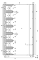
- FIG. 3 is a diagram showing an example of a cross section taken along the line ee in FIG. 2.
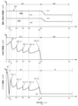
- FIG. 4 is a diagram showing an example of distribution of the doping concentration, the hydrogen chemical concentration, the oxygen chemical concentration, and the carbon chemical concentration along the line ff in FIG.
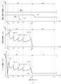
- FIG. 4 is a diagram showing another example of the distribution of the doping concentration, the hydrogen chemical concentration, the oxygen chemical concentration, and the carbon chemical concentration along the line ff in FIG. 3.
- FIG. 3 is a diagram showing an example of distribution of the doping concentration, the hydrogen chemical concentration, the oxygen chemical concentration, and the carbon chemical concentration along the line ff in FIG. 3.
- FIG. 4 is a diagram showing another example of the distribution of the doping concentration, the hydrogen chemical concentration, the oxygen chemical concentration, and the carbon chemical concentration along the line ff in FIG. 3.
- FIG. 4 is a diagram showing another example of the distribution of the doping concentration, the hydrogen chemical concentration, the oxygen chemical concentration, and the carbon chemical concentration along the line ff in FIG. 3.
- FIG. 4 is a diagram showing another example of the distribution of the doping concentration, the hydrogen chemical concentration, the oxygen chemical concentration, and the carbon chemical concentration along the line ff in FIG. 3.
- FIG. 2 is a diagram showing an example of the relative positions of an oxygen peak 232 and a carbon peak 242.
- FIG. 2 is a diagram showing another example of the relative positions of the oxygen peak 232 and the carbon peak 242.
- FIG. 4 is a diagram showing another example of the distribution of the doping concentration, the hydrogen chemical concentration, the oxygen chemical concentration, and the carbon chemical concentration along the line ff in FIG. 3.
- FIG. 4 is a diagram showing another example of the distribution of oxygen chemical concentration and carbon chemical concentration along the line ff in FIG. 3.
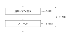
- 2A to 2C are diagrams illustrating some steps in a manufacturing method of the semiconductor device 100.
- 1A to 1C are diagrams illustrating an outline of a manufacturing method for the semiconductor device 100.
- one side in a direction parallel to the depth direction of the semiconductor substrate is referred to as "upper” and the other side as “lower.”
- the upper surface is referred to as the upper surface and the other surface is referred to as the lower surface.
- the directions of "upper” and “lower” are not limited to the direction of gravity or the directions when the semiconductor device is mounted.
- the orthogonal coordinate axes merely identify the relative positions of components, and do not limit a specific direction.
- the Z-axis does not limit the height direction relative to the ground.
- the +Z-axis direction and the -Z-axis direction are opposite directions.
- the Z-axis direction is described without indicating positive or negative, it means the direction parallel to the +Z-axis and -Z-axis.
- the orthogonal axes parallel to the top and bottom surfaces of the semiconductor substrate are referred to as the X-axis and Y-axis.
- the axis perpendicular to the top and bottom surfaces of the semiconductor substrate is referred to as the Z-axis.
- the direction of the Z-axis may be referred to as the depth direction.
- the direction parallel to the top and bottom surfaces of the semiconductor substrate, including the X-axis and Y-axis may be referred to as the horizontal direction.
- the region from the center of the semiconductor substrate in the depth direction to the top surface of the semiconductor substrate may be referred to as the top side.
- the region from the center of the semiconductor substrate in the depth direction to the bottom surface of the semiconductor substrate may be referred to as the bottom side.
- the conductivity type of a doped region doped with impurities is described as P type or N type.
- impurities may particularly mean either N type donors or P type acceptors, and may be described as dopants.
- doping means introducing donors or acceptors into a semiconductor substrate to make it a semiconductor that exhibits N type conductivity or P type conductivity.
- the doping concentration means the concentration of the donor or the concentration of the acceptor in a thermal equilibrium state.
- the net doping concentration means the net concentration obtained by adding up the donor concentration as the concentration of positive ions and the acceptor concentration as the concentration of negative ions, including the polarity of the charge.
- the donor concentration is N D and the acceptor concentration is N A
- the net doping concentration at any position is N D -N A.
- the net doping concentration may be simply referred to as the doping concentration.
- Donors have the function of supplying electrons to a semiconductor. Acceptors have the function of receiving electrons from a semiconductor. Donors and acceptors are not limited to impurities themselves.
- VOH defects in semiconductors which are formed by combining vacancies (V), oxygen (O), and hydrogen (H)
- Hydrogen donors may be donors that are formed by combining at least vacancies (V) and hydrogen (H).
- interstitial Si-H in silicon semiconductors which is formed by combining interstitial silicon (Si-i) and hydrogen
- CiOi-H in silicon semiconductors which is formed by combining interstitial carbon (Ci), interstitial oxygen (Oi), and hydrogen, also function as donors that supply electrons.
- VOH defects, CiOi-H, or interstitial Si-H may be referred to as hydrogen donors.
- the semiconductor substrate has N-type bulk donors distributed throughout.
- the bulk donors are donors due to dopants contained substantially uniformly in the ingot during the manufacture of the ingot that is the basis of the semiconductor substrate.
- the bulk donors in this example are elements other than hydrogen.
- the dopants of the bulk donors are, for example, phosphorus, antimony, arsenic, selenium, or sulfur, but are not limited thereto.
- the bulk donors in this example are phosphorus.
- the bulk donors are also contained in the P-type region.
- the semiconductor substrate may be a wafer cut from a semiconductor ingot, or may be a chip obtained by dividing the wafer.
- the semiconductor ingot may be manufactured by any of the Czochralski method (CZ method), the magnetic field application type Czochralski method (MCZ method), and the float zone method (FZ method).
- the ingot in this example is manufactured by the MCZ method.
- the oxygen concentration contained in the substrate manufactured by the MCZ method is 1 ⁇ 10 17 to 7 ⁇ 10 17 /cm 3 .
- the oxygen concentration contained in the substrate manufactured by the FZ method is 1 ⁇ 10 15 to 5 ⁇ 10 16 /cm 3. The higher the oxygen concentration, the easier it is to generate hydrogen donors.
- the bulk donor concentration may be the chemical concentration of the bulk donors distributed throughout the semiconductor substrate, and may be between 90% and 100% of the chemical concentration.
- the semiconductor substrate may be a non-doped substrate that does not contain a dopant such as phosphorus.
- the bulk donor concentration (D0) of the non-doped substrate is, for example, 1 ⁇ 10 10 /cm 3 or more and 5 ⁇ 10 12 /cm 3 or less.
- the bulk donor concentration (D0) of the non-doped substrate is preferably 1 ⁇ 10 11 /cm 3 or more.
- the bulk donor concentration (D0) of the non-doped substrate is preferably 5 ⁇ 10 12 /cm 3 or less.
- each concentration may be a value at room temperature.
- a value at 300 K (Kelvin) (approximately 26.9° C.) may be used.
- chemical concentration refers to the atomic density of an impurity measured regardless of the state of electrical activation.
- the chemical concentration can be measured, for example, by secondary ion mass spectrometry (SIMS).
- the above-mentioned net doping concentration can be measured by a voltage-capacitance measurement method (CV method).
- the carrier concentration measured by a spreading resistance measurement method (SR method) may be the net doping concentration.
- the carrier concentration measured by the CV method or the SR method may be a value in a thermal equilibrium state.
- the donor concentration is sufficiently larger than the acceptor concentration in an N-type region, the carrier concentration in that region may be the donor concentration.
- the carrier concentration in that region may be the acceptor concentration.
- the doping concentration in an N-type region may be referred to as the donor concentration
- the doping concentration in a P-type region may be referred to as the acceptor concentration.
- the peak value may be taken as the concentration of the donor, acceptor or net doping in the region.
- the concentration of the donor, acceptor or net doping is almost uniform, the average value of the concentration of the donor, acceptor or net doping in the region may be taken as the concentration of the donor, acceptor or net doping.
- atoms/cm 3 or /cm 3 is used to express concentration per unit volume. This unit is used for donor or acceptor concentration or chemical concentration in a semiconductor substrate. The notation of atoms may be omitted.
- the carrier concentration measured by the SR method may be lower than the donor or acceptor concentration.
- the carrier mobility of the semiconductor substrate may be lower than the value in the crystalline state. The reduction in carrier mobility occurs when the carriers are scattered due to disorder in the crystal structure caused by lattice defects, etc.
- the donor or acceptor concentration calculated from the carrier concentration measured by the CV method or the SR method may be lower than the chemical concentration of the element representing the donor or acceptor.
- the donor concentration of phosphorus or arsenic, which acts as a donor in a silicon semiconductor, or the acceptor concentration of boron, which acts as an acceptor is about 99% of the chemical concentration.
- the donor concentration of hydrogen, which acts as a donor in a silicon semiconductor is about 0.1% to 10% of the chemical concentration of hydrogen.
- FIG. 1 is a top view showing an example of a semiconductor device 100 according to one embodiment of the present invention.
- FIG. 1 the positions of each component projected onto the top surface of a semiconductor substrate 10 are shown.
- FIG. 1 only some of the components of the semiconductor device 100 are shown, and some components are omitted.
- the semiconductor device 100 includes a semiconductor substrate 10.
- the semiconductor substrate 10 is a substrate formed of a semiconductor material.
- the semiconductor substrate 10 is a silicon substrate.
- the semiconductor substrate 10 has edges 162 when viewed from above. When simply referred to as a top view in this specification, it means that the semiconductor substrate 10 is viewed from the top side.
- the semiconductor substrate 10 has two sets of edges 162 that face each other when viewed from above. In FIG. 1, the X-axis and Y-axis are parallel to one of the edges 162. The Z-axis is perpendicular to the top surface of the semiconductor substrate 10.
- the semiconductor substrate 10 has an active portion 160.
- the active portion 160 is a region through which a main current flows in the depth direction between the upper and lower surfaces of the semiconductor substrate 10 when the semiconductor device 100 is in operation.
- An emitter electrode is provided above the active portion 160, but is omitted in FIG. 1.
- the active portion 160 may refer to the region that overlaps with the emitter electrode when viewed from above.
- the active portion 160 may also include the region sandwiched between the active portions 160 when viewed from above.
- the active section 160 is provided with at least one of a transistor section 70 including a transistor element such as an IGBT (Insulated Gate Bipolar Transistor) and a diode section 80 including a diode element such as a free wheel diode (FWD).
- IGBT Insulated Gate Bipolar Transistor
- FWD free wheel diode
- the transistor sections 70 and the diode sections 80 are alternately arranged along a predetermined arrangement direction (the X-axis direction in this example) on the upper surface of the semiconductor substrate 10.
- the semiconductor device 100 in this example is a reverse conducting IGBT (RC-IGBT).
- the region in which the transistor section 70 is arranged is marked with the symbol "I”
- the region in which the diode section 80 is arranged is marked with the symbol "F”.
- the direction perpendicular to the arrangement direction in a top view may be referred to as the extension direction (the Y-axis direction in FIG. 1).
- the transistor section 70 and the diode section 80 may each have a longitudinal direction in the extension direction.
- the length of the transistor section 70 in the Y-axis direction is greater than its width in the X-axis direction.
- the length of the diode section 80 in the Y-axis direction is greater than its width in the X-axis direction.
- the extension direction of the transistor section 70 and the diode section 80 may be the same as the longitudinal direction of each trench section described later.
- the diode section 80 has an N+ type cathode region in a region that contacts the lower surface of the semiconductor substrate 10.
- the region in which the cathode region is provided is referred to as the diode section 80.
- the diode section 80 is a region that overlaps with the cathode region when viewed from above.
- a P+ type collector region may be provided in a region other than the cathode region on the lower surface of the semiconductor substrate 10.
- an extension region 81 that extends the diode section 80 in the Y-axis direction to the gate wiring described below may also be included in the diode section 80.
- a collector region is provided on the lower surface of the extension region 81.
- the transistor section 70 has a P+ type collector region in a region that contacts the bottom surface of the semiconductor substrate 10.
- the transistor section 70 has a gate structure that has an N type emitter region, a P type base region, a gate conductive portion, and a gate insulating film periodically arranged on the top surface side of the semiconductor substrate 10.
- the semiconductor device 100 may have one or more pads above the semiconductor substrate 10.
- the semiconductor device 100 in this example has a gate pad 164.
- the semiconductor device 100 may also have pads such as an anode pad, a cathode pad, and a current detection pad.
- Each pad is disposed near an edge 162.
- the vicinity of the edge 162 refers to the area between the edge 162 and the emitter electrode in a top view.
- each pad may be connected to an external circuit via wiring such as a wire.
- a gate potential is applied to the gate pad 164.
- the gate pad 164 is electrically connected to the conductive portion of the gate trench portion of the active portion 160.
- the semiconductor device 100 includes a gate wiring that connects the gate pad 164 and the gate trench portion. In FIG. 1, the gate wiring is hatched with diagonal lines.
- the gate wiring in this example has a peripheral gate wiring 130 and an active side gate wiring 131.
- the peripheral gate wiring 130 is disposed between the active portion 160 and an edge 162 of the semiconductor substrate 10 in a top view.
- the peripheral gate wiring 130 in this example surrounds the active portion 160 in a top view.
- the region surrounded by the peripheral gate wiring 130 in a top view may be the active portion 160.
- a well region is formed below the gate wiring.
- the well region is a P-type region with a higher concentration than the base region described below, and is formed from the top surface of the semiconductor substrate 10 to a position deeper than the base region.
- the region surrounded by the well region in a top view may be the active portion 160.
- the peripheral gate wiring 130 is connected to the gate pad 164.
- the peripheral gate wiring 130 is disposed above the semiconductor substrate 10.
- the peripheral gate wiring 130 may be a metal wiring containing aluminum or the like.
- the active side gate wiring 131 is provided in the active section 160. By providing the active side gate wiring 131 in the active section 160, the variation in wiring length from the gate pad 164 can be reduced for each region of the semiconductor substrate 10.
- the peripheral gate wiring 130 and the active side gate wiring 131 are connected to the gate trench portion of the active portion 160.
- the peripheral gate wiring 130 and the active side gate wiring 131 are disposed above the semiconductor substrate 10.
- the peripheral gate wiring 130 and the active side gate wiring 131 may be wiring formed of a semiconductor such as polysilicon doped with impurities.
- the active side gate wiring 131 may be connected to the peripheral gate wiring 130.
- the active side gate wiring 131 is provided extending in the X-axis direction from one peripheral gate wiring 130 to the other peripheral gate wiring 130 sandwiching the active section 160, so as to cross the active section 160 at approximately the center in the Y-axis direction.
- the transistor section 70 and the diode section 80 may be arranged alternately in the X-axis direction in each divided region.
- the semiconductor device 100 may also include a temperature sensor (not shown) that is a PN junction diode formed of polysilicon or the like, and a current detector (not shown) that simulates the operation of a transistor section provided in the active section 160.
- a temperature sensor not shown
- a current detector not shown
- the semiconductor device 100 includes an edge termination structure 90 between the active portion 160 and the edge 162 when viewed from above.
- the edge termination structure 90 in this example is disposed between the peripheral gate wiring 130 and the edge 162.
- the edge termination structure 90 reduces electric field concentration on the upper surface side of the semiconductor substrate 10.
- the edge termination structure 90 may include at least one of a guard ring, a field plate, and a resurf that are arranged in a ring shape surrounding the active portion 160.
- Region D includes transistor section 70, diode section 80, and active side gate wiring 131.
- the semiconductor device 100 of this example includes a gate trench section 40, a dummy trench section 30, a well region 11, an emitter region 12, a base region 14, and a contact region 15 provided inside the upper surface side of the semiconductor substrate 10.
- the gate trench section 40 and the dummy trench section 30 are each an example of a trench section.
- the semiconductor device 100 of this example also includes an emitter electrode 52 and an active side gate wiring 131 provided above the upper surface of the semiconductor substrate 10.
- the emitter electrode 52 and the active side gate wiring 131 are provided separately from each other.
- An interlayer insulating film is provided between the emitter electrode 52 and the active gate wiring 131 and the upper surface of the semiconductor substrate 10, but is omitted in FIG. 2.
- contact holes 54 are provided in the interlayer insulating film, penetrating the interlayer insulating film. In FIG. 2, each contact hole 54 is hatched with diagonal lines.
- the emitter electrode 52 is provided above the gate trench portion 40, the dummy trench portion 30, the well region 11, the emitter region 12, the base region 14, and the contact region 15.
- the emitter electrode 52 contacts the emitter region 12, the contact region 15, and the base region 14 on the upper surface of the semiconductor substrate 10 through a contact hole 54.
- the emitter electrode 52 is also connected to the dummy conductive portion in the dummy trench portion 30 through a contact hole provided in the interlayer insulating film.
- the emitter electrode 52 may be connected to the dummy conductive portion of the dummy trench portion 30 at the tip of the dummy trench portion 30 in the Y-axis direction.
- the dummy conductive portion of the dummy trench portion 30 does not need to be connected to the emitter electrode 52 and the gate conductive portion, and may be controlled to a potential different from the potential of the emitter electrode 52 and the potential of the gate conductive portion.
- the active side gate wiring 131 is connected to the gate trench portion 40 through a contact hole provided in the interlayer insulating film.
- the active side gate wiring 131 may be connected to the gate conductive portion of the gate trench portion 40 at the tip portion 41 of the gate trench portion 40 in the Y-axis direction.
- the active side gate wiring 131 is not connected to the dummy conductive portion in the dummy trench portion 30.
- the emitter electrode 52 is formed of a material containing metal.
- FIG. 2 shows the range in which the emitter electrode 52 is provided.
- the emitter electrode 52 is formed of aluminum or an aluminum-silicon alloy, such as a metal alloy such as AlSi or AlSiCu.
- the emitter electrode 52 may have a barrier metal formed of titanium or a titanium compound under the region formed of aluminum or the like.
- the emitter electrode 52 may have a plug formed by embedding tungsten or the like in the contact hole so as to contact the barrier metal and aluminum or the like.
- the well region 11 is provided so as to overlap with the active side gate wiring 131.
- the well region 11 is also provided so as to extend by a predetermined width into an area where it does not overlap with the active side gate wiring 131.
- the well region 11 is provided away from the end of the contact hole 54 in the Y-axis direction toward the active side gate wiring 131.
- the well region 11 is a region of a second conductivity type having a higher doping concentration than the base region 14.
- the base region 14 is P- type
- the well region 11 is P+ type.
- the transistor section 70 and the diode section 80 each have multiple trench sections arranged in the arrangement direction.
- one or more gate trench sections 40 and one or more dummy trench sections 30 are alternately provided along the arrangement direction.
- the diode section 80 of this example multiple dummy trench sections 30 are provided along the arrangement direction.
- no gate trench sections 40 are provided.
- the gate trench portion 40 in this example may have two straight portions 39 (portions of the trench that are straight along the extension direction) that extend along an extension direction perpendicular to the arrangement direction, and a tip portion 41 that connects the two straight portions 39.
- the extension direction in FIG. 2 is the Y-axis direction.
- the tip 41 is curved when viewed from above.
- the tip 41 connects the ends of the two straight portions 39 in the Y-axis direction, thereby reducing electric field concentration at the ends of the straight portions 39.
- the dummy trench portion 30 is provided between each straight portion 39 of the gate trench portion 40.
- One dummy trench portion 30 may be provided between each straight portion 39, or multiple dummy trench portions 30 may be provided.
- the dummy trench portion 30 may have a straight line shape extending in the extension direction, and may have a straight line portion 29 and a tip portion 31, similar to the gate trench portion 40.
- the semiconductor device 100 shown in FIG. 2 includes both a straight line dummy trench portion 30 without a tip portion 31 and a dummy trench portion 30 with a tip portion 31.
- the diffusion depth of the well region 11 may be deeper than the depth of the gate trench portion 40 and the dummy trench portion 30.
- the ends in the Y-axis direction of the gate trench portion 40 and the dummy trench portion 30 are provided in the well region 11 when viewed from above. In other words, at the ends in the Y-axis direction of each trench portion, the bottoms in the depth direction of each trench portion are covered by the well region 11. This makes it possible to reduce electric field concentration at the bottoms of each trench portion.
- the mesa portion refers to the region inside the semiconductor substrate 10 that is sandwiched between the trench portions.
- the upper end of the mesa portion is the upper surface of the semiconductor substrate 10.
- the depth position of the lower end of the mesa portion is the same as the depth position of the lower end of the trench portion.
- the mesa portion is provided on the upper surface of the semiconductor substrate 10, extending in the extension direction (Y-axis direction) along the trench.
- the transistor portion 70 is provided with a mesa portion 60
- the diode portion 80 is provided with a mesa portion 61.
- the term "mesa portion” refers to both the mesa portion 60 and the mesa portion 61.
- a base region 14 is provided in each mesa portion. Of the base regions 14 exposed on the upper surface of the semiconductor substrate 10 in the mesa portion, the region closest to the active side gate wiring 131 is referred to as the base region 14-e. In FIG. 2, the base region 14-e is shown at one end in the extension direction of each mesa portion, but a base region 14-e is also provided at the other end of each mesa portion.
- at least one of a first conductive type emitter region 12 and a second conductive type contact region 15 may be provided in a region sandwiched between the base regions 14-e in a top view.
- the emitter region 12 is N+ type
- the contact region 15 is P+ type.
- the emitter region 12 and the contact region 15 may be provided between the base region 14 and the upper surface of the semiconductor substrate 10 in the depth direction.
- the mesa portion 60 of the transistor portion 70 has an emitter region 12 exposed on the upper surface of the semiconductor substrate 10.
- the emitter region 12 is provided in contact with the gate trench portion 40.
- the mesa portion 60 in contact with the gate trench portion 40 may have a contact region 15 exposed on the upper surface of the semiconductor substrate 10.
- the contact regions 15 and emitter regions 12 in the mesa portion 60 are each provided from one trench portion to the other trench portion in the X-axis direction. As an example, the contact regions 15 and emitter regions 12 in the mesa portion 60 are alternately arranged along the extension direction of the trench portion (Y-axis direction).
- the contact region 15 and emitter region 12 of the mesa portion 60 may be provided in a stripe shape along the extension direction (Y-axis direction) of the trench portion.
- the emitter region 12 is provided in a region that contacts the trench portion, and the contact region 15 is provided in a region sandwiched between the emitter regions 12.
- the mesa portion 61 of the diode section 80 does not have an emitter region 12.
- a base region 14 and a contact region 15 may be provided on the upper surface of the mesa portion 61.
- a contact region 15 may be provided in contact with each of the base regions 14-e.
- a base region 14 may be provided in the region sandwiched between the contact regions 15 on the upper surface of the mesa portion 61.
- the base region 14 may be disposed in the entire region sandwiched between the contact regions 15.
- a contact hole 54 is provided above each mesa portion.
- the contact hole 54 is located in a region sandwiched between the base regions 14-e.
- the contact holes 54 are provided above the contact region 15, the base region 14, and the emitter region 12.
- the contact holes 54 are not provided in the regions corresponding to the base region 14-e and the well region 11.
- the contact holes 54 may be located in the center of the arrangement direction (X-axis direction) of the mesa portions 60.
- an N+ type cathode region 82 is provided in a region adjacent to the underside of the semiconductor substrate 10.
- a P+ type collector region 22 may be provided in the region of the underside of the semiconductor substrate 10 where the cathode region 82 is not provided.
- the cathode region 82 and the collector region 22 are provided between the underside 23 of the semiconductor substrate 10 and the buffer region 20.
- the boundary between the cathode region 82 and the collector region 22 is indicated by a dotted line.
- the cathode region 82 is disposed away from the well region 11 in the Y-axis direction. This ensures a distance between the cathode region 82 and the P-type region (well region 11), which has a relatively high doping concentration and is formed deep, and improves the breakdown voltage.
- the end of the cathode region 82 in the Y-axis direction is disposed farther from the well region 11 than the end of the contact hole 54 in the Y-axis direction.
- the end of the cathode region 82 in the Y-axis direction may be disposed between the well region 11 and the contact hole 54.
- FIG. 3 is a diagram showing an example of the e-e cross section in FIG. 2.
- the e-e cross section is an XZ plane passing through the emitter region 12 and the cathode region 82.
- the semiconductor device 100 of this example has a semiconductor substrate 10, an interlayer insulating film 38, an emitter electrode 52, and a collector electrode 24.
- the interlayer insulating film 38 is provided on the upper surface of the semiconductor substrate 10.
- the interlayer insulating film 38 is a film that includes at least one layer of an insulating film such as silicate glass doped with impurities such as boron or phosphorus, a thermal oxide film, and other insulating films.
- the interlayer insulating film 38 is provided with the contact hole 54 described in FIG. 2.
- the emitter electrode 52 is provided above the interlayer insulating film 38.
- the emitter electrode 52 is in contact with the upper surface 21 of the semiconductor substrate 10 through a contact hole 54 in the interlayer insulating film 38.
- the collector electrode 24 is provided on the lower surface 23 of the semiconductor substrate 10.
- the emitter electrode 52 and the collector electrode 24 are made of a metal material such as aluminum.
- the direction connecting the emitter electrode 52 and the collector electrode 24 (the Z-axis direction) is referred to as the depth direction.
- the semiconductor substrate 10 has an N-type or N-type drift region 18.
- the drift region 18 is provided in each of the transistor portion 70 and the diode portion 80.
- an N+ type emitter region 12 and a P- type base region 14 are provided in this order from the upper surface 21 side of the semiconductor substrate 10.
- a drift region 18 is provided below the base region 14.
- An N+ type accumulation region 16 may be provided in the mesa portion 60. The accumulation region 16 is disposed between the base region 14 and the drift region 18.
- the emitter region 12 is exposed on the upper surface 21 of the semiconductor substrate 10 and is provided in contact with the gate trench portion 40.
- the emitter region 12 may be in contact with the trench portions on both sides of the mesa portion 60.
- the emitter region 12 has a higher doping concentration than the drift region 18.
- the base region 14 is provided below the emitter region 12. In this example, the base region 14 is provided in contact with the emitter region 12. The base region 14 may be in contact with the trench portions on both sides of the mesa portion 60.
- the accumulation region 16 is provided below the base region 14.
- the accumulation region 16 is an N+ type region with a higher doping concentration than the drift region 18. In other words, the accumulation region 16 has a higher donor concentration than the drift region 18.
- the carrier injection enhancement effect IE effect
- the accumulation region 16 may be provided so as to cover the entire lower surface of the base region 14 in each mesa portion 60.
- the mesa portion 61 of the diode section 80 has a P-type base region 14 in contact with the upper surface 21 of the semiconductor substrate 10.
- a drift region 18 is provided below the base region 14.
- an accumulation region 16 may be provided below the base region 14.
- an N+ type buffer region 20 may be provided below the drift region 18.
- the doping concentration of the buffer region 20 is higher than the doping concentration of the drift region 18.
- the buffer region 20 may have a concentration peak with a higher doping concentration than the drift region 18.
- the doping concentration of the concentration peak refers to the doping concentration at the apex of the concentration peak.
- the doping concentration of the drift region 18 may be the average value of the doping concentration in a region where the doping concentration distribution is approximately flat.
- the buffer region 20 may have two or more concentration peaks in the depth direction (Z-axis direction) of the semiconductor substrate 10.
- the concentration peak of the buffer region 20 may be located at the same depth as the chemical concentration peak of hydrogen (protons) or phosphorus, for example.
- the buffer region 20 may function as a field stop layer that prevents the depletion layer spreading from the lower end of the base region 14 from reaching the P+ type collector region 22 and the N+ type cathode region 82.
- a P+ type collector region 22 is provided below the buffer region 20.
- the acceptor concentration of the collector region 22 is higher than the acceptor concentration of the base region 14.
- the collector region 22 may contain the same acceptor as the base region 14, or may contain a different acceptor.
- the acceptor of the collector region 22 is, for example, boron.
- an N+ type cathode region 82 is provided below the buffer region 20.
- the donor concentration of the cathode region 82 is higher than the donor concentration of the drift region 18.
- the donor of the cathode region 82 is, for example, hydrogen or phosphorus.
- the elements that serve as the donor and acceptor of each region are not limited to the above-mentioned examples.
- the collector region 22 and the cathode region 82 are exposed to the lower surface 23 of the semiconductor substrate 10 and are connected to the collector electrode 24.
- the collector electrode 24 may be in contact with the entire lower surface 23 of the semiconductor substrate 10.
- the emitter electrode 52 and the collector electrode 24 are formed of a metal material such as aluminum.
- each trench portion is provided from the upper surface 21 of the semiconductor substrate 10, penetrating the base region 14, to below the base region 14. In regions where at least one of the emitter region 12, the contact region 15, and the accumulation region 16 is provided, each trench portion also penetrates these doped regions.
- the trench portion penetrating the doped region is not limited to being manufactured in the order of forming the doped region and then the trench portion.
- the trench portion penetrating the doped region also includes a trench portion formed after the trench portion is formed.
- the transistor section 70 has a gate trench section 40 and a dummy trench section 30.
- the diode section 80 has a dummy trench section 30, but does not have a gate trench section 40.
- the boundary between the diode section 80 and the transistor section 70 in the X-axis direction is the boundary between the cathode region 82 and the collector region 22.
- the gate trench portion 40 has a gate trench provided on the upper surface 21 of the semiconductor substrate 10, a gate insulating film 42, and a gate conductive portion 44.
- the gate insulating film 42 is provided to cover the inner wall of the gate trench.
- the gate insulating film 42 may be formed by oxidizing or nitriding the semiconductor on the inner wall of the gate trench.
- the gate conductive portion 44 is provided inside the gate insulating film 42 inside the gate trench. In other words, the gate insulating film 42 insulates the gate conductive portion 44 from the semiconductor substrate 10.
- the gate conductive portion 44 is formed of a conductive material such as polysilicon.
- the gate conductive portion 44 may be provided longer than the base region 14 in the depth direction.
- the gate trench portion 40 in this cross section is covered by the interlayer insulating film 38 on the upper surface 21 of the semiconductor substrate 10.
- the gate conductive portion 44 is electrically connected to the gate wiring. When a predetermined gate voltage is applied to the gate conductive portion 44, a channel is formed by an electron inversion layer in the surface layer of the interface of the base region 14 that contacts the gate trench portion 40.
- the dummy trench portion 30 may have the same structure as the gate trench portion 40 in the cross section.
- the dummy trench portion 30 has a dummy trench, a dummy insulating film 32, and a dummy conductive portion 34 provided on the upper surface 21 of the semiconductor substrate 10.
- the dummy conductive portion 34 is electrically connected to the emitter electrode 52.
- the dummy insulating film 32 is provided to cover the inner wall of the dummy trench.
- the dummy conductive portion 34 is provided inside the dummy trench and is provided on the inside of the dummy insulating film 32.
- the dummy insulating film 32 insulates the dummy conductive portion 34 from the semiconductor substrate 10.
- the dummy conductive portion 34 may be formed of the same material as the gate conductive portion 44.
- the dummy conductive portion 34 is formed of a conductive material such as polysilicon.
- the dummy conductive portion 34 may have the same length in the depth direction as the gate conductive portion 44.
- the gate trench portion 40 and the dummy trench portion 30 are covered by an interlayer insulating film 38 on the upper surface 21 of the semiconductor substrate 10.
- the bottoms of the dummy trench portion 30 and the gate trench portion 40 may be curved and convex downward (curved in cross section).
- FIG. 4 is a diagram showing an example of the distribution of the doping concentration, hydrogen chemical concentration, oxygen chemical concentration, and carbon chemical concentration along the line f-f in FIG. 3.
- the doping concentration may be a carrier concentration measured by the SR method or the like.
- the chemical concentrations of hydrogen, oxygen, and carbon may be measured by the SIMS method or the like.
- the line f-f is a line that is parallel to the Z axis and passes through a part of the buffer region 20 and the drift region 18.
- the horizontal axis in FIG. 4 indicates the depth position (position in the Z axis direction) in the semiconductor substrate 10.
- the lower surface 23 of the semiconductor substrate 10 is set as the reference position (0) in the Z axis direction, and the distance from the lower surface 23 is set as the position in the Z axis direction.
- a drift region 18 is provided above the buffer region 20.
- the drift region 18 may have a substantially constant doping concentration.
- the doping concentration of the drift region 18 may be equal to the bulk donor concentration BD or may be higher than the bulk donor concentration BD. In this example, the doping concentration of the drift region 18 is equal to the bulk donor concentration BD.
- the bulk donor concentration BD may be the minimum value of the bulk donor chemical concentration in the semiconductor substrate 10, the bulk donor chemical concentration at the center position in the depth direction of the semiconductor substrate 10, or the average value of the bulk donor chemical concentration in the drift region 18.
- the bulk donor is a dopant other than oxygen and carbon, and is distributed throughout the semiconductor substrate 10.
- the bulk donor is, for example, phosphorus, but may also be arsenic or antimony, and is not limited to these.
- the bulk donor concentration BD is the net concentration determined by the difference between the bulk donor concentration and the bulk acceptor concentration.
- the bulk donor and bulk acceptor concentrations may be values measured by the SIMS method or the like.
- the depth position of the boundary between the drift region 18 and the buffer region 20 is Zb.
- the depth position Zb is the depth position where the doping concentration first becomes the bulk donor concentration BD in the direction from the buffer region 20 toward the drift region 18.
- the buffer region 20 is provided between the drift region 18 and the bottom surface 23.
- the collector region 22 is provided between the buffer region 20 and the bottom surface 23.
- the boundary position Z0 between the collector region 22 and the buffer region 20 is the position of the PN junction between the collector region 22 and the buffer region 20.
- the buffer region 20 in this example is a region that contains hydrogen donors.
- the buffer region 20 is defined as an N-type region between the drift region 18 and the collector region 22 where hydrogen atoms are present (e.g., the hydrogen chemical concentration is greater than the lower detection limit) and where the doping concentration is higher than the bulk donor concentration BD.
- the buffer region 20 has one or more doping concentration peaks 211 in the depth direction.
- doping concentration peak 211-1, doping concentration peak 211-2, doping concentration peak 211-3, doping concentration peak 211-4, and doping concentration peak 211-5 are arranged in the buffer region 20.
- the doping concentration peak 211-1 closest to the bottom surface 23 may be referred to as the shallowest doping concentration peak
- the doping concentration peak 211-5 farthest from the bottom surface 23 may be referred to as the deepest doping concentration peak.
- the buffer region 20 has one or more hydrogen peaks 221 in the depth direction.
- the hydrogen peaks 221 are hydrogen chemical concentration peaks.
- hydrogen peaks 221-1, 221-2, 221-3, 221-4, and 221-5 are arranged in the buffer region 20 in order from the peak closest to the lower surface 23 of the semiconductor substrate 10.
- the hydrogen peak 221-1 closest to the lower surface 23 may be referred to as the shallowest peak
- the hydrogen peak 221-5 farthest from the lower surface 23 may be referred to as the deepest peak.
- the doping concentration peak 211-1 closest to the lower surface 23 of the semiconductor substrate 10 may have a dopant of phosphorus. In this case, the peak 211-1 becomes the phosphorus peak 211-1.
- the depth position of the apex of hydrogen peak 221-m (m is an integer of 1 or greater) is Zm.
- the position of the apex of a peak may be referred to as the peak position.
- the concentration at the apex of a peak may be referred to as the peak concentration.
- Doping concentration peak 211-m may be located at the same depth position Zm as hydrogen peak 221-m.
- the depth position of the apex of one of the two peaks is included within the full width at half maximum in the depth direction of the other peak, the two peaks may be considered to be located at the same depth position.
- the semiconductor substrate 10 has a lower region 201 and an upper region 202.
- the lower region 201 is a region from the lower surface 23 to the deepest peak (hydrogen peak 221-5 in this example).
- the depth position of the upper end of the lower region 201 may be the depth position Z5 of the apex of the hydrogen peak 221-5, or may be a depth position (Zb in the example of FIG. 4) where the hydrogen chemical concentration is below the lower detection limit on the upper surface 21 side from the apex of the hydrogen peak 221-5, or may be the depth position Zb of the boundary between the buffer region 20 and the drift region 18.
- the upper end position of the lower region 201 is Zb.
- the lower region 201 includes the buffer region 20, but in other examples, the lower region 201 may be a region different from the buffer region 20. In this case, the lower region 201 also includes one or more hydrogen peaks 221.
- the upper region 202 is a region located from the deepest peak (in this example, hydrogen peak 221-5) to the upper surface 21.
- the upper region 202 is located closer to the upper surface 21 than the lower region 201.
- the depth position of the lower end of the upper region 202 may be the same as or different from the depth position of the upper end of the lower region 201.
- the depth position of the lower end of the upper region 202 in this example is Zb, which is the same as the depth position Zb of the upper end of the lower region 201.
- the upper region 202 may be the entire region from depth position Zb to the upper surface 21, or it may be a portion of the region.
- the upper region 202 in this example is a portion of the region from depth position Zb to the upper surface 21.
- the upper end position Zu of the upper region 202 may be located in the drift region 18.
- the depth length of the upper region 202 (Zu-Zb in this example) may be the same as, smaller than, or larger than the depth length of the
- the carbon chemical concentration in the lower region 201 is Ca1, and the oxygen chemical concentration is Ox1.
- the carbon chemical concentration in the upper region 202 is Ca2, and the oxygen chemical concentration is Ox2.
- the average values of the carbon chemical concentration and the oxygen chemical concentration in the lower region 201 may be used, or the maximum values may be used.
- the average values of the carbon chemical concentration and the oxygen chemical concentration in the upper region 202 may be used, or the maximum values may be used.
- the concentration in the lower region 201 is at least twice the concentration in the upper region 202.
- the carbon chemical concentration Ca1 in the lower region 201 is at least twice the carbon chemical concentration Ca2 in the upper region 202
- the oxygen chemical concentration OX1 in the lower region 201 is at least twice the oxygen chemical concentration Ox2 in the upper region 202.
- the carbon chemical concentration Ca1 may be 1 ⁇ 10 14 atoms/cm 3 or more.
- the carbon chemical concentration Ca1 may be 5 ⁇ 10 14 atoms/cm 3 or more, 1 ⁇ 10 15 atoms/cm 3 or more, 5 ⁇ 10 15 atoms/cm 3 or more, or 1 ⁇ 10 16 atoms/cm 3 or more.
- the oxygen chemical concentration Ox1 may be 2 ⁇ 10 17 atoms/cm 3 or more.
- the oxygen chemical concentration Ox1 may be 3 ⁇ 10 17 atoms/cm 3 or more, or 5 ⁇ 10 17 atoms/cm 3 or more.
- Carbon and oxygen are distributed almost uniformly in a semiconductor substrate 10 (semiconductor wafer) cut from a semiconductor ingot.
- the carbon chemical concentration and oxygen chemical concentration vary between substrates.
- Hydrogen ions may be implanted into the semiconductor substrate 10 to form hydrogen donors, forming a high-concentration region such as the buffer region 20.
- the degree to which hydrogen donors are formed for a given dose of hydrogen ions varies depending on the carbon chemical concentration and oxygen chemical concentration of the semiconductor substrate 10.
- the degree to which VOH defects are formed varies depending on the oxygen chemical concentration
- the degree to which CiOi-H is formed varies depending on the oxygen chemical concentration and carbon chemical concentration.
- the doping concentration of a high-concentration region such as the buffer region 20 varies depending on the carbon chemical concentration and oxygen chemical concentration of the semiconductor substrate 10.
- At least one of carbon and oxygen is selectively injected into the lower region 201 of the semiconductor substrate 10 to adjust at least one of the carbon chemical concentration and the oxygen chemical concentration in the lower region 201. This reduces the effects of variations in the carbon chemical concentration and oxygen chemical concentration of the semiconductor substrate 10, and allows for precise control of the doping concentration in the lower region 201 (buffer region 20 in this example).
- the concentration in the lower region 201 may be 5 times or more, or may be 10 times or more, higher than the concentration in the upper region 202.
- the dose of carbon and oxygen implanted into the lower region 201 can be controlled with relatively high precision. Therefore, by implanting a large amount of carbon or oxygen into the lower region 201, the proportion of the variation in the carbon chemical concentration and the oxygen chemical concentration in the semiconductor substrate 10 to the total carbon chemical concentration and the total oxygen chemical concentration can be reduced.
- the concentration in the lower region 201 may be 1000 times or less, 100 times or less, or 50 times or less, higher than the concentration in the upper region 202.
- the lower region 201 has a flat portion 231.
- the flat portion 231 at least one of the carbon chemical concentration and the oxygen chemical concentration is uniform, and the concentration is at least twice that of the upper region 202.
- both the carbon chemical concentration and the oxygen chemical concentration are uniform.
- the maximum concentration of at least one of the carbon chemical concentration and the oxygen chemical concentration may be 1.1 times or less, 1.07 times or less, or 1.05 times or less of the minimum concentration.
- the length of the flat portion 231 in the depth direction may be 10% or more, 30% or more, 50% or more, 70% or more, 90% or more, or 100% of the lower region 201.
- the length of the flat portion 231 in the depth direction may be 5 ⁇ m or more, 10 ⁇ m or more, or 20 ⁇ m or more.
- FIG. 5 shows another example of the distribution of doping concentration, hydrogen chemical concentration, oxygen chemical concentration, and carbon chemical concentration along the line f-f in FIG. 3.
- the distribution of carbon chemical concentration differs from the example in FIG. 4.
- the other distributions are the same as the example in FIG. 4.
- the carbon concentration in the lower region 201 is less than twice the carbon concentration in the upper region 202.
- the carbon concentration in the lower region 201 may be 1.5 times or less the carbon concentration in the upper region 202, or may be the same as the carbon concentration in the upper region 202.
- oxygen is locally injected into the lower region 201, but carbon is not locally injected. By increasing the oxygen chemical concentration in the lower region 201, it is possible to suppress variations in doping concentration due to variations in oxygen chemical concentration.
- FIG. 6 shows another example of the distribution of doping concentration, hydrogen chemical concentration, oxygen chemical concentration, and carbon chemical concentration along the line f-f in FIG. 3.
- the distribution of oxygen chemical concentration differs from the example in FIG. 4.
- the other distributions are the same as the example in FIG. 4.
- the oxygen concentration in the lower region 201 is less than twice the oxygen concentration in the upper region 202.
- the oxygen concentration in the lower region 201 may be 1.5 times or less the oxygen concentration in the upper region 202, or may be the same as the oxygen concentration in the upper region 202.
- carbon is locally injected into the lower region 201, and oxygen is not locally injected. By increasing the carbon chemical concentration in the lower region 201, it is possible to suppress variations in doping concentration due to variations in carbon chemical concentration.
- FIG. 7 is a diagram showing another example of the distribution of the doping concentration, hydrogen chemical concentration, oxygen chemical concentration, and carbon chemical concentration along line f-f in FIG. 3.
- the distribution of at least one of the oxygen chemical concentration and the carbon chemical concentration differs from any of the examples in FIG. 4 to FIG. 6.
- the other distributions are similar to any of the examples in FIG. 4 to FIG. 6.
- both the oxygen chemical concentration and the carbon chemical concentration differ from any of the examples in FIG. 4 to FIG. 6, but one of the oxygen chemical concentration and the carbon chemical concentration may be the same as any of the examples in FIG. 4 to FIG. 6.
- the lower region 201 in this example has one or more carbon peaks 242, which are carbon chemical concentration peaks, in the depth direction.
- carbon peaks 242 which are carbon chemical concentration peaks, in the depth direction.
- the apex position of the carbon peak 242 may be located near the center of the lower region 201 in the depth direction. Near the center may refer to the central region when the lower region 201 is divided into three equal parts in the depth direction.
- the full width at half maximum of the carbon peak 242 in the depth direction may be 50% or more, 70% or more, 90% or more, or 100% or more of the length Zb in the depth direction of the lower region 201.
- the carbon chemical concentration at depth position Zb may be greater than the carbon chemical concentration Ca2 of the upper region 202.
- the carbon chemical concentration at depth position Z0 may be greater than the carbon chemical concentration Ca2 of the upper region 202.
- the carbon chemical concentration at the apex position Zm of each hydrogen peak 221-m may be greater than the carbon chemical concentration Ca2 of the upper region 202, and may be 1.5 times or more, 2 times or more, 5 times or more, or 10 times or more.
- the carbon chemical concentration Ca1 of the carbon peak 242 is 2 times or more the carbon chemical concentration Ca2 of the upper region 202.
- the carbon chemical concentration Ca1 of the carbon peak 242 may be 5 times or more, or may be 10 times or more the carbon chemical concentration Ca2 of the upper region 202.
- the lower region 201 in this example has one or more oxygen peaks 232, which are peaks of oxygen chemical concentration, in the depth direction.
- oxygen peaks 232 which are peaks of oxygen chemical concentration, in the depth direction.
- the apex position of the oxygen peak 232 may be located near the center of the lower region 201 in the depth direction.
- the full width at half maximum of the oxygen peak 232 in the depth direction may be 50% or more, 70% or more, 90% or more, or 100% or more of the length Zb in the depth direction of the lower region 201.
- the oxygen chemical concentration at depth position Zb may be greater than the oxygen chemical concentration Ox2 in the upper region 202.
- the oxygen chemical concentration at depth position Z0 may be greater than the oxygen chemical concentration Ox2 in the upper region 202.
- the oxygen chemical concentration at the apex position Zm of each hydrogen peak 221-m may be greater than the oxygen chemical concentration Ox2 in the upper region 202, and may be 1.5 times or more, 2 times or more, 5 times or more, or 10 times or more.
- the oxygen chemical concentration Ox1 of the oxygen peak 232 is 2 times or more the oxygen chemical concentration Ox2 in the upper region 202.
- the oxygen chemical concentration Ox1 of the oxygen peak 232 may be 5 times or more, or 10 times or more the oxygen chemical concentration Ox2 in the upper region 202. This example also makes it possible to suppress the variation in doping concentration due to the variation in oxygen chemical concentration.
- FIG. 8 is a diagram showing another example of the distribution of the doping concentration, hydrogen chemical concentration, oxygen chemical concentration, and carbon chemical concentration along line f-f in FIG. 3.
- the distribution of at least one of the oxygen chemical concentration and the carbon chemical concentration differs from any of the examples in FIG. 4 to FIG. 7.
- the other distributions are similar to any of the examples in FIG. 4 to FIG. 7.
- both the oxygen chemical concentration and the carbon chemical concentration differ from any of the examples in FIG. 4 to FIG. 7, but one of the oxygen chemical concentration and the carbon chemical concentration may be the same as any of the examples in FIG. 4 to FIG. 7.
- the lower region 201 in this example has a plurality of carbon peaks 242 in the depth direction.
- at least one carbon peak 242 is located between two hydrogen peaks 221 in the depth direction.
- the carbon peak 242 may be considered to be located between the apexes of the two hydrogen peaks 221 if the apex of the carbon peak 242 is located in the central region.
- the carbon peak 242 when the apex of the carbon peak 242 is located between the apexes of the two hydrogen peaks 221 and is not located within the full width at half maximum range of the two hydrogen peaks 221, the carbon peak 242 may be considered to be located between the apexes of the two hydrogen peaks 221.
- All carbon peaks 242 may be located between two hydrogen peaks 221 in the depth direction.
- Carbon peak 242-m may be located between hydrogen peak 221-m and hydrogen peak 221-(m+1). In the depth direction, the number of carbon peaks 242 may be less than the number of hydrogen peaks 221.
- the depth position at which the carbon ions are implanted can be made different from the depth position at which the hydrogen ions are implanted. This makes it possible to prevent the density of lattice defects formed by ion implantation from becoming too high locally.
- the lower region 201 in this example has a plurality of oxygen peaks 232 in the depth direction.
- at least one oxygen peak 232 is disposed between two hydrogen peaks 221 in the depth direction.
- the oxygen peak 232 may be considered to be disposed between the apexes of the two hydrogen peaks 221.
- the oxygen peak 232 when the apex of the oxygen peak 232 is disposed between the apexes of the two hydrogen peaks 221 and is not disposed within the full width at half maximum range of the two hydrogen peaks 221, the oxygen peak 232 may be considered to be disposed between the apexes of the two hydrogen peaks 221.
- All oxygen peaks 232 may be located between two hydrogen peaks 221 in the depth direction.
- Oxygen peak 232-m may be located between hydrogen peak 221-m and hydrogen peak 221-(m+1). In the depth direction, the number of oxygen peaks 232 may be less than the number of hydrogen peaks 221.
- the depth position at which oxygen ions are implanted can be made different from the depth position at which hydrogen ions are implanted. This makes it possible to prevent the density of lattice defects formed by ion implantation from becoming too high locally.
- FIG. 9 is a diagram showing an example of the relative positions of the oxygen peak 232 and the carbon peak 242.
- the lower region 201 has one or more carbon peaks 242 and one or more oxygen peaks 232 in the depth direction.
- at least one carbon peak 242 and at least one oxygen peak 232 are arranged at the same depth position.
- the oxygen peak 232-2 and the carbon peak 242-2 are arranged at the same depth position, but the other oxygen peaks 232-m and carbon peaks 242-m may also be arranged at the same depth position.
- the apex of the carbon peak 242-2 is arranged within the range of the full width at half maximum FWHM of the oxygen peak 232-2.
- the apex of the oxygen peak 232-2 may be arranged within the range of the full width at half maximum FWHM of the carbon peak 242-2.
- both the oxygen chemical concentration and the carbon chemical concentration in the vicinity of the position are increased.
- the concentration of hydrogen donors such as CiOi-H in the vicinity of the position is stabilized, and the variation in the doping concentration can be suppressed.
- the second doping concentration peak 213 may be formed at the depth position of the apexes of the oxygen peak 232-2 and the carbon peak 242-2. As shown in FIG. 9, when the oxygen peak 232-2 and the carbon peak 242-2 are located between the two hydrogen peaks 221-2 and 221-3, the second doping concentration peak 213 may be located between the two doping concentration peaks 211-2 and 211-3.
- the doping concentration peak 211 in this example is an example of a first doping concentration peak.
- the doping concentration of the second doping concentration peak 213 is D3.
- the doping concentration of the doping concentration peak 211-2 adjacent to the second doping concentration peak 213 in the depth direction is D12, and the doping concentration of the doping concentration peak 211-3 is D13.
- the doping concentration D3 may be smaller than both of the doping concentrations D12 and D13.
- the doping concentration D3 may be 50% or less, or 30% or less, of both of the doping concentrations D12 and D13.
- the doping concentration D3 may be 1% or more, or 10% or more, of both of the doping concentrations D12 and D13. According to this example, the doping concentration distribution between the doping concentration peaks 211 can be flattened.
- FIG. 10 is a diagram showing another example of the relative positions of the oxygen peak 232 and the carbon peak 242.
- the lower region 201 has one or more carbon peaks 242 and one or more oxygen peaks 232 in the depth direction. At least one carbon peak 242 is located at a different depth position from any of the oxygen peaks 232. At least one oxygen peak 232 is located at a different depth position from any of the carbon peaks 242.
- an example is shown in which the oxygen peak 232-2 and the carbon peak 242-2 are not located at the same depth position, but the other oxygen peaks 232-m and the carbon peaks 242-m do not have to be located at the same depth position.
- some of the oxygen peaks 232-m and the carbon peaks 242-m may be located at the same depth position, and other oxygen peaks 232-m and the carbon peaks 242-m may not be located at the same depth position.
- the apex of the carbon peak 242-2 is located outside the range of the full width at half maximum FWHM of the oxygen peak 232-2. Also, the apex of the oxygen peak 232-2 is located outside the range of the full width at half maximum FWHM of the carbon peak 242-2. According to this example, it is possible to prevent the density of lattice defects formed by oxygen ion implantation and carbon ion implantation from becoming too high locally.
- FIG. 11 is a diagram showing another example of the distribution of doping concentration, hydrogen chemical concentration, oxygen chemical concentration, and carbon chemical concentration along line ff in FIG. 3.
- the upper region 202 has at least one of one or more carbon peaks 242 and one or more oxygen peaks 232.
- the upper region 202 shown in FIG. 11 has one carbon peak 242-5 and one oxygen peak 232-5.
- the carbon peak 242-4 and the oxygen peak 232-5 are located closer to the upper surface 21 than the hydrogen peak 221-5.
- the carbon peak 242-5 may be located near the carbon peak 242-4.
- the carbon peak 242-5 may be located such that the minimum carbon chemical concentration Ca3 between the carbon peaks 242-4 and 242-5 is greater than the carbon chemical concentration Ca2 in the upper region 202.
- the carbon chemical concentration Ca3 may be at least twice the carbon chemical concentration Ca2. According to this example, the carbon chemical concentration can be increased even near the depth position Zb. This makes it possible to stabilize the doping concentration of the buffer region 20 near the depth position Zb.
- Oxygen peak 232-5 may be located near oxygen peak 232-4. Oxygen peak 232-5 may be located so that the minimum oxygen chemical concentration Ox3 between oxygen peak 232-4 and oxygen peak 232-5 is greater than the oxygen chemical concentration Ox2 in the upper region 202.
- the oxygen chemical concentration Ox3 may be at least twice the oxygen chemical concentration Ox2. According to this example, the oxygen chemical concentration can be increased even near depth position Zb. This makes it possible to stabilize the doping concentration of buffer region 20 near depth position Zb.
- the doping concentration distribution in this example has multiple second doping concentration peaks 213.
- One second doping concentration peak 213 is located between each pair of hydrogen peaks 221.
- the carbon peak 242-4 and the oxygen peak 232-5 may be located at the same depth position.
- the second doping concentration peak 213-5 may be located closer to the upper surface 21 than the doping concentration peak 211-5. This makes it possible to gently vary the doping concentration near the depth position Zb. Therefore, when the semiconductor device 100 is turned off, for example, the oscillation of the emitter-collector voltage when the space charge region (depletion layer) spreading from the boundary between the drift region 18 and the base region 14 reaches the vicinity of the depth position Zb can be suppressed.
- FIG. 12 is a diagram showing another example of the distribution of oxygen chemical concentration and carbon chemical concentration on line f-f in FIG. 3.
- the lower region 201 has more peaks in at least one of the oxygen chemical concentration and the carbon chemical concentration than the hydrogen peak 221.
- the lower region 201 shown in FIG. 12 has more peaks in both the oxygen chemical concentration and the carbon chemical concentration than the hydrogen peak 221.
- By gradually changing the acceleration energy of the ions implanted into the semiconductor substrate 10, a large number of concentration peaks can be formed.
- at least one of the oxygen chemical concentration and the carbon chemical concentration in the lower region 201 can be flattened. By increasing the density of the peaks in the depth direction, a flat portion 231 as shown in FIG. 4 can be formed.
- FIG. 13 is a diagram showing some steps in the manufacturing method of the semiconductor device 100.
- FIG. 13 shows an adjustment step S1200 in which at least one of carbon, oxygen, and silicon is implanted into the lower region 201 and annealed.
- the concentration adjustment step S1200 is included in the manufacturing process of the semiconductor device 100.
- the concentration adjustment step S1200 is performed before the step of implanting hydrogen ions into the lower region 201.
- the adjustment step S1200 includes an ion implantation step S1201 and an annealing step S1202.
- the ion implantation step S1201 at least one of carbon, oxygen, and silicon is implanted into the region in which the lower region 201 is to be formed. In the examples of FIG. 1 to FIG. 12, at least one of carbon and oxygen is implanted into the lower region 201, but the concentration of hydrogen donors formed in the lower region 201 can also be adjusted by implanting silicon into the lower region 201.
- the ion implantation step S1201 at least one of the carbon concentration and the oxygen concentration in the semiconductor substrate 10 may be measured, and the dose of at least one of the carbon and oxygen may be adjusted based on the measurement result.
- the dose of at least one of the carbon and oxygen may be adjusted based on the difference between at least one of the carbon concentration and the oxygen concentration in the semiconductor substrate 10 and a preset reference value.
- the semiconductor substrate 10 is annealed by furnace annealing or the like.
- the annealing temperature in the annealing step S1202 is 700°C or higher.
- the annealing temperature in the annealing step S1202 may be 750°C or higher, or 800°C or higher.
- hydrogen ions are implanted into the lower region 201 to form the buffer region 20. Since the concentration of the carbon, etc. in the lower region 201 is adjusted, the doping concentration in the lower region 201 can be precisely controlled.
- FIG. 14 is a diagram showing an overview of a method for manufacturing the semiconductor device 100.
- the method for manufacturing the semiconductor device 100 may include steps other than those shown in FIG. 14, and may not include some of the steps shown in FIG. 14.
- a structure on the upper surface 21 side of the semiconductor substrate 10 is formed.
- the structure on the upper surface 21 side is, for example, a structure above the center in the depth direction of the semiconductor substrate 10.
- the structure on the upper surface 21 side includes the emitter region 12, the base region 14, the trench portion, the insulating film, the gate wiring, and at least a portion of the gate pad 164 and the emitter electrode 52.
- a protective film is formed to cover at least a portion of the emitter electrode 52, gate pad 164, and gate wiring.
- the protective film is, for example, a polyimide film.
- the protective film may cover the areas of the emitter electrode 52, gate pad 164, and gate wiring to which wiring such as a wire or lead frame is not connected.
- substrate thinning step S1306 the underside of the semiconductor substrate 10 is ground to thin the semiconductor substrate 10.
- the semiconductor substrate 10 may be thinned according to the breakdown voltage that the semiconductor device 100 should have.
- the semiconductor substrate 10 may be ground by a CMP method or the like.
- bottom surface etching step S1308 the bottom surface of the semiconductor substrate 10 is etched. This removes the area where damage was applied in substrate thinning step S1306.
- bottom surface ion implantation step S1310 dopant ions are implanted into the bottom surface 23 of the semiconductor substrate 10.
- dopant ions are implanted into the regions in which the collector region 22 and the cathode region 82 are to be formed.
- annealing step S1312 the collector region 22 and the cathode region 82 are laser annealed to activate the dopants.
- hydrogen ions are implanted from the lower surface 23 into the region where the buffer region 20 is to be formed.
- hydrogen ions are implanted at a depth position where one or more hydrogen peaks 221 are to be formed.
- a resist may be formed on the lower surface 23.
- the range of the hydrogen ions may be adjusted using the resist.
- the resist on the lower surface 23 is removed.
- an annealing step S1318 the semiconductor substrate 10 is annealed by furnace annealing or the like. This forms hydrogen donors and forms the buffer region 20.
- the annealing temperature in the annealing step S1318 is 400° C. or less.
- the annealing temperature in the annealing step S1318 may be 390° C. or less, or may be 380° C. or less.
- a collector electrode 24 is formed.
- the collector electrode 24 may be formed by sputtering or the like.
- the adjustment step S1200 is performed at some point before the hydrogen ion implantation step S1314.
- the relatively high-temperature annealing step S1202 before the hydrogen ion implantation step S1314 the disappearance of hydrogen donors due to the high-temperature annealing can be suppressed.
- the adjustment step S1200 may be performed before the upper surface structure formation step S1302, before the protective film formation step S1304, or before the substrate thinning step S1306. If the adjustment step S1200 is performed before the substrate thinning step S1306, carbon, oxygen, and silicon ions may be implanted from the upper surface 21 of the semiconductor substrate 10. If the adjustment step S1200 is performed after the substrate thinning step S1306, carbon, oxygen, and silicon ions may be implanted from the lower surface 23 of the semiconductor substrate 10.
- the conditioning step S1200 may be performed before the bottom surface etching step S1308, before the bottom surface ion implantation step S1310, or before the annealing step S1312.
- the steps after the conditioning step S1200 are performed at 400°C or less.
- the steps after the conditioning step S1200 may be performed at 390°C or less, or may be performed at 380°C or less.
Landscapes
- Metal-Oxide And Bipolar Metal-Oxide Semiconductor Integrated Circuits (AREA)
Priority Applications (4)
| Application Number | Priority Date | Filing Date | Title |
|---|---|---|---|
| JP2024564305A JP7831641B2 (ja) | 2022-12-13 | 2023-12-05 | 半導体装置および半導体装置の製造方法 |
| DE112023002207.0T DE112023002207T5 (de) | 2022-12-13 | 2023-12-05 | Halbleitervorrichtung und Herstellungsverfahren einer Halbleitervorrichtung |
| CN202380049404.7A CN119452751A (zh) | 2022-12-13 | 2023-12-05 | 半导体装置及半导体装置的制造方法 |
| US19/000,251 US20250126878A1 (en) | 2022-12-13 | 2024-12-23 | Semiconductor device and manufacturing method of semiconductor device |
Applications Claiming Priority (2)
| Application Number | Priority Date | Filing Date | Title |
|---|---|---|---|
| JP2022-198955 | 2022-12-13 | ||
| JP2022198955 | 2022-12-13 |
Related Child Applications (1)
| Application Number | Title | Priority Date | Filing Date |
|---|---|---|---|
| US19/000,251 Continuation US20250126878A1 (en) | 2022-12-13 | 2024-12-23 | Semiconductor device and manufacturing method of semiconductor device |
Publications (1)
| Publication Number | Publication Date |
|---|---|
| WO2024128072A1 true WO2024128072A1 (ja) | 2024-06-20 |
Family
ID=91484979
Family Applications (1)
| Application Number | Title | Priority Date | Filing Date |
|---|---|---|---|
| PCT/JP2023/043492 Ceased WO2024128072A1 (ja) | 2022-12-13 | 2023-12-05 | 半導体装置および半導体装置の製造方法 |
Country Status (5)
| Country | Link |
|---|---|
| US (1) | US20250126878A1 (https=) |
| JP (1) | JP7831641B2 (https=) |
| CN (1) | CN119452751A (https=) |
| DE (1) | DE112023002207T5 (https=) |
| WO (1) | WO2024128072A1 (https=) |
Citations (4)
| Publication number | Priority date | Publication date | Assignee | Title |
|---|---|---|---|---|
| WO2016204227A1 (ja) * | 2015-06-17 | 2016-12-22 | 富士電機株式会社 | 半導体装置および半導体装置の製造方法 |
| WO2020100997A1 (ja) * | 2018-11-16 | 2020-05-22 | 富士電機株式会社 | 半導体装置および製造方法 |
| WO2021125064A1 (ja) * | 2019-12-18 | 2021-06-24 | 富士電機株式会社 | 半導体装置および半導体装置の製造方法 |
| WO2022107727A1 (ja) * | 2020-11-17 | 2022-05-27 | 富士電機株式会社 | 半導体装置 |
Family Cites Families (2)
| Publication number | Priority date | Publication date | Assignee | Title |
|---|---|---|---|---|
| US9252292B2 (en) | 2013-09-16 | 2016-02-02 | Infineon Technologies Ag | Semiconductor device and a method for forming a semiconductor device |
| DE102014116666B4 (de) | 2014-11-14 | 2022-04-21 | Infineon Technologies Ag | Ein Verfahren zum Bilden eines Halbleiterbauelements |
-
2023
- 2023-12-05 JP JP2024564305A patent/JP7831641B2/ja active Active
- 2023-12-05 CN CN202380049404.7A patent/CN119452751A/zh active Pending
- 2023-12-05 DE DE112023002207.0T patent/DE112023002207T5/de active Pending
- 2023-12-05 WO PCT/JP2023/043492 patent/WO2024128072A1/ja not_active Ceased
-
2024
- 2024-12-23 US US19/000,251 patent/US20250126878A1/en active Pending
Patent Citations (4)
| Publication number | Priority date | Publication date | Assignee | Title |
|---|---|---|---|---|
| WO2016204227A1 (ja) * | 2015-06-17 | 2016-12-22 | 富士電機株式会社 | 半導体装置および半導体装置の製造方法 |
| WO2020100997A1 (ja) * | 2018-11-16 | 2020-05-22 | 富士電機株式会社 | 半導体装置および製造方法 |
| WO2021125064A1 (ja) * | 2019-12-18 | 2021-06-24 | 富士電機株式会社 | 半導体装置および半導体装置の製造方法 |
| WO2022107727A1 (ja) * | 2020-11-17 | 2022-05-27 | 富士電機株式会社 | 半導体装置 |
Also Published As
| Publication number | Publication date |
|---|---|
| CN119452751A (zh) | 2025-02-14 |
| JP7831641B2 (ja) | 2026-03-17 |
| JPWO2024128072A1 (https=) | 2024-06-20 |
| US20250126878A1 (en) | 2025-04-17 |
| DE112023002207T5 (de) | 2025-03-13 |
Similar Documents
| Publication | Publication Date | Title |
|---|---|---|
| JP7687456B2 (ja) | 半導体装置 | |
| JP7272454B2 (ja) | 半導体装置および半導体装置の製造方法 | |
| JP7726327B2 (ja) | 半導体装置 | |
| JP7268743B2 (ja) | 半導体装置 | |
| JP7593511B2 (ja) | 半導体装置 | |
| JP7722483B2 (ja) | 半導体装置 | |
| WO2023063411A1 (ja) | 半導体装置 | |
| JP7670158B2 (ja) | 半導体装置および半導体装置の製造方法 | |
| US20240162285A1 (en) | Semiconductor device and manufacturing method of semiconductor device | |
| JP7473075B2 (ja) | 半導体装置 | |
| JP7501663B2 (ja) | 半導体装置および半導体装置の製造方法 | |
| US12294025B2 (en) | Semiconductor apparatus and manufacturing method of semiconductor apparatus | |
| US11710766B2 (en) | Semiconductor device containing an oxygen concentration distribution | |
| JP7726385B2 (ja) | 半導体装置および製造方法 | |
| JP7687453B2 (ja) | 半導体装置および製造方法 | |
| JP7782686B2 (ja) | 半導体装置 | |
| JP7831641B2 (ja) | 半導体装置および半導体装置の製造方法 | |
| JP2024067536A (ja) | 半導体装置 | |
| JP2024035557A (ja) | 半導体装置 | |
| JP7683287B2 (ja) | 半導体装置および製造方法 | |
| JP7827170B2 (ja) | 半導体装置および半導体装置の製造方法 | |
| JP7845516B2 (ja) | 半導体装置 | |
| WO2025105372A1 (ja) | 半導体装置および半導体装置の製造方法 | |
| WO2026049049A1 (ja) | 半導体装置 | |
| WO2024166492A1 (ja) | 半導体装置 |
Legal Events
| Date | Code | Title | Description |
|---|---|---|---|
| 121 | Ep: the epo has been informed by wipo that ep was designated in this application |
Ref document number: 23903361 Country of ref document: EP Kind code of ref document: A1 |
|
| WWE | Wipo information: entry into national phase |
Ref document number: 202380049404.7 Country of ref document: CN |
|
| WWE | Wipo information: entry into national phase |
Ref document number: 2024564305 Country of ref document: JP |
|
| WWE | Wipo information: entry into national phase |
Ref document number: 112023002207 Country of ref document: DE |
|
| WWP | Wipo information: published in national office |
Ref document number: 202380049404.7 Country of ref document: CN |
|
| WWP | Wipo information: published in national office |
Ref document number: 112023002207 Country of ref document: DE |
|
| 122 | Ep: pct application non-entry in european phase |
Ref document number: 23903361 Country of ref document: EP Kind code of ref document: A1 |