WO2024121991A1 - 管理装置 - Google Patents
管理装置 Download PDFInfo
- Publication number
- WO2024121991A1 WO2024121991A1 PCT/JP2022/045160 JP2022045160W WO2024121991A1 WO 2024121991 A1 WO2024121991 A1 WO 2024121991A1 JP 2022045160 W JP2022045160 W JP 2022045160W WO 2024121991 A1 WO2024121991 A1 WO 2024121991A1
- Authority
- WO
- WIPO (PCT)
- Prior art keywords
- status information
- machine
- manufacturing process
- unit
- operator
- Prior art date
- Legal status (The legal status is an assumption and is not a legal conclusion. Google has not performed a legal analysis and makes no representation as to the accuracy of the status listed.)
- Ceased
Links
Images










Classifications
-
- G—PHYSICS
- G05—CONTROLLING; REGULATING
- G05B—CONTROL OR REGULATING SYSTEMS IN GENERAL; FUNCTIONAL ELEMENTS OF SUCH SYSTEMS; MONITORING OR TESTING ARRANGEMENTS FOR SUCH SYSTEMS OR ELEMENTS
- G05B19/00—Program-control systems
- G05B19/02—Program-control systems electric
- G05B19/418—Total factory control, i.e. centrally controlling a plurality of machines, e.g. direct or distributed numerical control [DNC], flexible manufacturing systems [FMS], integrated manufacturing systems [IMS] or computer integrated manufacturing [CIM]
-
- G—PHYSICS
- G05—CONTROLLING; REGULATING
- G05B—CONTROL OR REGULATING SYSTEMS IN GENERAL; FUNCTIONAL ELEMENTS OF SUCH SYSTEMS; MONITORING OR TESTING ARRANGEMENTS FOR SUCH SYSTEMS OR ELEMENTS
- G05B23/00—Testing or monitoring of control systems or parts thereof
- G05B23/02—Electric testing or monitoring
Definitions
- This disclosure relates to a management device.
- a Gantt chart In conventional technology, it is known to display multiple work processes arranged in chronological order and to consider each work process. It is known to use a manufacturing process control chart called a Gantt chart to manage the status of a product's manufacturing process. In a Gantt chart, time is displayed horizontally and each work process is displayed vertically. A Gantt chart has the advantage that it is easy to understand the start and end times of each work process, as well as the flow of work.
- a management device that manages the status of a manufacturing process acquires signals output from a machine and determines status information such as whether the machine is running or stopped. For example, it is known that by receiving a signal to operate a machine from a control device, the management device determines that the machine's status information has transitioned from stopped to running.
- JP 2004-178150 A Japanese Patent Application Laid-Open No. 62-228357
- the management device that manages the status of the manufacturing process can determine basic machine status information, such as whether the machine is disconnected from the power source, whether the machine is stopped, or whether the machine is operating, by acquiring signals from the machine.
- the information status of the machine that can be determined by acquiring these signals can express the manufacturing process in a simplified manner, but there is a problem in that it cannot express it in detail.
- a worker may carry out preparatory tasks such as transporting the workpiece or changing tools. Or the worker may operate the machine manually. In addition, a worker may continue to work after the machine has finished working. For example, the worker may change tools or blow away debris with a blower.
- the management device includes a display unit that displays machine status information including predetermined basic machine status information and manufacturing process status information including operation status information resulting from a worker's operation of the machine.
- the management device includes a signal acquisition unit that acquires a signal indicating the machine status information and a signal indicating the worker's operation status information.
- the management device includes a status setting unit that sets the worker's operation status information for the manufacturing process displayed on the display unit in response to the worker's operation, based on the signal indicating the machine status information and the signal indicating the worker's operation status information acquired by the signal acquisition unit.
- FIG. 1 is a block diagram of a facility including a machine tool according to a first embodiment.
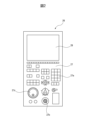
- FIG. FIG. 2 is a schematic plan view of a control panel of the machine tool in the first embodiment.
- 2 is a block diagram of a process management unit of the management device according to the first embodiment.
- FIG. FIG. 13 is a diagram illustrating status information of an operator's operation when the machine tool is stopped.
- 1 is a first image of a control chart of a manufacturing process displayed on a display unit of a management device.
- 13 is an image illustrating an operation for a worker to set a starting point of state information.
- 13 is an image illustrating an operation in which a worker sets an end point of status information.
- 13 is a second image of the control chart of the manufacturing process after an operator sets the status information.
- FIG. 11 is a diagram illustrating a determination logic for determining state information of a manufacturing process.
- FIG. 13 is a third image of the control chart of the manufacturing process after the state information of the manufacturing process has been calculated. 4 shows a moving image displayed on a display unit in the first embodiment.
- FIG. 11 is a block diagram of equipment according to a second embodiment. 13 is an image of a control chart of a manufacturing process of equipment in the second embodiment.
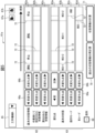
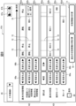
- FIG. 13 is an enlarged view of an overall process diagram of the facility in the second embodiment.
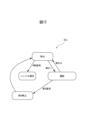
- FIG. 11 is a state transition diagram of equipment according to the second embodiment.
- a management device for managing the state of a manufacturing process in a first embodiment will be described with reference to Figures 1 to 13.
- a manufacturing process for manufacturing a product or part (semi-finished product) using at least one machine will be described.
- a numerically controlled machine tool will be taken as an example of the machine.
- FIG. 1 is a block diagram of equipment including a machine tool according to this embodiment.
- the equipment includes a machine tool 1 and a management device 4 that manages the manufacturing process of the machine tool 1.
- the machine tool 1 machines a workpiece while changing the relative position of the tool with respect to the workpiece.
- the machine tool 1 includes a machine tool body 3 that machines the workpiece.
- the machine tool body 3 has a feed axis that changes the relative position of the tool with respect to the workpiece.
- the feed axis is made up of three linear axes (X-axis, Y-axis, and Z-axis).
- the feed axis of the machine tool 1 is not limited to this form and can be made up of any linear axis or rotary axis.
- the machine tool body 3 is equipped with a moving device 11 that moves at least one of the workpiece and the tool along the feed axis.
- the moving device 11 includes feed axis motors 12 arranged corresponding to each feed axis.
- the machine tool 1 is equipped with a spindle head that holds the tool and rotates the tool.
- the spindle head includes a spindle that supports the tool, and a spindle motor 13 that rotates the spindle.
- the machine tool body 3 includes auxiliary devices 14 that assist in the machining of the workpiece.
- the auxiliary devices 14 include, for example, a supply device that supplies cutting fluid to the tool, a tool changer that automatically changes the tool, and a device that opens and closes the door.
- Each auxiliary device is equipped with a pump, a motor, a sensor, or the like.
- the machine tool 1 is equipped with a machine control device 2 that controls the machine tool main body 3.
- the machine control device 2 controls the machine tool main body 3 including the moving device 11 and the auxiliary device 14.
- the machine control device 2 includes an arithmetic processing device (computer) having a CPU (Central Processing Unit) as a processor.
- the arithmetic processing device has a RAM (Random Access Memory) and a ROM (Read Only Memory), etc., connected to the CPU via a bus.
- the machine tool 1 in this embodiment is of a numerically controlled type.
- a machining program 51 which is a program for operating the machine tool 1, is generated in advance by an operator.
- the machine control device 2 has a memory unit 21 that stores information related to machining, such as the machining program 51.
- the memory unit 21 can be configured with a non-transitory storage medium capable of storing information.
- the memory unit 21 can be configured with a storage medium such as a volatile memory, a non-volatile memory, a magnetic storage medium, or an optical storage medium.
- the machine control device 2 includes a command generating unit 22 that generates operation commands for the moving device 11 and the auxiliary device 14 based on the machining program 51.
- the command generating unit 22 corresponds to a processor that operates according to the machining program 51.
- the processor is configured to be able to read information stored in the storage unit 21.
- the processor reads the machining program 51 and performs the control defined in the machining program 51, thereby functioning as the command generating unit 22.
- the machine tool 1 includes a drive device 23 including an electrical circuit that supplies electricity to the moving device 11 and the auxiliary device 14 based on the operation command generated by the command generation unit 22.
- the drive device 23 supplies electricity to electrical equipment included in the machine tool main body 3.
- the drive device 23 supplies electricity to the moving device 11 based on the operation command, causing the feed axis motor 12 and the spindle motor 13 to drive in accordance with the machining program 51.
- FIG. 2 shows a schematic plan view of the control panel of the machine tool in this embodiment.
- the machine control device 2 includes a control panel 26 that displays information related to machining, allows the operator to input information related to machining, and allows the operator to manually operate the machine tool 1.
- the operation panel 26 includes an input section 27 for inputting information related to the machine tool 1.
- the input section 27 is composed of operating members such as a keyboard 27a including operation keys for inputting letters, numbers, etc., buttons such as an emergency stop button 27b, and a handle 27c for operating the handle.
- the operation panel 26 includes a display unit 28 that displays information about the machine tool 1.
- the display unit 28 is configured with a display panel such as a liquid crystal display panel or an organic EL (Electro Luminescence) display panel.
- the display panel When the display panel is configured with a touch panel type display panel, the display panel functions as both an input unit and a display unit.
- the worker can manually move the spindle that supports the tool or the table that supports the workpiece, etc.
- the worker can manually start and stop the auxiliary device 14.
- the management device 4 is configured with an arithmetic processing device (computer) having a CPU as a processor.
- the arithmetic processing device has a RAM (Random Access Memory) and a ROM (Read Only Memory), etc., connected to the CPU via a bus.
- the management device 4 is connected to the machine control device 2 of the machine tool 1 via a communication device.
- the management device 4 has a memory unit 48 that stores information related to the management of the manufacturing process.
- the memory unit 48 can be configured with a non-transitory storage medium capable of storing information.
- the memory unit 48 can be configured with a storage medium such as a volatile memory, a non-volatile memory, a magnetic storage medium, or an optical storage medium.
- the management device 4 includes an input unit 49 for inputting information relating to the management of the manufacturing process of the machine tool 1.
- the input unit 49 includes operating members such as a keyboard including operation keys for inputting letters, numbers, etc., and a mouse.
- the management device 4 includes a display unit 50 for displaying information relating to the management of the manufacturing process of the machine tool 1.
- the display unit 50 is configured with a display panel such as a liquid crystal display panel or an organic EL (Electro Luminescence) display panel. Note that when the display panel is configured with a touch panel type display panel, the display panel functions as both the input unit and the display unit.
- FIG. 3 shows a block diagram of the process control unit in this embodiment.
- the control device 4 includes a process control unit 31 that controls the status of the manufacturing process.
- the process control unit 31 includes a signal acquisition unit 32 that acquires a signal indicating machine status information and a signal indicating operation status information resulting from the operation of the machine by a worker.
- the signal acquisition unit 32 acquires the signal together with the time.
- the process control unit 31 includes a process creation unit 41 that generates a process including status information of each work process.
- the process creation unit 41 includes a change point generation unit 42 that generates change points in the status information of the manufacturing process based on changes in signals acquired from the machine.
- the process creation unit 41 includes a status setting unit 43 that sets status information of the operator's operation for the manufacturing process displayed on the display unit 50 in response to the operator's operation.
- the process creation unit 41 includes a logic generation unit 44 that generates judgment logic for judging status information of the work process included in the manufacturing process based on the machine status information and the operator operation status information set for the manufacturing process.
- the process creation unit 41 includes a transition diagram generation unit 45 that generates a state transition diagram based on the manufacturing process state information set by the worker.
- the process creation unit 41 includes a state correction unit 46 that corrects the state information of the worker's operation included in the manufacturing process state information in accordance with the worker's operation.
- the process management unit 31 includes a display control unit 47 that controls the display on the display unit 50.
- the display control unit 47 controls and displays the manufacturing process control chart and other information displayed on the display unit 50.
- the process management unit 31 includes a status calculation unit 36 that calculates status information of the manufacturing process using judgment logic based on either a signal indicating machine status information or a signal indicating status information of the operator's operation.
- the process management unit 31 includes a simulation execution unit 37 that performs a simulation of the manufacturing process status information generated by the machine control device and the operator's operation.
- process management unit 31, signal acquisition unit 32, state calculation unit 36, simulation execution unit 37, process creation unit 41, and display control unit 47 correspond to processors that operate according to a program.
- change point generation unit 42, state setting unit 43, logic generation unit 44, transition diagram generation unit 45, and state correction unit 46 included in the process creation unit 41 correspond to processors that operate according to a predetermined program.
- the processors load the programs and perform the controls defined in the programs, thereby functioning as the respective units.
- the display control unit 47 of the management device 4 in this embodiment displays a management diagram of the manufacturing process including status information of the manufacturing process.
- the status information indicates the content of the work performed by the machine or the worker.
- the status information of the manufacturing process includes machine status information and operation status information resulting from the worker's operation of the machine (referred to as "operator operation status information" in this embodiment).
- the machine status information includes basic machine status information defined by the manufacturer from the time of manufacturing the machine.
- the basic machine status information is set in advance at the time of purchase of the machine without the need for the worker to set it.
- the basic machine status information in this embodiment includes status information that changes based on the processing program.
- the basic machine status information includes the machine's operating status, machine's stopped status, machine's alarm status, and disconnected status information in which the power supply is cut off or communication with the outside is cut off.
- the basic machine status information is automatically determined without the worker having to set it.
- the basic status information of a machine can be determined arbitrarily by the manufacturer. For example, in addition to an alarm state, it can include an emergency stop state in which an emergency stop signal is sent and the machine stops.
- the basic status information of a machine can also include a state in which the machine is temporarily stopped by the machining program.
- the basic status information of a machine may also include the state in which the machine is operating in response to a command from the machine control device. For example, it may include a state in which MDI (Manual Data Input) is being performed, in which a program created by an operator on a control panel is executed line by line. Additionally, the warm-up operation of the machine, etc. may be set as the basic status information of the machine.
- MDI Manual Data Input
- the machine status information may include additional machine status information.
- the additional machine status information may be set for the manufacturing process in response to the operation of the worker.
- the additional machine status information is status information set by the worker.
- the additional machine status information includes stopping the machine tool by the M30 signal, which is one of the M codes in the machining program.
- the M30 signal is, for example, an M code that is transmitted when the machining program ends. The machine tool stops when the M30 signal is transmitted.
- a status information signal is transmitted from the machine control device in accordance with a predetermined program.
- FIG. 4 shows an explanatory diagram of the status information of the operator's operation in this embodiment.
- a process diagram 78 is shown, which includes operation, alarm, stop, and cut-off as basic status information of the machine.
- a signal (MSS: Machine Status Signal) indicating the status of the machine, which is sent from the command generation unit 22, is obtained and the basic status information of the machine is determined.
- MSS Machine Status Signal
- the machine tool operates when the signal MSS indicating the status becomes 1.
- the machine tool stops when the MSS becomes 2.
- signals are described for identifying the status information of various operations caused by the operator's operations and the work process (status information) during the period when the machine tool is stopped.
- the status information of operations caused by the operator's operations is shown in process diagrams 79a to 79g.
- process diagram 79a shows a handle operation in which an operator operates handle 27c on operation panel 26 to move a table, tool, etc. in a desired direction.
- the coordinate axis and the direction of movement are specified on keyboard 27a. Then, when the operator turns handle 27c, the table, etc. moves according to the amount of rotation of handle 27c.
- an HND signal is transmitted from command generating unit 22.
- Process diagram 79b shows incremental feed, in which the operator operates the keys on keyboard 27a of operation panel 26 to move a table or tool by a predetermined amount.
- an INC signal is sent from command generation unit 22.
- Process diagram 79c shows the operation in which the worker edits the machining program, etc.
- the worker can change the program or input correction values related to the program by operating keyboard 27a of operation panel 26.
- an EDIT signal is sent from command generation unit 22.
- Process diagram 79d shows the control of reference point return, in which the worker operates keyboard 27a on the operation panel 26 to move at least one of the moving target members, the tool and the table, to a specified reference point.
- the reference point is a reference point that is determined in advance by the worker.
- a REF signal is sent from the command generation unit 22.
- the operator is performing operations related to the moving device 11 of the machine tool body 3. Furthermore, the status information of the operator's operation includes status information of the operator's operation of the auxiliary device 14. Furthermore, the status information of the operator's operation includes the transmission of an M code resulting from the operator's operation.
- Process diagram 79e shows a state in which the air blow device, serving as the auxiliary device 14, is driven by the operator operating the keyboard 27a of the operation panel 26.
- the operator can blow away chips and the like inside the machining chamber of the machine tool by manually driving the air blow device.
- the command generation unit 22 transmits an AIR signal when the air blow operation is being performed.
- Process diagram 79f shows the state of the device that opens and closes the door as the auxiliary device 14 when the worker operates the keyboard 27a of the operation panel 26.
- the command generation unit 22 transmits a DOR signal when operating the door. For example, the command generation unit 22 transmits a DOR signal "0" when the door is opened, and transmits a DOR signal "1" when the door is closed.
- Process diagram 79g shows the state in which an operator presses the emergency stop button 27b on the operation panel 26 and an M code is sent.
- the M0 signal which is one of the M codes and which temporarily stops the program, is sent.
- the machine stops when the command generation unit 22 sends the M0 signal. After the cause of the emergency stop is resolved, the operator presses the start button on the operation panel 26 to start work, and work resumes.
- the M0 signal may be sent based on the machining program in addition to the operator's operation of the emergency stop button.
- the stop caused by the M0 signal corresponds to additional machine status information, not status information based on the operator's operation.
- status information of operator operations include operation of measuring equipment, attachment or removal of jigs, clamping or unclamping of a workpiece, or transport of a workpiece.
- a jog operation in which manual operation is performed by turning the dial of a manual pulse generator. In a jog operation, the operator can turn the dial to move a specific part of the device in a specific direction according to the amount of rotation of the dial.
- the management device of this embodiment displays a control chart of the manufacturing process, including basic status information of the machine, on the display unit.
- the management device sets status information of the worker's operation and additional status information of the machine for the manufacturing process according to the worker's operation.
- a control chart of the manufacturing process can be created for each type of work. For example, when cutting a product with a machine tool, this may include rough cutting, main processing, and polishing.
- a control chart can be created for each type of processing.
- FIG. 5 shows a first image of the manufacturing process displayed on the display unit of the management device in this embodiment.
- the first image 61a is a management chart including status information of the manufacturing process.
- the display control unit 47 displays the first image 61a on the display unit 50.
- the image 61a includes a status display area 62 that displays a process chart including each work process (status information), and a signal display area 63 that displays information regarding a signal obtained due to the driving of the machine by the machining program or the operation of the worker.
- buttons 67a for storing in the memory unit 48 the basic status information of the machine, the status information set by the operator, the status information calculated by the status calculation unit 36, and the signals acquired by the signal acquisition unit 32. Also arranged is a button 67b for acquiring the status information and signals stored in the memory unit 48.
- the machine tool is run, stopped, run, and stopped again.
- the second stop is based on the M30 signal. Furthermore, the manufacturing process is shown in which the operator operates the handle during the second stop period.
- a process chart 62a showing the basic status information of the machine a process chart 62b including status information of the operator's operation set by the operator and additional status information of the machine, and a process chart 62c showing status information calculated by the status calculation unit 36 are displayed.
- a judgment logic for the status information is generated based on the status information of the manufacturing process set by the operator, and the status information calculated based on the judgment logic is displayed.
- Each process diagram 62a, 62b, 62c is a horizontal bar that displays the status information of the manufacturing process. It shows the state in which work is performed from left to right as time t progresses.
- Each process diagram 62a, 62b, 62c displays a boundary line 72 that indicates the point at which the status information changes.
- the change points of the acquired signals and the types of signals are displayed over time.
- the change points of all signals acquired by the signal acquisition unit 32 are displayed as boundary lines 72.
- the signal diagram 63b of the basic machine status information the changes in the MSS, which is a signal indicating the basic machine status information, are displayed.
- signals indicating the status information of the operator's operation are displayed. For example, signals transmitted by the operator's operation, such as the HND signal, INC signal, and EDIT signal shown in FIG. 4, are displayed.
- M code signal diagram 63d M code signals transmitted from the command generation unit 22 are displayed. The change points of each signal are displayed by boundary lines 72.
- the machine tool 1 operates based on the machining program 51.
- An operator operates the operation panel 26 in accordance with the manufacturing process to perform the operation.
- the process management unit 31 acquires signals output from the command generation unit 22 and generates signal change points in the process diagram.
- the signal acquisition unit 32 acquires all signals transmitted from the command generation unit 22 to the drive unit 23.
- the signal acquisition unit can acquire signals related to status information from any device. For example, if the machine includes a PMC (Programmable Machine Controller), the signal acquisition unit may acquire signals from the PMC. Alternatively, the signal acquisition unit may acquire signals indicating the status from a sensor attached to the machine.
- PMC Programmable Machine Controller
- the change point generation unit 42 detects signal changes and generates change points.
- the display control unit 47 displays all acquired signal change points as boundary lines 72 on the signal diagram 63a of the change points.
- the display control unit 47 also displays boundary lines 72 of all signal changes on the process diagram 62b of the status information set by the worker. By implementing this control, it is possible to automatically set change points of the status information. The worker can easily set the status information in the next definition process.
- the display control unit 47 also displays signals and boundary lines 72 as change points in each of the signal diagrams 63b to 63d in the signal display area 63.
- the signal acquisition unit 32 acquires a handle operation signal HND as status information of the operator's operation, and an M30 signal as additional status information of the machine.
- the display control unit 47 displays the handle operation signal in the operation mode signal diagram 63c in the signal display area 63.
- the display control unit 47 also displays the M30 signal in the M code signal diagram 63d. If there are not enough signal types, the operator may add a signal type by pressing the add button 69.
- the basic status information of the machine is determined in advance without the operator having to set it.
- the signal acquisition unit 32 acquires the MSS, which is a signal indicating the basic status information of the machine, and the display control unit 47 displays the signal type and signal change points in the signal diagram 63b.
- the status setting unit 43 of the process creation unit 41 automatically determines the basic status information of the machine based on the MSS.
- the display control unit 47 displays the basic status information of the machine in the process diagram 62a.
- the first image 61a shows the state in which the basic machine status information has been acquired.
- the process diagram 62a for the basic machine status information displays "Running” and "Stopped.” In this way, the status setting unit 43 of the process creation unit 41 can automatically set the basic machine status information for the manufacturing process based on the signal indicating the basic machine status information.
- Figure 6 shows an image explaining the process in which the worker sets the starting point of the status information.
- the worker performs a definition process in which the worker sets the status information of the worker's operation and additional status information of the machine.
- the worker sets the status information of the manufacturing process.
- the status information of the handle operation during the second stop period is set in the process chart 62b.
- the worker selects one boundary line 72a in the process diagram 62b that corresponds to the start point of the steering operation. For example, the worker selects one boundary line 72a with buttons 66a and 66b.
- the display control unit 47 displays a signal addition image 75 that sets the conditions for determining the start of the steering operation.
- the status setting unit 43 can generate conditions for determining the status information of the steering operation according to the operation of the worker. If the only signal for determining the steering operation in the signal addition image 75 is the HND signal, the worker can check the display and close the signal addition image 75.
- the state setting unit 43 can set additional conditions for determining steering operation as state information.
- the conditions for determining that steering operation is being performed may include that the door is open.
- the worker can add a condition to the signal addition image 75 where the DOR signal is 0, which is transmitted when the door is open. In this case, it can be determined that steering operation is being performed when the HND signal is 1 and the DOR signal is 0.
- the worker selects a boundary line that corresponds to the start point of each piece of status information. Then, the status setting unit 43 can set the conditions for judging the status information according to the worker's operation.
- Figure 7 shows an image explaining the process by which a worker sets the end point of the status information.
- the worker selects a boundary line 72b that corresponds to the end point of the steering wheel operation in the process flow chart 62b.
- the display control unit 47 displays a name setting image 76 for setting a name for the status information.
- the worker can select a name such as "Stop" from the name setting image 76.
- the worker can set an arbitrary name by selecting the new creation button.
- the worker sets the name of the status information to "steering wheel operation”.
- the worker can set the start and end points for the M30 signal in the process flow chart 62b by performing operations similar to those for setting the status information of the steering wheel operation.
- the status setting unit 43 can set status information based on signals indicating machine status information and signals indicating status information of the operator's operation.
- the status setting unit 43 sets the start point and end point of each piece of status information in the process flow chart 62b of the manufacturing process.
- the status setting unit 43 can set the signal conditions for starting each piece of status information.
- the status setting unit 43 can set the name of the status information.
- the signal type and the name of the status information are predetermined, so the worker does not need to set it.
- the status setting unit 43 automatically sets the basic machine status information for the process chart 62b.
- additional machine status information such as M-code signals like M30 and status information of the worker's operation such as handle operation
- the status setting unit 43 sets the status information for the manufacturing process in accordance with the worker's operation, as described above.
- FIG. 8 shows a second image after the status setting unit has set the status information in response to the operator's operation.
- the status information set by the status setting unit 43 is displayed for the process chart 62b.
- the management device 4 of this embodiment can set the process chart of the manufacturing process by combining the status information automatically set by the machine and the status information manually set by the operator.
- FIG. 9 shows a logic diagram for determining a change in status information.
- the logic generation unit 44 of the process creation unit 41 generates judgment logic for determining the status of the manufacturing process based on the basic status information of the machine set for the manufacturing process, additional status information of the machine, and status information of the operator's operation.
- the logic generation unit 44 generates judgment logic for determining a change in status information based on the status information before the transition, the status information after the transition, and signals related to the status information.
- the logic generation unit 44 generates judgment criteria for determining a change in status information based on the status information of the process chart 62b set by the status setting unit 43.
- the first logic indicates a change in status information when the machine tool 1 stops from a state in which it is operating according to the machining program 51.
- the MSS becomes 2 during the operation period, it can be determined that the status information transitions to stopped.
- the judgment logic shown in FIG. 9 is shown in a table, it is not limited to this form. It may be stored in the memory unit depending on the program format. The judgment logic created by the logic generation unit 44 is stored in the memory unit 48.
- status calculation unit 36 acquires one of a signal indicating basic status information of the machine, a signal indicating additional status information of the machine, and a signal indicating status information of the operator's operation. Status calculation unit 36 calculates status information of the manufacturing process based on these signals and the judgment logic generated by logic generation unit 44.
- FIG. 10 shows a third image of the manufacturing process control chart displaying the status information calculated by the status calculation unit.
- the display control unit 47 displays the status information of the manufacturing process calculated by the status calculation unit 36 on the display unit 50.
- the start point, end point, and name of each piece of status information are displayed in the process chart 62c.
- the calculated manufacturing process flow chart 62c should be the same as the manufacturing process flow chart 62b set by the worker. The worker can check whether the status information calculated by the status calculation unit 36 is correct.
- the worker can store in memory 48 process flow chart 62a of the basic status information of the machine, process flow chart 62b of status information set by the worker, and process flow chart 62c of status information calculated by status calculation unit 36.
- the signal and time displayed in signal display area 63 can also be stored in memory 48 at the same time.
- the machine tool 1 in this embodiment includes a camera 15 that captures video.
- the camera 15 in this embodiment is configured to capture video.
- the camera 15 in this embodiment captures at least one of the inside of the machine, the outside of the machine, and the worker.
- the camera 15 captures images based on commands from the command generation unit 22.
- Figure 11 shows an example of a video captured by a camera.
- Video 90 captures images of a worker 91, a workpiece 92, and a door 93 that opens and closes the machining chamber.
- Video 90 captured by camera 15 is stored in memory unit 48 together with the time. For example, during the investigation process in which change point generation unit 42 acquires change points, the camera 15 can capture images of the worker and the machine tool while the work is being performed.
- the display control unit 47 can display the video 90 on the display unit 50 in accordance with the time on the flow chart of the manufacturing process. For example, when the worker sets the start point or end point of the status information, the video 90 can be displayed in accordance with the time of the start point or the time of the end point.
- the display control unit 47 can display the video 90 in synchronization with the time of the boundary line of the status information.
- the worker may specify the time on the flow chart of the manufacturing process and display the video 90. The worker can check each work process by watching the video. In this way, by having the worker set the status information while the video is displayed, errors in setting the status information can be reduced.
- the camera in this embodiment is a camera that captures video, but is not limited to this form.
- the camera may be a camera that captures still images. Even in the case of a camera that captures still images, it is preferable to store the still images together with the time so that the images can be displayed in synchronization with the process flow chart of the manufacturing process. Note that although the machine in this embodiment is equipped with a camera, this is not limited to this form, and the machine does not necessarily have to be equipped with a camera.
- FIG. 12 shows a state transition diagram of a manufacturing process generated by the process creation unit.
- the process creation unit 41 in this embodiment includes a transition diagram generation unit 45 that generates a state transition diagram.
- the transition diagram generation unit 45 generates a state transition diagram 81a based on at least one of the state information set by the state setting unit 43 in response to the operation of the operator and the judgment logic generated by the logic generation unit 44.
- the state transition diagram 81a is formed to correspond to the transition of state information in the process diagram 62b shown in FIG. 10. For example, when the MSS becomes 0, a transition occurs from the operating state to the stopped state. Next, when the MSS becomes 1, a transition occurs from the stopped state to the operating state.
- the state transition diagram 81a is created after the state setting unit 43 has completed setting the state information.
- the state transition diagram 81a can be displayed on the display unit 50. By displaying the state transition diagram 81a on the display unit 50, it is possible to accurately determine whether the state information set by the operator's operation is correct.
- the worker can determine whether or not state information of the worker's operation is missing. Or, the worker can determine whether or not the state information set is duplicated. Or, the worker can confirm whether or not the state information calculated by the state calculation unit 36 is correct. Note that the transition diagram creation unit does not have to be arranged in the management device, and a state transition diagram does not have to be created.
- FIG. 13 shows an image when a simulation is being performed on the transition of status information of the manufacturing process.
- an operator can perform a verification process to check whether the created process chart of the manufacturing process is correct.
- the process management unit 31 of this embodiment includes a simulation execution unit 37 that performs a simulation of the transition of status information.
- the display control unit 47 displays a slide bar 73 on the image 61d when performing the simulation.
- the display control unit 47 can also display a video 90 on the display unit 50 together with the image 61d.
- the worker moves the slide bar 73 as shown by the arrow 98 by operating the input unit 49 of the management device 4.
- the simulation execution unit 37 obtains the time corresponding to the slide bar 73.
- the simulation execution unit 37 transmits this time to the display control unit 47.
- the display control unit 47 displays a video 90 corresponding to the time.
- the simulation execution unit 37 displays the video 90 in synchronization with the movement of the slide bar 73.
- the worker can check whether the status information of the process chart 62b set by the worker's operation is correct. In particular, the worker can check whether the start point, end point, and name of the status information are correct.
- the worker moves the slide bar 73.
- the status information is displayed in the process diagram 62c.
- the simulation execution unit 37 acquires the time of the slide bar 73.
- the simulation execution unit 37 transmits this time to the display control unit 47.
- the display control unit 47 displays the video 90 at the time corresponding to the time of the slide bar 73. The worker can check whether the status information calculated by the status calculation unit 36 is correct while watching the video 90.
- the movement of the slide bar and the playback of the video can be synchronized to simulate the transition of the status information set by the status setting unit in response to the operator's operation.
- the transition of the status information calculated by the status calculation unit can be confirmed. It can be confirmed whether the status information is transitioning as the operator desires.
- the simulation execution unit 37 plays the video 90 and obtains the current time from the video 90.
- the simulation execution unit 37 transmits this time to the display control unit 47.
- the display control unit 47 may then move the slide bar 73 of the image 61d according to the time obtained from the video 90.
- the worker can then check whether the status information set by the status setting unit 43 through the worker's operation or the status information calculated by the status calculation unit 36 corresponds to the video 90.
- the display control unit 47 may display the state transition diagram 81a on the display unit 50.
- the simulation execution unit 37 acquires state information where the slide bar 73 is positioned from the control chart of the manufacturing process.
- the display control unit 47 displays a mark indicating the current state information on the state transition diagram 81a. The worker can check whether the state information on the state transition diagram 81a is correct.
- the signal acquisition unit 32 acquires a signal from the machine control device 2 each time an actual task is performed.
- the state calculation unit 36 calculates the state information of the results based on the signal from the command generation unit 22.
- the signal acquisition unit 32 stores signals from the machine control device 2 in the memory unit 48 each time actual work is performed.
- the memory unit 48 stores signals indicating the state of past manufacturing processes, including signals indicating machine state information and signals indicating operation state information.
- the worker can call up signals indicating the state information of the manufacturing process previously acquired from the memory unit 48 by pressing button 67b. Then, by pressing the button 70 to recalculate past state information, the state calculation unit 36 calculates the state information included in the past manufacturing process based on the signals indicating the state of the past manufacturing process.
- the state calculation unit 36 calculates the transition of the past state information.
- the display control unit 47 displays the status information of the past manufacturing process calculated by the status calculation unit 36 on the process diagram 62c.
- the status information of the manufacturing process calculated by the status calculation unit 36 is actual status information.
- the worker can compare the status information from multiple manufacturing processes. The worker can then examine problems in the manufacturing process.
- a worker may change tools before using a machine to perform processing.
- the jig that holds the tool can be improved.
- the timing of tool replacement can be changed. In this way, improvements to each work process included in the manufacturing process can be considered based on the time for the work process calculated from the actual work (transition of state information).
- the process creation unit 41 of this embodiment includes a status correction unit 46 that corrects past status information.
- the status correction unit 46 can correct the status information of the worker's operation, which is included in the status information of the manufacturing process, in accordance with the worker's operation.
- the memory unit 48 stores past status information of the manufacturing process, including past machine status information and status information of the operator's operation. With reference to FIG. 10, the operator presses button 67b to obtain status information of the past manufacturing process.
- the display control unit 47 displays the status information of the past manufacturing process on the display unit 50. For example, an image similar to image 61c shown in FIG. 10 is displayed.
- the status correction unit 46 can correct the status information of the process diagram 62b set by the worker according to the operation of the worker.
- the operation of the worker to correct the status information of the manufacturing process is the same as the operation to set the status information of the manufacturing process in the definition process.
- the worker selects the boundary line 72 of the status information to be changed.
- the status correction unit 46 can correct the start point, end point, and name of the status information according to the operation of the worker. For example, if the end point of the status information operated by the worker is incorrect, the position of the end point can be corrected. Or, the signal conditions at the start point can be corrected to determine the status information.
- the logic generation unit 44 can generate judgment logic for judging the status information based on the corrected status information. Then, when the worker presses a button 70 for recalculating the past status information, the status calculation unit 36 acquires a signal indicating the status information of the actual past manufacturing process. The status calculation unit 36 calculates the status information included in the past manufacturing process based on the corrected judgment logic and the signal indicating the status information of the past manufacturing process. The display control unit 47 displays the calculated status information on the process diagram 62c.
- the process management unit 31 of this embodiment can correct previously set status information. Then, based on the corrected status information, it calculates actual status information for multiple past manufacturing processes. The worker can refer to the calculated status information and consider improvements to the manufacturing process.
- a numerically controlled machine tool having multiple feed axes is used as an example of the machine, but the present invention is not limited to this form.
- Machine tools include, for example, drill presses and lathes having a single feed axis.
- Any machine controlled by a numerical control device can be used as the machine.
- a machine equipped with a work tool that performs work on a workpiece and a multi-joint robot that changes the position and attitude of the work tool can be used.
- an injection molding machine, an electric discharge machine, a laser processing machine, a wire electric discharge machine, etc. can be used as the machine.
- an arithmetic processing device connected to the machine control device via a communication device functions as a management device, but this is not limited to this form.
- the machine control device may function as a management device that manages the manufacturing process.
- the machine control device may be equipped with a process management unit.
- the processor of the machine control device functions as the process management unit.
- the memory unit of the machine control device functions as the memory unit of the management device.
- the input unit and display unit of the operation panel function as the input unit and display unit of the management device.
- the display unit that displays the process chart of the manufacturing process is the display unit of the management device, but is not limited to this form.
- the control chart of the manufacturing process can be displayed on any display unit.
- the control chart of the manufacturing process can be displayed on a display unit arranged on an operation panel.
- the management device in the second embodiment manages the state of a manufacturing process in a facility including a plurality of machines.
- FIG. 14 shows a block diagram of the facility in this embodiment.
- the facility in this embodiment includes a first machine tool 1a and a second machine tool 1b as multiple machines.
- the first machine tool 1a and the second machine tool 1b in this embodiment are the same machine tool and perform the same work. In other words, the same machine tools are arranged in parallel.
- the facility includes a management device 4 that manages the manufacturing processes of the first machine tool 1a and the second machine tool 1b.
- the management device 4 in this embodiment is connected to the first machine tool 1a and the second machine tool 1b via a communication device.
- the management device is not limited to this form. Either the machine control device of the first machine tool 1a or the machine control device of the second machine tool 1b may function as the management device.
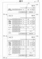
- FIG. 15 shows a control chart of the manufacturing process of the equipment displayed on the display unit of the management device.
- Image 56 of the equipment control chart displays the control charts of the multiple machines that make up the equipment.
- Image 56 displays image 61c of the control chart of the manufacturing process of machine tool A, which is the first machine tool 1a, and image 61e of the control chart of the manufacturing process of machine tool B, which is the second machine tool 1b.
- Each of images 61c, 61e is similar to the image of the control chart of the manufacturing process of the machine tool in the first embodiment.
- image 56 of the equipment control chart includes image 61f that displays status information of the entire manufacturing process of the equipment.
- FIG. 16 shows an enlarged image of an image showing the status information of the entire manufacturing process of the equipment.
- Image 61f includes a process chart 62d of the overall status information set by the worker.
- Process chart 62d displays status information that combines the status information of multiple machines.
- the status setting unit 43 sets equipment status information for the entire manufacturing process of the equipment in response to the operator's operations.
- the operator sets the status information of the equipment process flow chart 62d in the same manner as the operator sets the status information of the operation in the process flow chart 62b (see Figure 8) of the manufacturing process of each machine.
- the operator sets the signal conditions at the start point of each piece of equipment status information.
- the operator sets the name of the status information at the end point of the status information. For example, if at least one of the multiple machines is operating, a condition can be set that the overall status information of the equipment is operating.
- Image 61f displays a "Calculate status information" button 71 for calculating the equipment status information and a "Recalculate past status information” button 70. Also provided are a button 67a for storing the equipment status information in memory unit 48 and a button 67b for calling up the status information stored in the memory unit. By operating these buttons, it is possible to calculate the status information of the entire equipment, or to recalculate past status information based on past actual status information and signals, just like in the control chart of a machine's manufacturing process. Alternatively, it is possible to modify the overall status information of the equipment that was set in the past.
- image 61f of the process chart of the entire manufacturing process of the facility can be displayed together with images 61c, 61e of the control chart of the manufacturing processes of multiple machines. Furthermore, the worker can display or hide images 61c, 61e of the machine control charts by operating button 57a. In other words, the worker can display only the desired machines. Furthermore, by operating button 57b, a machine that manages the manufacturing process can be added.
- the status calculation unit 36 of the process management unit 31 may be configured to calculate status information of the work actually performed for the entire process chart of the equipment.
- the process chart of the status information calculated by the status calculation unit 36 may be displayed below the process chart 62d of the image 61f.
- the worker can examine each work process included in the manufacturing process. For example, it is possible to calculate the operating rate, non-defective rate, and first-pass rate (the ratio of products that pass all inspections in the manufacturing process in one go) for each group including multiple machines, rather than just for a single machine.
- the simulation execution unit 37 can execute a simulation of the transition of state information, similar to the first embodiment.
- the display control unit 47 displays a slide bar 73 on the process diagram of the manufacturing process.
- the simulation execution unit 37 acquires the time corresponding to the position of the slide bar 73.
- the display control unit can display a video or still image corresponding to the time of the slide bar 73 on the display unit 50.
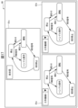
- Figure 17 shows the equipment state transition diagram in this embodiment.
- the transition diagram generation unit 45 of the process control unit 31 generates an overall equipment state transition diagram 81c.
- the image 80 also generates an overall equipment state transition diagram 81c. In this way, the process control unit 31 can create and display an overall state transition diagram.
- marks can be displayed in the state transition diagrams 81a, 81b, and 81c according to the position of the state information on the slide bar 73.
- Equipment control charts can also be generated for equipment in which multiple different machines are arranged in series. For example, in the case of equipment that includes a first machine, a second machine, a third machine, an intermediate warehouse, a fourth machine, and a fifth machine, these machines can be arranged in series.
- one product is manufactured every two hours. For example, if the first machine stops for one minute once every 30 minutes, the status information of the facility's entire manufacturing process becomes "Stopped.” However, there is an intermediate warehouse downstream of the first machine. Since products are manufactured at a rate of one product every two hours, there is no delay in the production of the products. On the other hand, if a fourth machine in the work process downstream of the intermediate warehouse stops, causing the overall status information of the facility to become "Stopped,” a delay will occur in the production of the products. By creating a process diagram that shows the overall status information of the facility, it is easy to identify problematic processes in the production of products.
- the management device of at least one of the above-mentioned embodiments can set and display detailed status information included in the process flow chart of the manufacturing process. As a result, workers can study and improve the manufacturing process in detail.
- a management device 4 for managing the state of a manufacturing process a display unit 50 for displaying machine status information including predetermined basic status information of the machines 1, 1a, and 1b, and manufacturing process status information including operation status information resulting from an operator's operation of the machines; a signal acquiring unit 32 for acquiring a signal indicating machine status information and a signal indicating operator operation status information; and a status setting unit that sets status information of an operator's operation for the manufacturing process displayed on the display unit in accordance with the operator's operation based on a signal indicating the machine status information acquired by the signal acquisition unit and a signal indicating the operator's operation.
- the basic state information of the machine indicates the state in which the machine is operating based on the program 51,
- the machine status information includes additional machine status information;
- the status setting unit automatically sets basic status information of the machine for the manufacturing process based on a signal indicating the basic status information of the machine, and further sets additional status information of the machine for the manufacturing process in response to operation by an operator.
- (Appendix 3) a logic generating unit (44) that generates a judgment logic for judging status information of a manufacturing process based on machine status information and operator operation status information set for the manufacturing process; a status calculation unit 36 that calculates status information of the manufacturing process by a judgment logic based on either a signal indicating status information of the machine or a signal indicating status information of an operator's operation, 3.
- the management device according to claim 1, wherein the display unit displays the status information of the manufacturing process calculated by the status calculation unit.
- the display unit displays status information of past manufacturing processes, 4.
- the management device according to claim 1, wherein the status correction unit corrects status information of an operator's operation included in the status information of the manufacturing process in response to the operator's operation.
- (Appendix 5) a storage unit 48 for storing video images of at least one of the inside of the machine, the outside of the machine, and a worker; 4.
- a change point generating unit 42 for generating a change point of status information of a manufacturing process based on a change in a signal acquired from a machine;
- the display unit displays the change points generated by the change point generation unit on a process chart 62b of the manufacturing process, 6.
- the management device according to claim 1, wherein the state setting unit sets state information of the operator's operation based on the change point.
- a management device 4 for managing a manufacturing process of a facility including a plurality of machines The display unit displays status information of the manufacturing process of each of the machines 1a and 1b and status information of the manufacturing process of the entire facility, 7.
Landscapes
- Engineering & Computer Science (AREA)
- Physics & Mathematics (AREA)
- General Physics & Mathematics (AREA)
- Automation & Control Theory (AREA)
- General Engineering & Computer Science (AREA)
- Manufacturing & Machinery (AREA)
- Quality & Reliability (AREA)
- General Factory Administration (AREA)
Priority Applications (2)
| Application Number | Priority Date | Filing Date | Title |
|---|---|---|---|
| PCT/JP2022/045160 WO2024121991A1 (ja) | 2022-12-07 | 2022-12-07 | 管理装置 |
| JP2024562490A JPWO2024121991A1 (https=) | 2022-12-07 | 2022-12-07 |
Applications Claiming Priority (1)
| Application Number | Priority Date | Filing Date | Title |
|---|---|---|---|
| PCT/JP2022/045160 WO2024121991A1 (ja) | 2022-12-07 | 2022-12-07 | 管理装置 |
Publications (1)
| Publication Number | Publication Date |
|---|---|
| WO2024121991A1 true WO2024121991A1 (ja) | 2024-06-13 |
Family
ID=91378924
Family Applications (1)
| Application Number | Title | Priority Date | Filing Date |
|---|---|---|---|
| PCT/JP2022/045160 Ceased WO2024121991A1 (ja) | 2022-12-07 | 2022-12-07 | 管理装置 |
Country Status (2)
| Country | Link |
|---|---|
| JP (1) | JPWO2024121991A1 (https=) |
| WO (1) | WO2024121991A1 (https=) |
Citations (3)
| Publication number | Priority date | Publication date | Assignee | Title |
|---|---|---|---|---|
| JP2019016226A (ja) * | 2017-07-07 | 2019-01-31 | 株式会社日立製作所 | 作業データ管理システム及び作業データ管理方法 |
| JP2020052465A (ja) * | 2018-09-21 | 2020-04-02 | キヤノン株式会社 | 工程推定装置および工程推定方法 |
| WO2021006183A1 (ja) * | 2019-07-10 | 2021-01-14 | コニカミノルタ株式会社 | 作業分類システムおよび作業分類プログラム |
-
2022
- 2022-12-07 JP JP2024562490A patent/JPWO2024121991A1/ja active Pending
- 2022-12-07 WO PCT/JP2022/045160 patent/WO2024121991A1/ja not_active Ceased
Patent Citations (3)
| Publication number | Priority date | Publication date | Assignee | Title |
|---|---|---|---|---|
| JP2019016226A (ja) * | 2017-07-07 | 2019-01-31 | 株式会社日立製作所 | 作業データ管理システム及び作業データ管理方法 |
| JP2020052465A (ja) * | 2018-09-21 | 2020-04-02 | キヤノン株式会社 | 工程推定装置および工程推定方法 |
| WO2021006183A1 (ja) * | 2019-07-10 | 2021-01-14 | コニカミノルタ株式会社 | 作業分類システムおよび作業分類プログラム |
Also Published As
| Publication number | Publication date |
|---|---|
| JPWO2024121991A1 (https=) | 2024-06-13 |
Similar Documents
| Publication | Publication Date | Title |
|---|---|---|
| JP5817256B2 (ja) | 機械制御プログラム作成装置 | |
| CN107300891B (zh) | 参数设定装置以及参数设定方法 | |
| CN107077124B (zh) | 机床的控制方法以及机床的控制装置 | |
| US7848851B2 (en) | Controller of work piece-conveying robot | |
| US11048215B2 (en) | Tool selecting apparatus and machine learning device | |
| CN105320064B (zh) | 具有设备异常履历的解析支援功能的数值控制装置 | |
| US20110015771A1 (en) | Numerically controlling apparatus | |
| CN104285191B (zh) | 数控装置 | |
| US7218989B2 (en) | Machine tool control apparatus | |
| JP2006085328A5 (https=) | ||
| JPS59184911A (ja) | 工作物輪郭に工具を倣わせる方法 | |
| JP2006085328A (ja) | 工作機械制御装置 | |
| JP2019144828A (ja) | 数値制御装置 | |
| JP2021096561A (ja) | 制御装置、計測システム、計測方法 | |
| JP2010247246A (ja) | 数値制御装置 | |
| JP2762788B2 (ja) | 移動体の動作表示装置及びその表示方法 | |
| CN107436589A (zh) | 具备用于解决警报的程序修正支援功能的数值控制装置 | |
| JP7794961B2 (ja) | 数値制御装置およびコンピュータ読み取り可能な記憶媒体 | |
| WO2024121991A1 (ja) | 管理装置 | |
| CN117980838A (zh) | 数值控制装置 | |
| KR102633846B1 (ko) | 다품종 소량생산 제품의 생산성 향상을 위한 선반 자동 제어 시스템 및 그 방법 | |
| JP2021144284A (ja) | 加工プログラムの管理装置、管理システム、管理方法 | |
| JP2013114425A (ja) | 数値制御装置 | |
| CN118103782A (zh) | 加工面推定装置以及计算机可读取的存储介质 | |
| CN118525254A (zh) | 信息生成装置和计算机可读取的存储介质 |
Legal Events
| Date | Code | Title | Description |
|---|---|---|---|
| 121 | Ep: the epo has been informed by wipo that ep was designated in this application |
Ref document number: 22967841 Country of ref document: EP Kind code of ref document: A1 |
|
| WWE | Wipo information: entry into national phase |
Ref document number: 2024562490 Country of ref document: JP |
|
| NENP | Non-entry into the national phase |
Ref country code: DE |
|
| 122 | Ep: pct application non-entry in european phase |
Ref document number: 22967841 Country of ref document: EP Kind code of ref document: A1 |