WO2024121947A1 - ロボット用操作装置およびロボット - Google Patents
ロボット用操作装置およびロボット Download PDFInfo
- Publication number
- WO2024121947A1 WO2024121947A1 PCT/JP2022/044953 JP2022044953W WO2024121947A1 WO 2024121947 A1 WO2024121947 A1 WO 2024121947A1 JP 2022044953 W JP2022044953 W JP 2022044953W WO 2024121947 A1 WO2024121947 A1 WO 2024121947A1
- Authority
- WO
- WIPO (PCT)
- Prior art keywords
- handle
- robot
- plate portion
- flat plate
- bracket
- Prior art date
- Legal status (The legal status is an assumption and is not a legal conclusion. Google has not performed a legal analysis and makes no representation as to the accuracy of the status listed.)
- Ceased
Links
Images







Classifications
-
- B—PERFORMING OPERATIONS; TRANSPORTING
- B25—HAND TOOLS; PORTABLE POWER-DRIVEN TOOLS; MANIPULATORS
- B25J—MANIPULATORS; CHAMBERS PROVIDED WITH MANIPULATION DEVICES
- B25J9/00—Program-controlled manipulators
- B25J9/0081—Program-controlled manipulators with leader teach-in means
-
- B—PERFORMING OPERATIONS; TRANSPORTING
- B25—HAND TOOLS; PORTABLE POWER-DRIVEN TOOLS; MANIPULATORS
- B25J—MANIPULATORS; CHAMBERS PROVIDED WITH MANIPULATION DEVICES
- B25J13/00—Controls for manipulators
- B25J13/02—Hand grip control means
-
- G—PHYSICS
- G05—CONTROLLING; REGULATING
- G05B—CONTROL OR REGULATING SYSTEMS IN GENERAL; FUNCTIONAL ELEMENTS OF SUCH SYSTEMS; MONITORING OR TESTING ARRANGEMENTS FOR SUCH SYSTEMS OR ELEMENTS
- G05B19/00—Program-control systems
- G05B19/02—Program-control systems electric
- G05B19/42—Recording and playback systems, i.e. in which the program is recorded from a cycle of operations, e.g. the cycle of operations being manually controlled, after which this record is played back on the same machine
- G05B19/423—Teaching successive positions by walk-through, i.e. the tool head or end effector being grasped and guided directly, with or without servo-assistance, to follow a path
Definitions
- This disclosure relates to a robot operating device and a robot.
- a tool such as a hand is fixed to a flange at the very front of the robot along the axis of rotation of the flange, and the two handles extend on either side of the central plane of the tool (a plane that extends perpendicular to the direction in which the fingers open and close through the center of the two fingers of the hand). This allows a worker standing in front of the tool to grasp each of the two handles with both hands.
- the two handles protruding from either side of the central plane of the tool are arranged along the same plane, operability may be poor. If the two handles are arranged along the same plane, the force applied to the handles for rotational movement of the tool about an axis parallel to the plane and translational movement of the tool may be similar, making it difficult to operate with precision. Therefore, it is desirable to improve the operability of a robot that can position the tool with precision.
- One aspect of the present disclosure is a robot operating device that is attached to a robot, the robot being operable by lead-through control that detects a force applied by an operator and changes its position and posture in response to the detected force, the robot operating device comprising a bracket for attaching a tool to a flange at the tip of the robot, and a first handle and a second handle that are fixed to the bracket and held by the operator, the first handle being disposed in a form extending along a direction intersecting the rotation axis of the flange, and the second handle being disposed in a form extending in a direction intersecting the rotation axis on a plane that includes the rotation axis and is parallel to the direction in which the first handle extends.
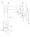
- FIG. 1 is a side view showing a robot according to an embodiment of the present disclosure, the robot having a laser processing head attached thereto.
- FIG. 2 is a front view showing the robot of FIG. 1 .
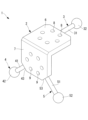
- 2 is a perspective view showing a robot operating device according to an embodiment of the present disclosure provided on the robot of FIG. 1 .
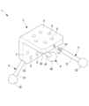
- FIG. 4 is an exploded perspective view illustrating an example of mounting a handle to a bracket of the robot operating device of FIG. 3.
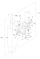
- 4 is a perspective view showing a state in which the robot operating device of FIG. 3 is attached to a flange and a laser processing head.
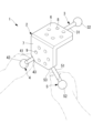
- FIG. 4 is a perspective view showing a state in which an operator is holding the grips of a second handle and a third handle of the robot operating device of FIG. 3 with both hands.
- 7 is a perspective view showing an example of a direction in which the robot moves due to a force applied by both hands of an operator to a grip of the robot operating device of FIG. 6.
- 7 is a perspective view showing another example of the direction of movement of the robot due to the force applied by both hands of the operator to the grip of the robot operating device of FIG. 6.
- 7 is a perspective view showing another example of the direction of movement of the robot due to the force applied by both hands of the operator to the grip of the robot operating device of FIG. 6.
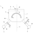
- 7 is a front view showing an example of a direction in which the robot moves due to a force applied by both hands of an operator to grip portions of the second handle and the third handle of the robot operating device of FIG. 6.
- FIG. 7 is a perspective view showing another example of the direction of movement of the robot caused by the force applied by both hands of the operator to the gripping portions of the second handle and the third handle of the robot operating device of FIG. 6 .
- FIG. 7 is a side view showing another example of the direction of movement of the robot due to the force applied by both hands of the operator to the gripping portions of the second handle and the third handle of the robot operating device of FIG. 6.
- 7 is a side view showing another example of the direction of movement of the robot due to the force applied by both hands of the operator to the gripping portions of the second handle and the third handle of the robot operating device of FIG. 6.
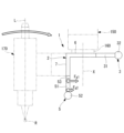
- 4 is a perspective view showing a state in which an operator is holding grips of a first handle and a second handle of the robot operating device of FIG.
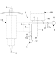
- FIG. 15 is a side view showing an example of the direction of movement of the robot due to the force applied by both hands of an operator to the holding portion of the first handle and the grip of the second handle of the robot operating device of FIG. 14.
- 15 is a perspective view showing another example of the direction of movement of the robot caused by the force applied by both hands of an operator to the holding portion of the first handle and the grip of the second handle of the robot operating device of FIG. 14 .
- FIG. 4 is a perspective view showing a state in which the robot operating device of FIG. 3 is attached to a flange and a welding torch.
- a robot manipulation device 1 and a robot 100 according to an embodiment of the present disclosure will be described below with reference to the drawings.
- the robot 100 according to this embodiment has a built-in sensor that detects a force applied by an operator.
- the robot 100 can be operated by a lead-through control that changes the position and posture of the robot 100 according to the magnitude and direction of the force detected by the sensor.
- the robot 100 is, for example, a vertical six-axis articulated robot as shown in Figures 1 and 2.
- the robot 100 includes a base 110 that is placed on an installation surface such as a floor surface, and a rotating body 120 that is supported on the base 110 so as to be rotatable about a first axis A.
- the robot 100 also includes a first arm 130 supported on the rotating body 120 so as to be rotatable about a second axis B, and a second arm 140 supported on the first arm 130 so as to be rotatable about a third axis C.
- the robot 100 also includes a three-axis wrist unit 150 supported on the tip of the second arm 140.
- the wrist unit 150 has a flange 160 that can rotate around the most distal rotation axis (sixth axis) X.
- the robot 100 according to this embodiment has a robot operating device 1 fixed to the flange 160.
- the robot operating device 1 includes a bracket 2 fixed to a flange 160, and three handles (first to third handles) 3, 4, and 5 fixed to the bracket 2.
- the bracket 2 is a member for fixing a long tool such as a laser processing head 170 (hereinafter, in this embodiment, referred to as the laser processing head 170) to the flange 160.
- the bracket 2 comprises a flat first flat portion 6 fixed to the flange 160, and a flat second flat portion 7 to which the laser processing head 170 is fixed.
- the first flat portion 6 and the second flat portion 7 are each formed in a rectangular shape.
- the bracket 2 has an L-shape in which one side of the first flat portion 6 and the second flat portion 7, which are arranged at an angle of 90° to each other, are integrally joined.
- the first flat plate portion 6 has a plurality of through holes 8 through which bolts are passed to be fastened to screw holes (not shown) provided in the flange 160.
- the second flat plate portion 7 has a plurality of through holes 9 through which bolts are passed to be fastened to screw holes (not shown) provided in the laser processing head 170.
- the bracket 2 can be fixed to the flange 160 by fastening a bolt that has been inserted through the through hole 8 of the first flat plate portion 6, whose outer surface is in intimate contact with the surface of the flange 160, into a screw hole in the flange 160. Also, a bolt that has been inserted through the through hole 9 of the second flat plate portion 7, whose outer surface is in intimate contact with the surface of the laser processing head 170, is fastened into a screw hole in the laser processing head 170. This allows the laser processing head 170 to be fixed to the bracket 2.
- the three handles 3, 4, 5 each have a gripping portion 31, 41, 51 that is held by the operator, and a spherical grip (protruding portion) 32, 42, 52 provided at one end of the gripping portion 31, 41, 51 in the longitudinal direction.
- the gripping portions 31, 41, 51 are preferably round bar-shaped with a circular cross section, but may have any other shape.
- the thickness and length of the gripping portions 31, 41, 51 may be arbitrary, but it is preferable that they have an outer diameter dimension that allows the thumb and index finger to overlap when the operator holds the gripping portion with either the left or right hand, and a length dimension that is equal to or greater than the width of the operator's fist.
- the grips 32, 42, 52 have an outer diameter dimension larger than that of the holding portion 31, 41, 51, and protrude radially from the outer peripheral surface of the holding portion 31, 41, 51.
- By forming the grips 32, 42, 52 into a spherical shape it is possible to apply force to the grips 32, 42, 52 in any direction, regardless of the direction in which the holding portion 31, 41, 51 is arranged.
- by forming the grips 32, 42, 52 larger than the holding portion 31, 41, 51 it is possible to easily apply a force to the holding portion 31, 41, 51 by grasping the grips 32, 42, 52 or hooking a finger thereon and pulling the holding portion 31, 41, 51 in the longitudinal direction.
- the first handle 3 is fixed to the center of the end face of the first flat plate portion 6 opposite the side to which the second flat plate portion 7 is joined, and the grip portion 31 is arranged to extend in a direction perpendicular to the end face.
- the second handle 4 and the third handle 5 are fixed to chamfered surfaces (inclined surfaces) 43, 53 provided on both ends of the end face of the second flat plate portion 7 opposite to the side to which the first flat plate portion 6 is joined.
- the second handle 4 and the third handle 5 are arranged with gripping portions 41, 51 extending in a direction perpendicular to each chamfered surface 43, 53.
- Each chamfered surface 43, 53 forms an angle of 45° with respect to the end face, and the second handle 4 and the third handle 5 fixed to both chamfered surfaces 43, 53 are arranged at an angle of 90° to each other.
- the angles of the chamfered surfaces 43 and 53 may be arbitrary. Also, the chamfered surfaces 43 and 53 do not have to be provided.
- each of the handles 3, 4, and 5 has a male threaded portion 10 at the end opposite the grip 32, 42, and 52.
- Each of the handles 3, 4, and 5 is detachably fixed to the bracket 2 by fastening the male threaded portion 10 to a screw hole 11 formed in the end face of the first flat plate portion 6 and the chamfered surfaces 43 and 53. If the chamfered surfaces 43 and 53 are not provided, the screw hole 11 may be formed at an angle in the end face of the second flat plate portion 7.
- the laser processing head 170 is a device that irradiates the laser light guided from the light source onto the workpiece from the emission end, and in the example shown in Figure 5, it is a long tool arranged in the vertical direction with its longitudinal axis L passing through the center of the downward-facing emission end. Since the laser processing head 170 has a long shape as described above, it cannot pass through the inside of the wrist unit 150 and is supported by the bracket 2 at a position eccentric to the rotation axis X of the flange 160.
- the laser processing head 170 is fixed to the bracket 2 with the longitudinal axis L positioned at a position offset and substantially parallel to the rotation axis X of the flange 160.
- substantially parallel does not only mean exactly parallel, but also includes a small angle with respect to the rotation axis X, for example an angle in the range of ⁇ 15°.
- the rotation axis X and the longitudinal axis L of the laser processing head 170 are arranged in approximately the same plane (hereinafter referred to as the tool plane P).
- approximately the same plane does not only mean that they are exactly in the same plane, but also includes the case where the rotation axis X and the longitudinal axis L of the laser processing head 170 are in roughly the same plane, although they form a small angle.
- the first handle 3 fixed to the first flat plate portion 6 of the bracket 2 is arranged along the tool plane (plane) P.
- the first handle 3 being arranged along the tool plane P includes the case where the longitudinal axis Q of the first handle 3 is arranged exactly on the tool plane P, as well as the case where it is arranged along a plane that is approximately parallel to the tool plane P.
- the second handle 4 and the third handle 5 fixed to the second flat plate portion 7 are each arranged at an angle of 45° with respect to the tool plane P.
- the operator holds the second handle 4 with the left hand and the third handle 5 with the right hand, as shown in Fig. 6. Then, for example, the operator presses a lead-through switch (not shown) provided near the third handle 5. This enables the lead-through control.
- the force applied by the operator to the second handle 4 and the third handle 5 is detected by a sensor built into the robot 100, and the robot 100 is operated to a position and posture corresponding to the detected force. Then, when the operator is in the desired position, for example, by pressing a teach button (not shown) located near the second handle 4, the angles of each axis of the robot 100 at the time the button was pressed are stored. By repeating this operation, the operating program of the robot 100 can be taught.
- the laser processing head 170 can be translated in any direction in which the force is applied by simultaneously applying forces of the same magnitude in the same direction to the second handle 4 and the third handle 5.
- the laser processing head 170 can be translated in the directions F a and F b in which the forces are applied.
- thin arrows indicate the position and direction where the operator applies force
- thick arrows indicate the direction of movement of the laser processing head 170.
- Figures 7 and 8 show one direction perpendicular to the tool plane P and one direction along the tool plane P, but translation can also be achieved in other directions perpendicular to the tool plane P and other directions along the tool plane P.
- the laser processing head 170 can be translated even if the operator grasps the grips 41, 51 and applies forces Fc1 , Fc2 .
- the laser processing head 170 in the direction Fd along the rotation axis X, can be translated even if the operator grasps the grips 41, 51 and applies forces Fd1 , Fd2 .
- the laser processing head 170 may be translated by grasping not only the grips 41, 51 but also the grip 31 of the first handle 3 and applying forces to it. This makes it possible to suppress rotation.
- Figure 10 shows an example of downward translation along the axis of rotation X, but the same applies to upward translation.
- the laser processing head 170 can be rotated about an axis F e perpendicular to the rotation axis X of the flange 160. The same applies when the laser processing head 170 is rotated about the rotation axis X of the flange 160.
- the second handle 4 and the third handle 5 are arranged in such a way that they extend downward at an angle away from each other, with the bracket 2 attached to the downward flange 160. Therefore, the worker can hold the second handle 4 with his left hand and the third handle 5 with his right hand in a natural position with both arms relaxed and both elbows lowered.
- both hands when gripping the second handle 4 and the third handle 5, both hands can be positioned so that the little finger is diagonally downward, allowing the operator to grip them naturally without tensing their shoulders or elbows. This increases the range of motion of the operator's arms when moving the laser processing head 170, improving operability.
- the irradiation position (work point) R of the laser beam by the laser processing head 170 may be far away from the flange 160.
- the forces Fg1 , Fg2 applied when rotating the laser processing head 170 around such a working point R are difficult to differentiate from the forces applied for the translational movement shown in Fig. 9. Therefore, it is difficult to position the laser processing head 170 with high accuracy.
- the operator can release his right hand from the third handle 5 or his left hand from the second handle 4 and switch to the first handle 3.
- the first handle 3 and the second handle 4, and the first handle 3 and the third handle 5 are not arranged along the same plane. This makes it possible to apply different forces to the two handles 3, 4 or the two handles 3, 5 even when the laser processing head 170 is rotated around an axis perpendicular to the tool plane P.
- first handle 3 and the second handle 4, and the first handle 3 and the third handle 5 are disposed on opposite sides of the rotation axis X.
- forces F h1 and F h2 that are clearly different from those during translational movement can be applied to both handles 3 and 4 or both handles 3 and 5, as shown in Fig. 15.
- the laser processing head 170 can be positioned with high precision.
- the first handle 3 is disposed along the tool plane P perpendicular to the rotation axis X of the flange 160, and the second handle 4 is disposed in a direction intersecting the tool plane P at an angle.
- the first handle 3 and the second handle 4 are not disposed on the same plane, so that forces and moments in all directions can be generated by the forces F h1 , F h2 applied to the first handle 3 and the second handle 4.
- the bracket 2 has an L-shaped structure in which the first flat plate portion 6 and the second flat plate portion 7 are joined together.
- a bracket of any shape such as a rectangular parallelepiped or cylindrical block, may be used.
- the bracket 2 has an L-shaped structure in which the first flat plate portion 6 and the second flat plate portion 7 are disposed at an angle of 90° to each other, but the present invention is not limited to this. That is, the first flat plate portion 6 and the second flat plate portion 7 may be disposed at an angle other than 90°.
- the second handle 4 and the third handle 5 are disposed at an angle of 45° each with respect to the tool plane P, but the angle may be any angle.
- both handles 4 and 5 may extend in a direction perpendicular to the tool plane P.
- first handle 3 has been illustrated as extending in a direction perpendicular to the rotation axis X of the flange 160, it may instead be inclined downward and away from the rotation axis X, similar to the second handle 4 and the third handle 5. This allows the range of motion of both arms of the operator when moving the laser processing head 170 to be expanded, improving operability, even when gripping the first handle 3.
- the second handle 4 and the third handle 5 are arranged along a plane perpendicular to the tool plane P and parallel to the rotation axis X of the flange 160, but this is not limited to this.
- they may be arranged along a plane perpendicular to the tool plane P and inclined with respect to the rotation axis X of the flange 160.
- the grips 32, 42, and 52 are shown to be spherical, but instead, grips of any shape that protrude radially outward from the outer surface of the gripping portion 31, 41, and 51 may be used.
- the laser processing head 170 is fixed to the bracket 2 with the longitudinal axis L positioned at a position offset and substantially parallel to the rotation axis X of the flange 160.
- the laser processing head 170 may be fixed to the bracket 2 with the longitudinal axis L positioned on the same line as the rotation axis X. This allows the two handles 3, 4, two handles 4, 5, or two handles 3, 5 to be positioned on either side of the rotation axis X, making it possible to perform the rotation operation more efficiently.
- the present invention may be applied to a case where a welding torch 180 is used as the tool.
- the welding torch 180 comprises a tubular torch body 181 curved in one direction, a generally cylindrical neck holder 182 connected to the base end of the torch body 181, and a guide tube 183 connected to the base end of the neck holder 182.
- the guide tube 183, neck holder 182, and torch body 181 are provided with an inner hole (not shown) through which the welding wire 190 passes in the longitudinal direction.
- the welding torch 180 welds the workpiece by projecting the welding wire 190 that has passed through the inner hole from the tip of the torch body 181 and generating an arc between the workpiece and the welding wire 190.
- the welding torch 180 also has a long shape and cannot penetrate inside the wrist unit 150, so it is supported by the bracket 2 at a position eccentric to the rotation axis X of the flange 160.
- the torch body 181 is then curved from the position fixed to the bracket 2 along the tool plane P including the rotation axis X of the flange 160, and is positioned in a shape that causes the welding wire 190 to protrude to a position that intersects with the rotation axis X of the flange 160.
- the intersection of the rotation axis X of the flange 160 and the welding wire 190 is generally the working point where welding is performed.
- the robot 100 with a built-in sensor is exemplified.
- the sensor may be attached between the flange 160 of the robot 100 and the bracket 2.
- the lead-through control is enabled by pressing a lead-through switch.
- a system in which the lead-through control is enabled by the teaching operation panel of the robot 100 may be adopted.
- a system in which no lead-through switch is provided and the lead-through control is always enabled may be adopted.
- the screw holes 11 are formed on the end surface of the first flat plate portion 6 and the chamfered surfaces 43, 53.
- multiple screw holes 11 may be provided on the end surfaces of the first flat plate portion 6 and the second flat plate portion 7. This allows the attachment positions of the handles 3, 4, 5 to be changed.
- the handles 3, 4, and 5 may each have a different length.
- the distance between the points of action changes, so that when an operator grasps the grips 42 and 52 and performs a rotation operation, the operator can more easily rotate in a specific direction, either left or right.
- the ease of rotation in a specific direction, either left or right can be switched.
- a robot operation device to be attached to a robot The robot is operable by a lead-through control that detects a force applied by an operator and changes a position and a posture in response to the detected force;
- a first handle and a second handle fixed to the bracket and gripped by the operator;
- the first handle is disposed in a manner extending along a direction intersecting a rotation axis of the flange,
- a robot manipulation device, wherein the second handle is disposed in a form extending in a direction intersecting a plane that includes the rotation axis and is parallel to a direction in which the first handle extends.
- (Appendix 2) 2. The robot manipulation device of claim 1, wherein the tool is attached to the bracket at a position eccentric to the axis of rotation. (Appendix 3) 3. The robot operating device according to claim 1, wherein the second handle is disposed on the opposite side of the rotation axis from the first handle. (Appendix 4) the bracket includes a first flat plate portion fixed to the flange, and a second flat plate portion extending from one end edge of the first flat plate portion in a direction perpendicular to the first flat plate portion and for mounting the tool; The first handle is fixed to an end surface of the first plate portion opposite to the second plate portion, 4. A robot operating device according to any one of claims 1 to 3, wherein the second handle is fixed to an end surface of the second flat plate portion.
- Appendix 8 a third handle fixed to the bracket and grasped by a hand of the operator; 8.
- a robot operating device as described in Appendix 8 wherein the second handle and the third handle are arranged in a form extending downward and inclined in directions away from each other with the bracket attached to the flange arranged facing downward.
- Appendix 10 6.
- Appendix 12 12.
- Appendix 13 A robot comprising the robot operation device according to any one of claims 1 to 12.
Landscapes
- Engineering & Computer Science (AREA)
- Robotics (AREA)
- Mechanical Engineering (AREA)
- Manipulator (AREA)
Priority Applications (4)
| Application Number | Priority Date | Filing Date | Title |
|---|---|---|---|
| JP2024562453A JPWO2024121947A1 (https=) | 2022-12-06 | 2022-12-06 | |
| CN202280101886.1A CN120202094A (zh) | 2022-12-06 | 2022-12-06 | 机器人用操作装置以及机器人 |
| PCT/JP2022/044953 WO2024121947A1 (ja) | 2022-12-06 | 2022-12-06 | ロボット用操作装置およびロボット |
| DE112022007871.5T DE112022007871T5 (de) | 2022-12-06 | 2022-12-06 | Robotermanipulationsvorrichtung und roboter |
Applications Claiming Priority (1)
| Application Number | Priority Date | Filing Date | Title |
|---|---|---|---|
| PCT/JP2022/044953 WO2024121947A1 (ja) | 2022-12-06 | 2022-12-06 | ロボット用操作装置およびロボット |
Publications (1)
| Publication Number | Publication Date |
|---|---|
| WO2024121947A1 true WO2024121947A1 (ja) | 2024-06-13 |
Family
ID=91378864
Family Applications (1)
| Application Number | Title | Priority Date | Filing Date |
|---|---|---|---|
| PCT/JP2022/044953 Ceased WO2024121947A1 (ja) | 2022-12-06 | 2022-12-06 | ロボット用操作装置およびロボット |
Country Status (4)
| Country | Link |
|---|---|
| JP (1) | JPWO2024121947A1 (https=) |
| CN (1) | CN120202094A (https=) |
| DE (1) | DE112022007871T5 (https=) |
| WO (1) | WO2024121947A1 (https=) |
Citations (2)
| Publication number | Priority date | Publication date | Assignee | Title |
|---|---|---|---|---|
| JPH0643564U (ja) * | 1991-06-26 | 1994-06-10 | 三菱重工業株式会社 | 細管検査用マニピュレーターのノズル遠隔操作装置 |
| JP2017064878A (ja) * | 2015-10-02 | 2017-04-06 | ファナック株式会社 | ロボットを操作するハンドルを備えたロボット用操作装置 |
-
2022
- 2022-12-06 WO PCT/JP2022/044953 patent/WO2024121947A1/ja not_active Ceased
- 2022-12-06 CN CN202280101886.1A patent/CN120202094A/zh active Pending
- 2022-12-06 DE DE112022007871.5T patent/DE112022007871T5/de active Pending
- 2022-12-06 JP JP2024562453A patent/JPWO2024121947A1/ja active Pending
Patent Citations (2)
| Publication number | Priority date | Publication date | Assignee | Title |
|---|---|---|---|---|
| JPH0643564U (ja) * | 1991-06-26 | 1994-06-10 | 三菱重工業株式会社 | 細管検査用マニピュレーターのノズル遠隔操作装置 |
| JP2017064878A (ja) * | 2015-10-02 | 2017-04-06 | ファナック株式会社 | ロボットを操作するハンドルを備えたロボット用操作装置 |
Also Published As
| Publication number | Publication date |
|---|---|
| CN120202094A (zh) | 2025-06-24 |
| JPWO2024121947A1 (https=) | 2024-06-13 |
| DE112022007871T5 (de) | 2025-09-11 |
Similar Documents
| Publication | Publication Date | Title |
|---|---|---|
| JP7481501B2 (ja) | ロボット用操作装置およびロボット | |
| JP7498444B2 (ja) | 手術支援ロボットおよび手術支援ロボットシステム | |
| JP7449441B1 (ja) | 溶接ロボット | |
| WO2024121947A1 (ja) | ロボット用操作装置およびロボット | |
| JP6053455B2 (ja) | 多軸ジョイスティック | |
| CN112998802A (zh) | 摆锯引导装置及手术机器人系统 | |
| JP7595978B2 (ja) | ロボット及びロボット用手先部材 | |
| JP7157275B1 (ja) | ロボット制御装置およびロボットシステム | |
| US12415283B2 (en) | Robot manipulation device and robot | |
| JP2003117672A (ja) | レーザ加工用トーチ | |
| CN210633684U (zh) | 执行机构、机器手和工业机器臂技能考核平台 | |
| JP2005131718A (ja) | 歩行型ロボット | |
| JP7766752B2 (ja) | 処置具 | |
| JP2012236246A (ja) | ロボットハンド及びロボット | |
| JP7281516B2 (ja) | 作業補助装置 | |
| JP2025084042A (ja) | 溶接ロボット | |
| JP5341575B2 (ja) | マニピュレータ装置 | |
| TW202346037A (zh) | 遠端操作用轉接器 | |
| JP2007083339A (ja) | 開閉型工具用自動開閉構造 | |
| JP5341576B2 (ja) | マニピュレータ装置 | |
| JPWO2024121947A5 (https=) | ||
| JP2023061245A (ja) | 手術支援ロボット | |
| JPH0570889U (ja) | マニピュレータ把持式工具 | |
| JP2017046782A (ja) | 手術器械 | |
| WO2019146094A1 (ja) | 処置具用操作入力装置および処置具システム |
Legal Events
| Date | Code | Title | Description |
|---|---|---|---|
| 121 | Ep: the epo has been informed by wipo that ep was designated in this application |
Ref document number: 22967800 Country of ref document: EP Kind code of ref document: A1 |
|
| WWE | Wipo information: entry into national phase |
Ref document number: 2024562453 Country of ref document: JP |
|
| WWE | Wipo information: entry into national phase |
Ref document number: 112022007871 Country of ref document: DE |
|
| WWE | Wipo information: entry into national phase |
Ref document number: 202280101886.1 Country of ref document: CN |
|
| WWP | Wipo information: published in national office |
Ref document number: 202280101886.1 Country of ref document: CN |
|
| WWP | Wipo information: published in national office |
Ref document number: 112022007871 Country of ref document: DE |
|
| 122 | Ep: pct application non-entry in european phase |
Ref document number: 22967800 Country of ref document: EP Kind code of ref document: A1 |