WO2024116757A1 - マニホールド - Google Patents
マニホールド Download PDFInfo
- Publication number
- WO2024116757A1 WO2024116757A1 PCT/JP2023/040212 JP2023040212W WO2024116757A1 WO 2024116757 A1 WO2024116757 A1 WO 2024116757A1 JP 2023040212 W JP2023040212 W JP 2023040212W WO 2024116757 A1 WO2024116757 A1 WO 2024116757A1
- Authority
- WO
- WIPO (PCT)
- Prior art keywords
- gas
- refrigerant
- section
- liquid
- liquid separation
- Prior art date
- Legal status (The legal status is an assumption and is not a legal conclusion. Google has not performed a legal analysis and makes no representation as to the accuracy of the status listed.)
- Ceased
Links
Images










Classifications
-
- B—PERFORMING OPERATIONS; TRANSPORTING
- B60—VEHICLES IN GENERAL
- B60H—ARRANGEMENTS OF HEATING, COOLING, VENTILATING OR OTHER AIR-TREATING DEVICES SPECIALLY ADAPTED FOR PASSENGER OR GOODS SPACES OF VEHICLES
- B60H1/00—Heating, cooling or ventilating devices
- B60H1/32—Cooling devices
- B60H1/3204—Cooling devices using compression
- B60H1/3228—Cooling devices using compression characterised by refrigerant circuit configurations
- B60H1/32284—Cooling devices using compression characterised by refrigerant circuit configurations comprising two or more secondary circuits, e.g. at evaporator and condenser side
-
- B—PERFORMING OPERATIONS; TRANSPORTING
- B60—VEHICLES IN GENERAL
- B60H—ARRANGEMENTS OF HEATING, COOLING, VENTILATING OR OTHER AIR-TREATING DEVICES SPECIALLY ADAPTED FOR PASSENGER OR GOODS SPACES OF VEHICLES
- B60H1/00—Heating, cooling or ventilating devices
- B60H1/00271—HVAC devices specially adapted for particular vehicle parts or components and being connected to the vehicle HVAC unit
- B60H1/00278—HVAC devices specially adapted for particular vehicle parts or components and being connected to the vehicle HVAC unit for the battery
-
- B—PERFORMING OPERATIONS; TRANSPORTING
- B60—VEHICLES IN GENERAL
- B60H—ARRANGEMENTS OF HEATING, COOLING, VENTILATING OR OTHER AIR-TREATING DEVICES SPECIALLY ADAPTED FOR PASSENGER OR GOODS SPACES OF VEHICLES
- B60H1/00—Heating, cooling or ventilating devices
- B60H1/32—Cooling devices
- B60H1/3204—Cooling devices using compression
- B60H1/3229—Cooling devices using compression characterised by constructional features, e.g. housings, mountings, conversion systems
-
- F—MECHANICAL ENGINEERING; LIGHTING; HEATING; WEAPONS; BLASTING
- F25—REFRIGERATION OR COOLING; COMBINED HEATING AND REFRIGERATION SYSTEMS; HEAT PUMP SYSTEMS; MANUFACTURE OR STORAGE OF ICE; LIQUEFACTION SOLIDIFICATION OF GASES
- F25B—REFRIGERATION MACHINES, PLANTS OR SYSTEMS; COMBINED HEATING AND REFRIGERATION SYSTEMS; HEAT PUMP SYSTEMS
- F25B43/00—Arrangements for separating or purifying gases or liquids; Arrangements for vaporising the residuum of liquid refrigerant, e.g. by heat
- F25B43/006—Accumulators
-
- B—PERFORMING OPERATIONS; TRANSPORTING
- B60—VEHICLES IN GENERAL
- B60H—ARRANGEMENTS OF HEATING, COOLING, VENTILATING OR OTHER AIR-TREATING DEVICES SPECIALLY ADAPTED FOR PASSENGER OR GOODS SPACES OF VEHICLES
- B60H1/00—Heating, cooling or ventilating devices
- B60H1/00271—HVAC devices specially adapted for particular vehicle parts or components and being connected to the vehicle HVAC unit
- B60H2001/003—Component temperature regulation using an air flow
-
- F—MECHANICAL ENGINEERING; LIGHTING; HEATING; WEAPONS; BLASTING
- F25—REFRIGERATION OR COOLING; COMBINED HEATING AND REFRIGERATION SYSTEMS; HEAT PUMP SYSTEMS; MANUFACTURE OR STORAGE OF ICE; LIQUEFACTION SOLIDIFICATION OF GASES
- F25B—REFRIGERATION MACHINES, PLANTS OR SYSTEMS; COMBINED HEATING AND REFRIGERATION SYSTEMS; HEAT PUMP SYSTEMS
- F25B2339/00—Details of evaporators; Details of condensers
- F25B2339/04—Details of condensers
- F25B2339/047—Water-cooled condensers
-
- F—MECHANICAL ENGINEERING; LIGHTING; HEATING; WEAPONS; BLASTING
- F25—REFRIGERATION OR COOLING; COMBINED HEATING AND REFRIGERATION SYSTEMS; HEAT PUMP SYSTEMS; MANUFACTURE OR STORAGE OF ICE; LIQUEFACTION SOLIDIFICATION OF GASES
- F25B—REFRIGERATION MACHINES, PLANTS OR SYSTEMS; COMBINED HEATING AND REFRIGERATION SYSTEMS; HEAT PUMP SYSTEMS
- F25B2400/00—Component parts or details not otherwise provided for in this subclass
- F25B2400/02—Centrifugal separation of gas, liquid or oil
-
- F—MECHANICAL ENGINEERING; LIGHTING; HEATING; WEAPONS; BLASTING
- F25—REFRIGERATION OR COOLING; COMBINED HEATING AND REFRIGERATION SYSTEMS; HEAT PUMP SYSTEMS; MANUFACTURE OR STORAGE OF ICE; LIQUEFACTION SOLIDIFICATION OF GASES
- F25B—REFRIGERATION MACHINES, PLANTS OR SYSTEMS; COMBINED HEATING AND REFRIGERATION SYSTEMS; HEAT PUMP SYSTEMS
- F25B25/00—Machines, plants or systems, using a combination of modes of operation covered by two or more of the groups F25B1/00 - F25B23/00
- F25B25/005—Machines, plants or systems, using a combination of modes of operation covered by two or more of the groups F25B1/00 - F25B23/00 using primary and secondary systems
-
- F—MECHANICAL ENGINEERING; LIGHTING; HEATING; WEAPONS; BLASTING
- F25—REFRIGERATION OR COOLING; COMBINED HEATING AND REFRIGERATION SYSTEMS; HEAT PUMP SYSTEMS; MANUFACTURE OR STORAGE OF ICE; LIQUEFACTION SOLIDIFICATION OF GASES
- F25B—REFRIGERATION MACHINES, PLANTS OR SYSTEMS; COMBINED HEATING AND REFRIGERATION SYSTEMS; HEAT PUMP SYSTEMS
- F25B2500/00—Problems to be solved
- F25B2500/18—Optimization, e.g. high integration of refrigeration components
-
- F—MECHANICAL ENGINEERING; LIGHTING; HEATING; WEAPONS; BLASTING
- F25—REFRIGERATION OR COOLING; COMBINED HEATING AND REFRIGERATION SYSTEMS; HEAT PUMP SYSTEMS; MANUFACTURE OR STORAGE OF ICE; LIQUEFACTION SOLIDIFICATION OF GASES
- F25B—REFRIGERATION MACHINES, PLANTS OR SYSTEMS; COMBINED HEATING AND REFRIGERATION SYSTEMS; HEAT PUMP SYSTEMS
- F25B41/00—Fluid-circulation arrangements
- F25B41/20—Disposition of valves, e.g. of on-off valves or flow control valves
- F25B41/22—Disposition of valves, e.g. of on-off valves or flow control valves between evaporator and compressor
-
- F—MECHANICAL ENGINEERING; LIGHTING; HEATING; WEAPONS; BLASTING
- F25—REFRIGERATION OR COOLING; COMBINED HEATING AND REFRIGERATION SYSTEMS; HEAT PUMP SYSTEMS; MANUFACTURE OR STORAGE OF ICE; LIQUEFACTION SOLIDIFICATION OF GASES
- F25B—REFRIGERATION MACHINES, PLANTS OR SYSTEMS; COMBINED HEATING AND REFRIGERATION SYSTEMS; HEAT PUMP SYSTEMS
- F25B5/00—Compression machines, plants or systems, with several evaporator circuits, e.g. for varying refrigerating capacity
- F25B5/02—Compression machines, plants or systems, with several evaporator circuits, e.g. for varying refrigerating capacity arranged in parallel
Definitions
- This disclosure relates to a manifold.
- HEVs hybrid electric vehicles
- PHEVs plug-in hybrid electric vehicles
- BEVs battery electric vehicles
- FCEVs fuel cell electric vehicles
- heat is exchanged through a heat exchanger such as a chiller or water-cooled condenser, and the temperature of the coolant or refrigerant is controlled.
- the heat exchange system disclosed in Patent Document 1 is equipped with a heat pump cycle.
- the heat pump cycle is composed of auxiliary equipment such as a compressor (called a compressor in Patent Document 1), an indoor radiator, an electric expansion valve, a first heat exchanger, a solenoid valve, an evaporator (called an evaporator in Patent Document 1), and an accumulator.
- the heat pump cycle is a thermal cycle for heating or cooling the vehicle interior.
- This disclosure was made in consideration of the above problems, and its purpose is to provide a small, low-cost manifold by incorporating auxiliary equipment.
- One embodiment of the manifold according to the present disclosure includes a flow path housing having a refrigerant flow path through which a refrigerant flows, and the flow path housing includes an internal gas-liquid separator that separates the liquid refrigerant contained in the gas refrigerant from the gas refrigerant that flows through the refrigerant flow path.
- the manifold can be made smaller and less expensive than when the gas-liquid separator is attached externally.
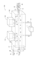
- FIG. 1 is a circuit configuration diagram of a cooling system having a manifold according to a first embodiment.
- FIG. FIG. 2 is a schematic diagram of a manifold. 3 is a cross-sectional view taken along the line III-III in FIG. 2 , illustrating an accumulator disposed in a manifold according to the first embodiment.
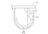
- FIG. 11 is a cross-sectional view of an accumulator disposed in a manifold according to a second embodiment. 5 is a cross-sectional view taken along the line VV in FIG. 4. 6 is a cross-sectional view taken along line VI-VI of FIG. 4.
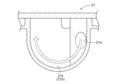
- FIG. 11 is a cross-sectional view of an accumulator disposed in a manifold according to a third embodiment.
- FIG. 8 is a cross-sectional view taken along the line VIII-VIII in FIG. 7.
- 9 is a cross-sectional view taken along line IX-IX of FIG. 7.
- FIG. 13 is a cross-sectional view of an accumulator disposed in a manifold according to a fourth embodiment.
- 11 is a cross-sectional view taken along line XI-XI of FIG. 12 is a cross-sectional view taken along line XII-XII of FIG. 10 .
- 13 is a cross-sectional view taken along line XIII-XIII of FIG. 12.
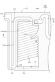
- FIG. 13 is a cross-sectional view of an accumulator disposed in a manifold according to a fifth embodiment.
- FIG. 13 is a cross-sectional perspective view of an accumulator disposed in a manifold according to a fifth embodiment.
- 16 is a cross-sectional view taken along line XVI-XVI in FIG. 14.
- 17 is a cross-sectional view taken along line XVII-XVII in FIG. 14.
- the cooling system A including the manifold 100 according to the present embodiment is roughly divided into a coolant circuit B and a refrigerant circuit C.
- a highly electrically insulating coolant such as an antifreeze mainly composed of ethylene glycol, a long-life coolant (LLC), or a fluorine-based inert liquid flows through the coolant circuit B, and a refrigerant such as a hydrofluorocarbon (HFC) or a hydrofluoroolefin (HFO) flows through the refrigerant circuit C.
- HFC hydrofluorocarbon
- HFO hydrofluoroolefin
- the manifold 100 has auxiliary equipment including a flow path housing 105, an accumulator 21 (an example of a gas-liquid separator), a chiller 110, a water-cooled condenser 120, a first electric pump 4, a rotary valve 5 consisting of a four-way valve, a second electric pump 7, a switching valve 10 consisting of a three-way valve, a third electric pump 11, a first expansion valve 23, and a second expansion valve 26.
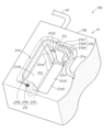
- the auxiliaries are depicted as being inside the flow path housing 105, but as shown in Fig. 2, they are actually attached to the outer surface of the flow path housing 105, except for the accumulator 21.
- the accumulator 21 is included in the flow path housing 105 and is disposed inside the flow path housing 105.
- the accumulator 21 being "disposed inside the flow path housing 105" includes the fact that at least a part of the function of the accumulator 21 is formed simultaneously when the flow path housing 105 is formed. The detailed configuration of the accumulator 21 will be described later.
- Figure 2 shows a schematic diagram of the manifold 100.
- auxiliary equipment e.g., pumps and valves
- the flow path housing 105 is formed by die casting using a metal material with high thermal conductivity, including aluminum.
- the dividing surface is not shown in Figure 2, the flow path housing 105 is formed by joining multiple housing parts.
- the flow paths and accumulator 21 that constitute the coolant circuit B and the refrigerant circuit C are formed simultaneously when the respective housing parts are molded.
- the coolant circuit B is a flow path to the right of the chiller 110 and the water-cooled condenser 120 in FIG. 1.
- the coolant circuit B has a first external flow path 31 outside the flow path housing 105.
- the first external flow path 31 is connected to a first internal flow path 41 and a second internal flow path 42 formed inside the flow path housing 105.
- the radiator 1 is disposed midway through the first external flow path 31.
- the coolant flows through the second internal flow path 42, the first external flow path 31, the radiator 1, the first external flow path 31, and the first internal flow path 41 in that order.
- the upstream side and downstream side of the flow direction of the coolant in the coolant circuit B are also simply referred to as the upstream side and downstream side.
- the second external flow path 32 and the third external flow path 33 branch off from the first external flow path 31 downstream of the radiator 1 and upstream of the first internal flow path 41.
- the second external flow path 32 is connected to the third internal flow path 43 formed inside the flow path housing 105 on the downstream side.
- the third internal flow path 43 is connected to the second internal flow path 42 on the downstream side.
- the coolant branched off from the first external flow path 31 to the second external flow path 32 flows through the second external flow path 32, cools the charger 2 and the DC-DC converter 3, and then flows into the third internal flow path 43.
- the coolant is pressurized by the first electric pump 4 in the third internal flow path 43, and then flows into the second internal flow path 42.
- a fourth internal flow path 44 branches off from the third internal flow path 43 upstream of the first electric pump 4. In the state shown in FIG. 1, the fourth internal flow path 44 is connected to the fifth internal flow path 45 via the rotary valve 5. The downstream side of the fifth internal flow path 45 is connected to the second internal flow path 42.
- the third external flow passage 33 is connected to a sixth internal flow passage 46 formed inside the flow passage housing 105 on the downstream side.
- the sixth internal flow passage 46 is connected to a seventh internal flow passage 47 via a rotary valve 5.
- the second electric pump 7 is disposed in the middle of the seventh internal flow passage 47.
- the cooling liquid branched from the first external flow passage 31 to the third external flow passage 33 flows through the third external flow passage 33, cools the power conversion module 6, and flows into the sixth internal flow passage 46. In the state shown in FIG. 1, the cooling liquid is pressurized by the second electric pump 7 in the seventh internal flow passage 47 via the rotary valve 5, and then flows out to the outside of the flow passage housing 105.
- the power conversion module 6 is a module in which a rotating electric machine, a reducer, a differential gear mechanism, and a power converter (inverter) are housed in a housing and integrated. By rotating the rotary valve 5, the fourth internal flow passage 44 and the sixth internal flow passage 46 can be connected, and the fifth internal flow passage 45 and the seventh internal flow passage 47 can be connected.
- the seventh internal flow passage 47 is connected to the fourth external flow passage 34 outside the flow passage housing 105.
- the fourth external flow passage 34 is connected to the eighth internal flow passage 48 formed inside the flow passage housing 105 on the downstream side.
- the cooling liquid flowing out of the seventh internal flow passage 47 flows through the fourth external flow passage 34, is cooled by the first heater core 8, and then cools and warms the battery 9, and flows into the eighth internal flow passage 48.
- the eighth internal flow passage 48 is connected to the chiller 110 on the downstream side.
- the downstream side of the chiller 110 is connected to the second internal flow passage 42.
- the cooling liquid flowing through the eighth internal flow passage 48 flows into the chiller 110, and is cooled in the chiller 110 by the mist-like refrigerant flowing in from the third internal refrigerant passage 73 described later, and then flows through the second internal flow passage 42.
- the cooling liquid flowing through the second internal flow passage 42 flows into the first external flow passage 31 connected to the outside of the flow passage housing 105.
- the first internal flow path 41 which is connected to the first external flow path 31, is connected to the water-cooled condenser 120 on the downstream side.
- the switching valve 10 and the third electric pump 11 are arranged in this order in the middle of the first internal flow path 41.
- the downstream side of the water-cooled condenser 120 is connected to the ninth internal flow path 49.
- the cooling liquid that flows into the first internal flow path 41 is pressurized by the third electric pump 11 and flows into the water-cooled condenser 120, where it is heated by removing heat from the refrigerant in a high-temperature compressed gas state that flows in from the second internal refrigerant path 72 (described later), and then flows through the ninth internal flow path 49 and flows out to the outside of the flow path housing 105.
- the ninth internal flow passage 49 is connected to the fifth external flow passage 35 outside the flow passage housing 105.
- the fifth external flow passage 35 is connected downstream to a tenth internal flow passage 50 formed inside the flow passage housing 105.
- the tenth internal flow passage 50 is connected downstream to the sixth internal flow passage 46.
- the coolant flowing out of the ninth internal flow passage 49 flows through the fifth external flow passage 35, is cooled by the second heater core 12, and flows into the tenth internal flow passage 50.
- the coolant flowing through the tenth internal flow passage 50 flows into the sixth internal flow passage 46.
- the switching valve 10 arranged in the first internal flow passage 41 switches the flow direction of the cooling liquid between the first internal flow passage 41 and an eleventh internal flow passage 51 formed inside the flow passage housing 105.
- the eleventh internal flow passage 51 is connected to the tenth internal flow passage 50 on the downstream side.
- the refrigerant circuit C is a flow path to the left of the chiller 110 and the water-cooled condenser 120 in FIG. 1.
- the refrigerant circuit C is formed inside the flow path housing 105, and the refrigerant flows through it.
- the refrigerant circuit C has a first internal refrigerant passage 71 (an example of a refrigerant passage) on the downstream side of the flow direction of the refrigerant relative to the chiller 110 (hereinafter, the upstream side and downstream side of the flow direction of the refrigerant in the refrigerant circuit C are simply referred to as the upstream side and downstream side).
- the first internal refrigerant passage 71 is connected to the accumulator 21 formed inside the flow path housing 105.
- the accumulator 21 is connected to the first external refrigerant passage 61 formed outside the flow path housing 105 (see also FIG. 2).
- the compressor 22 is disposed in the middle of the first external refrigerant passage 61.
- the first external refrigerant passage 61 is connected to the second internal refrigerant passage 72 formed inside the flow path housing 105 on the downstream side.
- the second internal refrigerant passage 72 is connected to the water-cooled condenser 120 on the downstream side.
- the downstream side of the water-cooled condenser 120 is connected to a third internal refrigerant passage 73 formed inside the flow path housing 105.
- the third internal refrigerant passage 73 is connected to the chiller 110 via a first expansion valve 23 arranged midway.
- the water-cooled condenser 120 is installed at a position on the upstream side of the flow direction of the refrigerant in the third internal refrigerant passage 73
- the chiller 110 is installed at a position on the downstream side of the flow direction of the refrigerant.
- a fourth internal refrigerant path 74 branches off from the third internal refrigerant path 73 upstream of the first expansion valve 23 in the third internal refrigerant path 73.
- a second expansion valve 26 is arranged in the middle of the fourth internal refrigerant path 74.
- the fourth internal refrigerant path 74 is connected to a second external refrigerant path 62 formed outside the flow path housing 105.
- An evaporator 24 and a check valve 25 are arranged in this order in the middle of the second external refrigerant path 62.
- the second external refrigerant path 62 is connected to a fifth internal refrigerant path 75 formed inside the flow path housing 105.
- the fifth internal refrigerant path 75 is connected to the first internal refrigerant path 71 on the downstream side.
- the refrigerant that flows through the first external refrigerant passage 61 and becomes a high-temperature compressed gas in the compressor 22 flows through the first external refrigerant passage 61 and flows through the second internal refrigerant passage 72 into the water-cooled condenser 120.
- the refrigerant is condensed and liquefied in the water-cooled condenser 120 by the cooling liquid that flows in from the first internal flow path 41 taking heat from it.
- the liquefied refrigerant used for cooling the interior of the vehicle leaves the water-cooled condenser 120 and flows through the third internal refrigerant passage 73 to the fourth internal refrigerant passage 74, is expanded by the second expansion valve 26 to become a low-temperature, low-pressure mist, then flows out of the flow path housing 105, flows through the second external refrigerant passage 62, and is sent to the evaporator 24.
- the mist-like refrigerant takes heat from the air introduced from the outside in the evaporator 24 and evaporates. Conversely, the air is cooled by the refrigerant taking heat from it, and is sent into the vehicle as cold air.
- the evaporated refrigerant flows through the check valve 25 arranged in the second external refrigerant passage 62 into the fifth internal refrigerant passage 75 and is sent from the first internal refrigerant passage 71 to the accumulator 21.
- the evaporated refrigerant an example of a gas refrigerant; hereinafter also simply referred to as a gas refrigerant
- a liquid refrigerant an example of a liquid refrigerant; hereinafter also referred to as a liquid refrigerant 27 (see FIG. 3)
- the liquid refrigerant 27 is separated from the gas refrigerant.
- the gas refrigerant then flows out of the accumulator 21, circulates through the first external refrigerant passage 61, and returns to the compressor 22, where it is compressed again to become a high-temperature compressed gas.
- the mist refrigerant absorbs heat from the cooling liquid flowing in from the eighth internal flow passage 48 in the chiller 110 and evaporates.
- the evaporated gaseous refrigerant is sent to the accumulator 21 through the first internal refrigerant passage 71.
- the second external refrigerant passage 62 has a check valve 25, so the gaseous refrigerant flowing out of the chiller 110 does not flow into the evaporator 24.
- the accumulator 21 if the gaseous refrigerant contains liquid, the liquid refrigerant is separated. The evaporated refrigerant then flows out of the accumulator 21, flows through the first external refrigerant passage 61, and returns to the compressor 22, where it is compressed again to become a high-temperature compressed gas.
- the flow paths connected to the chiller 110 are arranged in the flow path housing 105 such that the eighth internal flow path 48 of the cooling liquid circuit B flowing into the chiller 110 and the first internal refrigerant path 71 of the refrigerant circuit C flowing out of the chiller 110 are arranged parallel and close to each other, and the second internal flow path 42 of the cooling liquid circuit B flowing out of the chiller 110 and the third internal refrigerant path 73 of the refrigerant circuit C flowing into the chiller 110 are arranged parallel and close to each other.
- the flow direction of the cooling liquid flowing through the eighth internal flow path 48 is opposite to the flow direction of the refrigerant flowing through the first internal refrigerant path 71
- the flow direction of the cooling liquid flowing through the second internal flow path 42 is opposite to the flow direction of the refrigerant flowing through the third internal refrigerant path 73.
- the eighth internal flow path 48 and the first internal refrigerant path 71 exchange heat at a location formed in an L-shape
- the second internal flow path 42 and the third internal refrigerant path 73 exchange heat at a location formed in a straight line.
- heat exchange occurs not only in the chiller 110, but also between the cooling liquid flowing through the eighth internal flow path 48 and the refrigerant flowing through the first internal refrigerant path 71, and also between the cooling liquid flowing through the second internal flow path 42 and the refrigerant flowing through the third internal refrigerant path 73. In this way, heat exchange also occurs between the internal flow path outside the chiller 110 and the internal refrigerant path, so that sufficient cooling performance can be obtained even if a small chiller 110 is used.
- the flow paths connected to the water-cooled condenser 120 are arranged in parallel and close proximity to the first internal flow path 41 of the cooling liquid circuit B flowing into the water-cooled condenser 120 and the third internal refrigerant path 73 of the refrigerant circuit C flowing out of the water-cooled condenser 120, and the ninth internal flow path 49 of the cooling liquid circuit B flowing out of the water-cooled condenser 120 and the second internal refrigerant path 72 of the refrigerant circuit C flowing into the water-cooled condenser 120.
- the flow direction of the cooling liquid flowing through the first internal flow path 41 is opposite to the flow direction of the refrigerant flowing through the third internal refrigerant path 73
- the flow direction of the cooling liquid flowing through the ninth internal flow path 49 is opposite to the flow direction of the refrigerant flowing through the second internal refrigerant path 72.
- the first internal flow path 41 and the third internal refrigerant path 73 exchange heat at a point formed in a straight line
- the ninth internal flow path 49 and the second internal refrigerant path 72 exchange heat at a point formed in an L-shape.
- heat exchange occurs not only in the water-cooled condenser 120, but also between the cooling liquid flowing through the first internal flow path 41 and the refrigerant flowing through the third internal refrigerant path 73, and between the cooling liquid flowing through the ninth internal flow path 49 and the refrigerant flowing through the second internal refrigerant path 72.
- heat exchange also occurs between the internal flow path outside the water-cooled condenser 120 and the internal refrigerant path, so that sufficient cooling performance can be obtained even if a small water-cooled condenser 120 is used.
- an accumulator 21 is disposed inside the flow path housing 105 of the manifold 100 according to this embodiment. Specifically, as shown in Fig. 3, a flow path having a gas-liquid separation function is formed inside the flow path housing 105.
- the upward direction along the paper surface will be referred to as the upward direction of the accumulator 21, and the downward direction will be referred to as the downward direction of the accumulator 21.
- the direction from the upward direction to the downward direction of the accumulator 21 will be referred to as the vertical direction.
- a gas refrigerant flows through the first internal refrigerant passage 71 formed in the flow path housing 105.
- the gas refrigerant flows from the first internal refrigerant passage 71 into the inlet portion 21a of the accumulator 21.
- the downstream end of the first internal refrigerant passage 71 (the upstream end of the inlet portion 21a) is disposed near the center in the up-down direction of the flow path housing 105.
- the inlet portion 21a is a flow path through which the gas refrigerant flows, which is disposed between the first internal refrigerant passage 71 and a gas-liquid separation portion 21b of the accumulator 21 described later.
- the inlet 21a of the accumulator 21 curves upward from the point where it is connected to the first internal refrigerant passage 71, and is folded back 180 degrees downward near the upper end of the flow path housing 105.
- the folded back inlet 21a extending downward is connected to the gas-liquid separation section 21b at its downstream end.
- the gas-liquid separation section 21b is a flow path for the gas refrigerant that has the function of separating the liquid refrigerant 27 contained in the gas refrigerant from the gas refrigerant.
- the gas-liquid separation section 21b has a U-shape that extends downward from the top of the flow path housing 105, is folded back 180 degrees at the bottom end, and extends upward.
- the flow path cross-sectional area of the gas-liquid separation section 21b is larger than the flow path cross-sectional area of the inlet 21a.
- the gas refrigerant flowing into the accumulator 21 contains mist-like refrigerant oil in addition to liquid refrigerant 27.
- the refrigerant oil is a lubricant that lubricates the compressor 22.
- the refrigerant oil flows out of the compressor 22 in mist-like form and is included in the gas refrigerant, and is returned to the compressor 22 together with the gas refrigerant.
- the mist-like refrigerant oil is separated from the gas refrigerant together with the liquid refrigerant 27 in the gas-liquid separation section 21b.
- the liquid refrigerant 27 and the refrigerant oil may be collectively referred to as liquid refrigerant 27, etc.
- the downstream end of the gas-liquid separation section 21b is located at the upper end of the flow path housing 105.
- the downstream end of the gas-liquid separation section 21b is connected to the extension section 21d arranged on the opposite side of the inlet section 21a with respect to the gas-liquid separation section 21b.
- the extension section 21d is a flow path through which the gas refrigerant flows after the liquid refrigerant 27 and the like are separated, and extends downward from the upper part of the flow path housing 105, turns 180 degrees at the lower end, and extends upward. That is, from the downstream end of the gas-liquid separation section 21b to the upstream end of the extension section 21d, the flow path turns 180 degrees, and the extension section 21d has a U-shape.
- the upstream end and downstream end of the extension section 21d are connected by the through passage 21j, which is a through hole.
- the flow path cross-sectional area of the extension section 21d is smaller than the flow path cross-sectional area of the gas-liquid separation section 21b.
- the outflow section 21e is arranged from the downstream end of the extension section 21d toward the side.
- the outflow section 21e is connected to the extension section 21d, and the gas refrigerant that has flowed through the extension section 21d flows through it.
- the extension section 21d communicates with the gas-liquid separation section 21b and the outflow section 21e.
- the outflow section 21e is located at the upper end of the flow path housing 105 and is connected to the first external refrigerant passage 61 (see FIG. 2), and the gas refrigerant that has flowed through the outflow section 21e flows into the first external refrigerant passage 61.
- the outflow section 21e is a flow path that causes the gas refrigerant that has been separated from the liquid refrigerant 27, etc., to flow out of the accumulator 21.
- the flow path cross-sectional area of the outflow section 21e is smaller than the flow path cross-sectional area of the gas-liquid separation section 21b.
- the liquid refrigerant 27 etc. separated from the gas refrigerant in the gas-liquid separation section 21b is stored in a first storage section 21c (an example of a storage section) which is the bottom part of the U-shape of the gas-liquid separation section 21b.
- the first storage section 21c and the vicinity of the lower end of the extension section 21d are connected by a communication section 21f which extends laterally from the first storage section 21c.
- the gas refrigerant that flows into the inlet section 21a from the first internal refrigerant passage 71 flows through the inlet section 21a and into the gas-liquid separation section 21b, and flows downward through the U-shaped gas-liquid separation section 21b.
- the flow direction of the gas refrigerant is changed 180 degrees from downward to upward at the lower end (bottom) of the U-shape. In this way, when the gas refrigerant changes its flow direction, liquid refrigerant 27 and the like are separated from the gas refrigerant.
- the separated liquid refrigerant 27 and the like are stored in the first storage section 21c.
- the gas refrigerant from which the liquid refrigerant 27 and the like has been separated flows upward through the gas-liquid separation section 21b, is turned back 180 degrees, and flows into the extension section 21d.
- the upstream end and downstream end of the extension portion 21d are connected by the through passage 21j, so the gas refrigerant that flows into the extension portion 21d is divided into the extension portion 21d and the through passage 21j and flows there, and then merges at the downstream end of the extension portion 21d.
- the merged gas refrigerant flows into the outflow portion 21e and flows out from the outflow portion 21e to the first external refrigerant passage 61 connected to the outside of the accumulator 21.
- the first storage section 21c Since the first storage section 21c is connected to the extension section 21d via the communication section 21f, negative pressure is generated between the first storage section 21c and the communication section 21f by the gas refrigerant flowing through the extension section 21d. Therefore, when the gas refrigerant passes through the lower end of the extension section 21d, some of the liquid refrigerant 27 etc. stored in the first storage section 21c is sucked into the gas refrigerant by the negative pressure, flows through the communication section 21f, and is again included in the gas refrigerant flowing through the extension section 21d. The gas refrigerant containing the liquid refrigerant 27 etc. flows upward through the extension section 21d.
- the gas refrigerant that has flowed through the through passage 21j merges with the gas refrigerant that has flowed through the through passage 21j at the downstream end of the extension section 21d.
- the gas refrigerant that has flowed through the through passage 21j does not contain the liquid refrigerant 27 etc. Therefore, the gas refrigerant after merging at the downstream end of the extension section 21d contains only a small amount of liquid refrigerant 27 etc.
- the gas refrigerant that has joined at the downstream end of the extension portion 21d then flows through the outflow portion 21e and flows out of the accumulator 21.
- the latter amount of liquid refrigerant 27, etc. is significantly smaller. If a gas refrigerant containing a large amount of liquid refrigerant 27 flows into the compressor 22, liquid compression may occur in the compressor 22, which may damage the compressor 22. However, by making the amount of liquid refrigerant 27 contained in the gas refrigerant in the accumulator 21 small, even if a gas refrigerant containing a small amount of liquid refrigerant 27 flows out of the accumulator 21 and flows into the compressor 22, the compressor 22 will not be liquid compressed, so there is no risk of the compressor 22 being damaged.
- the compressor 22 also compresses the liquid refrigerant 27 contained in the gas refrigerant to produce a high-temperature compressed gas refrigerant, so there is no risk of a shortage of gas refrigerant causing a decrease in the cooling performance inside the vehicle.
- the refrigeration oil is returned to the compressor 22, it is used again as a lubricant.
- the liquid refrigerant 27 etc. stored in the first storage section 21c may exceed a predetermined storage amount (the liquid level may reach the communication section 21f).
- the excess liquid refrigerant 27 etc. flows through the communication section 21f and is stored in the second storage section 21i located at the lower end of the extension section 21d.
- the second storage section 21i is the bottom part of the U-shape of the extension section 21d.
- the manifold 100 can be made smaller and less expensive than when the accumulator 21 is attached externally.
- the accumulator 21 disposed inside the manifold 100 according to the second embodiment will be described with reference to Figures 4 to 6.
- the shape of the downstream end of the inlet portion 21a in the accumulator 21 and the configuration of the gas-liquid separation portion 21b are different from those of the accumulator 21 of the first embodiment.
- the accumulator 21 has the same configuration as the first embodiment. Therefore, in the description of this embodiment, the same reference numerals are used for parts having the same configuration as the first embodiment, and detailed description of the same configuration will be omitted.
- the downstream end of the inlet section 21a of the accumulator 21 in the first embodiment extends downward and is connected to the gas-liquid separation section 21b, but the downstream end of the inlet section 21a in this embodiment extends horizontally (perpendicular to the vertical direction) and is connected to the gas-liquid separation section 21b as shown in Figures 4 and 5.
- the gas-liquid separation section 21b has an inner circumferential surface 21k that is arc-shaped when viewed in the vertical direction.
- the downstream end of the inlet section 21a is disposed to the side of the upstream end of the gas-liquid separation section 21b and is connected to the gas-liquid separation section 21b.
- the downstream end of the inlet section 21a is connected to the gas-liquid separation section 21b along the tangential direction of the inner circumferential surface 21k of the gas-liquid separation section 21b.
- the gas refrigerant that flows through the inlet section 21a and into the gas-liquid separation section 21b flows along the arc-shaped inner circumferential surface 21k and becomes a horizontal swirling flow within the gas-liquid separation section 21b.
- the liquid refrigerant 27, etc. contained in the gas refrigerant is separated from the gas refrigerant by the centrifugal force of the swirling flow and adheres to the inner circumferential surface 21k.
- the liquid refrigerant 27, etc. that adheres to the inner circumferential surface 21k falls downward along the inner circumferential surface 21k due to gravity and is stored in the first storage section 21c.
- the gas refrigerant from which the liquid refrigerant 27, etc. has been separated flows upward through the gas-liquid separation section 21b, turns around 180 degrees and flows into the extension section 21d.
- the accumulator 21 disposed inside the manifold 100 according to the third embodiment will be described with reference to Figures 7 to 9.
- the shape of the downstream end of the inlet portion 21a in the accumulator 21 and the configuration of the gas-liquid separation portion 21b are different from those of the accumulator 21 in the first and second embodiments.
- the accumulator 21 has the same configuration as the first and second embodiments. Therefore, in the description of this embodiment, the same reference numerals are used for parts having the same configuration as the first and second embodiments, and detailed description of the same configuration will be omitted.
- the downstream end of the inlet section 21a extends obliquely downward (diagonally downward inclined with respect to the vertical direction) and is connected to the gas-liquid separation section 21b, as shown in Figures 7 and 8.
- the gas-liquid separation section 21b has an inner circumferential surface 21k that is arc-shaped when viewed in the vertical direction.
- the downstream end of the inlet section 21a is disposed to the side of the upstream end of the gas-liquid separation section 21b and is connected to the gas-liquid separation section 21b.
- the downstream end of the inlet section 21a is connected to the gas-liquid separation section 21b along the tangent direction of the inner circumferential surface 21k of the gas-liquid separation section 21b.
- gas-liquid separation section 21b has a curved guide 21m below the downstream end of inlet section 21a and below inner surface 21k.
- the curved surface of guide 21m is curved so that the base end side is vertical and the tip side is horizontal. Therefore, the gas refrigerant that flows diagonally downward through inlet section 21a and flows diagonally into gas-liquid separation section 21b has its flow direction changed to horizontal by guide 21m, and becomes a horizontal swirling flow within gas-liquid separation section 21b due to the arc-shaped inner surface 21k.
- Liquid refrigerant 27 etc. contained in the gas refrigerant is separated from the gas refrigerant by the centrifugal force caused by the swirling flow and adheres to inner surface 21k and guide 21m.
- the liquid refrigerant 27 and other liquids adhering to the inner circumferential surface 21k and the guide 21m fall downward along the inner circumferential surface 21k due to gravity, and also fall downward from the tip of the guide 21m, and are stored in the first storage section 21c.
- the gas refrigerant from which the liquid refrigerant 27 and other liquids have been separated flows upward through the gas-liquid separation section 21b, turns around 180 degrees, and flows into the extension section 21d.
- the accumulator 21 disposed inside the manifold 100 according to the fourth embodiment will be described with reference to Figures 10 to 13.
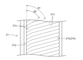
- This embodiment differs from the third embodiment in that a plurality of grooves 21n are formed extending along the arc-shaped inner circumferential surface 21k of the accumulator 21, and that the length of the guide 21m is shortened.
- the configuration is the same as that of the third embodiment. Therefore, in the description of this embodiment, the same reference numerals are used for the parts having the same configuration as the third embodiment, and detailed description of the same configuration is omitted.
- the multiple grooves 21n are provided to efficiently guide the liquid refrigerant 27, which is separated from the gas refrigerant that flows into the gas-liquid separation section 21b along the guide 21m by the centrifugal force of the swirling flow and adheres to the inner circumferential surface 21k, to the first storage section 21c.
- the multiple grooves 21n have a first angle ⁇ 1 inclined with respect to the vertical direction, and are all formed to be parallel (see FIG. 13).
- the first angle ⁇ 1 of the grooves 21n is an angle parallel to the tangent direction of the tip of the guide 21m, whose tip is inclined with respect to the vertical direction due to its shortened length.
- the cross section perpendicular to the extension direction of the multiple grooves 21n is arc-shaped.
- the groove end 21o which is the downstream end of each of the multiple grooves 21n, does not contact the plane 21p (see FIG. 12) that constitutes the gas-liquid separation section 21b.
- the groove end 21o has a second angle ⁇ 2 that is closer to vertical than the first angle ⁇ 1 of the groove 21n upstream from it.
- the liquid refrigerant 27, etc. that flows diagonally downward through the groove 21n flows diagonally downward through the groove end 21o at an angle steeper than the first angle ⁇ 1 and is stored in the first storage section 21c.
- the gas refrigerant that flows through the inlet 21a and enters the gas-liquid separation section 21b at an angle is changed by the guide 21m to a direction along the first angle ⁇ 1, and the arc-shaped inner circumferential surface 21k causes a swirling flow in the gas-liquid separation section 21b along the first angle ⁇ 1.
- Liquid refrigerant 27, etc. contained in the gas refrigerant is separated from the gas refrigerant by the centrifugal force of the swirling flow and adheres to the inner circumferential surface 21k and the guide 21m. Since the inner circumferential surface 21k has a plurality of grooves 21n formed therein, the liquid refrigerant 27, etc.
- a plurality of grooves 21n inclined at a first angle ⁇ 1 are formed on the inner surface 21k of the gas-liquid separation section 21b, so that the liquid refrigerant 27, etc., separated from the gas refrigerant by centrifugal force can flow along the grooves 21n.
- the liquid refrigerant 27, etc. flows only within the grooves 21n, and the cross section perpendicular to the extension direction of the grooves 21n is arc-shaped, so that the small droplets of the liquid refrigerant 27, etc., separated from the gas refrigerant and attached to the inner surface 21k, can be easily collected in the grooves 21n to form large droplets.
- the liquid refrigerant 27, etc. becomes a large droplet, the liquid refrigerant 27, etc., can easily flow through the grooves 21n toward the groove ends 21o due to their weight. Furthermore, since the groove ends 21o of the grooves 21n are inclined at a second angle ⁇ 2, which is closer to vertical than the first angle ⁇ 1, the liquid refrigerant 27, etc. can be easily discharged from the groove ends 21o. This allows the liquid refrigerant 27, etc., separated from the gas refrigerant, to be efficiently stored in the first storage section 21c, and the separated liquid refrigerant 27, etc., to be efficiently recovered.
- the accumulator 21 disposed inside the manifold 100 according to the fifth embodiment will be described with reference to Figures 14 to 17.
- This embodiment differs from the above-described embodiments in that the gas-liquid separation section 21b of the accumulator 21 includes a wall-shaped separation wall 21b3, and in that the arrangement of the outflow section 21e connected to the first external refrigerant passage 61 is different.
- this embodiment has the same configuration as the above-described embodiments. Therefore, in the description of this embodiment, the same reference numerals are used for parts having the same configuration as the above-described embodiments, and detailed description of the same configuration will be omitted.
- an accumulator 21 is formed inside. Specifically, as shown in FIG. 14, a flow path having a gas-liquid separation function is formed inside the flow path housing 105.
- the accumulator 21 is configured to have an inlet portion 21a, a gas-liquid separation portion 21b, a first storage portion 21c, an extension portion 21d, and an outlet portion 21e.
- the upward direction along the paper surface is referred to as the upper side of the accumulator 21, and the downward direction is referred to as the lower side of the accumulator 21.
- the direction from the upper side to the lower side of the accumulator 21 is referred to as the vertical direction.
- a gas refrigerant flows through the first internal refrigerant passage 71 (see FIG. 2) formed in the flow path housing 105.
- the gas refrigerant flows from the first internal refrigerant passage 71 into the inlet section 21a of the accumulator 21.
- the downstream end of the first internal refrigerant passage 71 (the upstream end of the inlet section 21a) is located near the center of the flow path housing 105 in the vertical direction.
- the inlet section 21a is a flow path through which the gas refrigerant flows, located between the first internal refrigerant passage 71 and the gas-liquid separation section 21b of the accumulator 21 described below.
- the inlet 21a of the accumulator 21 curves and extends upward from the point where it is connected to the first internal refrigerant passage 71, and then curves further upward and extends horizontally.
- the horizontal extension end (downstream end) of the inlet 21a is connected to the gas-liquid separation section 21b.
- the gas-liquid separation section 21b has the function of separating the liquid refrigerant 27 and the like contained in the gas refrigerant from the gas refrigerant.
- the gas-liquid separation section 21b has a guide space 21b1, a through hole 21b2, a separation wall 21b3, and a guide refrigerant path 21b4.
- the guide space 21b1 is a space for guiding the gas refrigerant flowing through the inlet section 21a to the through hole 21b2.
- the guide space 21b1 is connected to the downstream end of the inlet section 21a, and is a rectangular parallelepiped space extending from the downstream end of the inlet section 21a toward the back of the paper.
- the direction toward the back of the paper is referred to as the depth direction.
- the guide space 21b1 is connected to the guide refrigerant path 21b4 via the through hole 21b2.
- the guide refrigerant path 21b4 is formed inside the inlet section 21a.
- Through hole 21b2 is a hole formed downward from the vertically lower surface of the six surfaces that define guide space 21b1.
- the inner diameter (flow path cross-sectional area) of through hole 21b2 is smaller than the area of the vertically lower surface that defines guide space 21b1. Therefore, the flow speed of the gas refrigerant flowing through through hole 21b2 is faster than the flow speed of the gas refrigerant flowing through inlet portion 21a. This causes the gas refrigerant to collide at high speed with separation wall 21b3 (described later), separating liquid refrigerant 27, etc. from the gas refrigerant.
- the through hole 21b2 is connected to the guide refrigerant passage 21b4 formed to be parallel to the inlet portion 21a. That is, the guide refrigerant passage 21b4 extends horizontally from the upstream end, then curves and extends vertically downward.
- the downstream end of the guide refrigerant passage 21b4 is connected to the first storage portion 21c. That is, the downstream end of the guide refrigerant passage 21b4 is the downstream end of the gas-liquid separation portion 21b.
- the length of the guide refrigerant passage 21b4 in the depth direction is longer than the length of the inlet portion 21a in the depth direction (see FIG. 16).
- the lower wall is the separation wall 21b3.
- the separation wall 21b3 is formed to extend horizontally, then curve and extend vertically downward, similar to the guide refrigerant passage 21b4.
- the downstream end of the gas-liquid separation section 21b is located above the flow path housing 105, and is connected to the first storage section 21c through the inlet 21c1.
- the inlet 21c1 is the boundary between the gas-liquid separation section 21b and the first storage section 21c.
- the first storage section 21c is a space in which the liquid refrigerant 27, etc., separated from the gas refrigerant in the gas-liquid separation section 21b is stored.
- a desiccant 21c3 made of zeolite or the like that absorbs excess moisture mixed into the refrigerant circuit C is disposed in the first storage section 21c.
- the outlet 21c2 is the boundary between the first storage section 21c and the extension section 21d.
- the inlet 21c1 and the outlet 21c2 are arranged at a distance from each other in opposing both side regions of the inner surface 21c5 that forms the first storage section 21c when viewed in the vertical direction.
- a protruding wall 21c4 an example of an outflow suppression section
- the protruding wall 21c4 is a wall that protrudes in a convex shape from the inner surface 21c5 of the first storage section 21c toward the horizontal inside.
- a communication section 21f is formed near the bottom of the first storage section 21c, connecting the first storage section 21c to the lower end of the extension section 21d.
- the communication section 21f is formed along the horizontal direction as shown in Figures 14, 15, and 17.
- the communication section 21f has a large diameter section 21f1 connected to the first storage section 21c, and a small diameter section 21f2 that connects the large diameter section 21f1 and the extension section 21d and has a smaller inner diameter than the large diameter section 21f1.
- the large diameter section 21f1 is formed in a V-shape when viewed in the vertical direction.
- the small diameter section 21f2 is an orifice, and is formed by bending 90 degrees with respect to the large diameter section 21f1.
- a strainer 21f3 is arranged at the downstream end of the large diameter section 21f1 (at the boundary with the small diameter section 21f2) to remove foreign matter contained in the liquid refrigerant 27, etc.
- the extension portion 21d which is connected to the outlet 21c2, which is the downstream end of the first storage portion 21c, is a flow path through which the gas refrigerant flows after the liquid refrigerant 27 and other components are separated in the gas-liquid separation portion 21b.
- the extension portion 21d extends horizontally above the flow path housing 105, then curves and extends downward, bends 180 degrees at the bottom end, extends upward, and then curves again to extend horizontally.
- extension portion 21d As described above, the lower end of extension portion 21d (where it is folded back 180 degrees) is connected to small diameter portion 21f2 of communication portion 21f. Furthermore, the upstream end and downstream end of extension portion 21d overlap when viewed vertically and are connected by through passage 21j, which is a through hole.
- the upstream end and downstream end of extension portion 21d and through passage 21j are provided in the central region of inner surface 21c5, and are provided above outlet 21c2 of first storage portion 21c.
- the outflow portion 21e is disposed from the downstream end of the extension portion 21d toward the upper side.
- the outflow portion 21e is connected to the extension portion 21d, and the gas refrigerant that has flowed through the extension portion 21d flows through it.
- the extension portion 21d is a flow path that connects the first storage portion 21c and the outflow portion 21e, and the flow direction of the gas refrigerant is changed by 90 degrees from the extension portion 21d to the outflow portion 21e.
- the outflow portion 21e is located at the upper end of the flow path housing 105 and is connected to the first external refrigerant passage 61, and the gas refrigerant that has flowed through the outflow portion 21e flows into the first external refrigerant passage 61.
- the outflow portion 21e is a flow path that flows the gas refrigerant after separation of the liquid refrigerant 27, etc., to the outside of the accumulator 21.
- the guide space 21b1 is connected to the through hole 21b2, and converts the flow direction of the gas refrigerant that flows horizontally to the vertical direction. Since the flow path cross-sectional area of the through hole 21b2 is smaller than the area of the vertically lower surface among the surfaces that define the guide space 21b1, the gas refrigerant flowing through the through hole 21b2 flows at a higher flow rate than when it flows through the inlet 21a.
- the gas refrigerant that passes through the through hole 21b2 collides with the separation wall 21b3 at a high speed, and this collision separates the liquid refrigerant 27 and the like from the gas refrigerant.
- the gas refrigerant from which the liquid refrigerant 27 etc. has been separated turns horizontally and flows through the guide refrigerant passage 21b4, and flows into the first storage section 21c from the inlet 21c1.
- the gas refrigerant that flows into the first storage section 21c flows upward and flows into the extension section 21d from the outlet 21c2.
- the upstream and downstream ends of the extension section 21d are connected by the through passage 21j, so that a portion of the gas refrigerant that flows from the first storage section 21c into the extension section 21d flows through the through passage 21j and merges with the gas refrigerant that has flowed through the extension section 21d at the downstream end of the extension section 21d.
- the upstream and downstream ends of the extension portion 21d are connected by the through passage 21j, so that the pressure of the gas refrigerant flowing through the extension portion 21d can be kept constant.
- the merged gas refrigerant flows into the outflow portion 21e and flows out from the outflow portion 21e into the first external refrigerant passage 61 connected to the outside of the accumulator 21.
- the first storage section 21c is provided with a desiccant 21c3. This desiccant 21c3 absorbs excess moisture that has entered the refrigerant circuit C, preventing freezing in the first expansion valve 23, second expansion valve 26, etc.
- the inlet 21c1 and the outlet 21c2 are arranged at a distance from each other in opposing side regions of the inner surface 21c5 that forms the first storage portion 21c when viewed in the vertical direction. In this manner, when the inlet 21c1 and the outlet 21c2 are arranged at a distance from each other, it is possible to suppress the problem that the liquid refrigerant 27, etc. that flows from the inlet 21c1 into the first storage portion 21c flows out from the outlet 21c2 and circulates through the extension portion 21d without being stored in the first storage portion 21c.
- a protruding wall 21c4 is arranged, which is formed to protrude horizontally inward from the inner surface 21c5 of the first storage portion 21c in a convex shape.
- the first storage section 21c Since the first storage section 21c is connected to the extension section 21d via the communication section 21f, negative pressure is generated between the first storage section 21c and the communication section 21f by the gas refrigerant flowing through the extension section 21d. Therefore, when the gas refrigerant passes through the lower end of the extension section 21d, some of the liquid refrigerant 27, etc. stored in the first storage section 21c is sucked into the gas refrigerant by the negative pressure and flows through the communication section 21f, and is again included in the gas refrigerant flowing through the extension section 21d. At this time, foreign matter contained in the liquid refrigerant 27, etc. is captured by the strainer 21f3 and does not flow into the extension section 21d.
- the inner diameter of the small diameter section 21f2 is very small compared to the large diameter section 21f1, so only a small amount of the liquid refrigerant 27, etc. is again included in the gas refrigerant flowing through the extension section 21d.
- the gas refrigerant containing the liquid refrigerant 27, etc. at the lower end of the extension portion 21d flows upward through the extension portion 21d.
- the flow direction of the gas refrigerant changes by 90 degrees at the downstream end of the extension portion 21d and flows through the outflow portion 21e.
- some of the liquid refrigerant 27, etc. contained in the gas refrigerant does not follow the gas refrigerant and adheres to the wall at the downstream end of the extension portion 21d.
- the through passage 21j is provided above the outlet 21c2 of the first storage portion 21c, the liquid refrigerant 27, etc. that adheres to the wall is returned to the first storage portion 21c through the through passage 21j. This prevents the liquid refrigerant 27, etc. from flowing out of the accumulator 21 excessively.
- the manifold 100 can be made smaller and less expensive than when the accumulator 21 is attached externally.
- the gas-liquid separation section 21b of the accumulator 21 has a U-shape, but is not limited thereto.
- the gas-liquid separation section 21b may have any shape as long as the liquid refrigerant 27 and the like can be separated from the gas refrigerant.
- a plate-shaped section that causes the liquid refrigerant 27 and the like to collide with each other to separate the liquid refrigerant 27 and the like may be provided in the gas-liquid separation section 21b.
- multiple grooves 21n are formed on the inner circumferential surface 21k to form the fourth embodiment, but this is not limited to this. In the configuration of the second embodiment, multiple grooves 21n may be formed on the inner circumferential surface 21k.
- the cross section of the groove 21n is arc-shaped, but this is not limited to this.
- the cross section of the groove may be triangular, and any shape can be applied as long as it can effectively guide the separated liquid refrigerant 27, etc., to the first storage section 21c.
- the gas refrigerant is collided vertically against the horizontally extending separation wall 21b3, but this is not limited to the above.
- the separation wall 21b3 may be inclined toward the first storage section 21c. If the separation wall 21b3 is inclined, the separated liquid refrigerant 27, etc. is more likely to be guided to the first storage section 21c.
- the separation wall 21b3 may extend vertically, and the gas refrigerant may be collided horizontally. If the separation wall 21b3 extends vertically, the liquid refrigerant 27, etc. separated by the collision of the gas refrigerant falls along the separation wall 21b3, making it easier to store the liquid refrigerant 27, etc. in the first storage section 21c.
- the large diameter portion 21f1 of the communication portion 21f is formed in a V-shape when viewed vertically, but the large diameter portion 21f1 may be linear. Also, the small diameter portion 21f2 is bent 90 degrees relative to the large diameter portion 21f1, but the large diameter portion 21f1 and the small diameter portion 21f2 may be linearly arranged.
- a strainer 21f3 is disposed in the communication portion 21f to remove foreign matter contained in the liquid refrigerant 27, etc. However, if the foreign matter contained in the liquid refrigerant 27, etc. does not adversely affect the operation of the refrigerant circuit C, the strainer 21f3 may be omitted.
- One embodiment of the manifold (100) includes a flow path housing (105) having a refrigerant flow path (71) through which a refrigerant flows, and the flow path housing (105) includes an internal gas-liquid separator (21) that separates liquid refrigerant (27), which is a liquid refrigerant contained in the gas refrigerant, from the gas refrigerant, which is a gas refrigerant, which flows through the refrigerant flow path (71).
- the manifold (100) of this embodiment includes an auxiliary device, the gas-liquid separator (21), inside the flow path housing (105), making it possible to make the manifold (100) smaller and less expensive than when the gas-liquid separator (21) is attached externally.
- the gas-liquid separator (21) includes an inlet section (21a) into which the gas refrigerant flows, a gas-liquid separation section (21b) that separates the liquid refrigerant (27) from the gas refrigerant that flows into the inlet section (21a), a storage section (21c) that stores the liquid refrigerant (27) separated in the gas-liquid separation section (21b), an outlet section (21e) from which the gas refrigerant flows out after the liquid refrigerant (27) is separated, and an extension section (21d) that connects the gas-liquid separation section (21b) and the outlet section (21e).
- the gas-liquid separator (21) includes an inlet section (21a) into which the gas refrigerant flows, a gas-liquid separation section (21b) that separates the liquid refrigerant (27) from the gas refrigerant that flows into the inlet section (21a), a storage section (21c) that stores the liquid refrigerant (27) separated in the gas-liquid separation section (21b), an outlet section (21e) from which the gas refrigerant flows out after the liquid refrigerant (27) is separated, and an extension section (21d) that connects the gas-liquid separation section (21b) and the outlet section (21e).
- the gas refrigerant that flows into the inlet section (21a) of the gas-liquid separator (21) flows through the extension section (21d) and flows out from the outlet section (21e) after the liquid refrigerant (27) is efficiently separated in the gas-liquid separation section (21b). Meanwhile, the liquid refrigerant (27) separated in the gas-liquid separation section (21b) can be stored in the storage section (21c).
- the gas-liquid separator (21) further includes a through passage (21j) that connects the upstream end and downstream end of the extension portion (21d).
- the flow path cross-sectional area of the gas-liquid separation section (21b) is larger than the flow path cross-sectional areas of the inlet section (21a) and the outlet section (21e)
- the downstream end of the inlet section (21a) is disposed above the upstream end of the gas-liquid separation section (21b) and communicates with the gas-liquid separation section (21b)
- the extension section (21d) is folded back from the downstream end of the gas-liquid separation section (21b) and extends downward
- the outlet section (21e) is disposed to the side of the downstream end of the extension section (21d)
- the gas refrigerant preferably flows downward from the inlet section (21a) into the gas-liquid separation section (21b) and flows out laterally from the outlet section (21e).
- the flow path cross-sectional area of the gas-liquid separation section (21b) of the gas-liquid separator (21) is larger than the flow path cross-sectional area of the inlet section (21a) and the outlet section (21e). Furthermore, the downstream end of the inlet section (21a) is arranged above the upstream end of the gas-liquid separation section (21b) and communicates with the gas-liquid separation section (21b), the extension section (21d) is folded back from the downstream end of the gas-liquid separation section (21b) and extends downward, and the outlet section (21e) is arranged to the side of the downstream end of the extension section (21d), and the gas refrigerant flows downward from the inlet section (21a) into the gas-liquid separation section (21b) and flows out laterally from the outlet section (21e).
- the gas-liquid separation section (21b) has an inner peripheral surface (21k) that is arcuate when viewed in the vertical direction
- the downstream end of the inlet section (21a) is arranged to the side of the upstream end of the gas-liquid separation section (21b) and is connected to the gas-liquid separation section (21b)
- the extension section (21d) is folded back from the downstream end of the gas-liquid separation section (21b) and extends downward
- the outlet section (21e) is arranged to the side of the downstream end of the extension section (21d)
- the gas refrigerant flows from the inlet section (21a) along the tangent direction of the inner peripheral surface (21k) of the gas-liquid separation section (21b) in a direction perpendicular to the vertical direction, swirls around the inner peripheral surface (21k), and flows out laterally from the outlet section (21e).
- the gas-liquid separation section (21b) has an inner peripheral surface (21k) that is arc-shaped when viewed in the vertical direction. Furthermore, the downstream end of the inlet section (21a) is arranged to the side of the upstream end of the gas-liquid separation section (21b) and is connected to the gas-liquid separation section (21b), the extension section (21d) is folded back from the downstream end of the gas-liquid separation section (21b) and extends downward, the outlet section (21e) is arranged to the side of the downstream end of the extension section (21d), and the gas refrigerant flows from the inlet section (21a) along the tangent direction of the inner peripheral surface (21k) of the gas-liquid separation section (21b) in a direction perpendicular to the vertical direction, swirls around the inner peripheral surface (21k), and flows out laterally from the outlet section (21e).
- the gas refrigerant that flows into the inlet (21a) of the gas-liquid separator (21) is efficiently separated into liquid refrigerant (27) by centrifugal force in the gas-liquid separation section (21b), and then flows out from the outlet (21e).
- the volume occupied by the gas-liquid separator (21) can be minimized while maintaining the necessary functions, so the manifold (100) can be made smaller and less expensive.
- the gas-liquid separation section (21b) has an inner peripheral surface (21k) that is arc-shaped when viewed in the vertical direction, and a guide (21m) that is curved below the inner peripheral surface (21k), and the downstream end of the inlet section (21a) is arranged to be at least partially overlapping the guide (21m) to the side of the upstream end of the gas-liquid separation section (21b) and when viewed in the vertical direction, and is connected to the gas-liquid separation section (21b), and the extension
- the outlet portion (21d) is folded back from the downstream end of the gas-liquid separation portion (21b) and extends downward, and the outlet portion (21e) is disposed to the side of the downstream end of the extension portion (21d).
- the gas refrigerant flows from the inlet portion (21a) along the tangential direction of the inner peripheral surface (21k) of the gas-liquid separation portion (21b), swirls around the inner peripheral surface (21k), and flows out laterally from the outlet portion (21e) so as to flow diagonally downward relative to the vertical direction.
- the gas-liquid separation section (21b) has an inner surface (21k) that is arc-shaped when viewed vertically, and a curved guide (21m) below the inner surface (21k). Furthermore, the downstream end of the inlet section (21a) is arranged to overlap at least a portion of the guide (21m) laterally and vertically with respect to the upstream end of the gas-liquid separation section (21b), and is connected to the gas-liquid separation section (21b).
- the extension section (21d) is folded back from the downstream end of the gas-liquid separation section (21b) and extends downward.
- the outlet section (21e) is arranged laterally of the downstream end of the extension section (21d).
- the gas refrigerant flows from the inlet section (21a) along the tangential direction of the inner surface (21k) of the gas-liquid separation section (21b) so as to flow obliquely downward from the inlet section (21a) in the vertical direction, swirls around the inner surface (21k), and flows out laterally from the outlet section (21e).
- the gas refrigerant that flows into the inlet (21a) of the gas-liquid separator (21) is efficiently separated into liquid refrigerant (27) by centrifugal force in the gas-liquid separation section (21b), and then flows out from the outlet (21e).
- the volume occupied by the gas-liquid separator (21) can be minimized while maintaining the necessary functions, so the manifold (100) can be made smaller and less expensive.
- the gas-liquid separation section (21b) has an inner peripheral surface (21k) that is arc-shaped when viewed in the vertical direction, and the gas-liquid separation section (21b) preferably has a plurality of grooves (21n) extending along the inner peripheral surface (21k).
- the gas-liquid separation section (21b) has multiple grooves (21n) extending along the arc-shaped inner circumferential surface (21k). This allows the liquid refrigerant (27) separated from the gas refrigerant by centrifugal force in the gas-liquid separation section (21b) to flow along the grooves (21n). In this case, since the liquid refrigerant (27) flows only within the grooves (21n), the separated liquid refrigerant (27) tends to gather together and form large droplets, and the separated liquid refrigerant (27) can be efficiently recovered.
- the gas-liquid separation section (21b) preferably has a curved guide (21m) below the inner circumferential surface (21k), and the multiple grooves (21n) preferably have a portion that is inclined with respect to the vertical direction at a first angle ( ⁇ 1) that is parallel to the tangent direction at the tip of the guide (21m) so that the liquid refrigerant (27) flows obliquely downward.
- the separated liquid refrigerant (27) tends to flow diagonally downward along the grooves (21n), and the separated liquid refrigerant (27) can be efficiently recovered.
- downstream groove ends (21o) of the multiple grooves (21n) in the swirling direction of the gas refrigerant are inclined at a second angle ( ⁇ 2) that is closer to vertical than the first angle ( ⁇ 1) so that the liquid refrigerant (27) flows diagonally downward.
- the cross section perpendicular to the extension direction of the groove (21n) is arc-shaped.
- the cross section perpendicular to the extension direction of the groove (21n) is arc-shaped, making it easier for the separated liquid refrigerant (27) to collect, and it can be efficiently recovered in large droplets.
- the gas-liquid separator (21) has a gas-liquid separation section (21b) that separates the liquid refrigerant (27) from the gas refrigerant by colliding the refrigerants.
- the gas-liquid separator (21) has a gas-liquid separation section (21b) that separates the liquid refrigerant (27) from the gas refrigerant by colliding the refrigerant, so that the liquid refrigerant (27) can be efficiently separated from the gas refrigerant by colliding the refrigerant against the gas-liquid separation section (21b).
- the gas-liquid separator (21) further includes an inlet section (21a) through which the gas refrigerant flows up to just before the gas-liquid separation section (21b), a storage section (21c) for storing the liquid refrigerant (27) separated in the gas-liquid separation section (21b), an outlet section (21e) from which the gas refrigerant flows out after the liquid refrigerant (27) is separated in the gas-liquid separation section (21b), and an extension section (21d) that communicates with the storage section (21c) and the outlet section (21e).
- an outflow suppression section (21c4) that suppresses the liquid refrigerant (27) stored in the storage section (21c) from flowing out to the extension section (21d) is formed in a convex shape at the outlet (21c2) that is the boundary between the storage section (21c) and the extension section (21d).
- the outflow suppression section (21c4) can prevent the liquid level of the liquid refrigerant (27) etc. from approaching the outlet (21c2).
- the outflow suppression section (21c4) can prevent the gas refrigerant that has flowed from the gas-liquid separation section (21b) into the storage section (21c) from colliding with the liquid level of the liquid refrigerant (27) etc. stored in the storage section (21c) and blowing up the liquid refrigerant (27) etc., thereby preventing the liquid refrigerant (27) etc. from flowing into the outlet (21c2).
- the inlet (21c1) and the outlet (21c2) which are the boundary between the gas-liquid separator (21) and the storage section (21c), are arranged apart from each other in opposing side regions of the inner surface (21c5) that forms the storage section (21c) when viewed in the vertical direction.
- the gas-liquid separator (21) has a downstream end of the extension portion (21d) provided in the central region of the inner surface (21c5) when viewed in the vertical direction, and further has a through passage (21j) connecting the upstream end and downstream end of the extension portion (21d).
- the pressure of the gas refrigerant flowing through the extension portion (21d) allows the pressure of the gas refrigerant flowing through the extension portion (21d) to be constant. Also, if the entire lower end (where it is folded back 180 degrees) of the extension portion (21d) is filled with liquid refrigerant (27) or the like, and it becomes impossible to flow the gas refrigerant through the extension portion (21d), the gas refrigerant can be directly circulated to the outlet portion (21e) via the through passage (21j).
- This disclosure can be used in manifolds.
- 21 accumulator (gas-liquid separator), 21a: inlet portion, 21b: gas-liquid separation portion, 21c: first storage portion (storage portion), 21c1: inlet port, 21c2: outlet port, 21c4: protruding wall (outflow suppression portion), 21c5: inner surface, 21d: extension portion, 21e: outlet portion, 21f: communication portion, 21j: through passage, 21k: inner circumferential surface, 21m: guide, 21n: groove, 21o: groove end, 27: liquid refrigerant, 71: first internal refrigerant passage (refrigerant passage), 100: manifold, 105: passage housing, ⁇ 1: first angle, ⁇ 2: second angle
Landscapes
- Engineering & Computer Science (AREA)
- Physics & Mathematics (AREA)
- Mechanical Engineering (AREA)
- Thermal Sciences (AREA)
- Chemical & Material Sciences (AREA)
- Analytical Chemistry (AREA)
- Power Engineering (AREA)
- General Engineering & Computer Science (AREA)
- Air-Conditioning For Vehicles (AREA)
Priority Applications (3)
| Application Number | Priority Date | Filing Date | Title |
|---|---|---|---|
| JP2024561292A JPWO2024116757A1 (https=) | 2022-11-30 | 2023-11-08 | |
| EP23897411.7A EP4579150A4 (en) | 2022-11-30 | 2023-11-08 | COLLECTOR |
| CN202380071400.9A CN119998602A (zh) | 2022-11-30 | 2023-11-08 | 歧管 |
Applications Claiming Priority (8)
| Application Number | Priority Date | Filing Date | Title |
|---|---|---|---|
| JP2022191920 | 2022-11-30 | ||
| JP2022-191920 | 2022-11-30 | ||
| JP2023-039903 | 2023-03-14 | ||
| JP2023039903 | 2023-03-14 | ||
| JP2023102931 | 2023-06-23 | ||
| JP2023-102931 | 2023-06-23 | ||
| JP2023170022 | 2023-09-29 | ||
| JP2023-170022 | 2023-09-29 |
Publications (1)
| Publication Number | Publication Date |
|---|---|
| WO2024116757A1 true WO2024116757A1 (ja) | 2024-06-06 |
Family
ID=91323454
Family Applications (1)
| Application Number | Title | Priority Date | Filing Date |
|---|---|---|---|
| PCT/JP2023/040212 Ceased WO2024116757A1 (ja) | 2022-11-30 | 2023-11-08 | マニホールド |
Country Status (4)
| Country | Link |
|---|---|
| EP (1) | EP4579150A4 (https=) |
| JP (1) | JPWO2024116757A1 (https=) |
| CN (1) | CN119998602A (https=) |
| WO (1) | WO2024116757A1 (https=) |
Cited By (1)
| Publication number | Priority date | Publication date | Assignee | Title |
|---|---|---|---|---|
| WO2024204540A1 (ja) * | 2023-03-31 | 2024-10-03 | 株式会社アイシン | 車両用電動駆動装置 |
Citations (10)
| Publication number | Priority date | Publication date | Assignee | Title |
|---|---|---|---|---|
| JP2000088402A (ja) * | 1998-07-13 | 2000-03-31 | Showa Alum Corp | アキュムレ―タ |
| US6223555B1 (en) * | 1999-06-08 | 2001-05-01 | Visteon Global Technologies, Inc. | Accumulator for an air conditioning system |
| JP2004100974A (ja) * | 2002-09-05 | 2004-04-02 | Zexel Valeo Climate Control Corp | アキュムレータ及びこれを用いた冷凍サイクル |
| JP2008275211A (ja) * | 2007-04-26 | 2008-11-13 | Sanden Corp | 蒸気圧縮式冷凍サイクル |
| JP2010260026A (ja) * | 2009-05-11 | 2010-11-18 | Kobe Steel Ltd | 気液分離器 |
| JP2013092355A (ja) * | 2011-10-05 | 2013-05-16 | Denso Corp | 統合弁およびヒートポンプサイクル |
| JP2013139251A (ja) | 2011-12-05 | 2013-07-18 | Denso Corp | 熱交換システム |
| JP2017207251A (ja) * | 2016-05-19 | 2017-11-24 | 株式会社デンソー | アキュムレータおよび冷凍サイクル |
| JP2021148419A (ja) * | 2020-03-13 | 2021-09-27 | 株式会社デンソー | 冷凍サイクル機器 |
| WO2021229649A1 (ja) * | 2020-05-11 | 2021-11-18 | 三菱電機株式会社 | アキュムレータおよび冷凍サイクル装置 |
Family Cites Families (2)
| Publication number | Priority date | Publication date | Assignee | Title |
|---|---|---|---|---|
| FR2875894B1 (fr) * | 2004-09-24 | 2006-12-15 | Valeo Climatisation Sa | Dispositif combine d'echangeur de chaleur interne et d'accumulateur pour un circuit de climatisation |
| JP6537911B2 (ja) * | 2015-07-17 | 2019-07-03 | 株式会社不二工機 | アキュームレータ |
-
2023
- 2023-11-08 JP JP2024561292A patent/JPWO2024116757A1/ja active Pending
- 2023-11-08 CN CN202380071400.9A patent/CN119998602A/zh active Pending
- 2023-11-08 EP EP23897411.7A patent/EP4579150A4/en active Pending
- 2023-11-08 WO PCT/JP2023/040212 patent/WO2024116757A1/ja not_active Ceased
Patent Citations (10)
| Publication number | Priority date | Publication date | Assignee | Title |
|---|---|---|---|---|
| JP2000088402A (ja) * | 1998-07-13 | 2000-03-31 | Showa Alum Corp | アキュムレ―タ |
| US6223555B1 (en) * | 1999-06-08 | 2001-05-01 | Visteon Global Technologies, Inc. | Accumulator for an air conditioning system |
| JP2004100974A (ja) * | 2002-09-05 | 2004-04-02 | Zexel Valeo Climate Control Corp | アキュムレータ及びこれを用いた冷凍サイクル |
| JP2008275211A (ja) * | 2007-04-26 | 2008-11-13 | Sanden Corp | 蒸気圧縮式冷凍サイクル |
| JP2010260026A (ja) * | 2009-05-11 | 2010-11-18 | Kobe Steel Ltd | 気液分離器 |
| JP2013092355A (ja) * | 2011-10-05 | 2013-05-16 | Denso Corp | 統合弁およびヒートポンプサイクル |
| JP2013139251A (ja) | 2011-12-05 | 2013-07-18 | Denso Corp | 熱交換システム |
| JP2017207251A (ja) * | 2016-05-19 | 2017-11-24 | 株式会社デンソー | アキュムレータおよび冷凍サイクル |
| JP2021148419A (ja) * | 2020-03-13 | 2021-09-27 | 株式会社デンソー | 冷凍サイクル機器 |
| WO2021229649A1 (ja) * | 2020-05-11 | 2021-11-18 | 三菱電機株式会社 | アキュムレータおよび冷凍サイクル装置 |
Non-Patent Citations (1)
| Title |
|---|
| See also references of EP4579150A4 |
Cited By (1)
| Publication number | Priority date | Publication date | Assignee | Title |
|---|---|---|---|---|
| WO2024204540A1 (ja) * | 2023-03-31 | 2024-10-03 | 株式会社アイシン | 車両用電動駆動装置 |
Also Published As
| Publication number | Publication date |
|---|---|
| CN119998602A (zh) | 2025-05-13 |
| JPWO2024116757A1 (https=) | 2024-06-06 |
| EP4579150A4 (en) | 2025-12-24 |
| EP4579150A1 (en) | 2025-07-02 |
Similar Documents
| Publication | Publication Date | Title |
|---|---|---|
| US10557660B2 (en) | Heat exchanger with a plurality of heat exchanging portions | |
| JP5626194B2 (ja) | 熱交換システム | |
| KR101318643B1 (ko) | 쿨링모듈 | |
| US9410745B2 (en) | Heat exchanger | |
| US20140245777A1 (en) | Heat exchanger | |
| US9440512B2 (en) | Air conditioning system for vehicle | |
| US10247456B2 (en) | Integrated receiver and suction line heat exchanger for refrigerant systems | |
| JP2014126339A (ja) | 熱交換器 | |
| JP2008126720A (ja) | クーリングモジュール | |
| JP2012233461A (ja) | ランキンサイクル装置 | |
| CN119451843A (zh) | 歧管 | |
| WO2024116757A1 (ja) | マニホールド | |
| CN111114243A (zh) | 用于车辆的冷却模块 | |
| JP2020149818A (ja) | 電池モジュールの冷却装置 | |
| US20110113809A1 (en) | Heating and cooling system | |
| KR102439432B1 (ko) | 차량용 쿨링모듈 | |
| EP4497615A1 (en) | Accumulator and vehicle driving device | |
| JP7388007B2 (ja) | 熱交換器、冷凍サイクル装置 | |
| CN118617944A (zh) | 一种新能源车辆热管理集成单元 | |
| JP2026030897A (ja) | マニホールド | |
| JP5388896B2 (ja) | 車両用空調装置 | |
| KR20100067151A (ko) | 축냉 열교환기 | |
| JP5379720B2 (ja) | 車両用空調装置 | |
| JP5730236B2 (ja) | 統合冷却システム | |
| JP4352627B2 (ja) | 受液器一体型冷媒凝縮器の搭載冷却構造 |
Legal Events
| Date | Code | Title | Description |
|---|---|---|---|
| 121 | Ep: the epo has been informed by wipo that ep was designated in this application |
Ref document number: 23897411 Country of ref document: EP Kind code of ref document: A1 |
|
| WWE | Wipo information: entry into national phase |
Ref document number: 2024561292 Country of ref document: JP |
|
| WWE | Wipo information: entry into national phase |
Ref document number: 2023897411 Country of ref document: EP |
|
| ENP | Entry into the national phase |
Ref document number: 2023897411 Country of ref document: EP Effective date: 20250327 |
|
| WWE | Wipo information: entry into national phase |
Ref document number: 202380071400.9 Country of ref document: CN |
|
| WWP | Wipo information: published in national office |
Ref document number: 202380071400.9 Country of ref document: CN |
|
| NENP | Non-entry into the national phase |
Ref country code: DE |
|
| WWP | Wipo information: published in national office |
Ref document number: 2023897411 Country of ref document: EP |