WO2024116359A1 - 板ウェッジ取得方法及び板ウェッジ比率制御方法、並びに板ウェッジ取得装置及び板ウェッジ比率制御装置 - Google Patents
板ウェッジ取得方法及び板ウェッジ比率制御方法、並びに板ウェッジ取得装置及び板ウェッジ比率制御装置 Download PDFInfo
- Publication number
- WO2024116359A1 WO2024116359A1 PCT/JP2022/044293 JP2022044293W WO2024116359A1 WO 2024116359 A1 WO2024116359 A1 WO 2024116359A1 JP 2022044293 W JP2022044293 W JP 2022044293W WO 2024116359 A1 WO2024116359 A1 WO 2024116359A1
- Authority
- WO
- WIPO (PCT)
- Prior art keywords
- plate wedge
- ratio
- rolling
- difference
- exit
- Prior art date
- Legal status (The legal status is an assumption and is not a legal conclusion. Google has not performed a legal analysis and makes no representation as to the accuracy of the status listed.)
- Ceased
Links
Images






Classifications
-
- B—PERFORMING OPERATIONS; TRANSPORTING
- B21—MECHANICAL METAL-WORKING WITHOUT ESSENTIALLY REMOVING MATERIAL; PUNCHING METAL
- B21B—ROLLING OF METAL
- B21B38/00—Methods or devices for measuring, detecting or monitoring specially adapted for metal-rolling mills, e.g. position detection, inspection of the product
- B21B38/02—Methods or devices for measuring, detecting or monitoring specially adapted for metal-rolling mills, e.g. position detection, inspection of the product for measuring flatness or profile of strips
Definitions
- the present invention relates to a method for acquiring the plate wedge and plate wedge ratio of a rolled material during rolling, a method for controlling the plate wedge ratio, and a plate wedge acquisition device and a plate wedge ratio control device.
- Patent Document 1 describes a method for controlling the thickness of a rolled material being rolled by a rolling mill equipped with work rolls, which describes the following: a rolling load difference ⁇ P, which is the difference in rolling load at both ends of the work roll in the width direction, detected by a load cell, and a work roll entry wedge amount ⁇ Hw, which is the difference in thickness at both ends of the width direction of the rolled material, detected by an entry thickness gauge, are used to calculate an exit wedge amount ⁇ hw, which is the wedge amount at the exit side of the work rolls; the calculated exit wedge amount ⁇ hw is used to determine the end thickness hG, which is the thickness at the end of the width direction of the rolled material; a roll gap s of the work rolls is determined based on the determined end thickness hG and a gauge meter equation; and the determined roll gap s is applied to the rolling mill to control the thickness of the rolled material.
- a rolling load difference ⁇ P which is the difference in rolling load at both ends of the work roll in the width direction
- the inlet plate wedge deviation ⁇ Hdf, the leveling disturbance ⁇ Sdf_ref_dis, and the rolling load difference detection noise ⁇ Pdf_noise are set as disturbance inputs w
- the leveling amount ⁇ Sdf indicating the deviation from a reference value of the difference in the reduction amount between one end side and the other end side in the width direction of the rolling mill are set as control amounts z
- the leveling correction amount ⁇ Sdf_ref indicating the correction amount of the deviation from a reference value of the difference in the reduction amount between one end side and the other end side in the width direction of the rolling mill is set as control input u
- the rolling load difference detection amount ⁇ Pdf_sensor which indicates the deviation from a reference value of the difference in the output of the rolling load detectors provided at one end and the
- the leveling amount of the reduction devices installed at both ends of the width of the rolling mill is adjusted.
- Patent Documents 1 and 2 describe measuring the actual plate wedge on the entry side of the rolling mill and using that value to calculate the exit plate wedge.
- the present invention aims to provide a plate wedge acquisition method and plate wedge ratio control method, as well as a plate wedge acquisition device and plate wedge ratio control device, that can determine the plate wedge ratio on the exit side of a rolling mill without using a plate profile meter.
- the present invention includes multiple means for solving the above problems, and one example is a plate wedge acquisition method for determining the plate wedge of a metal strip in a rolling mill, which determines at least one of the exit plate wedge ⁇ h of the rolling mill, or the exit plate wedge ratio ⁇ h/h, which is the ratio of the exit plate wedge ⁇ h to the exit plate thickness h at the center of the width of the metal strip, based on the rolling load difference ratio ⁇ P/P, which is the ratio of the rolling load difference ⁇ P, which is the difference between the rolling loads applied to the operating side and driving side of the work roll, and the total rolling force P of the rolling mill, the leveling amount ⁇ S, which is the difference in the gap between the operating side and driving side of the work roll, the meandering amount ⁇ Y of the metal strip at the position of the rolling mill, and the mill constant difference ⁇ K, which is the difference between the mill constants of the operating side and driving side of the rolling mill.
- the drive side (also written as “DS (Drive Side)”) refers to the side where the electric motor that drives the work rolls is installed when looking at the rolling mill from the front, and the operation side (OS (Operation Side)) refers to the opposite side.
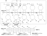
- FIG. 1 is a diagram showing an example of an outline of a rolling mill equipped with a plate wedge ratio acquisition device and a plate wedge ratio control device of the present invention.
- FIG. 4 is a diagram showing an example of a manner in which a metal strip meanders during rolling.
- FIG. 13 is a diagram showing an example of a calculation flow of a plate wedge ratio estimation formula in the plate wedge ratio acquisition method of the present invention.
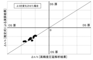
- FIG. 13 is a diagram showing an example of a verification result in which the coefficient A1 of the relational expression (1) is obtained based on the calculation result of the delivery plate wedge ratio ⁇ h/h when only the leveling amount ⁇ S is changed by high-precision rolling analysis.
- FIG. 13 is a diagram showing an example of a verification result in which the coefficient A2 of the relational expression (1) is obtained based on the calculation result of the delivery plate wedge ratio when only the meandering amount ⁇ Y is changed by a high-precision rolling analysis.
- FIG. 13 is a diagram showing an example of a verification result in which the coefficient A3 in the relational expression (1) is obtained based on the calculation result of the exit plate wedge ratio ⁇ h/h when only the entry plate wedge ratio ⁇ H/H is changed by a high-precision rolling analysis.
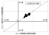
- FIG. 13 is a diagram showing an example of a verification result in which the coefficient A4 in the relational expression (1) is obtained based on the calculation result of the delivery plate wedge ratio ⁇ h/h when only the mill constant difference ⁇ K is changed by high-precision rolling analysis.
- FIG. 13 is a diagram showing an example of a result of comparing the calculation result of the delivery plate wedge ratio ⁇ h/h estimation formula and the high-precision rolling analysis result when only the leveling amount ⁇ S is changed.
- FIG. 13 is a diagram showing an example of a result of comparing a calculation result of an estimation formula for the delivery sheet wedge ratio ⁇ h/h and a high-precision rolling analysis result when only the meandering amount ⁇ Y is changed.
- FIG. 13 is a diagram showing an example of a result of comparing the calculation result of the exit plate wedge ratio ⁇ h/h estimation formula with the high-precision rolling analysis result when only the entry plate wedge ratio ⁇ H/H is changed.
- FIG. 13 is a diagram showing an example of a comparison result between the calculation result of the delivery plate wedge ratio ⁇ h/h estimation formula and the high-precision rolling analysis result when only the mill constant difference ⁇ K is changed.
- FIG. 13 is a diagram showing an example of a comparison result between the calculation result of the exit plate wedge ratio ⁇ h/h estimation formula and the high-precision rolling analysis result when values such as the leveling amount ⁇ S, the meandering amount ⁇ Y, the entry plate wedge ratio ⁇ H/H, and the mill constant difference ⁇ K are changed within a realistic range.
- 1 is a diagram showing an example of an outline of a tandem rolling mill equipped with a plate wedge ratio acquisition device and a plate wedge ratio control device of the present invention.
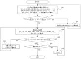
- FIG. 13 is a diagram showing an example of a plate wedge ratio control flow using the plate wedge ratio acquisition method of the present invention.
- FIG. 1 is a diagram showing an example of an outline of a rolling mill equipped with the plate wedge ratio acquisition device and plate wedge ratio control device of the present invention
- FIG. 2 is a diagram showing an example of the way in which a metal strip plate meanders during rolling
- FIG. 3 is a diagram showing an example of a calculation flow of the plate wedge ratio estimation formula in the plate wedge ratio acquisition method of the present invention
- FIGs. 4 to 7 are diagrams showing an example of a verification result for determining each of the coefficients described in relational formula (1) from the calculation result of the plate wedge ratio estimation formula by changing only one of the four variables in relational formula (1) described later, and FIGs.
- FIG. 8 to 11 are diagrams showing an example of a verification result for determining each of the coefficients described in relational formula (1) from the calculation result of the plate wedge ratio estimation formula by changing only one of the four variables in relational formula (1) described later.
- FIG. 12 shows an example of the results of comparing the calculation results of the plate wedge ratio estimation formula with the results of a separately performed high-precision rolling analysis by changing only one of the variables;
- FIG. 13 shows an example of the outline of a tandem rolling mill equipped with the plate wedge ratio acquisition device and plate wedge ratio control device of the present invention;
- FIG. 14 shows an example of a plate wedge ratio control flow using the plate wedge ratio acquisition method of the present invention.
- Figure 1 is a schematic diagram showing the configuration of the rolling mill including the plate wedge ratio acquisition device (plate wedge acquisition device) and plate wedge ratio control device of this embodiment.
- the rolling mill 100 shown in FIG. 1 is a finishing rolling mill for rolling a metal strip 1, and is equipped with an F1 stand 10, an F2 stand 20, an F3 stand 30, an F4 stand 40, an F5 stand 50, meandering amount detection cameras 81, 82, loopers 91, 92, 93, 94, a plate wedge ratio acquisition device 60, a plate wedge ratio control device 61, etc.
- the rolling mill 100 is not limited to having five rolling mill stands as shown in FIG. 1, but may have at least one stand. If the stand number is i, the entry thickness at the finishing mill Fi is Hi, the entry wedge is ⁇ Hi, the entry wedge ratio is ⁇ Hi/Hi, the exit thickness is hi, the exit wedge is ⁇ hi, and the exit wedge ratio is ⁇ hi/hi.
- each of the F1 stand 10, F2 stand 20, F3 stand 30, F4 stand 40, and F5 stand 50 will be explained using the F2 stand 20 as an example.
- the configuration of the other stands is approximately the same as that of the F2 stand 20, so details thereof will be omitted.
- the F2 stand 20 is a rolling mill equipped with an upper work roll 23 and a lower work roll 25 that are in direct contact with the metal strip 1, an upper backup roll 24 that supports the upper work roll 23 by contacting it, a lower backup roll 26 that supports the lower work roll 25 by contacting it, a reduction device 21 provided above the upper backup roll 24, and a load detector 22 provided below the lower backup roll 26.
- Information on the rolling load measured by the load detector 22, reduction information by the reduction device 21, and image information from the meandering amount detection cameras 81, 82 are transmitted to the plate wedge ratio acquisition device 60 and the plate wedge ratio control device 61 via communication lines 62, 63.
- the roll configuration of the rolling mill is not limited to the above-mentioned form, and it is sufficient to have a minimum of upper and lower work rolls.
- Loopers 91, 92, 93, and 94 are installed between F1 stand 10, F2 stand 20, F3 stand 30, F4 stand 40, and F5 stand 50, respectively, to control the tension in the rolling direction of the metal strip 1.
- the meandering amount detection camera 81 is provided at a position where it can capture an image including the metal strip 1 on the entry side of the F2 stand 20 and the exit side of the F1 stand 10.
- the meandering amount detection camera 82 is provided at a position where it can capture an image including the metal strip 1 on the exit side of the F2 stand 20 and the entry side of the F3 stand 30.
- the meandering amount detection cameras 81, 82 capture images including the metal strip 1 from directly above the metal strip 1 or diagonally above, for example, at intervals shorter than 0.1 seconds, preferably in video format, and the data of the captured image or data converted into the meandering amount is transmitted to the plate wedge ratio acquisition device 60 via the communication line 62, and the meandering amount ⁇ Y at the position of the F2 stand 20 is derived.
- an X-ray plate profile meter (plate profile meter 86 in FIG. 13) on the exit side of the final stand of the rolling mill 100 (F5 stand 50 in FIG. 1) to measure the final exit plate profile (plate thickness distribution in the plate width direction) and check whether the plate profile is as specified.
- the plate wedge ratio acquisition device 60 and the plate wedge ratio control device 61 are devices that are composed of a computer that controls the operation of each device in the rolling mill 100, and preferably include a CPU, a storage medium, a display device, etc.
- the plate wedge ratio acquisition device 60 can determine at least one of the following four measured values: leveling amount ⁇ S (measured value), which is the difference in the gap between the operation side and drive side of the upper work roll 23 and lower work roll 25 of the F2 stand 20; meandering amount ⁇ Y (measured value) of the metal strip 1 at the pressing position of the upper work roll 23 and lower work roll 25 of the F2 stand 20; rolling load difference ratio ⁇ P/P (measured value), which is the ratio of the rolling load difference ⁇ P, which is the difference between the respective rolling loads applied to the operation side and drive side of the upper work roll 23 and lower work roll 25 of the F2 stand 20, to the total rolling force P of the F2 stand 20; and mill constant difference ⁇ K (previously measured), which is the difference between the respective mill constants on the operation side and drive side of the F2 stand 20.
- the meandering amount ⁇ Y in the F2 stand 20 here is a value within the rolling mill work roll gap, so it is a value calculated using two values: the meandering amount on the entry side of the rolling mill detected by the meandering amount detection camera 81 and the meandering amount on the exit side of the rolling mill detected by the meandering amount detection camera 82.
- the case of calculating the plate wedge ratio is explained, but when calculating the plate wedge, the plate wedge can be calculated by multiplying the calculated plate wedge ratio by a known plate thickness, so details are omitted.
- the plate wedge ratio acquisition device 60 can further determine at least one of the entry plate wedge ⁇ H of the F2 stand 20 and the entry plate wedge ratio ⁇ H/H, which is the ratio between the entry plate wedge ⁇ H and the entry plate thickness H at the center of the width of the metal strip 1, based on the leveling amount ⁇ S (measured value), meandering amount ⁇ Y (measured value), rolling load difference ratio ⁇ P/P (measured value), and mill constant difference ⁇ K (previously measured) of the F2 stand 20.
- the entry plate wedge ⁇ H can be determined by multiplying the determined entry plate wedge ratio ⁇ H/H by the known entry plate thickness H, so details will be omitted.
- the following relational expression (1) expresses the exit plate wedge ratio ⁇ h/h by multiplying each of the four independent variables, the leveling amount ⁇ S, the meandering amount ⁇ Y, the entry plate wedge ratio ⁇ H/H, and the mill constant difference ⁇ K, by a specific coefficient and then linearly combining them.
- the following relational expression (2) expresses the rolling load difference ratio ⁇ P/P by multiplying each of the four independent variables, the leveling amount ⁇ S, the meandering amount ⁇ Y, the entry plate wedge ratio ⁇ H/H, and the mill constant difference ⁇ K, by a specific coefficient and then linearly combining them.
- the plate wedge ratio acquisition device 60 can preferably determine the exit plate wedge ratio ⁇ h/h using the known measured values of leveling amount ⁇ S, meandering amount ⁇ Y, rolling load difference ratio ⁇ P/P, and mill constant difference ⁇ K by eliminating the entry plate wedge ratio ⁇ H/H from the following relational expression (1) (exit plate wedge ratio estimation expression) for the exit plate wedge ratio ⁇ h/h and the following relational expression (2) (rolling load difference ratio estimation expression) for the rolling load difference ratio ⁇ P/P to determine the following relational expression (3).
- the plate wedge ratio acquisition device 60 can obtain the following relational expression (4) by shifting the term ⁇ H/H in relational expression (2) to the left side and shifting ⁇ P/P to the right side, thereby obtaining the inlet plate wedge ratio ⁇ H/H using the known measured values of the leveling amount ⁇ S, the meandering amount ⁇ Y, the rolling load difference ratio ⁇ P/P, and the mill constant difference ⁇ K.
- ⁇ H/H F1 ⁇ S+ F2 ⁇ Y+ F3 ⁇ ( ⁇ P/P)+ F4 ⁇ K (4)
- A1 , A2 , A3 , A4 , C1 , C2 , C3 , C4 , D1 , D2 , D3 , D4 , and F1 , F2 , F3 , F4 are coefficients specific to each rolling mill.
- the plate wedge ratio acquisition device 60 obtains the relational expressions (5) and ( 6) by regarding the coefficients A1 , A2 , A3 , A4 , C1 , C2 , C3 , and C4 as functions of the inlet plate thickness H, the plate width W of the metal strip 1, the rolling reduction Re, and the total rolling force P as independent variables.
- the coefficients D1 , D2 , D3 , D4 , F1 , F2 , F3 , and F4 can be derived from the relational expressions (1), (2), (3), and (4) and expressed by the coefficients A1 , A2 , A3 , A4 , C1 , C2 , C3 , and C4 .
- Aj B0j ⁇ (H/ H0 ) B1j ⁇ (W/ W0 ) B2j ⁇ (Re/ Re0 ) B3j ⁇ (P/ P0 ) B4j ... (5)
- Re (H - h) / H ...
- Re 0 (H 0 -h 0 ) / H 0 ...
- H 0 ", "W 0 ", “Re 0 ", and “P 0” are constant values that are the reference values of the entry thickness, width, reduction, and total rolling force used for normalization
- B kj " and "E kj " are constant values that, for example, the F2 stand 20 has as individual values, and are obtained in advance by high-precision rolling analysis to complete the relational expressions (5) and (6).
- k 0, 1, 2, 3, and 4.
- the high-precision rolling analysis used here is an analysis method that can accurately simulate the rolling state, such as the three-dimensional finite element method, and any analysis method may be used as long as it can accurately simulate the rolling state.
- the reduction rate Re is obtained by the relational expression (7).
- the reference value of the reduction rate "Re 0 " can be obtained by the relational expression (8), where h 0 is the reference value of the delivery thickness.
- the "reference value" used in these equations (5) to (8) is a standard value that is assumed when rolling with that rolling mill, and is a representative value such as the median value when the rolling mill in question is in operation.
- the rolling mill 100 by installing cameras for detecting the amount of meandering at the entry and exit of each stand, it is possible to determine the plate wedge or plate wedge ratio of the metal strip 1 at the entry and/or exit of each rolling mill stand other than the F2 stand 20. The details are the same, so a description is omitted.
- the plate wedge ratio control device 61 also outputs a signal of the leveling amount ⁇ S to be achieved to the reduction device 21 in the case of F2 stand 20 via communication line 64 so that the difference ( ⁇ h/h- ⁇ H/H) between the exit plate wedge ratio ⁇ h/h and the entry plate wedge ratio ⁇ H/H obtained by the plate wedge ratio acquisition device 60 satisfies the following relational expression (9), or if the difference ( ⁇ h/h- ⁇ H/H) does not satisfy the following relational expression (9), correct the leveling amount ⁇ S to satisfy the relational expression (9).
- Lmin ⁇ h/h ⁇ H/H ⁇ Lmax (9)
- Lmin is the minimum allowable value in the allowable range of the difference between the exit plate wedge ratio ⁇ h/h and the entry plate wedge ratio ⁇ H/H
- Lmax is the maximum allowable value
- the plate wedge ratio acquisition device 60 After the leveling amount ⁇ S by the reduction device 21 is corrected by the control of the plate wedge ratio control device 61, it is desirable for the plate wedge ratio acquisition device 60 to update the corrected leveling amount ⁇ S, the rolling load difference ratio ⁇ P/P that has changed as a result of the correction of the leveling amount ⁇ S, and the meandering amount ⁇ Y after the leveling amount ⁇ S has been corrected, and to re-determine the exit plate wedge ratio ⁇ h/h using the relational expression (3).
- the exit plate wedge ratio ⁇ h/h was considered to be a function including the entry plate wedge ratio ⁇ H/H, such as function f( ⁇ S, ⁇ Y, ⁇ H/H, ⁇ K, ). For this reason, it was thought that the existence of a shape measurement system such as a plate profile meter was essential.
- the inventors came up with the idea of finding the exit plate wedge ratio ⁇ h/h by coupling the exit plate wedge ratio estimation equation of relational expression (1) with the rolling load difference ratio estimation equation of relational expression (2).
- the exit plate wedge ratio ⁇ h/h and the rolling load difference ratio ⁇ P/P they created an exit plate wedge ratio estimation equation and a rolling load difference ratio estimation equation that are linear combination equations using four independent variables ⁇ S, ⁇ Y, ⁇ H/H, and ⁇ K.
- the entry plate wedge ratio ⁇ H/H is an unknown quantity, but ⁇ H/H can be estimated by transferring the measured value ⁇ P/P to the right side and the unknown term ⁇ H/H to the left side.
- the exit plate wedge ratio ⁇ h/h can be obtained using the known values ⁇ S, ⁇ Y, ⁇ P/P, and ⁇ K. With this method of obtaining the exit plate wedge ratio, it was conceived that it is possible to obtain the exit plate wedge or the exit plate wedge ratio while omitting the entry plate profiler.
- the inventors therefore conducted an intensive investigation into the rolling mill parameters for estimating the exit plate wedge ratio ⁇ h/h, and found that (1) the leveling amount ⁇ S, (2) the plate meandering amount ⁇ Y, (3) the entry plate wedge ratio ⁇ H/H, and (4) the mill constant difference ⁇ K have a large effect on the change in the exit plate wedge.
- the entry plate wedge ratio ⁇ H/H is an unknown quantity
- the inventors came up with the idea of creating relational equation (2), which is an estimation equation for the rolling load difference ratio ⁇ P/P as a relational equation having the same parameters, and eliminating the unknown entry plate wedge ratio ⁇ H/H.
- ⁇ S is the leveling amount
- ⁇ Y is the amount of meandering of the metal strip 1 at the rolling mill position
- ⁇ K is the mill constant difference, which are known values
- the exit center plate thickness h and entry center plate thickness H are also known values.
- ⁇ P/P g( ⁇ S, ⁇ Y, ⁇ H/H, ⁇ K) ... (11)
- this relational expression (11) can be written as the above-mentioned relational expression (2), but by moving the term ⁇ H/H to the left side of relational expression (2) and moving ⁇ P/P to the right side, the above-mentioned relational expression (4) can be obtained, and ⁇ H/H can be calculated.
- the entry plate wedge ratio ⁇ H/H can be calculated from relational expression (4).
- the rolling conditions (representative value calculation conditions) such as the inlet and outlet thickness, width, and deformation resistance of the metal strip 1, as well as the rolling mill equipment conditions such as roll size are selected (S11).
- a high-precision rolling analysis is performed (S13), and a coefficient Aj indicating the gradient of the relationship between the disturbance and ⁇ h/h is calculated for each calculation case, and a coefficient Cj indicating the gradient of the relationship between the disturbance and ⁇ P/P is calculated for each calculation case (S14).
- Fig. 4 shows the result when only the leveling amount ⁇ S is changed, and A1 is obtained from the gradient in the figure.
- Fig. 5 shows the result when only the meandering amount ⁇ Y is changed, and A2 is obtained from the gradient in the figure.
- Fig. 6 shows the result when only the entry plate wedge ratio ⁇ H/H is changed, and A3 is obtained from the gradient in the figure.
- Fig. 7 shows the result when only the mill constant difference ⁇ K is changed, and A4 is obtained from the gradient in the figure. It is desirable to change the disturbance by about ⁇ 20% from the representative value (reference value) and examine it.
- Figs. 8 to 12 An example of a comparison between the calculation result of the exit plate wedge ratio ⁇ h/h obtained from the exit plate wedge ratio estimation formula and the high-precision rolling analysis result is shown in Figs. 8 to 12.
- Fig. 8 shows the case where only the leveling amount ⁇ S is changed
- Fig. 9 shows the case where only the meandering amount ⁇ Y is changed
- Fig. 10 shows the case where only the entry plate wedge ratio ⁇ H/H is changed
- Fig. 11 shows the case where only the mill constant difference ⁇ K is changed
- Fig. 12 shows the case where the values of the leveling amount ⁇ S, meandering amount ⁇ Y, entry plate wedge ratio ⁇ H/H, mill constant difference ⁇ K, etc. are changed within a realistic range.
- the process in Figure 3 is a flow for constructing a model for estimating the entry or exit plate wedge ratio of the rolling mill, and must be executed in advance, prior to rolling.
- the created exit plate wedge ratio estimation equation (relationship (1)), rolling load difference ratio estimation equation (relationship (2)), and equations (3) and (4) derived from these estimation equations are incorporated into plate wedge ratio acquisition device 60, and ⁇ S, ⁇ Y, ⁇ P/P, and ⁇ K are taken in real time during rolling, and the entry plate wedge ratio ⁇ H/H and exit plate wedge ratio ⁇ h/h are calculated.
- the control of the operation of each device by the plate wedge ratio acquisition device 60 and the plate wedge ratio control device 61 as described above is executed based on various programs recorded in the memory unit.
- the control processing of the operation executed by the plate wedge ratio acquisition device 60 and the plate wedge ratio control device 61 may be integrated into one program, or each may be separated into multiple programs, or a combination of these.
- some or all of the programs may be realized by dedicated hardware, or may be modularized.
- the tandem rolling mill 100A shown in FIG. 13 is equipped with meander amount detection cameras 80, 81, 82, 83, 84, and 85, and a plate profile meter 86 for each of the configurations of the rolling mill 100 shown in FIG. 1.
- the plate wedge ratio acquisition device 60A in this tandem rolling mill 100A not only calculates the entry and exit plate wedge ratios at the F2 stand 20, but also calculates the entry and exit plate wedge ratios at the F1 stand 10, F3 stand 30, F4 stand 40, and F5 stand 50.
- the plate wedge ratio control device 61A also performs leveling control at the F1 stand 10, F3 stand 30, F4 stand 40, and F5 stand 50 in addition to leveling control at the F2 stand 20.
- information on the meander amount ⁇ Y at the entry and exit of each stand acquired by the meander amount detection cameras 80, 81, 82, 83, 84, 85, and information on the reduction by the reduction devices 11, 21, 31, 41, 51 (leveling amount ⁇ S, entry side plate thickness H and exit side plate thickness h at the center of the width of the metal strip 1) are transmitted via communication line 62A, and information on the rolling load at each stand measured by the load detectors 12, 22, 32, 42, 52 (rolling load difference ⁇ P, total rolling force P of the rolling mill) is transmitted via communication line 63A to the plate wedge ratio acquisition device 60A.
- the plate profiler 86 is a measuring device that measures the thickness distribution in the width direction of the metal strip 1, and is provided on the exit side of F5 stand 50, which is the final stand. Information on the thickness distribution in the width direction of the metal strip 1 at the exit side of F5 stand 50 measured by the plate profiler 86 is transmitted to the plate wedge ratio acquisition device 60A and plate wedge ratio control device 61A via communication line 62A, and the calculation accuracy of the exit plate wedge ratio ⁇ h/h of F5 stand 50 obtained by the exit plate wedge ratio estimation formula can be verified.
- the rolling load difference ratio ⁇ P/P, leveling amount ⁇ S, meandering amount ⁇ Y, and mill constant difference ⁇ K at F4 stand 40, and the calculation result of the exit plate wedge ratio ⁇ h i+1 /h i+1 at F3 stand 30 obtained by plate wedge ratio acquisition device 60A are used as the entry plate wedge ratio ⁇ H i+2 /H i+2 at the corresponding F4 stand 40, and the exit plate wedge ratio ⁇ h i+2 /h i+2 of F4 stand 40 is obtained from the above-mentioned relational equation (1).
- the rolling load difference ratio ⁇ P/P, leveling amount ⁇ S, meandering amount ⁇ Y, and mill constant difference ⁇ K at F5 stand 50, and the calculation result of the exit plate wedge ratio ⁇ h i+2 /h i+2 at F4 stand 40 obtained by plate wedge ratio acquisition device 60A are used as the entry plate wedge ratio ⁇ H i+3 /H i+3 at the corresponding F5 stand 50, and the exit plate wedge ratio ⁇ h i+3 /h i+3 of F5 stand 50 is obtained from the above-mentioned relational equation (1).
- the plate wedge ratio control device 61A corrects the leveling amount ⁇ S at the F3 stand 30 so that the difference ( ⁇ h i+1 /h i+1 - ⁇ H i+1 /H i+ 1 ) between the entry plate wedge ratio ⁇ H i+1 /H i +1 and the exit plate wedge ratio ⁇ h i + 1 /h i+1 determined by the plate wedge ratio acquisition device 60A for the F3 stand 30 satisfies relational equation (9), or if the difference ( ⁇ h i+1 /h i+1 - ⁇ H i+1 /H i+1 ) does not satisfy relational equation (9), it corrects the leveling amount ⁇ S at the F3 stand 30 so that it satisfies relational equation (9).
- the plate wedge ratio control device 61A corrects the leveling amount ⁇ S at F4 stand 40 so that the difference ( ⁇ h i+2 /h i+2 - ⁇ H i+2 /H i+2 ) between the entry plate wedge ratio ⁇ H i+2 /H i + 2 and the exit plate wedge ratio ⁇ h i + 2 /h i+2 determined by the plate wedge ratio acquisition device 60A for F4 stand 40 satisfies relationship (9), or if the difference ( ⁇ h i+2 /h i+2 - ⁇ H i+2 /H i+2 ) does not satisfy relationship (9), it corrects the leveling amount ⁇ S at F4 stand 40 so that it satisfies relationship (9).
- the plate wedge ratio control device 61 corrects the leveling amount ⁇ S at F5 stand 50 so that the difference ( ⁇ h i+3 /h i+3 - ⁇ H i +3 /H i+3) between the entry plate wedge ratio ⁇ H i+3 /H i+ 3 and the exit plate wedge ratio ⁇ h i +3 /h i+3 determined by the plate wedge ratio acquisition device 60A for F5 stand 50 satisfies relational equation (9), or if the difference ( ⁇ h i+3 /h i+3 - ⁇ H i+3 /H i+3 ) does not satisfy relational equation (9), it corrects the leveling amount ⁇ S at F5 stand 50 so that it satisfies relational equation (9).
- the plate wedge ratio control device 61A can correct the leveling amount ⁇ S for the F2 stand 20, except for the most upstream F1 stand 10, in a manner similar to that described above.
- the exit plate wedge ratio ⁇ h/h and the entry plate wedge ratio ⁇ H/H are found using the relational expressions (3) and (4), and if ( ⁇ h/h - ⁇ H/H) does not satisfy the relational expression (9), the leveling amount ⁇ S is corrected so that it satisfies the relational expression (9).
- the plate wedge ratio control device 61A judges whether the difference ( ⁇ hi/hi- ⁇ Hi/Hi) between the exit plate wedge ratio ⁇ hi/hi and the entry plate wedge ratio ⁇ Hi/Hi calculated by the plate wedge ratio acquisition device 60A is within the allowable range (Lmin or more and Lmax or less) (S22). If it is judged to be within the allowable range, the process proceeds to S24, and if it is judged to be outside the allowable range, the process proceeds to S23.
- the plate wedge ratio control device 61A corrects the leveling amount ⁇ S, updates the meandering amount ⁇ Y and the rolling load difference ratio ⁇ P/P that have changed as a result of this correction (S21), and repeats the correction of the leveling amount ⁇ S by making another judgment (S22) and proceeding to S24.
- plate wedge ratio control device 61A judges whether or not the difference ( ⁇ h i+1 /h i+ 1 - ⁇ H i+1 /H i+1 ) between the exit plate wedge ratio ⁇ h i+1 /h i+1 and the entry plate wedge ratio ⁇ H i +1 /h i+1 calculated by plate wedge ratio acquisition device 60A is within the allowable range (Lmin or more and Lmax or less) (S25). If it is judged to be within the allowable range, processing proceeds to S27, and if it is judged to be outside the allowable range, processing proceeds to S26.
- the plate wedge ratio control device 61A corrects the leveling amount ⁇ S for the relevant stand, updates the meandering amount ⁇ Y and rolling load difference ratio ⁇ P/P that have changed in association with this correction (S24), and repeats the correction of the leveling amount ⁇ S by making a judgment again (S25) and proceeding to S27.
- the plate wedge ratio acquisition method for determining the plate wedge of the metal strip 1 at the F1 stand 10, F2 stand 20, F3 stand 30, F4 stand 40, and F5 stand 50 in the present embodiment described above is to determine the exit plate wedge ⁇ h of the F2 stand 20 and the exit plate wedge ratio ⁇ h/h, which is the ratio of the exit plate wedge ⁇ h to the exit plate thickness h at the center of the width of the metal strip 1, based on the rolling load difference ratio ⁇ P/P, which is the ratio of the rolling load difference ⁇ P, which is the difference between the rolling loads applied to the operating side and driving side of the upper work roll 23 and the lower work roll 25, and the total rolling force P of the F2 stand 20, the leveling amount ⁇ S, which is the difference in the gap between the operating side and driving side of the upper work roll 23 and the lower work roll 25, the meandering amount ⁇ Y of the metal strip 1 at the position of the F2 stand 20, and the mill constant difference ⁇ K, which is the difference between the mill constants of the operating side and driving side of
- the exit plate wedge can be estimated from measurements around the rolling mill in this way, it becomes possible to grasp the state of the exit plate wedge of the rolling mill, which affects the amount of meandering of the metal strip 1 during rolling, without the need for a plate profile meter.
- This makes it possible to realize operator intervention or automatic intervention at the rolling mill in order to reduce the difference in plate wedge ratio at each stand, without relying solely on the operator as in the past, thereby improving the performance of the rolling state and the quality of the rolled material product (final coil) compared to the past.
- the entry plate wedge ⁇ H of F2 stand 20 and the entry plate wedge ratio ⁇ H/H which is the ratio of the entry plate wedge ⁇ H to the entry plate thickness H at the center of the width of the metal strip 1, can be calculated based on the rolling load difference ratio ⁇ P/P, the leveling amount ⁇ S, the meandering amount ⁇ Y, and the mill constant difference ⁇ K. This makes it possible to estimate the entry plate wedge as well, and to estimate the state of the exit plate wedge with higher accuracy, thereby achieving further quality improvements in the rolled material product (final coil).
- the exit plate wedge ratio ⁇ h/h can be obtained using the known values of the rolling load difference ratio ⁇ P/P, the leveling amount ⁇ S, the meandering amount ⁇ Y, and the mill constant difference ⁇ K to obtain the relational expression (3).
- the term ⁇ H/H in the relational expression (2) is moved to the left side and ⁇ P/P is moved to the right side to obtain the following relational expression (4).
- the entry plate wedge ratio ⁇ H/H can be obtained using the known values of the rolling load difference ratio ⁇ P/P, the leveling amount ⁇ S, the meandering amount ⁇ Y, and the mill constant difference ⁇ K.
- the entry plate wedge ratio ⁇ H/H and the exit plate wedge ratio ⁇ h/h can be estimated without using complicated relational expressions, and estimation processing with a small computational load can be realized.
- A1 , A2 , A3 , A4 , C1 , C2 , C3 , and C4 are functions obtained from relational equations (5) and (6) with the entry plate thickness H, the plate width W of the metal strip 1, the rolling reduction Re, and the total rolling force P as variables, and the coefficients D1, D2, D3, D4, F1, F2, F3, and F4 of relational equations (3) and (4) are expressed as A1 , A2 , A3 , A4 , C1 , C2 , C3 , and C4 , making it possible to more easily estimate the exit plate wedge ⁇ h and the exit plate wedge ratio ⁇ h /h.
- the rolling conditions are changed so that the difference between the exit plate wedge ratio and the entry plate wedge ratio can be made smaller, and rolling that can obtain higher quality plates can be realized.
- the leveling amount ⁇ S can be corrected so as to satisfy the relational expression (9), thereby suppressing the occurrence of meandering of the metal strip 1 during rolling, and a plate of a high level of quality can be obtained more efficiently.
- the exit plate wedge ratio ⁇ h/h is calculated again using the relational expression (3) based on the corrected leveling amount ⁇ S, the rolling load difference ratio ⁇ P/P that has changed as a result of the correction of the leveling amount ⁇ S, and the meandering amount ⁇ Y after the leveling amount ⁇ S is corrected, making it possible to follow changes in the exit plate wedge ⁇ h and the exit plate wedge ratio ⁇ h/h due to changes in rolling conditions.
Landscapes
- Engineering & Computer Science (AREA)
- Mechanical Engineering (AREA)
- Control Of Metal Rolling (AREA)
Priority Applications (2)
| Application Number | Priority Date | Filing Date | Title |
|---|---|---|---|
| JP2024561088A JPWO2024116359A1 (https=) | 2022-11-30 | 2022-11-30 | |
| PCT/JP2022/044293 WO2024116359A1 (ja) | 2022-11-30 | 2022-11-30 | 板ウェッジ取得方法及び板ウェッジ比率制御方法、並びに板ウェッジ取得装置及び板ウェッジ比率制御装置 |
Applications Claiming Priority (1)
| Application Number | Priority Date | Filing Date | Title |
|---|---|---|---|
| PCT/JP2022/044293 WO2024116359A1 (ja) | 2022-11-30 | 2022-11-30 | 板ウェッジ取得方法及び板ウェッジ比率制御方法、並びに板ウェッジ取得装置及び板ウェッジ比率制御装置 |
Publications (1)
| Publication Number | Publication Date |
|---|---|
| WO2024116359A1 true WO2024116359A1 (ja) | 2024-06-06 |
Family
ID=91323139
Family Applications (1)
| Application Number | Title | Priority Date | Filing Date |
|---|---|---|---|
| PCT/JP2022/044293 Ceased WO2024116359A1 (ja) | 2022-11-30 | 2022-11-30 | 板ウェッジ取得方法及び板ウェッジ比率制御方法、並びに板ウェッジ取得装置及び板ウェッジ比率制御装置 |
Country Status (2)
| Country | Link |
|---|---|
| JP (1) | JPWO2024116359A1 (https=) |
| WO (1) | WO2024116359A1 (https=) |
Citations (3)
| Publication number | Priority date | Publication date | Assignee | Title |
|---|---|---|---|---|
| JPS6329606B2 (https=) * | 1980-12-26 | 1988-06-14 | Nippon Steel Corp | |
| JP2000254720A (ja) * | 1999-01-06 | 2000-09-19 | Kobe Steel Ltd | 圧延機における板厚制御方法 |
| JP2013006195A (ja) * | 2011-06-24 | 2013-01-10 | Kobe Steel Ltd | 圧延機での板厚制御方法 |
-
2022
- 2022-11-30 JP JP2024561088A patent/JPWO2024116359A1/ja active Pending
- 2022-11-30 WO PCT/JP2022/044293 patent/WO2024116359A1/ja not_active Ceased
Patent Citations (3)
| Publication number | Priority date | Publication date | Assignee | Title |
|---|---|---|---|---|
| JPS6329606B2 (https=) * | 1980-12-26 | 1988-06-14 | Nippon Steel Corp | |
| JP2000254720A (ja) * | 1999-01-06 | 2000-09-19 | Kobe Steel Ltd | 圧延機における板厚制御方法 |
| JP2013006195A (ja) * | 2011-06-24 | 2013-01-10 | Kobe Steel Ltd | 圧延機での板厚制御方法 |
Non-Patent Citations (1)
| Title |
|---|
| KAZUO OHMORI, MASATOSHI INOUE, TAKANORI MIYAKE, YUJI TANAKA, KATSUMI NISHIZAKI: "Development of Camber Control Technique in Plate Rolling", TETSU TOHAGANE - JOURNAL OF THE IRON AND STEEL INSTITUTE OF JAPAN, vol. 72, no. 16, 1 January 1986 (1986-01-01), pages 2248 - 2255, XP009557174, ISSN: 1883-2954, DOI: 10.2355/tetsutohagane1955.72.16_2248 * |
Also Published As
| Publication number | Publication date |
|---|---|
| JPWO2024116359A1 (https=) | 2024-06-06 |
Similar Documents
| Publication | Publication Date | Title |
|---|---|---|
| JP2013006195A (ja) | 圧延機での板厚制御方法 | |
| WO2024116359A1 (ja) | 板ウェッジ取得方法及び板ウェッジ比率制御方法、並びに板ウェッジ取得装置及び板ウェッジ比率制御装置 | |
| CN108971237B (zh) | 用于金属轧制应用的轴承浮动补偿 | |
| JP2005118840A (ja) | 冷間圧延における板形状制御方法 | |
| JP3067879B2 (ja) | ストリップ圧延における形状制御方法 | |
| CN114054514A (zh) | 轧机的蛇行控制装置 | |
| CN113056337B (zh) | 轧制设备及轧制方法 | |
| JP4306273B2 (ja) | タンデム圧延機におけるストリップの蛇行制御装置及び蛇行制御方法 | |
| JP7314921B2 (ja) | 熱間圧延鋼帯の蛇行制御方法、蛇行制御装置及び熱間圧延設備 | |
| KR100929015B1 (ko) | 압연재 소성계수 보정에 의한 예측압연하중 보정방법 | |
| WO2023037409A1 (ja) | レベリング制御装置、およびそれを備えた圧延設備、並びにレベリング制御方法 | |
| CN113710386B (zh) | 被轧制材料的蛇行控制方法 | |
| KR20060104429A (ko) | 사상압연 폭 마진 제어장치 및 그 방법 | |
| JP7736017B2 (ja) | 被圧延材の蛇行量予測装置、蛇行量制御装置、蛇行量予測方法、蛇行量制御方法、及び金属帯の製造方法 | |
| JP4223344B2 (ja) | 連続圧延機の板厚推定方法及びその推定方法を用いた板厚制御方法 | |
| JPS6149722A (ja) | 鋼ストリツプの板厚制御方法 | |
| JP7736177B2 (ja) | 板クラウン制御装置 | |
| JP2957402B2 (ja) | 熱間圧延における蛇行制御方法 | |
| JP7298019B2 (ja) | 圧延機および圧延方法 | |
| JPH10166019A (ja) | 圧延ラインにおける圧延材の形状制御方法 | |
| JPS62137114A (ja) | 厚板の板幅制御方法 | |
| JP4676661B2 (ja) | 板圧延機の圧延荷重測定装置の調整方法および圧延方法 | |
| KR100523218B1 (ko) | 사상압연 입측 엣저 갭 설정 장치 및 그 방법 | |
| JPH0839123A (ja) | 熱間圧延における絞り込み防止方法 | |
| JP2661497B2 (ja) | 板クラウン制御装置及び熱間圧延時の板クラウン制御方法 |
Legal Events
| Date | Code | Title | Description |
|---|---|---|---|
| 121 | Ep: the epo has been informed by wipo that ep was designated in this application |
Ref document number: 22967192 Country of ref document: EP Kind code of ref document: A1 |
|
| WWE | Wipo information: entry into national phase |
Ref document number: 2024561088 Country of ref document: JP |
|
| NENP | Non-entry into the national phase |
Ref country code: DE |
|
| 122 | Ep: pct application non-entry in european phase |
Ref document number: 22967192 Country of ref document: EP Kind code of ref document: A1 |