WO2024116296A1 - 冷却装置を制御する制御装置 - Google Patents
冷却装置を制御する制御装置 Download PDFInfo
- Publication number
- WO2024116296A1 WO2024116296A1 PCT/JP2022/044044 JP2022044044W WO2024116296A1 WO 2024116296 A1 WO2024116296 A1 WO 2024116296A1 JP 2022044044 W JP2022044044 W JP 2022044044W WO 2024116296 A1 WO2024116296 A1 WO 2024116296A1
- Authority
- WO
- WIPO (PCT)
- Prior art keywords
- cooling
- motor
- time
- temperature
- calculation unit
- Prior art date
- Legal status (The legal status is an assumption and is not a legal conclusion. Google has not performed a legal analysis and makes no representation as to the accuracy of the status listed.)
- Ceased
Links
Images





Classifications
-
- H—ELECTRICITY
- H02—GENERATION; CONVERSION OR DISTRIBUTION OF ELECTRIC POWER
- H02P—CONTROL OR REGULATION OF ELECTRIC MOTORS, ELECTRIC GENERATORS OR DYNAMO-ELECTRIC CONVERTERS; CONTROLLING TRANSFORMERS, REACTORS OR CHOKE COILS
- H02P29/00—Arrangements for regulating or controlling electric motors, appropriate for both AC and DC motors
- H02P29/60—Controlling or determining the temperature of the motor or of the drive
- H02P29/62—Controlling or determining the temperature of the motor or of the drive for raising the temperature of the motor
Definitions
- This disclosure relates to a control device that controls a cooling device.
- the motors are cooled using a cooling device while they are running.
- a cooling device that rotates a cooling fan at a constant speed to send air to the motor to cool it.
- a cooling device that cools the motor by controlling the rotation speed of the cooling fan according to the motor temperature measured in real time (for example, Patent Document 1).
- the cooling capacity may not be able to keep up with fluctuations in the motor temperature. In this case, there is a risk that the motor will overheat. Therefore, there is a need for a control device for a cooling device that can prevent the cooling device from consuming more energy than necessary and prevent the motor from overheating.
- the control device disclosed herein includes a remaining time calculation unit that analyzes the operating program to calculate the remaining time until a reference time, a temperature information receiving unit that receives temperature information related to the temperature of the motor detected by a sensor, an operating time calculation unit that calculates the operable time of the motor based on at least the temperature information, the operating program, and a thermal model of the motor, and a cooling control unit that controls a cooling device that cools the motor based on the remaining time calculated by the remaining time calculation unit and the operable time calculated by the operating time calculation unit.
- FIG. 2 is a block diagram showing an example of a hardware configuration of an industrial machine in which the control device is implemented.
- FIG. FIG. 2 is a block diagram showing an example of functions of a control device according to the first embodiment
- 4 is an example of a graph showing a transition of the temperature of a motor.
- 4 is a flowchart showing an example of a flow of a process executed by a control device.
- FIG. 11 is a block diagram showing an example of functions of a control device according to a second embodiment.
- 4 is an example of a graph showing a transition of the temperature of a motor.
- 4 is a flowchart showing an example of a flow of a process executed by a control device.
- FIG. 13 is a block diagram showing an example of functions of a control device according to a third embodiment.
- 4 is a flowchart showing an example of a flow of a process executed by a control device.
- 4 is an example of a graph showing a transition of the temperature of a
- based on XX means “based on at least XX,” and includes cases where it is based on other elements in addition to XX. Furthermore, “based on XX” is not limited to cases where XX is used directly, but also includes cases where it is based on XX that has been calculated or processed. "XX” is any element (for example, any information).
- the control device is a device that controls the cooling device.
- the control device may further control an industrial machine. That is, the control device may be a device that controls the industrial machine. Furthermore, the control device may be a device separate from the device that controls the industrial machine. Below, an example in which the control device is a device that controls the industrial machine will be described.
- Industrial machinery is machinery that operates in industrial sites. Examples of industrial machinery include machine tools, injection molding machines, laser processing machines, 3D printers, and robots.
- FIG. 1 is a block diagram showing an example of the hardware configuration of an industrial machine in which a control device is implemented.
- the industrial machine 1 includes a control device 2, an input/output device 3, a servo amplifier 4, a servo motor 5, a spindle amplifier 6, a spindle motor 7, an auxiliary device 8, a sensor 9, and a cooling device 10.
- the control device 2 is, for example, a numerical control device that controls the industrial machine 1.
- the control device 2 includes, for example, a hardware processor 201, a bus 202, a ROM (Read Only Memory) 203, a RAM (Random Access Memory) 204, and a non-volatile memory 205.
- the hardware processor 201 is a processor that controls the entire control device 2 in accordance with a system program.
- the hardware processor 201 reads out the system program stored in the ROM 203 via the bus 202.
- the hardware processor 201 is, for example, a CPU (Central Processing Unit) or an electronic circuit.
- the bus 202 is a communication path that connects each piece of hardware in the control device 2 to each other. Each piece of hardware in the control device 2 exchanges data via the bus 202.
- ROM 203 is a storage device that stores system programs and the like. ROM 203 is a computer-readable storage medium.
- RAM 204 is a storage device that temporarily stores various data. RAM 204 functions as a working area for the hardware processor 201 to process various data.
- the non-volatile memory 205 is a storage device that retains data even when the control device 2 is powered off.
- the non-volatile memory 205 stores, for example, the operating program of the industrial machine 1.
- the non-volatile memory 205 is a computer-readable storage medium.
- the non-volatile memory 205 is, for example, a battery-backed memory or an SSD (Solid State Drive).
- the control device 2 further includes a first interface 206, an axis control circuit 207, a spindle control circuit 208, a PLC (Programmable Logic Controller) 209, an I/O unit 210, a second interface 211, and a third interface 212.
- a PLC Programmable Logic Controller
- the first interface 206 connects the bus 202 and the input/output device 3.
- the first interface 206 sends, for example, various data processed by the hardware processor 201 to the input/output device 3.
- the input/output device 3 receives various data via the first interface 206 and displays the various data.
- the input/output device 3 also accepts input of various data and sends the various data via the first interface 206 to, for example, the hardware processor 201.
- the input/output device 3 is, for example, a touch panel.
- the input/output device 3 is, for example, a capacitive touch panel.
- the touch panel is not limited to a capacitive touch panel, and may be a touch panel of another type.
- the input/output device 3 is installed in an operation panel (not shown) in which the control device 2 is stored.
- the axis control circuit 207 is a circuit for controlling the servo motor 5.
- the axis control circuit 207 receives control commands from the hardware processor 201 and sends various commands to the servo amplifier 4 for driving the servo motor 5.
- the axis control circuit 207 sends, for example, a torque command for controlling the torque of the servo motor 5 to the servo amplifier 4.
- the servo amplifier 4 receives commands from the axis control circuit 207 and supplies current to the servo motor 5.
- the servo motors 5 are driven by receiving a current supply from the servo amplifier 4.
- the servo motors 5 are provided for each control axis of the industrial machine 1. If the industrial machine 1 is a machine tool having five axes, the servo motors 5 include, for example, an X-axis servo motor, a Y-axis servo motor, a Z-axis servo motor, an A-axis servo motor, and a C-axis servo motor.
- the axis control circuit 207 and the servo amplifier 4 are provided for each servo motor 5.
- the servo motor 5 is connected to, for example, a ball screw that drives a tool post.
- a structure of the industrial machine 1, such as the tool post moves along a specified control axis.
- the servo motor 5 has a built-in encoder (not shown) that detects the position and feed speed of the control axis. Position feedback information and speed feedback information indicating the position and feed speed of the control axis detected by the encoder, respectively, are fed back to the axis control circuit 207. In this way, the axis control circuit 207 performs feedback control of each control axis.
- the spindle control circuit 208 is a circuit for controlling the spindle motor 7.
- the spindle control circuit 208 receives a control command from the hardware processor 201 and sends a command to the spindle amplifier 6 to drive the spindle motor 7.
- the spindle control circuit 208 sends, for example, a spindle speed command to the spindle amplifier 6 to control the rotation speed of the spindle motor 7.
- the spindle amplifier 6 receives commands from the spindle control circuit 208 and supplies current to the spindle motor 7.
- the spindle motor 7 is driven by a current supplied from the spindle amplifier 6.
- the spindle motor 7 is connected to the main shaft and rotates the main shaft.
- the PLC 209 is a device that executes a ladder program to control the auxiliary device 8.
- the PLC 209 sends commands to the auxiliary device 8 via the I/O unit 210.
- the I/O unit 210 is an interface that connects the PLC 209 and the auxiliary device 8.
- the I/O unit 210 sends commands received from the PLC 209 to the auxiliary device 8.
- the auxiliary device 8 is installed in the industrial machine 1 and performs auxiliary operations in the industrial machine 1.
- the auxiliary device 8 operates based on commands received from the I/O unit 210.
- the auxiliary device 8 may be a device installed in the periphery of the industrial machine 1.
- the auxiliary device 8 is, for example, a tool changer, a cutting fluid injection device, or an opening/closing door drive device.
- the second interface 211 connects the bus 202 and the sensor 9.
- the second interface 211 sends, for example, information acquired by the sensor 9 to the hardware processor 201 via the bus 202.
- the sensor 9 is a temperature sensor that detects the temperature of at least one of the servo motor 5 and the spindle motor 7.
- the sensor 9 sends temperature information regarding the detected temperatures of the servo motor 5 and the spindle motor 7 to, for example, the hardware processor 201 via the second interface 211.
- the sensor 9 is attached to, for example, the windings of the servo motor 5 and the spindle motor 7.
- the third interface 212 connects the cooling device 10 to the bus 202.
- the third interface 212 for example, sends commands from the hardware processor 201 to the cooling device 10.
- the cooling device 10 is a device that cools the motor.
- the cooling device 10 has a pump that sends fluid to the motor.
- the cooling device 10 includes a cooling fan that sends air to the motor.
- the cooling device 10 includes a gear pump that sends coolant to the motor.
- FIG. 2 is a block diagram showing an example of the functions of the control device 2 of the first embodiment.
- the control device 2 includes a storage unit 221, a remaining time calculation unit 222, a temperature information reception unit 223, an operation time calculation unit 224, and a cooling control unit 225.
- the storage unit 221 is realized, for example, by storing various information in the RAM 204 or the non-volatile memory 205.
- the remaining time calculation unit 222, the temperature information receiving unit 223, the operation time calculation unit 224, and the cooling control unit 225 are realized, for example, by the hardware processor 201 performing calculations using the system program stored in the ROM 203 and the various data stored in the non-volatile memory 205.
- the memory unit 221 stores, for example, an operation program, motor information, machine information, a thermal model, and an operable time calculation formula.
- the operation program is a program for operating the industrial machine 1.
- the operation program is, for example, a machining program for a machine tool.
- the machining program includes, for example, a command to specify the rotation speed of the spindle, a command to specify the feed rate of each axis, and a movement command for each axis using coordinate values.
- Motor information is information about the motor.
- the motor information includes the motor's resistance value, the motor's heat capacity, the motor's iron loss heat coefficient, and information about the motor's specifications.
- the information about the motor's specifications may include information indicating the motor's rated current, starting torque, starting current, etc.
- the iron loss heat coefficient will be described later.
- Machine information is information related to the industrial machine 1.
- the machine information may include information related to the specifications of the industrial machine 1.
- the machine information includes information indicating the weight of structures of the industrial machine 1 that move along each axis, such as the table of a machine tool.
- the machine information may also include information related to frictional forces that occur when each structure of the industrial machine 1 moves along each axis.
- the machine information may include, for example, information indicating the weight of a structure of the industrial machine 1 that rotates around each axis, such as the arm of a robot.
- the machine information may include information regarding the frictional force that occurs when each structure of the industrial machine 1 rotates around each axis.
- the thermal model is a mathematical formula that shows the relationship between the motor's operation and heat generation capacity when the operating program is executed.
- the thermal model is expressed, for example, by the following mathematical formula 1.
- Hm is the heat generation capacity of the motor
- I is the root mean square current value of the motor
- R is the resistance value of the motor
- N is the root mean square rotation speed of the motor
- H is the iron loss heat generation coefficient
- the heat generation capacity of the motor is an estimate of the amount of heat generated by the motor from the time the heat generation capacity is calculated until a reference time.
- the reference time is, for example, the time when the operating program being executed ends.
- the reference time may also be, for example, the time when an optional stop of the operating program is executed.
- the motor's root mean square current value is a value that indicates the average of the squares of the motor's current values at each time from the time the root mean square current value is calculated to a reference time.
- the root mean square current value is calculated based on the operating program, motor information, and machine information.
- Information about the machine specifications is used to calculate the motor's root mean square current value.
- Information about the frictional forces that occur when a structure, such as a table, moves along each axis may also be used to calculate the motor's root mean square current value.
- the motor resistance value is a value that indicates the resistance of the motor windings.
- the motor resistance value is a value that is measured in advance, or a value that is indicated by the motor's design information.
- the iron loss heat coefficient is a value that indicates the ratio of the amount of heat generated by a motor to the root mean square rotation speed of the motor when the motor performs a specified rotation operation.
- the iron loss heat coefficient may be determined in advance by experiment. Alternatively, the iron loss heat coefficient may be a value indicated by the design information.
- the operable time is calculated as the time until the motor reaches an overheated state, assuming that the cooling capacity of the cooling device 10 is maintained at the time of calculating the operable time.
- the formula for calculating the operable time is expressed, for example, by the following formula 2.
- Tt is the target temperature
- Tc is the current temperature
- Hm is the heat generation capacity of the motor
- Hr is the cooling capacity of the motor
- Cm is the heat capacity of the motor.
- the target temperature Tt is a temperature that the motor is to reach when the operation program is executed.
- the target temperature Tt is, for example, a temperature at which the motor reaches an overheated state. In other words, the target temperature Tt is the upper allowable temperature limit of the motor.
- the target temperature Tt of the motor is, for example, 100° C.
- the target temperature Tt of the motor may be stored in advance in the storage unit 221.
- the current temperature Tc is the temperature of the motor at the time when the operable time is calculated. That is, the current temperature Tc is temperature information related to the temperature of the motor.
- the current temperature Tc is acquired by the sensor 9.
- the motor cooling capacity Hr is a value indicating the capacity to cool the motor.
- the motor cooling capacity Hr differs depending on whether the motor is naturally cooled, air cooled, or water cooled.
- the motor cooling capacity Hr is expressed by Equation 3, Equation 4, or Equation 5 depending on whether the motor is naturally cooled, air cooled, or water cooled, respectively.
- the motor cooling capacity Hr is stored in advance in the storage unit 221.
- J1 is the heat removal coefficient of the motor when it is naturally cooled
- T E is the temperature of the environment in which the motor is installed.
- J3 is the heat removal coefficient when cooling with water
- Q is the flow rate of the cooling liquid
- the heat capacity Cm of the motor is the amount of heat required to increase the temperature of the motor by 1° C.
- the heat capacity Cm of the motor is measured in advance and stored in the storage unit 221.
- the remaining time calculation unit 222 analyzes the operation program and calculates the remaining time until the reference time. In other words, the remaining time is the time between the calculation point of the remaining time and the reference time. The remaining time calculation unit 222 calculates the remaining time based on the movement commands for each axis in the operation program, commands specifying the feed rate, and the like.
- the remaining time calculation unit 222 calculates the time until a reference time when the operation program starts to be executed and while the operation program is being executed. For example, the remaining time calculation unit 222 calculates the remaining time every 10 seconds while the operation program is being executed.
- the temperature information receiving unit 223 receives temperature information from the sensor 9 regarding the temperature of the motor detected by the sensor 9.
- the motor is, for example, a spindle motor 7 or a servo motor 5.
- the motor may be a linear motor provided in the industrial machine 1.
- the temperature information receiving unit 223 receives temperature information from the sensor 9 for each control cycle of the control device 2, for example.
- the operation time calculation unit 224 calculates the operation time of the motor based on at least the temperature information related to the temperature detected by the sensor 9, the operation program, and the thermal model of the motor.
- the operation time calculation unit 224 calculates the operation time of the motor using, for example, the operation time calculation formula described above. In this case, the operation time calculation unit 224 substitutes the information stored in the memory unit 221, etc., into the operation time calculation formula to calculate the operation time.
- the operation time calculation unit 224 calculates the operation time using, for example, the motor's resistance value, iron loss heat coefficient, target temperature, and heat capacity of the motor.
- the operation time calculation unit 224 also calculates the operation time using the calculated heat generation capacity of the motor and temperature information related to the motor's temperature.
- the operation time calculation unit 224 may use other formulas, not limited to the above-mentioned operation time calculation formula. Information such as the motor resistance value, iron loss heat coefficient, target temperature, and motor heat capacity may be incorporated in advance into the operation time calculation formula. In this case, the operation time calculation unit 224 does not need to read out this information from the memory unit 221 when calculating the operation time.
- the cooling control unit 225 controls the cooling device 10 that cools the motor based on the remaining time calculated by the remaining time calculation unit 222 and the operable time calculated by the operation time calculation unit 224.
- the cooling control unit 225 controls the start or stop of operation of the cooling device 10.
- the cooling capacity of the cooling device 10 may be a predetermined constant capacity.
- the cooling control unit 225 first compares the remaining time with the operable time.
- the cooling control unit 225 controls the cooling device 10 based on the comparison result.
- the cooling control unit 225 stops the operation of the cooling device 10. Also, if the cooling device 10 is stopped and the remaining time is shorter than the available operation time, the cooling control unit 225 keeps the cooling device 10 stopped.
- the cooling control unit 225 continues operation of the cooling device 10. If the cooling device 10 is stopped and the remaining time is the same as the available operation time, the cooling control unit 225 maintains the stopped state of the cooling device 10.
- the cooling control unit 225 starts operating the cooling device 10.
- L1 shows the transition of the motor temperature when the motor is cooled based on a conventional motor cooling method.
- L2 shows the transition of the cooling capacity of the cooling device 10 when the motor is cooled based on a conventional motor cooling method.
- L3 shows the transition of the motor temperature when the motor is cooled based on the cooling method of this embodiment.
- L4 shows the transition of the cooling capacity of the cooling device 10 when the motor is cooled based on the cooling method of this embodiment.
- L5 shows the target temperature Tt of the motor.
- the cooling control unit 225 stops the operation of the cooling device 10 at time t1 . This is because the cooling control unit 225 compares the remaining time with the operable time at time t1 and determines that the remaining time is shorter than the operable time. This prevents the motor from being cooled excessively in the cooling method of this embodiment. As a result, the energy consumed by the cooling device 10 is saved.
- FIG. 4 is a flowchart showing an example of the flow of processing executed by the control device 2.
- the remaining time calculation unit 222 first analyzes the operation program and calculates the remaining time until a reference time (step SA1). For example, when a predetermined time has elapsed since the start of execution of the operation program, the remaining time calculation unit 222 calculates the remaining time to be 600 [s].
- the temperature information receiving unit 223 receives temperature information regarding the temperature of the motor detected by the sensor 9 (step SA2).
- the temperature information receiving unit 223 receives temperature information indicating that the temperature of the motor is 20°C, for example.
- the operation time calculation unit 224 calculates the operation time of the motor based on at least the temperature information, the operation program, and the thermal model (step SA3).
- the operation time calculation unit 224 calculates that the temperature of the motor will rise at a rate of 0.2°C per second based on information indicating the motor's root mean square current and the motor's root mean square rotation speed during the remaining time of 600 s, for example. If the target temperature is 100°C, the operation time calculation unit 224 calculates the operation time to be, for example, 400 s.
- the cooling control unit 225 controls the cooling device 10, which cools the motor, based on the remaining time calculated by the remaining time calculation unit 222 and the operable time calculated by the operation time calculation unit 224 (step SA4). For example, if the remaining time is 600 [s] and the operable time is 400 [s], the remaining time is longer than the operable time, so the operation of the cooling device 10 cannot be stopped. In this case, the cooling control unit 225 causes the cooling device 10 to continue operating.
- step SA1 to step SA4 are executed repeatedly at predetermined time intervals while the operation program is being executed.
- this predetermined time is, for example, 10 seconds.
- the temperature information receiving unit 223 receives temperature information indicating that the motor temperature is 66 [°C] (step SA2).
- the operation time calculation unit 224 also calculates that the motor temperature rises at a rate of 0.18 [°C] per second (step SA3). In this case, it takes 188 [s] for the motor temperature to reach the target temperature of 100 [°C]. In other words, the operable time is 188 [s]. In other words, since the remaining time of 180 [s] is shorter than the operable time of 188 [s], the cooling control unit 225 stops the operation of the cooling device 10 (step SA4), and the process ends.
- Second Embodiment 5 is a block diagram showing an example of the functions of the control device 2 of the second embodiment.
- the control device 2 of the second embodiment further includes a cooling information receiving unit 226.
- the cooling information receiving unit 226 is realized, for example, by the hardware processor 201 performing arithmetic processing using the system program stored in the ROM 203 and various data stored in the non-volatile memory 205.
- the cooling information receiving unit 226 receives cooling information indicating the cooling capacity of the cooling device 10.
- the cooling information indicating the cooling capacity includes, for example, information indicating whether the motor is cooled by air cooling or water cooling.
- the cooling information indicating the cooling capacity includes the heat removal coefficient J2 during air cooling and the rotation speed Sf of the fan of the cooling device 10. That is, the cooling information is expressed by the above-mentioned formula 4.
- the cooling information indicating the cooling capacity includes the heat removal coefficient J 3 of the motor when water-cooled, and the flow rate Q of the coolant. That is, the cooling information is expressed by the above-mentioned formula 5.
- the operation time calculation unit 224 further calculates the operation time based on the cooling information received by the cooling information reception unit 226. That is, the operation time calculation unit 224 calculates the operation time based on at least the temperature information related to the temperature of the motor detected by the sensor 9, the operation program, the thermal model, and the cooling information.
- the cooling control unit 225 first compares the remaining time calculated by the remaining time calculation unit 222 with the operable time calculated by the operation time calculation unit 224.
- the cooling control unit 225 controls the cooling device 10 based on the comparison result. In this case, the cooling control unit 225 performs control to improve or decrease the cooling capacity of the cooling device 10.
- the cooling control unit 225 reduces the cooling capacity of the cooling device 10. That is, the cooling control unit 225 reduces the rotation speed of the cooling fan of the cooling device 10, reduces the flow rate of the cooling liquid of the cooling device 10, or stops the operation of the cooling device 10.
- the cooling control unit 225 increases the cooling capacity of the cooling device 10. That is, the cooling control unit 225 increases the rotation speed of the cooling fan of the cooling device 10 and increases the flow rate of the cooling liquid of the cooling device 10.
- the cooling control unit 225 continues the operation of the cooling device 10. In this case, the cooling control unit 225 maintains the cooling capacity of the cooling device 10. In other words, the cooling control unit 225 maintains the rotation speed of the cooling fan of the cooling device 10, or maintains the flow rate of the cooling liquid of the cooling device 10.
- the cooling control unit 225 keeps the cooling device 10 stopped.
- the cooling control unit 225 increases the cooling capacity of the cooling device 10. In other words, the cooling control unit 225 starts the operation of the cooling device 10.
- the cooling control unit 225 keeps the operation of the cooling device 10 stopped.
- FIG. 6 is an example of a graph showing the transition of the motor temperature, etc.
- L11 shows the transition of the motor temperature when the motor is cooled based on the conventional motor cooling method.
- L12 shows the transition of the cooling capacity of the cooling device 10 when the motor is cooled based on the conventional motor cooling method.
- L13 shows the set temperature T S that is preset in the conventional motor cooling method.
- L14 shows the target temperature T t .
- L15 shows the transition of the motor temperature when the motor is cooled based on the cooling method in this embodiment.
- L16 shows the transition of the cooling capacity of the cooling device 10 when the motor is cooled based on the cooling method in this embodiment.
- the operation of the cooling device 10 is started at timing t12 when the temperature of the motor reaches the set temperature Ts .
- timing t12 when the operation of the cooling device 10 is started there is a time lag between timing t12 when the operation of the cooling device 10 is started and timing when the temperature of the motor starts to decrease. Therefore, even if the operation of the cooling device 10 is started after the motor reaches the set temperature Ts , the temperature of the motor rises and reaches the target temperature Tt .
- the cooling control unit 225 increases the cooling capacity of the cooling device 10 at timing t11 when a predetermined time has elapsed since the execution of the operation program was started. In the example shown in Fig. 6, the cooling capacity of the cooling device 10 is increased to 10 [W].
- the cooling control unit 225 increases the cooling capacity based on the cooling information received by the cooling information receiving unit 226 so that the operable time becomes slightly longer than the remaining time. Therefore, in the cooling method of this embodiment, the temperature of the motor does not reach the target temperature Tt by the reference time tc when the execution of the operation program ends.
- FIG. 7 is a flowchart showing an example of the flow of processing executed by the control device 2.
- the remaining time calculation unit 222 first analyzes the operation program and calculates the remaining time until the reference time (step SB1). For example, when a predetermined time has elapsed since the start of execution of the operation program, the remaining time calculation unit 222 calculates the remaining time to be 600 [s].
- the temperature information receiving unit 223 receives temperature information regarding the temperature of the motor detected by the sensor 9 (step SB2).
- the temperature information receiving unit 223 receives temperature information indicating that the temperature of the motor is 20°C, for example.
- the cooling information receiving unit 226 receives cooling information indicating the cooling capacity of the cooling device 10 (step SB3).
- the cooling information receiving unit 226 receives information indicating that the heat removal coefficient J2 during air cooling and the rotation speed of the cooling fan are 600 [rpm].
- the operation time calculation unit 224 calculates the operation time of the motor based on at least the temperature information, the operation program, the thermal model, and the cooling information (step SB4). For example, the operation time calculation unit 224 calculates that the temperature of the motor will rise at a rate of 0.2°C per second based on information indicating the motor's root mean square current and the motor's root mean square rotation speed during the remaining time of 600 s. If the target temperature is 100°C, the operation time calculation unit 224 calculates the operation time to be, for example, 400 s.
- the cooling control unit 225 controls the cooling device 10, which cools the motor, based on the remaining time calculated by the remaining time calculation unit 222 and the operable time calculated by the operation time calculation unit 224 (step SB5). For example, if the remaining time is 600 [s] and the operable time is 400 [s], the remaining time is longer than the operable time, and therefore the cooling capacity of the cooling device 10 is insufficient. In this case, the cooling control unit 225 improves the cooling capacity of the cooling device 10.
- the cooling control unit 225 calculates the cooling capacity of the cooling device 10 so that the operable time is, for example, 600 seconds or more (step SB4).
- the cooling control unit 225 calculates the cooling fan rotation speed to be, for example, 1000 rpm so that the operable time is 600 seconds or more.
- the cooling control unit 225 controls the cooling fan based on the calculated cooling fan rotation speed (step SB5).
- step SB1 to step SB5 are repeated, for example, at predetermined time intervals while the program is running.
- this predetermined time is, for example, 10 seconds.
- Third embodiment 8 is a block diagram showing an example of the functions of the control device 2 of the third embodiment.
- the control device 2 of the third embodiment further includes an input receiving unit 227.
- the input receiving unit 227 is realized, for example, by the hardware processor 201 performing arithmetic processing using the system program stored in the ROM 203 and various data stored in the non-volatile memory 205.
- the input reception unit 227 receives input information input from outside the control device 2.
- the input reception unit 227 receives input information from, for example, the input/output device 3.
- the input information is, for example, the target temperature Tt of the motor.
- the operation time calculation unit 224 When the input receiving unit 227 receives, for example, a target temperature Tt of the motor, the operation time calculation unit 224 further calculates an operable time based on the input information received by the input receiving unit 227. That is, the operation time calculation unit 224 calculates the operable time based on the temperature information, the operation program, the thermal model, the cooling information, and the target temperature Tt .
- FIG. 9 shows an example of the flow of processing executed by the control device 2.
- the remaining time calculation unit 222 analyzes the operation program and calculates the remaining time until the reference time (step SC1).
- the temperature information receiving unit 223 receives temperature information regarding the temperature of the motor detected by the sensor 9 (step SC2).
- the input receiving unit 227 receives the input of the input information (step SC3).
- the cooling information receiving unit 226 receives cooling information indicating the cooling capacity of the cooling device 10 (step SC4).
- the operation time calculation unit 224 calculates the operation time of the motor based on at least the temperature information, the operation program, the cooling information, and the input information (step SC5).
- the cooling control unit 225 controls the cooling device 10 that cools the motor based on the remaining time calculated by the remaining time calculation unit 222 and the operable time calculated by the operation time calculation unit 224 (step SC6), and the process ends.
- step SC1 to step SC6 are executed repeatedly at predetermined intervals while the program is running.
- the cooling control unit 225 may perform control to stop the cooling device 10 or control to reduce the cooling capacity of the cooling device 10. In this case, the cooling control unit 225 may calculate the energy saved compared to a case in which the cooling control unit 225 does not perform control to stop the cooling device 10 or control to reduce the cooling capacity of the cooling device 10.
- the cooling control unit 225 may, for example, in the example shown in FIG. 3, calculate the difference between the energy consumed by the cooling device 10 in the conventional cooling method and the energy consumed by the cooling device 10 in the cooling method of the first embodiment. This difference is the saved energy.
- the control device 2 may, for example, cause the input/output device 3 to display information indicating the saved energy.
- the cooling method disclosed herein may also be applied when multiple operation programs are executed with machine stop periods in between.
- the operation time calculation unit 224 calculates the available operation time by taking into account the temperature information, the operation program being executed, and also the machine stop periods during which no operation program is being executed.
- FIG. 10 is an example of a graph showing the transition of the motor temperature, etc.
- a first period during which a first operation program is executed there is provided a second period following the first period during which a second operation program is executed, and a machine stop period during which no operation program is executed between the first period and the second period.
- L21 shows the change in motor temperature when the motor is cooled based on the conventional motor cooling method.
- L22 shows the change in cooling capacity of the cooling device 10 when the motor is cooled based on the conventional motor cooling method.
- L23 shows the target temperature Tt .
- L24 shows the change in motor temperature when the motor is cooled based on the cooling method of this embodiment.
- L25 shows the change in motor cooling capacity when the motor is cooled based on the cooling method of this embodiment.
- the cooling capacity of the cooling device 10 is kept constant throughout the first period, the machine stop period, and the second period.
- the motor temperature rises during the first period.
- the motor temperature falls during the machine stop period.
- the motor temperature rises during the second period to reach the target temperature.
- the operation time calculation unit 224 calculates the operable time at timing t21 when a predetermined time has elapsed since the start of execution of the first operation program.
- the operation time calculation unit 224 calculates the operable time based on the cooling capacity of the cooling device 10 at timing t21 when the predetermined time has elapsed.
- the operable time is the operable time when the control device 2 executes the first operation program, followed by a predetermined machine stop period, and then executes the second operation program.
- the operation time calculation unit 224 first calculates the temperature of the motor at the end of the first period at timing t21 , for example, using the above-mentioned formula 2. Furthermore, the operation time calculation unit 224 calculates the temperature of the motor at the end of the machine stop period, for example, using the temperature of the motor at the end of the first period and the above-mentioned formula 2. Furthermore, the operation time calculation unit 224 calculates the operable time in the second period based on the temperature of the motor at the end of the machine stop period, the second operation program, and the thermal model.
- the operation time calculation unit 224 adds up the first period, the machine stop period, and the operable time in the second period to calculate the operable time in the case where a predetermined machine stop period is provided after the first operation program is executed, and then the second operation program is executed.
- the cooling control unit 225 increases the cooling capacity of the cooling device 10.
- the cooling control unit 225 increases the cooling capacity of the cooling device 10 so that the temperature of the motor at the reference time, i.e., at the end of the second operation program, does not reach the target temperature.
- the control device 2 includes a remaining time calculation unit 222 that analyzes the operation program to calculate the remaining time until the reference time, a temperature information receiving unit 223 that receives temperature information related to the temperature of the motor detected by the sensor 9, an operation time calculation unit 224 that calculates the operable time of the motor based on at least the temperature information, the operation program, and the thermal model, and a cooling control unit 225 that controls the cooling device 10 that cools the motor based on the remaining time calculated by the remaining time calculation unit 222 and the operable time calculated by the operation time calculation unit 224.
- control device 2 can prevent the cooling device 10 from consuming more energy than necessary and the motor from overheating.
- the control device 2 further includes a cooling information receiving unit 226 that receives cooling information indicating the cooling capacity of the cooling device 10, and the operation time calculation unit 224 further calculates the available operation time based on the cooling information received by the cooling information receiving unit 226.
- the cooling control unit 225 also controls the start or stop of operation of the cooling device 10, or controls the increase or decrease of the cooling capacity of the cooling device 10.
- the control device 2 can therefore appropriately control the cooling device 10 based on the current cooling capacity of the cooling device 10. As a result, the control device 2 can more effectively prevent the cooling device 10 from consuming more energy than necessary and the motor from overheating.
- the cooling control unit 225 when the cooling control unit 225 performs control to stop the cooling device 10 or control to reduce the cooling capacity of the cooling device 10, it calculates the energy saved compared to when the control to stop the cooling device 10 or control to reduce the cooling capacity of the cooling device 10 is not performed.
- the control device 2 can, for example, display the energy saved on the input/output device 3.
- the system further includes an input receiving unit 227 that receives input of the target temperature of the motor, and the operation time calculation unit 224 further calculates the operation time based on the target temperature received by the input receiving unit 227. Therefore, the operator can input the target temperature of the motor according to the motor specifications. The operator can also easily change the target temperature.
- the reference time is also the end of the operation program. Therefore, the control device 2 can prevent the motor from overheating before the end of the operation program.
- the operation time calculation unit 224 also calculates the available operation time based on information indicating machine stop periods during which no operation programs are being executed. Therefore, the control device 2 can more effectively prevent the cooling device 10 from consuming more energy than necessary and the motor from overheating, even when multiple operation programs are executed consecutively or with machine stop periods between them.
- a control device comprising: a remaining time calculation unit that analyzes an operation program to calculate a remaining time until a reference time; a temperature information receiving unit that receives temperature information related to the temperature of a motor detected by a sensor; an operation time calculation unit that calculates an operable time of the motor based on at least the temperature information, the operation program, and a thermal model; and a cooling control unit that controls a cooling device that cools the motor based on the remaining time calculated by the remaining time calculation unit and the operable time calculated by the operation time calculation unit.
- Appendix [2] The control device described in Appendix [1] further includes a cooling information receiving unit that receives cooling information indicating the cooling capacity of the cooling device, and the operating time calculation unit further calculates the operable time based on the cooling information received by the cooling information receiving unit.
- Appendix [3] The control device according to claim 1 or 2, wherein the cooling control unit controls the cooling device to start or stop operation, or controls the cooling capacity of the cooling device to be improved or reduced.
- Appendix [4] The control device described in Appendix [3], wherein when the cooling control unit performs control to stop the cooling device or control to reduce the cooling capacity of the cooling device, it calculates the energy saved compared to when the control to stop the cooling device or control to reduce the cooling capacity of the cooling device is not performed.
- Appendix [5] A control device according to any one of appendices [1] to [4], further comprising an input receiving unit that receives an input of a target temperature of the motor, and the operation time calculation unit further calculates the operation time based on the target temperature received by the input receiving unit.
- Appendix [6] The control device according to any one of appendices [1] to [5], wherein the reference time is the end time of the operating program.
- Appendix [7] The control device according to any one of appendices [1] to [6], wherein the operating time calculation unit further calculates the operable time based on information indicating a machine stop period during which the operating program is not being executed.
Landscapes
- Engineering & Computer Science (AREA)
- Power Engineering (AREA)
- Control Of Electric Motors In General (AREA)
Abstract
制御装置が、動作プログラムを解析して基準時までの残り時間を算出する残り時間算出部と、センサによって検出されたモータの温度に関する温度情報を受け付ける温度情報受付部と、少なくとも、温度情報、動作プログラム、およびモータの熱モデルに基づいて、モータの運転可能時間を算出する運転時間算出部と、残り時間算出部によって算出された残り時間と、運転時間算出部によって算出された運転可能時間とに基づいて、モータを冷却する冷却装置を制御する冷却制御部と、を備える。
Description
本開示は、冷却装置を制御する制御装置に関する。
産業機械などに用いられるモータが過熱状態に達することを防ぐために、モータは、駆動中に冷却装置を用いて冷却される。例えば、冷却ファンを一定の速度で回転させて空気をモータに送ってモータを冷却する冷却装置が知られている。また、リアルタイムで計測されたモータの温度に応じて、冷却ファンの回転速度を制御してモータを冷却する冷却装置も知られている(例えば、特許文献1)。
冷却ファンが一定の速度で回転して送り込まれた空気によってモータを冷却する場合、モータを必要以上に冷却してしまうことがある。この場合、冷却装置は必要以上にエネルギーを消費することになる。
一方、リアルタイムで計測されたモータの温度に基づいて冷却ファンの回転が制御された場合、モータの温度の変動に冷却能力が追従できないことがある。この場合、モータが過熱状態に達してしまうおそれがある。したがって、冷却装置が必要以上にエネルギーを消費すること、および、モータが過熱状態に達することを防ぐことが可能な冷却装置の制御装置が求められている。
本開示の制御装置は、動作プログラムを解析して基準時までの残り時間を算出する残り時間算出部と、センサによって検出されたモータの温度に関する温度情報を受け付ける温度情報受付部と、少なくとも、温度情報、動作プログラム、およびモータの熱モデルに基づいて、モータの運転可能時間を算出する運転時間算出部と、残り時間算出部によって算出された残り時間と、運転時間算出部によって算出された運転可能時間とに基づいて、モータを冷却する冷却装置を制御する冷却制御部と、を備える。
以下、本開示の実施形態に係る制御装置について図面を参照して説明する。なお、以下の説明では、同一または類似の機能を有する構成に同一の符号を付す。そして、それら構成の重複する説明は、省略する場合がある。
本願でいう「XXに基づく」とは、「少なくともXXに基づく」ことを意味し、XXに加えて別の要素に基づく場合も含む。また、「XXに基づく」とは、XXを直接に用いる場合に限定されず、XXに対して演算や加工が行われたものに基づく場合も含む。「XX」は、任意の要素(例えば、任意の情報)である。
〈第1の実施形態〉
制御装置は、冷却装置を制御する装置である。制御装置は、さらに、産業機械を制御してもよい。すなわち、制御装置は、産業機械を制御する装置であってよい。また、制御装置は、産業機械を制御する装置とは別の装置であってもよい。以下では、制御装置が産業機械を制御する装置である例について説明する。
制御装置は、冷却装置を制御する装置である。制御装置は、さらに、産業機械を制御してもよい。すなわち、制御装置は、産業機械を制御する装置であってよい。また、制御装置は、産業機械を制御する装置とは別の装置であってもよい。以下では、制御装置が産業機械を制御する装置である例について説明する。
産業機械は、産業現場で稼働する機械である。産業機械は、例えば、工作機械、射出成形機、レーザ加工機、3次元プリンタ、および、ロボットである。
図1は、制御装置が実装される産業機械のハードウェア構成の一例を示すブロック図である。産業機械1は、制御装置2と、入出力装置3と、サーボアンプ4と、サーボモータ5と、スピンドルアンプ6と、スピンドルモータ7と、補助機器8と、センサ9と、冷却装置10とを備える。
制御装置2は、例えば、産業機械1を制御する数値制御装置である。制御装置2は、例えば、ハードウェアプロセッサ201と、バス202と、ROM(Read Only Memory)203と、RAM(Random Access Memory)204と、不揮発性メモリ205とを備える。
ハードウェアプロセッサ201は、システムプログラムに従って制御装置2全体を制御するプロセッサである。ハードウェアプロセッサ201は、バス202を介してROM203に格納されたシステムプログラムなどを読み出す。ハードウェアプロセッサ201は、例えば、CPU(Central Processing Unit)、または電子回路である。
バス202は、制御装置2の各ハードウェアを互いに接続する通信路である。制御装置2の各ハードウェアはバス202を介してデータをやり取りする。
ROM203は、システムプログラムなどを記憶する記憶装置である。ROM203は、コンピュータ読み取り可能な記憶媒体である。
RAM204は、各種データを一時的に格納する記憶装置である。RAM204は、ハードウェアプロセッサ201が各種データを処理するための作業領域として機能する。
不揮発性メモリ205は、制御装置2の電源が切られた状態でもデータを保持する記憶装置である。不揮発性メモリ205は、例えば、産業機械1の動作プログラムを記憶する。不揮発性メモリ205は、コンピュータ読み取り可能な記憶媒体である。不揮発性メモリ205は、例えば、バッテリでバックアップされたメモリ、または、SSD(Solid State Drive)で構成される。
制御装置2は、さらに、第1のインタフェース206と、軸制御回路207と、スピンドル制御回路208と、PLC(Programmable Logic Controller)209と、I/Oユニット210と、第2のインタフェース211と、第3のインタフェース212とを備える。
第1のインタフェース206は、バス202と入出力装置3とを接続する。第1のインタフェース206は、例えば、ハードウェアプロセッサ201によって処理された各種データを入出力装置3に送る。
入出力装置3は、第1のインタフェース206を介して各種データを受け、各種データを表示する。また、入出力装置3は、各種データの入力を受け付けて、各種データを第1のインタフェース206を介して、例えば、ハードウェアプロセッサ201に送る。
入出力装置3は、例えば、タッチパネルである。入出力装置3がタッチパネルである場合、入出力装置3は、例えば、静電容量方式のタッチパネルである。タッチパネルは、静電容量方式に限らず、他の方式のタッチパネルであってもよい。入出力装置3は、制御装置2が格納される操作盤(不図示)に設置される。
軸制御回路207は、サーボモータ5を制御するための回路である。軸制御回路207は、ハードウェアプロセッサ201からの制御指令を受けてサーボモータ5を駆動させるための各種指令をサーボアンプ4に送る。軸制御回路207は、例えば、サーボモータ5のトルクを制御するトルクコマンドをサーボアンプ4に送る。
サーボアンプ4は、軸制御回路207からの指令を受けて、サーボモータ5に電流を供給する。
サーボモータ5は、サーボアンプ4から電流の供給を受けて駆動する。サーボモータ5は、産業機械1の各制御軸に設けられる。産業機械1が5軸を有する工作機械である場合、サーボモータ5は、例えば、X軸用サーボモータ、Y軸用サーボモータ、Z軸用サーボモータ、A軸用サーボモータ、およびC軸用サーボモータを含む。この場合、軸制御回路207、およびサーボアンプ4は、各サーボモータ5に対してそれぞれ設けられる。
サーボモータ5は、例えば、刃物台を駆動させるボールねじに連結される。サーボモータ5が駆動することにより、刃物台などの産業機械1の構造物が所定の制御軸に沿って移動する。サーボモータ5は、制御軸の位置、および送り速度を検出するエンコーダ(不図示)を内蔵する。エンコーダによって検出される制御軸の位置、および制御軸の送り速度をそれぞれ示す位置フィードバック情報、および速度フィードバック情報は、軸制御回路207にフィードバックされる。これにより、軸制御回路207は、各制御軸のフィードバック制御を行う。
スピンドル制御回路208は、スピンドルモータ7を制御するための回路である。スピンドル制御回路208は、ハードウェアプロセッサ201からの制御指令を受けてスピンドルモータ7を駆動させるための指令をスピンドルアンプ6に送る。スピンドル制御回路208は、例えば、スピンドルモータ7の回転速度を制御するスピンドル速度コマンドをスピンドルアンプ6に送る。
スピンドルアンプ6は、スピンドル制御回路208からの指令を受けて、スピンドルモータ7に電流を供給する。
スピンドルモータ7は、スピンドルアンプ6から電流の供給を受けて駆動する。スピンドルモータ7は、主軸に連結され、主軸を回転させる。
PLC209は、ラダープログラムを実行して補助機器8を制御する装置である。PLC209は、I/Oユニット210を介して補助機器8に対して指令を送る。
I/Oユニット210は、PLC209と補助機器8とを接続するインタフェースである。I/Oユニット210は、PLC209から受けた指令を補助機器8に送る。
補助機器8は、産業機械1に設置され、産業機械1において補助的な動作を行う機器である。補助機器8は、I/Oユニット210から受けた指令に基づいて動作する。補助機器8は、産業機械1の周辺に設置される機器であってもよい。補助機器8は、例えば、工具交換装置、切削液噴射装置、または開閉ドア駆動装置である。
第2のインタフェース211は、バス202とセンサ9とを接続する。第2のインタフェース211は、例えば、センサ9によって取得された情報を、バス202を介してハードウェアプロセッサ201に送る。
センサ9は、サーボモータ5、およびスピンドルモータ7の少なくともいずれかの温度を検出する温度センサである。センサ9は、検出したサーボモータ5、およびスピンドルモータ7の温度に関する温度情報を、第2のインタフェース211を介して、例えば、ハードウェアプロセッサ201に送る。センサ9は、例えば、サーボモータ5の巻線、およびスピンドルモータ7の巻線に取り付けられる。
第3のインタフェース212は、冷却装置10とバス202とを接続する。第3のインタフェース212は、例えば、ハードウェアプロセッサ201からの指令を冷却装置10に送る。
冷却装置10は、モータを冷却する装置である。冷却装置10は、モータに流体を送るポンプを有する。例えば、冷却装置10が空冷式の場合、冷却装置10は、モータに空気を送る冷却ファンを含む。また、冷却装置10が水冷式の場合、冷却装置10は、モータに冷却液を送るギアポンプを含む。
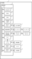
図2は、第1の実施形態の制御装置2の機能の一例を示すブロック図である。制御装置2は、記憶部221と、残り時間算出部222と、温度情報受付部223と、運転時間算出部224と、冷却制御部225とを備えている。
記憶部221は、例えば、各種情報がRAM204または不揮発性メモリ205に記憶されることにより実現される。残り時間算出部222、温度情報受付部223、運転時間算出部224、および冷却制御部225は、例えば、ハードウェアプロセッサ201が、ROM203に記憶されたシステムプログラム、および不揮発性メモリ205に記憶された各種データを用いて演算処理することにより実現される。
記憶部221は、例えば、動作プログラム、モータ情報、機械情報、熱モデル、および運転可能時間算出式を記憶する。動作プログラムは、産業機械1を動作させるためのプログラムである。動作プログラムは、例えば、工作機械の加工プログラムである。加工プログラムは、例えば、主軸の回転数を指定する指令、各軸の送り速度を指定する指令、および座標値を用いた各軸の移動指令を含む。
モータ情報は、モータに関する情報である。モータ情報は、モータの抵抗値、モータの熱容量、モータの鉄損発熱係数、およびモータの仕様に関する情報を含む。モータの仕様に関する情報は、モータの定格電流、始動トルク、始動電流などを示す情報を含んでいてよい。鉄損発熱係数については、後述する。
機械情報は、産業機械1に関する情報である。機械情報は、産業機械1の仕様に関する情報を含んでいてよい。機械情報は、例えば、工作機械のテーブルなど、各軸に沿って動作する産業機械1の構造物の重量を示す情報を含む。また、機械情報は、産業機械1の各構造物が各軸に沿って移動する際に生じる摩擦力に関する情報を含んでいてもよい。
機械情報は、例えば、ロボットのアームなど、各軸周りに回転する産業機械1の構造物の重量を示す情報を含んでいてもよい。機械情報は、産業機械1の各構造物が各軸に周りに回転する際に生じる摩擦力に関する情報を含んでいてもよい。
熱モデルは、動作プログラムが実行されたときのモータの動作と発熱能力との関係を示す数式である。熱モデルは、例えば、次の数1式で表される。

ただし、Hmはモータの発熱能力、Iはモータの二乗平均電流値、Rはモータの抵抗値、Nはモータの二乗平均回転数、Hは鉄損発熱係数である。
モータの発熱能力は、当該発熱能力の算出時点から基準時までにモータが発生させる熱量の推定値である。基準時は、例えば、実行中の動作プログラムの終了時である。基準時は、例えば、動作プログラムのオプショナルストップが実行される時点であってもよい。
モータの二乗平均電流値は、当該二乗平均電流値の算出時点から基準時までの間の各時刻のモータの電流値の二乗の平均を示す値である。二乗平均電流値は、動作プログラム、モータ情報、および機械情報に基づいて算出される。
例えば、二乗平均電流値の算出には、動作プログラムで指定されるモータ回転数、各軸の送り速度、および各軸の移動距離が用いられる。また、二乗平均電流値の算出には、動作プログラムに基づいて算出される値が用いられてもよい。動作プログラムに基づいて算出される値は、例えば、各軸の加速度である。
モータの二乗平均電流値の算出には、さらに、モータの定格電流、およびモータの始動トルクなどのモータの仕様に関する情報が用いられてもよい。
モータの二乗平均電流値の算出には、工作機械のテーブルの重量などの機械の仕様に関する情報が用いられる。また、モータの二乗平均電流値の算出には、テーブルなどの構造物が各軸に沿って移動する際に生じる摩擦力に関する情報が用いられてもよい。
モータの抵抗値は、モータの巻線の抵抗を示す値である。モータの抵抗値は、あらかじめ計測された値、または、モータの設計情報が示す値である。
モータの二乗平均回転数は、当該二乗平均回転数の算出時点から基準時までの間の各時刻のモータの回転数の二乗の平均を示す値である。二乗平均回転数は、動作プログラムで指定された指令値に基づいて算出される。
鉄損発熱係数は、モータが所定の回転動作を行ったときの、モータの二乗平均回転数に対するモータの発熱量の割合を示す値である。鉄損発熱係数は、あらかじめ実験によって求められてよい。あるいは、鉄損発熱係数は、設計情報が示す値であってもよい。
運転可能時間算出式は、モータの運転可能時間を算出するための数式である。運転可能時間は、当該運転可能時間の算出時点からモータが目標温度に到達するまでの時間である。
運転可能時間は、運転可能時間の算出時点の冷却装置10の冷却能力を維持させたと仮定した場合にモータが過熱状態に達するまでの時間として算出される。運転可能時間算出式は、例えば、以下の数2式で表される。
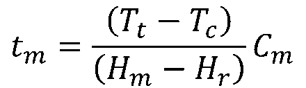
ただし、tmは運転可能時間、Ttは目標温度、Tcは現在の温度、Hmはモータの発熱能力、Hrはモータの冷却能力、Cmはモータの熱容量である。
目標温度Ttは、動作プログラムが実行された場合にモータの到達目標となる温度である。目標温度Ttは、例えば、モータが過熱状態に達する温度である。すなわち、目標温度Ttは、モータの許容上限温度である。モータの目標温度Ttは、例えば、100[℃]である。モータの目標温度Ttは、あらかじめ記憶部221に記憶されていてよい。
現在の温度Tcは、運転可能時間の算出時におけるモータの温度である。すなわち、現在の温度Tcは、モータの温度に関する温度情報である。現在の温度Tcは、センサ9によって取得される。
モータの冷却能力Hrは、モータを冷却する能力を示す値である。モータの冷却能力Hrは、自冷、空冷、および水冷に応じて異なる。冷却能力Hrは、自冷、空冷、および水冷に応じてそれぞれ、数3式、数4式および数5式で表される。モータの冷却能力Hrは、あらかじめ、記憶部221に記憶される。

ただし、J1は自冷時のモータの除熱係数、TEはモータが設置されている環境の温度である。

ただし、J2は空冷時の除熱係数、Sfは冷却装置10の冷却ファンの回転数である。

ただし、J3は水冷時の除熱係数、Qは冷却液の流量である。
モータの熱容量Cmはモータの温度を1℃上昇させるために必要な熱量である。モータの熱容量Cmは、あらかじめ測定されて記憶部221に記憶される。
残り時間算出部222は、動作プログラムを解析して基準時までの残り時間を算出する。すなわち、残り時間は、残り時間の算出時点から基準時までの間の時間である。残り時間算出部222は、動作プログラムの各軸の移動指令、および送り速度を指定する指令などに基づいて残り時間を算出する。
残り時間算出部222は、動作プログラムの実行開始時および動作プログラムの実行中に基準時までの時間を算出する。残り時間算出部222は、例えば、動作プログラムの実行中に、10[s]ごとに残り時間を算出する。
温度情報受付部223は、センサ9によって検出されたモータの温度に関する温度情報をセンサ9から受け付ける。モータは、例えば、スピンドルモータ7、およびサーボモータ5である。モータは、産業機械1が備えるリニアモータであってもよい。温度情報受付部223は、例えば、制御装置2の制御周期ごとにセンサ9から温度情報を受け付ける。
運転時間算出部224は、少なくとも、センサ9によって検出された温度に関する温度情報、動作プログラム、およびモータの熱モデルに基づいて、モータの運転可能時間を算出する。運転時間算出部224は、例えば、上述した運転可能時間算出式を用いてモータの運転可能時間を算出する。この場合、運転時間算出部224は、記憶部221に記憶された情報などを運転可能時間算出式に代入し、運転可能時間を算出する。
運転時間算出部224は、例えば、モータの抵抗値、鉄損発熱係数、目標温度、およびモータの熱容量を用いて運転可能時間を算出する。また、運転時間算出部224は、算出されたモータの発熱能力、およびモータの温度に関する温度情報を用いて運転可能時間を算出する。
なお、運転時間算出部224は、上述した運転可能時間算出式に限らず、他の式を用いてもよい。また、運転可能時間算出式には、モータの抵抗値、鉄損発熱係数、目標温度、モータの熱容量などの情報があらかじめ組み込まれていてもよい。この場合、運転時間算出部224は、運転可能時間の算出時に記憶部221からこれらの情報を読み出す必要がない。
冷却制御部225は、残り時間算出部222によって算出された残り時間と、運転時間算出部224によって算出された運転可能時間とに基づいて、モータを冷却する冷却装置10を制御する。冷却制御部225は、冷却装置10の運転を開始または冷却装置10の運転を停止させる制御を行う。この場合、冷却装置10の冷却能力は、あらかじめ定められた一定の能力であってよい。
冷却制御部225は、まず、残り時間と運転可能時間とを比較する。冷却制御部225は、比較結果に基づいて冷却装置10を制御する。
冷却装置10が運転中であって残り時間が運転可能時間よりも短い場合、冷却制御部225は、冷却装置10の運転を停止させる。また、冷却装置10の運転が停止中であって残り時間が運転可能時間よりも短い場合、冷却制御部225は冷却装置10の停止状態を継続させる。
冷却装置10が運転中であって残り時間と運転可能時間が同じである場合、冷却制御部225は、冷却装置10の運転を継続させる。冷却装置10が停止中であって残り時間と運転可能時間が同じである場合、冷却制御部225は、冷却装置10の停止状態を維持させる。
冷却装置10が停止中であって残り時間が運転可能時間よりも長い場合、冷却制御部225は、冷却装置10の運転を開始させる。
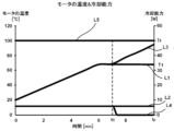
図3は、モータの温度の推移などを示すグラフの一例である。L1は、従来のモータの冷却方法に基づいてモータの冷却が行われた場合のモータの温度の推移を示す。L2は、従来のモータの冷却方法に基づいてモータの冷却が行われた場合の冷却装置10の冷却能力の推移を示す。L3は、本実施形態における冷却方法に基づいてモータの冷却が行われた場合のモータの温度の推移を示す。L4は本実施形態における冷却方法に基づいてモータの冷却が行われた場合の冷却装置10の冷却能力の推移を示す。L5はモータの目標温度Ttを示す。
L1およびL2が示すように、従来の冷却方法では、モータがある温度T1に達すると動作プログラムの実行が終了する基準時tcまでモータの温度はその温度T1に維持される。しかし、この温度T1は、目標温度Ttよりもかなり低い温度である。すなわち、従来の冷却方法では、モータが過剰に冷却されているといえる。
一方、L3およびL4が示すように、本実施形態における冷却方法では、冷却制御部225は、時間t1において冷却装置10の運転を停止させている。冷却制御部225が時間t1において、残り時間と運転可能時間とを比較して残り時間が運転可能時間よりも短いと判断したからである。これにより、本実施形態における冷却方法では、モータが過剰に冷却されることを防いでいる。その結果、冷却装置10で消費されるエネルギーが節約される。
図4は、制御装置2で実行される処理の流れの一例を示すフローチャートである。制御装置2では、まず、残り時間算出部222が動作プログラムを解析して基準時までの残り時間を算出する(ステップSA1)。例えば、動作プログラムの実行が開始されてから所定時間が経過した時点において、残り時間算出部222は、残り時間を、600[s]であると算出する。
次に、温度情報受付部223がセンサ9によって検出されたモータの温度に関する温度情報を受け付ける(ステップSA2)。温度情報受付部223は、例えば、モータの温度が20[℃]であることを示す温度情報を受け付ける。
次に、運転時間算出部224が、少なくとも、温度情報、動作プログラム、および熱モデルに基づいて、モータの運転可能時間を算出する(ステップSA3)。運転時間算出部224は、例えば、残り時間である600[s]の間のモータの二乗平均電流、およびモータの二乗平均回転数などを示す情報に基づいて、モータが、毎秒0.2[℃]の速さで温度が上昇することを算出する。目標温度が100[℃]である場合、運転時間算出部224は、運転可能時間を、例えば、400[s]であると算出する。
最後に、冷却制御部225が、残り時間算出部222によって算出された残り時間と、運転時間算出部224によって算出された運転可能時間とに基づいて、モータを冷却する冷却装置10を制御する(ステップSA4)。例えば、残り時間が600[s]、運転可能時間が400[s]である場合は、残り時間が運転可能時間よりも長いため、冷却装置10の運転を停止させることができない。この場合、冷却制御部225は、冷却装置10の運転を継続させる。
ステップSA1~ステップSA4までの処理は、例えば、動作プログラムの実行中に所定時間ごとに繰り返し実行される。この所定時間は、上述したように、例えば、10[s]である。
例えば、残り時間が180[s]の時点において、温度情報受付部223は、モータの温度が66[℃]であることを示す温度情報を受け付ける(ステップSA2)。また、運転時間算出部224は、モータが、毎秒0.18[℃]の速さで上昇することを算出する(ステップSA3)。この場合、目標温度である100[℃]にモータの温度が到達するまでに、188[s]の時間を要する。すなわち、運転可能時間が188[s]である。すなわち、残り時間である180[s]は運転可能時間である188[s]よりも短いため、冷却制御部225は、冷却装置10の運転を停止させ(ステップSA4)、当該処理が終了する。
〈第2の実施形態〉
図5は、第2の実施形態の制御装置2の機能の一例を示すブロック図である。第2の実施形態の制御装置2は、第1の実施形態の制御装置2が備える機能に加え、さらに、冷却情報受付部226を備える。冷却情報受付部226は、例えば、ハードウェアプロセッサ201が、ROM203に記憶されているシステムプログラム、および不揮発性メモリ205に記憶されている各種データを用いて演算処理することにより実現される。
図5は、第2の実施形態の制御装置2の機能の一例を示すブロック図である。第2の実施形態の制御装置2は、第1の実施形態の制御装置2が備える機能に加え、さらに、冷却情報受付部226を備える。冷却情報受付部226は、例えば、ハードウェアプロセッサ201が、ROM203に記憶されているシステムプログラム、および不揮発性メモリ205に記憶されている各種データを用いて演算処理することにより実現される。
冷却情報受付部226は、冷却装置10の冷却能力を示す冷却情報を受け付ける。冷却能力を示す冷却情報は、例えば、モータが空冷によって冷却されるか、または水冷によって冷却されるかを示す情報を含む。
モータが空冷によって冷却される場合、冷却能力を示す冷却情報は、空冷時の除熱係数J2、および冷却装置10のファンの回転数Sfを含む。すなわち、冷却情報は、上述した数4式で表される。
モータが水冷によって冷却される場合、冷却能力を示す冷却情報は、水冷時のモータの除熱係数J3、および冷却液の流量Qを含む。すなわち、冷却情報は、上述した数5式で表される。
運転時間算出部224は、さらに、冷却情報受付部226が受け付けた冷却情報に基づいて、運転可能時間を算出する。すなわち、運転時間算出部224は、少なくとも、センサ9によって検出されたモータの温度に関する温度情報、動作プログラム、熱モデル、および、冷却情報に基づいて運転可能時間を算出する。
冷却制御部225は、まず、残り時間算出部222によって算出された残り時間と運転時間算出部224によって算出された運転可能時間とを比較する。冷却制御部225は、比較結果に基づいて冷却装置10を制御する。この場合、冷却制御部225は、冷却装置10の冷却能力を向上または低下させる制御を行う。
冷却装置10が運転中であって残り時間が運転可能時間よりも短い場合、冷却制御部225は、冷却装置10の冷却能力を低下させる。すなわち、冷却制御部225は、冷却装置10の冷却ファンの回転数を下げ、冷却装置10の冷却液の流量を減らし、または、冷却装置10の運転を停止させる。
冷却装置10が運転中であって残り時間が運転可能時間よりも長い場合、冷却制御部225は、冷却装置10の冷却能力を向上させる。すなわち、冷却制御部225は、冷却装置10の冷却ファンの回転数を上げ、冷却装置10の冷却液の流量を増やす。
冷却装置10が運転中であって残り時間と運転可能時間とが同じである場合、冷却制御部225は、冷却装置10の運転を継続させる。この場合、冷却制御部225は冷却装置10の冷却能力を維持させる。すなわち、冷却制御部225は、冷却装置10の冷却ファンの回転数を維持させ、または、冷却装置10の冷却液の流量を維持させる。
冷却装置10の運転が停止中であって残り時間と運転可能時間が同じである場合、冷却制御部225は、冷却装置10の停止状態を維持させる。
冷却装置10の運転が停止中であって残り時間が運転可能時間よりも長い場合、冷却制御部225は、冷却装置10の冷却能力を向上させる。すなわち、冷却制御部225は、冷却装置10の運転を開始させる。
冷却装置10の運転が停止中であって残り時間が運転可能時間よりも短い場合、冷却制御部225は、冷却装置10の運転の停止状態を維持させる。
図6は、モータの温度の推移などを示すグラフの一例である。L11は、従来のモータの冷却方法に基づいてモータの冷却が行われた場合のモータの温度の推移を示す。L12は、従来のモータの冷却方法に基づいてモータの冷却が行われた場合の冷却装置10の冷却能力の推移を示す。L13は、従来のモータの冷却方法においてあらかじめ設定された設定温度TSを示している。L14は、目標温度Ttを示す。L15は、本実施形態における冷却方法に基づいてモータの冷却が行われた場合のモータの温度の推移を示す。L16は、本実施形態における冷却方法に基づいてモータの冷却が行われた場合の冷却装置10の冷却能力の推移を示す。
L11、L12およびL13が示すように、従来のモータの冷却方法では、モータの温度が設定温度TSに達したタイミングt12において、冷却装置10の運転が開始されている。しかし、冷却装置10の運転が開始されたタイミングt12とモータの温度が低下し始めるタイミングとの間にはタイムラグが生じる。そのため、モータが設定温度TSに達したあとに冷却装置10の運転が開始されても、モータの温度は上昇して目標温度Ttに到達してしまう。
一方、本実施形態のモータの冷却方法では、動作プログラムの実行が開始されてから所定の時間が経過したタイミングt11において、冷却制御部225が冷却装置10の冷却能力を向上させている。図6に示す例では、冷却装置10の冷却能力は、10[W]まで向上している。冷却制御部225は、冷却情報受付部226が受け付けた冷却情報に基づいて、運転可能時間が残り時間よりもわずかに長くなるように冷却能力を向上させる。そのため、本実施形態の冷却方法では、動作プログラムの実行が終了する基準時tcまでに、モータの温度は目標温度Ttに到達しない。
図7は、制御装置2で実行される処理の流れの一例を示すフローチャートである。制御装置2では、まず、残り時間算出部222が動作プログラムを解析して基準時までの残り時間を算出する(ステップSB1)。例えば、動作プログラムの実行が開始されてから所定時間が経過した時点において、残り時間算出部222は、残り時間を、600[s]であると算出する。
次に、温度情報受付部223がセンサ9によって検出されたモータの温度に関する温度情報を受け付ける(ステップSB2)。温度情報受付部223は、例えば、モータの温度が20[℃]であることを示す温度情報を受け付ける。
次に、冷却情報受付部226が、冷却装置10の冷却能力を示す冷却情報を受け付ける(ステップSB3)。冷却情報受付部226は、例えば、空冷時の除熱係数J2と、冷却ファンの回転数が600[rpm]であることを示す情報を受け付ける。
次に、運転時間算出部224が、少なくとも、温度情報、動作プログラム、熱モデル、および冷却情報に基づいて、モータの運転可能時間を算出する(ステップSB4)。運転時間算出部224は、例えば、残り時間である600[s]の間のモータの二乗平均電流、およびモータの二乗平均回転数などを示す情報に基づいて、モータが、毎秒0.2[℃]の速さで温度が上昇することを算出する。目標温度が100[℃]である場合、運転時間算出部224は、運転可能時間を、例えば、400[s]であると算出する。
最後に、冷却制御部225が、残り時間算出部222によって算出された残り時間と、運転時間算出部224によって算出された運転可能時間とに基づいて、モータを冷却する冷却装置10を制御する(ステップSB5)。例えば、残り時間が600[s]、運転可能時間が400[s]である場合は、残り時間が運転可能時間よりも長いため、冷却装置10の冷却能力が不足している。この場合、冷却制御部225は、冷却装置10の冷却能力を向上させる。
冷却制御部225は、例えば、運転可能時間が600[s]以上となるように、冷却装置10の冷却能力を算出する(ステップSB4)。冷却制御部225は、運転可能時間が600[s]以上となるための冷却ファンの回転数を、例えば、1000[rpm]であると算出する。冷却制御部225は、算出した冷却ファンの回転数に基づいて、冷却ファンを制御する(ステップSB5)。
なお、ステップSB1~ステップSB5までの処理は、例えば、プログラムの実行中に所定時間ごとに繰り返し実行される。この所定時間は、上述したように、例えば、10[s]である。
〈第3の実施形態〉
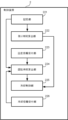
図8は、第3の実施形態の制御装置2の機能の一例を示すブロック図である。第3の実施形態の制御装置2は、第2の実施形態の制御装置2が備える機能に加え、さらに、入力受付部227を備える。入力受付部227は、例えば、ハードウェアプロセッサ201が、ROM203に記憶されているシステムプログラム、および不揮発性メモリ205に記憶されている各種データを用いて演算処理することにより実現される。
図8は、第3の実施形態の制御装置2の機能の一例を示すブロック図である。第3の実施形態の制御装置2は、第2の実施形態の制御装置2が備える機能に加え、さらに、入力受付部227を備える。入力受付部227は、例えば、ハードウェアプロセッサ201が、ROM203に記憶されているシステムプログラム、および不揮発性メモリ205に記憶されている各種データを用いて演算処理することにより実現される。
入力受付部227は、制御装置2の外部から入力される入力情報を受け付ける。入力受付部227は、例えば、入出力装置3からの入力情報を受け付ける。入力情報は、例えば、モータの目標温度Ttである。
入力受付部227が、例えば、モータの目標温度Ttを受け付けた場合、運転時間算出部224は、さらに、入力受付部227が受け付けた入力情報に基づいて、運転可能時間を算出する。すなわち、運転時間算出部224は、温度情報、動作プログラム、熱モデル、冷却情報、および目標温度Ttに基づいて運転可能時間を算出する。
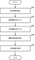
図9は、制御装置2で実行される処理の流れの一例を示す。制御装置2では、まず、残り時間算出部222が動作プログラムを解析して基準時までの残り時間を算出する(ステップSC1)。
次に、温度情報受付部223がセンサ9によって検出されたモータの温度に関する温度情報を受け付ける(ステップSC2)。
次に、入力受付部227が入力情報の入力を受け付ける(ステップSC3)。
次に、冷却情報受付部226が、冷却装置10の冷却能力を示す冷却情報を受け付ける(ステップSC4)。
次に、運転時間算出部224が、少なくとも、温度情報、動作プログラム、冷却情報、および入力情報に基づいて、モータの運転可能時間を算出する(ステップSC5)。
最後に、冷却制御部225が、残り時間算出部222によって算出された残り時間と、運転時間算出部224によって算出された運転可能時間とに基づいて、モータを冷却する冷却装置10を制御して(ステップSC6)、当該処理が終了する。
なお、ステップSC1~ステップSC6までの処理は、例えば、プログラムの実行中に所定時間ごとに繰り返し実行される。
上述したように、冷却制御部225は、冷却装置10を停止させる制御、または、冷却装置10の冷却能力を低下させる制御を行う場合がある。この場合、冷却制御部225は、冷却装置10を停止させる制御、または、冷却装置10の冷却能力を低下させる制御を行わない場合と比較して節約されたエネルギーを算出してもよい。
冷却制御部225は、例えば、図3に示す例において、従来の冷却方法において冷却装置10が消費するエネルギーと第1の実施形態の冷却方法において冷却装置10が消費するエネルギーの差分を算出してもよい。この差分が節約されたエネルギーとなる。この場合、制御装置2は、例えば、節約されたエネルギーを示す情報を入出力装置3に表示させてもよい。
上述した各実施形態では、1つの動作プログラムが実行される場合のモータの冷却方法について説明した。しかし、複数の動作プログラムが、機械停止期間を挟んで実行される場合であっても、本開示の冷却方法が適用されてもよい。この場合、運転時間算出部224は、温度情報、実行中の動作プログラムに加え、さらに、動作プログラムが実行されていない機械停止期間を加味して運転可能時間を算出する。
図10は、モータの温度の推移などを示すグラフの一例である。図10に示す例では、第1の動作プログラムが実行される第1の期間と、第1の期間の後に、第2の動作プログラムが実行される第2の期間と、第1の期間と第2の期間との間に動作プログラムが実行されない機械停止期間が設けられる。
L21は、従来のモータの冷却方法に基づいてモータの冷却が行われた場合のモータの温度の推移を示す。L22は、従来のモータの冷却方法に基づいてモータの冷却が行われた場合の冷却装置10の冷却能力の推移を示す。L23は、目標温度Ttを示す。L24は、本実施形態の冷却方法に基づいてモータの冷却が行われた場合のモータの温度の推移を示す。L25は、本実施形態の冷却方法に基づいてモータの冷却が行われた場合のモータの冷却能力の推移を示す。
L21およびL22が示すように、従来のモータの冷却方法では、冷却装置10の冷却能力は、第1の期間、機械停止期間、および第2の期間を通して一定に保たれている。この場合、モータの温度は、第1の期間では上昇する。また、モータの温度は、機械停止期間では低下する。また、モータの温度は、第2の期間では上昇して目標温度に達する。
一方、本実施形態の冷却方法では、第1の動作プログラムの実行開始から所定時間が経過したタイミングt21において、運転時間算出部224が運転可能時間を算出する。運転時間算出部224は、所定時間が経過したタイミングt21における冷却装置10の冷却能力に基づいて、運転可能時間を算出する。
ここで、運転可能時間は、制御装置2において、第1の動作プログラムが実行された後に、所定の機械停止期間が設けられ、その後、第2の動作プログラムが実行される場合における運転可能時間である。
運転時間算出部224は、まず、タイミングt21において、例えば、上述した数2式などを用いて、第1の期間の終了時におけるモータの温度を算出する。さらに、運転時間算出部224は、例えば、第1の期間の終了時におけるモータの温度、および上述した数2式用いて、機械停止期間の終了時におけるモータの温度を算出する。さらに、運転時間算出部224は、機械停止期間の終了時におけるモータの温度、第2の動作プログラム、および熱モデルに基づいて、第2の期間における運転可能時間を算出する。運転時間算出部224は、第1の期間と、機械停止期間と、第2の期間における運転可能時間とを加算することにより、第1の動作プログラムが実行された後に、所定の機械停止期間が設けられ、その後、第2の動作プログラムが実行される場合における運転可能時間を算出する。
そして、残り時間算出部222によって算出された残り時間が運転可能時間よりも長い場合、冷却制御部225は、冷却装置10の冷却能力を向上させる。冷却制御部225は、基準時、すなわち、第2の動作プログラムの終了時におけるモータの温度が目標温度に達しないように冷却装置10の冷却能力を向上させる。
以上説明したように、制御装置2は、動作プログラムを解析して基準時までの残り時間を算出する残り時間算出部222と、センサ9によって検出されたモータの温度に関する温度情報を受け付ける温度情報受付部223と、少なくとも、温度情報、動作プログラム、および熱モデルに基づいて、モータの運転可能時間を算出する運転時間算出部224と、残り時間算出部222によって算出された残り時間と、運転時間算出部224によって算出された運転可能時間とに基づいて、モータを冷却する冷却装置10を制御する冷却制御部225と、を備える。
したがって、制御装置2は、冷却装置10が必要以上にエネルギーを消費すること、および、モータが過熱することを防ぐことが可能となる。
また、制御装置2は、冷却装置10の冷却能力を示す冷却情報を受け付ける冷却情報受付部226をさらに備え、運転時間算出部224は、さらに、冷却情報受付部226が受け付けた冷却情報に基づいて、運転可能時間を算出する。また、冷却制御部225は、冷却装置10の運転を開始または停止させる制御、もしくは、冷却装置10の冷却能力を向上または低下させる制御を行う。
したがって、制御装置2は、冷却装置10の現在の冷却能力に基づいて、冷却装置10を適切に制御することができる。その結果、制御装置2は、冷却装置10が必要以上にエネルギーを消費すること、および、モータが過熱することをさらに効果的に防ぐことができる。
また、冷却制御部225は、冷却装置10を停止させる制御、または、冷却装置10の冷却能力を低下させる制御を行う場合、冷却装置10を停止させる制御、または、冷却装置10の冷却能力を低下させる制御を行わない場合と比較して節約されたエネルギーを算出する。この場合、制御装置2は、例えば、入出力装置3に節約されたエネルギーを表示させることができる。
また、モータの目標温度の入力を受け付ける入力受付部227をさらに備え、運転時間算出部224は、さらに、入力受付部227によって受け付けられた目標温度に基づいて、運転可能時間を算出する。したがって、オペレータは、モータの仕様に合わせて、モータの目標温度を入力することができる。また、オペレータは、目標温度を容易に変更することができる。
また、基準時は、動作プログラムの終了時である。したがって、制御装置2は、動作プログラムの終了時までにモータが過熱状態になることを防ぐことができる。
また、運転時間算出部224は、さらに、動作プログラムが実行されていない機械停止期間を示す情報に基づいて、運転可能時間を算出する。したがって、制御装置2は、複数の動作プログラムが連続して、または機械停止期間をあけて実行される場合であっても、冷却装置10が必要以上にエネルギーを消費すること、および、モータが過熱することをさらに効果的に防ぐことができる。
本開示について詳述したが、本開示は上述した個々の実施形態に限定されるものではない。これらの実施形態は、本開示の要旨を逸脱しない範囲で、または、請求の範囲に記載された内容とその均等物から導き出される本開示の要旨を逸脱しない範囲で、種々の追加、置き換え、変更、部分的削除等が可能である。また、これらの実施形態は、組み合わせて実施することもできる。
以下に、本開示の実施形態に係る付記を示す。
付記[1]
動作プログラムを解析して基準時までの残り時間を算出する残り時間算出部と、センサによって検出されたモータの温度に関する温度情報を受け付ける温度情報受付部と、少なくとも、前記温度情報、前記動作プログラム、および熱モデルに基づいて、前記モータの運転可能時間を算出する運転時間算出部と、前記残り時間算出部によって算出された前記残り時間と、前記運転時間算出部によって算出された前記運転可能時間とに基づいて、前記モータを冷却する冷却装置を制御する冷却制御部と、を備える制御装置。
付記[2]
前記冷却装置の冷却能力を示す冷却情報を受け付ける冷却情報受付部をさらに備え、前記運転時間算出部は、さらに、前記冷却情報受付部が受け付けた前記冷却情報に基づいて、前記運転可能時間を算出する付記[1]に記載の制御装置。
付記[3]
前記冷却制御部は、前記冷却装置の運転を開始または前記冷却装置の運転を停止させる制御、もしくは、前記冷却装置の冷却能力を向上または低下させる制御を行う付記[1]または[2]に記載の制御装置。
付記[4]
前記冷却制御部は、前記冷却装置を停止させる制御、または、前記冷却装置の冷却能力を低下させる制御を行う場合、前記冷却装置を停止させる制御、または、前記冷却装置の冷却能力を低下させる制御を行わない場合と比較して節約されたエネルギーを算出する付記[3]に記載の制御装置。
付記[5]
前記モータの目標温度の入力を受け付ける入力受付部をさらに備え、前記運転時間算出部は、さらに、前記入力受付部によって受け付けられた前記目標温度に基づいて、前記運転可能時間を算出する付記[1]~[4]のいずれかに記載の制御装置。
付記[6]
前記基準時は、前記動作プログラムの終了時である付記[1]~[5]のいずれかに記載の制御装置。
付記[7]
前記運転時間算出部は、さらに、前記動作プログラムが実行されていない機械停止期間を示す情報に基づいて、前記運転可能時間を算出する付記[1]~[6]のいずれかに記載の制御装置。
付記[1]
動作プログラムを解析して基準時までの残り時間を算出する残り時間算出部と、センサによって検出されたモータの温度に関する温度情報を受け付ける温度情報受付部と、少なくとも、前記温度情報、前記動作プログラム、および熱モデルに基づいて、前記モータの運転可能時間を算出する運転時間算出部と、前記残り時間算出部によって算出された前記残り時間と、前記運転時間算出部によって算出された前記運転可能時間とに基づいて、前記モータを冷却する冷却装置を制御する冷却制御部と、を備える制御装置。
付記[2]
前記冷却装置の冷却能力を示す冷却情報を受け付ける冷却情報受付部をさらに備え、前記運転時間算出部は、さらに、前記冷却情報受付部が受け付けた前記冷却情報に基づいて、前記運転可能時間を算出する付記[1]に記載の制御装置。
付記[3]
前記冷却制御部は、前記冷却装置の運転を開始または前記冷却装置の運転を停止させる制御、もしくは、前記冷却装置の冷却能力を向上または低下させる制御を行う付記[1]または[2]に記載の制御装置。
付記[4]
前記冷却制御部は、前記冷却装置を停止させる制御、または、前記冷却装置の冷却能力を低下させる制御を行う場合、前記冷却装置を停止させる制御、または、前記冷却装置の冷却能力を低下させる制御を行わない場合と比較して節約されたエネルギーを算出する付記[3]に記載の制御装置。
付記[5]
前記モータの目標温度の入力を受け付ける入力受付部をさらに備え、前記運転時間算出部は、さらに、前記入力受付部によって受け付けられた前記目標温度に基づいて、前記運転可能時間を算出する付記[1]~[4]のいずれかに記載の制御装置。
付記[6]
前記基準時は、前記動作プログラムの終了時である付記[1]~[5]のいずれかに記載の制御装置。
付記[7]
前記運転時間算出部は、さらに、前記動作プログラムが実行されていない機械停止期間を示す情報に基づいて、前記運転可能時間を算出する付記[1]~[6]のいずれかに記載の制御装置。
1 産業機械
2 制御装置
201 ハードウェアプロセッサ
202 バス
203 ROM
204 RAM
205 不揮発性メモリ
206 第1のインタフェース
207 軸制御回路
208 スピンドル制御回路
209 PLC
210 I/Oユニット
211 第2のインタフェース
212 第3のインタフェース
221 記憶部
222 残り時間算出部
223 温度情報受付部
224 運転時間算出部
225 冷却制御部
226 冷却情報受付部
227 入力受付部
3 入出力装置
4 サーボアンプ
5 サーボモータ
6 スピンドルアンプ
7 スピンドルモータ
8 補助機器
9 センサ
10 冷却装置
2 制御装置
201 ハードウェアプロセッサ
202 バス
203 ROM
204 RAM
205 不揮発性メモリ
206 第1のインタフェース
207 軸制御回路
208 スピンドル制御回路
209 PLC
210 I/Oユニット
211 第2のインタフェース
212 第3のインタフェース
221 記憶部
222 残り時間算出部
223 温度情報受付部
224 運転時間算出部
225 冷却制御部
226 冷却情報受付部
227 入力受付部
3 入出力装置
4 サーボアンプ
5 サーボモータ
6 スピンドルアンプ
7 スピンドルモータ
8 補助機器
9 センサ
10 冷却装置
Claims (7)
- 動作プログラムを解析して基準時までの残り時間を算出する残り時間算出部と、
センサによって検出されたモータの温度に関する温度情報を受け付ける温度情報受付部と、
前記動作プログラム、前記温度情報、および前記モータの熱モデルに基づいて、前記モータの運転可能時間を算出する運転時間算出部と、
前記残り時間算出部によって算出された前記残り時間と、前記運転時間算出部によって算出された前記運転可能時間とに基づいて、前記モータを冷却する冷却装置を制御する冷却制御部と、
を備える制御装置。 - 前記冷却装置の冷却能力を示す冷却情報を受け付ける冷却情報受付部をさらに備え、
前記運転時間算出部は、さらに、前記冷却情報受付部が受け付けた前記冷却情報に基づいて、前記運転可能時間を算出する請求項1に記載の制御装置。 - 前記冷却制御部は、前記冷却装置の運転を開始または停止させる制御、もしくは、前記冷却装置の冷却能力を向上または低下させる制御を行う請求項1または2に記載の制御装置。
- 前記冷却制御部は、前記冷却装置を停止させる制御、または、前記冷却装置の冷却能力を低下させる制御を行う場合、前記冷却装置を停止させる制御、または、前記冷却装置の冷却能力を低下させる制御を行わない場合と比較して節約されたエネルギーを算出する請求項3に記載の制御装置。
- 前記モータの目標温度の入力を受け付ける入力受付部をさらに備え、
前記運転時間算出部は、さらに、前記入力受付部によって受け付けられた前記目標温度に基づいて、前記運転可能時間を算出する請求項1~4のいずれか1項に記載の制御装置。 - 前記基準時は、前記動作プログラムの終了時である請求項1~5のいずれか1項に記載の制御装置。
- 前記運転時間算出部は、さらに、前記動作プログラムが実行されていない機械停止期間を示す情報に基づいて、前記運転可能時間を算出する請求項1~6のいずれか1項に記載の制御装置。
Priority Applications (2)
| Application Number | Priority Date | Filing Date | Title |
|---|---|---|---|
| PCT/JP2022/044044 WO2024116296A1 (ja) | 2022-11-29 | 2022-11-29 | 冷却装置を制御する制御装置 |
| JP2024561034A JPWO2024116296A1 (ja) | 2022-11-29 | 2022-11-29 |
Applications Claiming Priority (1)
| Application Number | Priority Date | Filing Date | Title |
|---|---|---|---|
| PCT/JP2022/044044 WO2024116296A1 (ja) | 2022-11-29 | 2022-11-29 | 冷却装置を制御する制御装置 |
Publications (1)
| Publication Number | Publication Date |
|---|---|
| WO2024116296A1 true WO2024116296A1 (ja) | 2024-06-06 |
Family
ID=91323395
Family Applications (1)
| Application Number | Title | Priority Date | Filing Date |
|---|---|---|---|
| PCT/JP2022/044044 Ceased WO2024116296A1 (ja) | 2022-11-29 | 2022-11-29 | 冷却装置を制御する制御装置 |
Country Status (2)
| Country | Link |
|---|---|
| JP (1) | JPWO2024116296A1 (ja) |
| WO (1) | WO2024116296A1 (ja) |
Citations (3)
| Publication number | Priority date | Publication date | Assignee | Title |
|---|---|---|---|---|
| JP2000175348A (ja) * | 1998-12-04 | 2000-06-23 | Toshiba Corp | 電動機の制御装置 |
| JP2010074988A (ja) * | 2008-09-19 | 2010-04-02 | Toyota Motor Corp | インホイールモータの制御装置 |
| WO2020136765A1 (ja) * | 2018-12-26 | 2020-07-02 | 三菱電機株式会社 | 制御装置 |
-
2022
- 2022-11-29 WO PCT/JP2022/044044 patent/WO2024116296A1/ja not_active Ceased
- 2022-11-29 JP JP2024561034A patent/JPWO2024116296A1/ja active Pending
Patent Citations (3)
| Publication number | Priority date | Publication date | Assignee | Title |
|---|---|---|---|---|
| JP2000175348A (ja) * | 1998-12-04 | 2000-06-23 | Toshiba Corp | 電動機の制御装置 |
| JP2010074988A (ja) * | 2008-09-19 | 2010-04-02 | Toyota Motor Corp | インホイールモータの制御装置 |
| WO2020136765A1 (ja) * | 2018-12-26 | 2020-07-02 | 三菱電機株式会社 | 制御装置 |
Also Published As
| Publication number | Publication date |
|---|---|
| JPWO2024116296A1 (ja) | 2024-06-06 |
Similar Documents
| Publication | Publication Date | Title |
|---|---|---|
| US10434614B2 (en) | Control device for machine tool performing oscillation cutting | |
| JP3902710B2 (ja) | 数値制御による工作機械の制御方法及び装置 | |
| CN104508931B (zh) | 数控装置 | |
| JP4261470B2 (ja) | 制御装置 | |
| JP6490015B2 (ja) | 機械の冷却機構 | |
| JP6469171B2 (ja) | 電動機の制御装置 | |
| RU2009132423A (ru) | Нагрузочное сервоустройство топливного двигателя и способ поиска его динамической оптимизации | |
| US10088828B2 (en) | Controlling load ratio induced shut-down conditions in numerical control devices | |
| CN110402188B (zh) | 驱动系统和其评估 | |
| JP2853023B2 (ja) | 数値制御による機械装置の制御方法および装置 | |
| WO2024116296A1 (ja) | 冷却装置を制御する制御装置 | |
| KR960700126A (ko) | Cnc 작동식 공작 기계용 제어 장치(controller for cnc-operated ma-chine tools) | |
| JPH11245118A (ja) | ネジ加工制御装置 | |
| JP4282909B2 (ja) | 熱変位補正方法および熱変位補正係数の変更方法並びに同補正機能を有する数値制御装置 | |
| US20230361709A1 (en) | Estimation device for estimating drive state of electric motor disposed in machine tool | |
| JPH07266185A (ja) | Nc工作機械の切削液量制御装置 | |
| JPH06289917A (ja) | 推定外乱負荷トルクによるサーボモータ制御方法 | |
| KR20130083334A (ko) | 공작기계의 윤활유 제어 장치 및 그의 구동방법 | |
| JPH1080055A (ja) | モータのオーバヒート抑制制御方法 | |
| JP6904941B2 (ja) | 制御装置および制御方法 | |
| JP7846230B2 (ja) | 時間算出装置およびコンピュータ読み取り可能な記憶媒体 | |
| JPH0751992A (ja) | 穴開け加工方式 | |
| WO2024189813A1 (ja) | 数値制御装置およびコンピュータ読み取り可能な記憶媒体 | |
| JP7817362B2 (ja) | データ収集装置およびコンピュータ読み取り可能な記憶媒体 | |
| JP3283212B2 (ja) | 送り軸監視装置 |
Legal Events
| Date | Code | Title | Description |
|---|---|---|---|
| 121 | Ep: the epo has been informed by wipo that ep was designated in this application |
Ref document number: 22967130 Country of ref document: EP Kind code of ref document: A1 |
|
| WWE | Wipo information: entry into national phase |
Ref document number: 2024561034 Country of ref document: JP |
|
| NENP | Non-entry into the national phase |
Ref country code: DE |
|
| 122 | Ep: pct application non-entry in european phase |
Ref document number: 22967130 Country of ref document: EP Kind code of ref document: A1 |