WO2024116232A1 - 設定装置及び制御条件の決定方法 - Google Patents
設定装置及び制御条件の決定方法 Download PDFInfo
- Publication number
- WO2024116232A1 WO2024116232A1 PCT/JP2022/043736 JP2022043736W WO2024116232A1 WO 2024116232 A1 WO2024116232 A1 WO 2024116232A1 JP 2022043736 W JP2022043736 W JP 2022043736W WO 2024116232 A1 WO2024116232 A1 WO 2024116232A1
- Authority
- WO
- WIPO (PCT)
- Prior art keywords
- characteristic
- part change
- unit
- control
- motor
- Prior art date
- Legal status (The legal status is an assumption and is not a legal conclusion. Google has not performed a legal analysis and makes no representation as to the accuracy of the status listed.)
- Ceased
Links
Images









Classifications
-
- G—PHYSICS
- G05—CONTROLLING; REGULATING
- G05B—CONTROL OR REGULATING SYSTEMS IN GENERAL; FUNCTIONAL ELEMENTS OF SUCH SYSTEMS; MONITORING OR TESTING ARRANGEMENTS FOR SUCH SYSTEMS OR ELEMENTS
- G05B19/00—Program-control systems
- G05B19/02—Program-control systems electric
- G05B19/18—Numerical control [NC], i.e. automatically operating machines, in particular machine tools, e.g. in a manufacturing environment, so as to execute positioning, movement or co-ordinated operations by means of program data in numerical form
- G05B19/404—Numerical control [NC], i.e. automatically operating machines, in particular machine tools, e.g. in a manufacturing environment, so as to execute positioning, movement or co-ordinated operations by means of program data in numerical form characterised by control arrangements for compensation, e.g. for backlash, overshoot, tool offset, tool wear, temperature, machine construction errors, load, inertia
Definitions
- This disclosure relates to a setting device and a method for determining control conditions.
- Patent Document 1 discloses a management method that checks data for identifying the type and characteristics of the parts to be changed, data for maintenance management, and enables confirmation of the compatibility of the parts to be changed with the industrial machinery.
- the setting device disclosed herein is a setting device that sets control conditions for a numerical control device that controls the operation of an industrial machine having at least one electric motor, and includes a characteristic information acquisition unit that acquires characteristic information before and after a part is changed in the industrial machine, some of whose parts are changeable, a control condition determination unit that determines the control conditions for the numerical control device after the part is changed based on the characteristic information before and after the part is changed, and a setting unit that sets at least one of the control conditions determined by the control condition determination unit for the numerical control device that controls the operation of the industrial machine, some of whose parts are changeable.
- the control condition determination method disclosed herein is a method for determining control conditions of a numerical control device that controls the operation of an industrial machine having at least one electric motor, and for the industrial machine in which some of the parts are changeable, characteristic information before and after the part change is obtained, and the control conditions of the numerical control device after the part change are determined based on the characteristic information before and after the part change.
- FIG. 1 is a conceptual diagram showing a configuration of a machine tool control system 1 in a first embodiment.
- 1 is a block diagram showing the functional configuration of a machine tool 10 and a numerical control device 20.
- FIG. FIG. 2 is a block diagram showing a functional configuration of a setting device 30 according to the first embodiment.
- 11 is a conceptual diagram showing an example of acquiring characteristic information before and after a part change from another industrial machine connected to a network.
- FIG. 11 is a graph showing torque characteristics before and after a part change of the machine tool 10.
- 13 is a graph showing torque characteristics after changing parts of the machine tool 10.
- 13 is a graph showing torque characteristics of the machine tool 10 for which control conditions are set after a part change.
- FIG. 4 is a flowchart showing a control condition setting process executed by a setting device 30 according to the first embodiment.
- FIG. 11 is a block diagram showing a functional configuration of a setting device 30A according to a second embodiment.
- FIG. 1 is a conceptual diagram of a basic feedback control system. 1 is a graph showing open loop characteristics, a phase margin, and a gain margin. 1 is a graph showing the gain characteristic and control band of a complementary sensitivity function. 13 is a graph showing gain characteristics of a sensitivity function. 11 is a flowchart showing a control condition setting process executed by a setting device 30A.
- FIG. 13 is a block diagram showing a functional configuration of a setting device 30B according to a third embodiment.
- FIG. 11 is a graph showing an example of frequency characteristics of a complementary sensitivity function before a part is changed.
- 13 is a graph showing an example of frequency characteristics of complementary sensitivity functions after a part change;
- 13 is a flowchart showing a control condition setting process executed by a setting device 30B according to a third embodiment.
- FIG. 13 is a block diagram showing a functional configuration of a setting device 30C according to a fourth embodiment. 4 is a graph showing an example of a step response characteristic of a motor speed.
- 13 is a flowchart showing a control condition setting process executed by a setting device 30C according to a fourth embodiment.
- FIG. 1 is a conceptual diagram showing the configuration of a machine tool control system 1 in the first embodiment.
- mutually orthogonal coordinate axes of XYZ are set in order to clarify the positions and movement directions of members.
- the left-right direction when the machine tool is viewed from the front (spindle side described later) in a state in which the machine tool is installed on a horizontal floor surface (not shown) is the X (X1-X2) axis direction
- the front-rear direction is the Y (Y1-Y2) axis direction
- the up-down (vertical) direction is the Z (Z1-Z2) axis direction.
- the "-axis direction” is also referred to as the "-direction” or “-side” as appropriate.
- the "X1 axis direction” is also referred to as the "X1 direction” or "X1 side”.
- the machine tool control system 1 includes a machine tool 10 , a numerical control device 20 , and a setting device 30 .
- the machine tool 10 is a type of industrial machine that performs various types of machining on a workpiece using a tool attached to a spindle, and is driven by a plurality of motors (electric motors).
- the machine tool 10 is, for example, a cutting machine.
- the operation of the machine tool 10 is controlled by a numerical control device 20 (described later).
- the machine tool 10 includes a head unit 11 and a table movement unit 12.
- the head unit 11 is a device that moves the tool 13 attached to the spindle 111 (described later) in the Z-axis direction (up and down direction).
- the head unit 11 includes a Z-axis moving unit 110, a spindle (rotating shaft) 111, and a spindle head 112.
- the spindle 111 is a part that rotates the attached tool 13 and holds it in a fixed state.
- the spindle 111 is a rotating shaft connected to a motor shaft of a spindle motor (described later).
- the spindle head 112 is a drive mechanism that rotates the spindle 111.
- the spindle head 112 includes a spindle motor (see FIG. 2) that applies a rotational force to the spindle 111.
- the spindle motor functions as a spindle motor that rotates continuously.
- the operation of the spindle motor is controlled by a numerical control device 20.
- the Z-axis moving unit 110 is a mechanism for moving the spindle head 112 in the Z-axis direction (up and down).
- the Z-axis moving unit 110 includes a column 113, a feed shaft 114, a Z-axis motor 115, a head support unit 116 (nut unit 117), a guide bar 118, etc.
- the column 113 is a member that supports the spindle head 112 so that it can move freely in the up and down direction (Z-axis direction).
- the feed shaft 114 is a ball screw shaft that moves the head support unit 116 along the Z-axis direction.
- the feed shaft 114 is a linear shaft connected to the Z-axis motor 115 (described later).
- the feed shaft 114 engages with the nut unit 117 (described later) of the head support unit 116.
- the lower end (Z2 side) of the feed shaft 114 is supported rotatably by a bearing unit 119 provided on the lower side (Z2 side) of the column 113.
- the Z-axis motor 115 is an electric motor that applies a rotational force to the feed shaft 114, and is equipped with a reduction mechanism (not shown) on the output side of the rotational force.
- the Z-axis motor 115 is connected to the upper end (Z1 side) of the feed shaft 114. The operation of the Z-axis motor 115 is controlled by the numerical control device 20.
- the head support part 116 is a part that supports the spindle head 112 (spindle motor).
- the head support part 116 has a nut part 117 that engages with the feed shaft 114.
- the head support part 116 also has a hole part (reference numeral omitted) through which the guide bar 118 passes.
- the guide bar 118 is a long and thin columnar member that extends along the vertical direction (Z-axis direction) and passes through the hole part of the head support part 116.
- the guide bars 118 are provided parallel to each other, one on the X1 side and one on the X2 side, sandwiching the feed shaft 114 therebetween.
- the two guide bars 118 pass through with the feed shaft 114 between them, so that rotation around the feed shaft is restricted. Therefore, when the feed shaft 114 rotates, the head support part 116 moves upward (Z1 direction) or downward (Z2 direction) without rotating together with the feed shaft 114. That is, by engaging the feed shaft 114 with the nut portion 117 of the head support portion 116, the rotational motion of the feed shaft 114 is converted into linear motion (movement in the vertical direction) of the head support portion 116. In the Z-axis moving portion 110, by switching the direction of rotation of the Z-axis motor 115, the head support portion 116 can be moved upward (Z1 direction) or downward (Z2 direction). In addition, by stopping the rotation of the Z-axis motor 115, the head support portion 116 can be stopped at a predetermined position in the vertical direction (Z-axis direction).
- the table moving unit 12 is a device that supports the table 14 so that it can move left and right (X-axis direction) and front and rear (Y-axis direction).
- the workpiece W to be machined is mounted on the table 14.
- the table moving unit 12 is equipped with the X-axis moving unit 120 and the Y-axis moving unit 130.
- the X-axis moving unit 120 is a mechanism that moves the table 14 in the left-right direction (X-axis direction).
- the X-axis moving unit 120 includes a base 121, guide rails 122, a feed shaft 123, an X-axis motor 124, and a bearing unit 125.
- the base 121 is a plate-shaped member on which each part of the X-axis moving unit 120 is placed.
- the guide rails 122 are a pair of members that guide the table 14 in the left-right direction (X-axis direction), and extend parallel to each other along the X-axis direction on the base 121. Note that while the illustration in FIG. 1 is simplified, the table 14 is engaged with the guide rails 122 so that it can move only in the left-right direction (X-axis direction).
- the feed shaft 123 is a ball screw shaft that moves the table 14 in the left-right direction (X-axis direction).
- the feed shaft 123 is a linear shaft connected to the X-axis motor 124 (described later).
- the feed shaft 123 engages with a nut portion (not shown) provided on the underside (Z2 side) of the table 14.
- the X-axis motor 124 is an electric motor that applies a rotational force to the feed shaft 123, and is equipped with a reduction mechanism (not shown) on the output side of the rotational force.
- the X-axis motor 124 is connected to the X2 side end of the feed shaft 123.
- the operation of the X-axis motor 124 is controlled by the numerical control device 20.
- the bearing portion 125 is a member that rotatably supports the X1 side end of the feed shaft 123.
- the rotation of the table 14 around the feed shaft is restricted by the guide rail 122. Therefore, when the feed shaft 123 is rotated by the X-axis motor 124, the table 14 moves to the right (X1 direction) or left (X2 direction) without rotating together with the feed shaft 123.
- the X-axis moving unit 120 by switching the rotation direction of the X-axis motor 124, the table 14 can be moved to the right (X1 direction) or left (X2 direction).
- the table 14 can be stopped at a predetermined position in the left-right direction (X-axis direction).
- the Y-axis moving unit 130 is a mechanism that moves the base 121 of the X-axis moving unit 120 in the front-rear direction (Y-axis direction).
- the Y-axis moving unit 130 includes a base 131, guide rails 132, a feed shaft (linear shaft) 133, an X-axis motor 134, and the like.
- the base 131 is a plate-shaped member on which each part of the Y-axis moving unit 130 is placed.
- the guide rails 132 are a pair of members that guide the base 121 in the front-rear direction (Y-axis direction), and extend parallel to each other along the Y-axis direction on the base 131. Note that while the illustration is simplified in FIG. 1, the base 121 (X-axis moving unit 120) is engaged with the base 121 on the guide rails 132 so that it is movable only in the front-rear direction (Y-axis direction).
- the feed shaft 133 is a ball screw shaft that moves the base 121 in the front-rear direction (Y-axis direction).
- the feed shaft 133 is a linear shaft connected to the Y-axis motor 134 (described later).
- the feed shaft 133 engages with a nut portion (not shown) provided on the lower side (Z2 side) of the base 121.
- the Y-axis motor 134 is an electric motor that applies a rotational force to the feed shaft 133, and is equipped with a reduction mechanism (not shown) on the output side of the rotational force.
- the Y-axis motor 134 is connected to the Y1 side end of the feed shaft 133.
- the operation of the Y-axis motor 134 is controlled by the numerical control device 20.
- the Y2 side end of the feed shaft 133 is supported by a bearing portion (not shown) so as to be freely rotatable.
- the base 121 In the Y-axis moving unit 130, the base 121 is restricted from rotating around the feed axis by the guide rail 132. Therefore, when the feed axis 133 is rotated by the Y-axis motor 134, the base 121 moves forward (Y1 direction) or backward (Y2 direction) without rotating together with the feed axis 133. In the Y-axis moving unit 130, the base 121 can be moved forward (Y1 direction) or backward (Y2 direction) by switching the rotation direction of the Y-axis motor 134. In addition, the base 121 can be stopped at a predetermined position in the front-rear direction (Y-axis direction) by stopping the rotation of the Y-axis motor 134.
- FIG 2 is a block diagram showing the functional configuration of the machine tool 10 and the numerical control device 20.
- the numerical control device 20 is a device that causes the spindle head 112 (tool 13) to perform a predetermined cutting process and controls the operations of the Z-axis moving unit 110, the X-axis moving unit 120, and the Y-axis moving unit 130.
- a machining program describing the operation of the machine tool 10 is provided to the numerical control device 20. Based on the provided machining program, the numerical control device 20 creates operation commands including movement commands for each feed axis and rotation commands for the motor that drives the spindle, and transmits these operation commands to the machine tool 10. In this way, the numerical control device 20 controls the motors provided in each part of the machine tool 10 to perform cutting process by the machine tool 10.
- the numerical control device 20 includes a processor 201, a ROM 202, a RAM 203, a SRAM 204, a PMC 205, an I/O unit 206, a display unit 207, a display control unit 208, an operation input unit 209, and an input control unit 210.
- the numerical control device 20 also includes a spindle control unit 211, a spindle amplifier 212, an X-axis motor control unit 213, a servo amplifier 214, a Y-axis motor control unit 215, a servo amplifier 216, a Z-axis motor control unit 217, and a servo amplifier 218.
- the above-mentioned units are electrically connected to each other directly or indirectly via a bus 219.
- the spindle motor 101, the position coder 221, the X-axis motor 124, the encoder 222, the Y-axis motor 134, the encoder 223, the Z-axis motor 115, and the encoder 224 are electrically connected to the numerical control device 20.
- a processor (CPU) 201 reads a system program stored in a ROM 202, and controls the entire numerical control device 20 in accordance with the system program.
- the RAM 203 temporarily stores calculation data, display data, and various data input by the operator, which are used by the processor 201 .
- the SRAM 204 is configured as a non-volatile memory that retains its stored contents even when the power to the numerical control device 20 is turned off.
- the PMC (Programmable Machine Controller) 205 controls the machine tool 10 in accordance with the sequence, machining conditions, etc., defined in a sequence program built into the numerical control device 20.
- the PMC 205 outputs various signals converted by the sequence program to an external device (not shown) via the I/O unit 206.
- the PMC 205 acquires the control conditions of the machine tool 10 from the setting device 30 (described below) via the I/O unit 206, and sets the control conditions.
- the PMC 205 also acquires signals input by the operator from the operation input unit 209, performs predetermined signal processing, and then passes the signals to the processor 201.
- the display unit 207 is a display device capable of displaying various data, setting contents, operation status, etc.
- the display control unit 208 controls the display contents of the display unit 207.
- the operation input unit 209 is a device that allows an operator to input various setting data, numerical data, operation instructions, etc.
- the operation input unit 209 is composed of, for example, a keyboard, a mouse, a touch panel, etc. (not shown).
- the input control unit 210 acquires the data, instructions, etc. input from the operation input unit 209 and stores them in the RAM 203, etc.
- the spindle control unit 211 controls the rotation of the spindle 111. Upon receiving a spindle rotation command from the processor 201, the spindle control unit 211 outputs a spindle speed signal to the spindle amplifier 212. The spindle amplifier 212 drives the spindle motor 101 at the rotation speed commanded by the spindle speed signal. The position coder 221 outputs a feedback pulse synchronized with the rotation of the spindle motor 101 to the spindle control unit 211. The spindle control unit 211 performs feedback control of the speed of the spindle motor 101 based on the feedback pulse output from the position coder 221.
- the X-axis motor control unit 213 controls the movement of the table 14 in the left-right direction (X-axis direction).
- the X-axis motor control unit 213 receives a movement command amount from the processor 201 and outputs a torque command value to the servo amplifier 214.
- the servo amplifier 214 supplies a drive current to the X-axis motor 124 according to the torque command value output from the X-axis motor control unit 213.
- the encoder 223 detects the position and speed of the X-axis motor 124 and outputs a position-speed feedback signal to the X-axis motor control unit 213.
- the X-axis motor control unit 213 performs feedback control of the position and speed of the X-axis motor 124 based on the position-speed feedback signal output from the encoder 223. This feedback control adjusts the position of the table 14 in the left-right direction (X-axis direction).
- the Y-axis motor control unit 215 controls the movement of the table 14 in the front-to-rear direction (Y-axis direction).
- the process by which the Y-axis motor control unit 215 controls the operation of the Y-axis motor 134 is the same as that of the X-axis motor control unit 213 described above, so a detailed explanation is omitted.
- the Y-axis motor control unit 215 performs feedback control of the position and speed of the Y-axis motor 134, thereby adjusting the position of the table 14 in the front-to-rear direction (Y-axis direction).
- the Z-axis motor control unit 217 controls the movement of the spindle head 112 in the vertical direction (Z-axis direction) in the Z-axis movement unit 110 (see FIG. 1).
- the process by which the Z-axis motor control unit 217 controls the operation of the Z-axis motor 115 provided in the spindle head 112 is the same as that of the X-axis motor control unit 213 described above, so a detailed explanation is omitted.
- the Z-axis motor control unit 217 performs feedback control of the position and speed of the Z-axis motor 115, thereby adjusting the position of the spindle head 112 in the vertical direction (Z-axis direction).
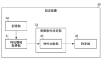
- FIG. 3 is a block diagram showing the functional configuration of the setting device 30 of the first embodiment.
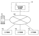
- FIG. 4 is a conceptual diagram showing an example of acquiring characteristic information before and after a part change from another industrial machine connected to the network.
- the setting device 30 includes a characteristic information acquisition unit 31, a control condition determination unit 32, a setting unit 33, a storage unit 34, etc.
- the characteristic information acquisition unit 31 acquires characteristic information before and after a part change (hereinafter also referred to as "characteristic information before and after a part change") in a machine tool 10 in which some parts can be changed by retrofitting.
- the characteristic information acquisition unit 31 acquires characteristic information before and after a part change in the machine tool 10 from the memory unit 34.
- the characteristic information acquisition unit 31 may acquire the information via a network NW, for example, as shown in FIG. 4.
- the network NW may be, for example, a LAN provided in a factory or an Internet line.
- a network NW is connected to multiple machine tools 10a, 10b-10n (hereinafter referred to as "10a-10n") and a server 50.
- the server 50 stores characteristic information before and after part change acquired from the machine tools 10a-10n.
- the machine tools 10a-10n may be machine tools of the same type (same product) or machine tools of different types (different products).
- the characteristic information acquisition unit 31 can acquire characteristic information before and after part change of the machine tool by extracting a machine tool of the same type as the machine tool 10 that is the target of part change from the server 50 via the network NW.
- the characteristic information acquisition unit 31 may acquire characteristic information before and after part change directly from the multiple machine tools 10a-10n via the network NW and store it in the memory unit 34 of the setting device 30 (see FIG. 3).
- control condition determination unit 32 determines the control conditions of the numerical control device 20 after a part change based on characteristic information before and after the part change.
- the control condition determination unit 32 is a functional block that executes a control condition determination method for a machine tool (industrial machine) 10 in which some parts are changeable, by acquiring characteristic information before and after a part change, and determining the control conditions of the numerical control device after a part change based on the characteristic information before and after the part change.
- the control condition determination unit 32 includes a characteristic comparison unit 35 as a functional block for determining the control conditions of the numerical control device 20.
- the characteristic comparison unit 35 compares the characteristic information before the part change with the characteristic information after the part change, and determines the control conditions based on the difference between the two pieces of characteristic information.
- the characteristic comparison unit 35 compares the torque characteristics or motor output characteristics of the motor before and after the part change as the characteristic information before and after the part change.
- the "motor” described in this specification includes the spindle motor 101, X-axis motor 124, Y-axis motor 134, Z-axis motor 115, etc. shown in FIG. 2.
- the setting unit 33 sets at least one of the control conditions determined by the control condition determination unit 32 for the numerical control device 20 that controls the operation of a machine tool having some changeable parts. That is, in the numerical control device 20, the control condition may be set for one motor (e.g., the spindle motor 101), or for multiple other motors.
- the control condition may be set for one motor (e.g., the spindle motor 101), or for multiple other motors.
- the storage unit 34 stores the characteristic information of the motor before the part is changed and the characteristic information after the part is changed.
- the characteristic information after the part is changed for example, the specification data (design data) of the replaced motor can be used.
- the setting device 30 which is made up of the above functional blocks, includes a processor (CPU), ROM, RAM, etc. (none of which are shown).
- the processor of the setting device 30 reads various programs (e.g., a program for executing the process of setting control conditions) from the ROM and executes calculations based on each program while expanding these programs in the RAM. Based on this calculation, the setting device 30 controls its own hardware resources, thereby realizing the operation of each of the above functional blocks. In other words, the functions of the setting device 30 are realized by the cooperation of hardware and software.
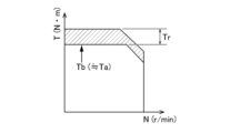
- FIG. 5A is a graph showing the torque characteristics before a part of the machine tool 10 is changed.
- FIG. 5B is a graph showing the torque characteristics after a part of the machine tool 10 is changed.
- FIG. 5C is a graph showing the torque characteristics of the machine tool 10 with the control conditions set after the part is changed.
- the horizontal axis shows the rotation speed N (r/min) and the vertical axis shows the torque T (N ⁇ m).
- the maximum torque value Tb after the part change shown in FIG. 5B exceeds the maximum torque value Ta before the part change.
- the control target is the spindle motor 101
- the maximum torque value after the part change is larger than before the part change, the tool accelerates more than necessary, and the machining result of the work changes.
- the characteristic comparison unit 35 (see FIG. 3) of the setting device 30 compares the torque characteristic before the part change with the torque characteristic after the part change, and determines the control condition based on the difference between the two torque characteristics. Specifically, as shown in FIG.
- the control condition is determined so that the maximum torque value Tb after the part change is lower by the difference Tr of the maximum torque value.
- the setting unit 33 sets the control condition determined by the characteristic comparison unit 35 for the numerical control device 20. As a result, the maximum torque value Tb after the part change can be made to match the maximum torque value Ta before the part change, as shown in FIG. 5C.
- control condition settings can be applied not only to the spindle motor 101, but also to the X-axis motor 124, Y-axis motor 134, Z-axis motor 115, etc.
- the control conditions may also be determined by comparing the output characteristics of the motor before and after the part change.
- the changed motor is basically one that has better overall performance than the motor before the change. However, if some performance is not better, it is sufficient to set control conditions only for the characteristic information that is better than the motor before the change.
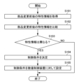
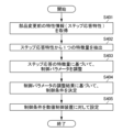
- Figure 6 is a flowchart showing the control condition setting process executed by the setting device 30 of the first embodiment.
- step S101 of FIG. 6 the characteristic information acquisition unit 31 acquires characteristic information before and after the part change of the machine tool 10.
- the characteristic comparison unit 35 control condition determination unit 32 compares the characteristic information before the part change of the machine tool 10 with the characteristic information after the part change.
- step S103 the characteristic comparison unit 35 determines whether the characteristic information before the part change and the characteristic information after the part change are different. If the characteristic comparison unit 35 determines in step S103 that the characteristic information before the part change and the characteristic information after the part change are different, the process proceeds to step S104. On the other hand, if the characteristic comparison unit 35 determines in step S103 that the characteristic information before the part change and the characteristic information after the part change are the same, the process of this flowchart ends.
- step S104 the characteristic comparison unit 35 determines the control conditions based on the difference between the two pieces of characteristic information.
- step S105 the setting unit 33 sets the control conditions determined by the control condition determination unit 32 for the numerical control device 20. After the control conditions are set for the numerical control device 20 in step S105, the processing of this flowchart ends.
- the setting device 30 of the first embodiment described above includes a control condition determination unit 32 that determines the control conditions of the numerical control device 20 after the part change based on the characteristic information before and after the part change, and a setting unit 33 that sets the determined control conditions for the numerical control device 20.
- a control condition determination unit 32 that determines the control conditions of the numerical control device 20 after the part change based on the characteristic information before and after the part change
- a setting unit 33 that sets the determined control conditions for the numerical control device 20. This allows the operating characteristics of the machine tool 10 after the part change to be closer to the operating characteristics before the part change, so that the fluctuation of the operating characteristics of the machine tool 10 after the part change can be suppressed.
- the control conditions are determined so that the operating characteristics of the machine tool 10 after the part change and the operating characteristics before the part change match, so that the fluctuation of the operating characteristics of the machine tool 10 after the part change can be reduced to almost zero.
- control conditions are determined by comparing the torque characteristics (or output characteristics) of the motor before and after the part change, so that the fluctuation of the operating characteristics before and after the part change can be effectively suppressed, for example, when the press is operated at full torque, or when the spindle motor of the machine tool is accelerated and decelerated at full output, etc.
- the machine tool control system 1 of the second embodiment differs from the first embodiment in that the frequency characteristics of the feed shaft including the motor or the frequency characteristics of the spindle including the motor are used as characteristic information before and after part replacement.
- the configuration other than the setting device is substantially the same as that of the first embodiment. Therefore, in the description of the second embodiment, only the configuration of the setting device is illustrated, and the entire machine tool control system 1 is not illustrated.
- members equivalent to those of the first embodiment are given the same reference numerals as those of the first embodiment, and duplicated descriptions are omitted (the same applies to the third and fourth embodiments).
- FIG. 7 is a block diagram showing the functional configuration of the setting device 30A of the second embodiment.
- the setting device 30A of the second embodiment includes a characteristic information acquisition unit 31, a control condition determination unit 32, a setting unit 33, a memory unit 34, a frequency characteristic extraction unit 36, and a frequency characteristic adjustment unit 37.
- the functions and actions of the setting unit 33 and the memory unit 34 are the same as those of the first embodiment.
- the characteristic information acquisition unit 31 acquires, as characteristic information before and after a part change of the machine tool 10, the frequency characteristics of the feed shaft including the motor or the frequency characteristics of the spindle including the motor before the part change, and the frequency characteristics of the feed shaft including the motor or the frequency characteristics of the spindle including the motor after the part change.
- the "frequency characteristics of the feed shaft including the motor” refers to the frequency characteristics in a state where the motor is loaded by the torsional torque of the ball screw when the feed shaft including the motor is, for example, a ball screw (linear axis) driven by a motor.
- the "frequency characteristics of the spindle including the motor” refers to the frequency characteristics when the motor connected to the spindle is rotated without load.
- the "frequency characteristics of the feed shaft including the motor or the frequency characteristics of the spindle including the motor” will also be referred to as the "frequency characteristics of the feed shaft or the spindle including the motor”.
- the frequency characteristic extraction unit 36 extracts at least one of the phase margin, gain margin, gain characteristic of the complementary sensitivity function, control band, and gain characteristic of the sensitivity function as a "frequency-related characteristic" from the frequency characteristic of the feed shaft including the motor before the part change or the frequency characteristic of the spindle including the motor before the part change acquired by the characteristic information acquisition unit 31.
- the item of the frequency-related characteristic to be extracted can be selected/designated, for example, by the operator operating the operation input unit 209 (see FIG. 2).
- Figure 8 is a conceptual diagram of a basic feedback control system.
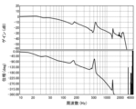
- Figures 9A to 9C are graphs (Bode plots) showing specific examples of frequency-related characteristics.
- Figure 9A is a graph showing open loop characteristics and phase and gain margins.
- Figure 9B is a graph showing the gain characteristics and control band of the complementary sensitivity function.
- Figure 9C is a graph showing the gain characteristics of the sensitivity function.
- the upper side is a gain diagram (horizontal axis: frequency/vertical axis: gain).
- the lower side is a phase diagram (horizontal axis: frequency/vertical axis: phase).
- the controller C is, for example, the spindle control unit 211 (see FIG. 2)
- the controlled object P is the spindle motor 101 and the tool attached to the tip of the spindle motor 101.
- the controller C is, for example, the X-axis motor control unit 213, the controlled object P is a servo motor, coupling, ball screw, table, etc.
- the frequency characteristics of the open loop L1 shown in Figure 8 are shown in the graph in Figure 9A.
- the gain margin shown in the upper part of Figure 9A represents the margin until the gain becomes 1x (0 dB) when the phase of the loop gain shown in the lower part is 180°.
- the phase margin shown in the lower part of Figure 9A represents the margin until the phase of the loop gain becomes 180° when the gain shown in the upper part is 1x (0 dB).
- the frequency characteristics of the closed loop L2 shown in FIG. 8 are shown in the graphs of the complementary sensitivity function and control band shown in FIG. 9B.
- the graph of the complementary sensitivity function shown by the solid line in FIG. 9B represents the transfer function of the closed loop, and is an index showing the degree of the influence of the observation noise and the degree of stability against the uncertainty of the characteristics of the controlled object.
- the upper diagram in FIG. 9B is a graph showing the gain characteristics of the complementary sensitivity function.
- the lower diagram in FIG. 9B is a graph showing the phase characteristics of the complementary sensitivity function.
- the control band is an index showing the speed of response of the control system, and indicates the width of the frequency to which it can respond.
- the control band is generally expressed as the frequency range up to which the gain of the complementary sensitivity function falls to -3 dB.
- the frequency at which the gain of the complementary sensitivity function falls to -3 dB is about 200 Hz.
- the control band (upper limit) is shown by a hollow circle near 200 Hz on the gain diagram. If the control band is high, it can respond to higher frequencies. In other words, a high control band means a faster response.
- the dashed line graphs in Figures 9B and 9C show the gain of the weighting function (frequency-dependent function) for the complementary sensitivity function and the sensitivity function. It is desirable for the complementary sensitivity function and the sensitivity function to have small disturbance suppression (nominal performance) and small stability against changes in the controlled object (robust stability), but since these characteristics are in a trade-off relationship, it is difficult to make both small. Therefore, the weights may be set based on the magnitude of change for each controlled object and the required response performance. In this embodiment, the weights can be determined by providing a certain margin from the characteristics before the part change.
- the weights may be set to the gain characteristics of the complementary sensitivity function and the sensitivity function before the part change + 10 dB.
- the parameter values of the controller that become the complementary sensitivity function and the sensitivity function are calculated so that they are equal to or less than the gain of the weighting function, and the control parameters are adjusted.
- the frequency characteristics of loop L3 shown in Figure 8 are shown as the graph of the sensitivity function in Figure 9C.
- the sensitivity function is an index that indicates disturbance suppression ability.
- the upper diagram in Figure 9C is a graph showing the gain characteristics of the sensitivity function.
- the lower diagram in Figure 9C is a graph showing the phase characteristics of the sensitivity function.
- the dashed line graph in Figure 9C indicates the gain of the weighting function with respect to the sensitivity function.
- the weighting is determined from the characteristics before the part is changed, and after the part is changed, the control parameters are adjusted so that they are equal to or less than the gain of this weighting function.
- the frequency characteristic adjustment unit 37 adjusts the control parameters of the feed axis including the motor after the part change or the control parameters of the spindle including the motor after the part change based on the frequency-related characteristics extracted by the frequency characteristic extraction unit 36.
- the control parameters can be adjusted, for example, so that the gains of the complementary sensitivity function and the sensitivity function are equal to or less than the set weight for the complementary sensitivity function and the sensitivity function.
- the control band can be adjusted so that the control band is higher than before the part change.
- control parameters of the feed axis including the motor or the spindle including the motor are also referred to as the "control parameters of the feed axis or the spindle including the motor”.
- the control condition determination unit 32 determines the control conditions of the numerical control device 20 after the parts are changed, based on the control parameters adjusted by the frequency characteristic adjustment unit 37. Specifically, the control condition determination unit 32 converts the control parameters adjusted by the frequency characteristic adjustment unit 37 into a format that can be applied or set to the numerical control device 20. For example, if the control parameters derived by the frequency characteristic adjustment unit 37 are control parameters of a controller order that is not practical for application to the numerical control device 20, the control condition determination unit 32 reduces the controller order to make it an applicable control parameter. In addition, the control condition determination unit 32 performs unit conversion, for example, if the units do not match those of the control parameters to be applied to the numerical control device 20.
- Fig. 10 is a flow chart showing the control condition setting process executed by the setting device 30A.
- characteristic information acquisition unit 31 acquires the frequency characteristics of a feed axis including a motor or the frequency characteristics of a spindle including a motor as characteristic information before and after a part change of machine tool 10.
- the frequency characteristic extraction unit 36 extracts at least one frequency-related characteristic, including the phase margin, the gain margin, the gain characteristic of the complementary sensitivity function, the control band, and the gain characteristic of the sensitivity function, from the frequency characteristic of the feed axis including the motor before the part change or the frequency characteristic of the spindle including the motor before the part change.
- step S203 the frequency characteristic adjustment unit 37 adjusts the control parameters of the feed axis including the motor after the part change or the control parameters of the spindle including the motor after the part change based on the frequency-related characteristics extracted by the frequency characteristic extraction unit 36.
- step S204 the control condition determination unit 32 determines the control conditions of the numerical control device 20 after the part change based on the control parameters adjusted by the frequency characteristic adjustment unit 37.
- step S205 the setting unit 33 sets the control conditions determined by the control condition determination unit 32 for the numerical control device 20. After the control conditions are set for the numerical control device 20 in step S205, the processing of this flowchart ends.
- the setting device 30A of the second embodiment described above includes a frequency characteristic extraction unit 36 that extracts at least one frequency-related characteristic from the frequency characteristics of the feed shaft including the motor before and after the part change or the frequency characteristics of the spindle including the motor before the part change, a frequency characteristic adjustment unit 37 that adjusts the control parameters of the feed shaft including the motor after the part change or the control parameters of the spindle including the motor after the part change based on the extracted frequency-related characteristic, a control condition determination unit 32 that determines the control conditions of the numerical control device 20 after the part change based on the adjusted control parameters, and a setting unit 33 that sets the determined control conditions for the numerical control device 20.
- a frequency characteristic extraction unit 36 that extracts at least one frequency-related characteristic from the frequency characteristics of the feed shaft including the motor before and after the part change or the frequency characteristics of the spindle including the motor before the part change
- a frequency characteristic adjustment unit 37 that adjusts the control parameters of the feed shaft including the motor after the part change or the control parameters of the spindle including the motor after
- the operating characteristics of the machine tool 10 after the part change whose operation is controlled by the numerical control device 20, can be made to approach the operating characteristics before the part change, so that fluctuations in the operating characteristics of the machine tool 10 after the part change can be suppressed.
- the machine tool control system 1 of the third embodiment differs from the first embodiment in that a model matching technique is used to make the frequency characteristics of the feed axis or spindle including the motor after part replacement closer to the frequency characteristics of the feed axis or spindle including the motor before part replacement.
- FIG. 11 is a block diagram showing the functional configuration of the setting device 30B of the third embodiment.
- the setting device 30B includes a characteristic information acquisition unit 31, a control condition determination unit 32, a setting unit 33, a memory unit 34, a frequency characteristic adjustment unit 37, and a frequency characteristic model creation unit 38.
- the functions and operations of the characteristic information acquisition unit 31 and the control condition determination unit 32 are the same as those in the second embodiment.
- the functions and operations of the setting unit 33 and the memory unit 34 are the same as those in the first embodiment.
- the frequency characteristic model creation unit 38 creates a frequency characteristic model of the feed shaft including the motor before the part change or the frequency characteristic model of the spindle including the motor before the part change based on the frequency characteristic of the feed shaft including the motor before the part change or the frequency characteristic model of the spindle including the motor before the part change.
- the format of the frequency characteristic model is not particularly limited and may be created in any format.
- the frequency characteristic model may be created as a mathematical expression of a transfer function or as a data string of complex numbers of the frequency characteristics.
- the frequency characteristic adjustment unit 37 adjusts the control parameters of the feed shaft including the motor after the part change or the control parameters of the spindle including the motor after the part change by model matching the frequency characteristic model created by the frequency characteristic model creation unit 38 with the frequency characteristics of the feed shaft including the motor after the part change or the frequency characteristics of the spindle including the motor after the part change.
- FIG. 12A is a graph showing an example of the frequency characteristic of the complementary sensitivity function before the part change.
- FIG. 12B is a graph showing an example of the frequency characteristic of the complementary sensitivity function after the part change.
- the upper side is a gain diagram (horizontal axis: frequency/vertical axis: gain).
- the lower side is a phase diagram (horizontal axis: frequency/vertical axis: phase).
- the frequency characteristic model creation unit 38 creates a formula or a data string representing the frequency characteristic shown in FIG. 12A as a frequency characteristic model as a desired characteristic (normative characteristic) to be approximated after the part change.
- the frequency characteristic adjustment unit 37 adjusts the control parameters to perform model matching so that the frequency characteristic after the part change shown in FIG. 12B approaches the frequency characteristic before the part change shown in FIG. 12A.
- the control condition determination unit 32 sets the control conditions of the numerical control device 20 after the part change based on the control parameters adjusted by the frequency characteristic adjustment unit 37.
- the method of model matching in the frequency characteristic adjustment unit 37 is not particularly limited, and any method may be used. For example, a method such as optimization may be used.
- the frequency characteristics before and after the part change that are acquired may be frequency characteristics of open loop characteristics.
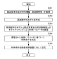
- FIG. 13 is a flowchart showing the control condition setting process executed by the setting device 30B of the third embodiment.
- step S301 of FIG. 13 the characteristic information acquisition unit 31 acquires the frequency characteristics of the feed axis including the motor or the frequency characteristics of the spindle including the motor as characteristic information before and after the part change of the machine tool 10.
- step S302 the frequency characteristic model creation unit 38 creates a frequency characteristic model of the feed shaft or spindle including the motor before and after the part change based on the frequency characteristics of the feed shaft or spindle including the motor before and after the part change acquired by the characteristic information acquisition unit 31.
- step S303 the frequency characteristic adjustment unit 37 adjusts the control parameters of the feed shaft including the motor after the part change or the control parameters of the spindle including the motor after the part change by model matching between the frequency characteristic model created by the frequency characteristic model creation unit 38 and the frequency characteristics of the feed shaft or spindle including the motor after the part change.
- step S304 the control condition determination unit 32 determines the control conditions of the numerical control device 20 after the part change based on the control parameters adjusted by the frequency characteristic adjustment unit 37.
- step S305 the setting unit 33 sets the control conditions determined by the control condition determination unit 32 for the numerical control device 20. After the control conditions are set for the numerical control device 20 in step S305, the processing of this flowchart ends.
- the setting device 30B of the third embodiment described above includes a frequency characteristic model creation unit 38 that creates a frequency characteristic model of the feed axis or spindle including the motor before the part change based on the frequency characteristics of the feed axis or spindle including the motor before the change, a frequency characteristic adjustment unit 37 that adjusts the control parameters of the feed axis or spindle including the motor after the part change by model matching between the created frequency characteristic model and the frequency characteristics of the feed axis or spindle including the motor after the part change, a control condition determination unit 32 that determines the control conditions of the numerical control device 20 after the part change based on the adjusted control parameters, and a setting unit 33 that sets the determined control conditions for the numerical control device 20.
- a frequency characteristic model creation unit 38 that creates a frequency characteristic model of the feed axis or spindle including the motor before the part change based on the frequency characteristics of the feed axis or spindle including the motor before the change
- a frequency characteristic adjustment unit 37 that adjusts the control parameters of the feed
- the operating characteristics before and after the part change do not have to match across the entire range. For example, in areas where the gain characteristics of the frequency characteristics are low, the motor output is small, so even if the difference between the characteristics before and after the change is large, no practical problems will occur.
- the machine tool control system 1 of the fourth embodiment differs from the first embodiment in that the step response characteristic of a feed axis including a motor or the step response characteristic of a spindle including a motor is used as characteristic information before part replacement.
- FIG. 14 is a block diagram showing the functional configuration of the setting device 30C of the fourth embodiment.
- the setting device 30C of the fourth embodiment includes a characteristic information acquisition unit 31, a control condition determination unit 32, a setting unit 33, a memory unit 34, a step response characteristic extraction unit 39, and a step response characteristic adjustment unit 40.
- the functions and actions of the setting unit 33 and the memory unit 34 are the same as those of the first embodiment.
- the characteristic information acquisition unit 31 acquires the step response characteristic of the feed axis including the motor or the step response characteristic of the spindle including the motor before the part change as characteristic information before the part change of the machine tool 10.
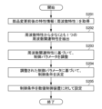
- the "step response characteristic of the feed axis including the motor or the step response characteristic of the spindle including the motor” is also referred to as the “step response characteristic of the feed axis or spindle including the motor”.
- the step response characteristic extraction unit 39 extracts at least one characteristic quantity, namely, rise time, settling time, and maximum overshoot amount, from the step response characteristic of the feed axis including the motor before the part change acquired by the characteristic information acquisition unit 31 or the step response characteristic of the spindle including the motor before the part change.
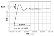
- FIG. 15 is a graph showing an example of the step response characteristic of the motor speed.
- the horizontal axis indicates time (msec) and the vertical axis indicates amplitude (mm/min).
- the step response characteristic of the motor has the characteristic quantities of rise time, settling time, and maximum overshoot amount.
- the rise time is the time required for the amplitude to change from 10% to 90% of the final value.
- the settling time is the time required for the amplitude to fall within a range of 5% of the final value.
- the maximum overshoot amount is the difference between the maximum value and the final value.
- the step response characteristic extraction unit 39 extracts at least one characteristic quantity of the rise time, settling time, and maximum overshoot amount from the step response characteristic shown in FIG. 15.
- the step response characteristic adjustment unit 40 adjusts the control parameters of the feed axis including the motor or the control parameters of the spindle including the motor after the part change based on the step response characteristic extracted by the step response characteristic extraction unit 39 .
- the control condition determination unit 32 determines the control conditions of the numerical control device 20 after the parts are changed, based on the adjustment results of the control parameters adjusted by the step response characteristic adjustment unit 40 .
- Figure 16 is a flowchart showing the control condition setting process executed by the setting device 30C of the fourth embodiment.
- step S401 of FIG. 16 the characteristic information acquisition unit 31 acquires the step response characteristic of the feed axis including the motor or the step response characteristic of the spindle including the motor before the part change as characteristic information before and after the part change of the machine tool 10.
- step S402 the step response characteristic extraction unit 39 extracts at least one characteristic quantity, namely, rise time, settling time, and maximum overshoot amount, from the step response characteristic of the feed axis including the motor before the part change acquired by the characteristic information acquisition unit 31 or the step response characteristic of the spindle including the motor before the part change.
- step S403 the step response characteristic adjustment unit 40 adjusts the control parameters of the feed axis including the motor or the control parameters of the spindle including the motor after the part change based on the feature amount of the step response characteristic extracted by the step response characteristic extraction unit 39.
- step S404 the control condition determination unit 32 determines the control conditions of the numerical control device 20 after the part change based on the results of the control parameters adjusted by the frequency characteristic adjustment unit 37.
- step S405 the setting unit 33 sets the control conditions determined by the control condition determination unit 32 for the numerical control device 20. After the control conditions are set for the numerical control device 20 in step S405, the processing of this flowchart ends.
- the setting device 30C of the fourth embodiment described above includes a characteristic information acquisition unit 31 that acquires the step response characteristic of the feed axis including the motor before the part change or the step response characteristic of the spindle including the motor before the part change as characteristic information before the part change of the machine tool 10, a step response characteristic extraction unit 39 that extracts at least one feature value of the rise time, the settling time, and the maximum overshoot amount from the step response characteristic of the feed axis including the motor before the part change or the step response characteristic of the spindle including the motor before the part change, a step response characteristic adjustment unit 40 that adjusts the control parameter of the feed axis including the motor after the part change or the control parameter of the spindle including the motor after the part change based on the step response characteristic, and a control condition determination unit 32 that determines the control condition of the numerical control device 20 after the part change based on the adjustment result of the control parameter.
- a characteristic information acquisition unit 31 that acquires the step response characteristic of the feed axis including the motor before the part change or
- the operating characteristic of the machine tool 10 after the part change whose operation is controlled by the numerical control device 20
- the difference in time response including nonlinear elements (friction, etc.) that cannot be expressed by frequency characteristics can be evaluated, so that the operation of the controlled object can be more reliably evaluated.
- the control parameters of the feed axis including the motor after the part change or the control parameters of the spindle including the motor may be adjusted based on the time series data of the step response characteristics.
- the characteristic information acquisition unit 31 acquires time series data of the step response characteristics of the feed axis including the motor or the spindle before and after the part change.
- the step response characteristic adjustment unit 40 adjusts the control parameters of the feed axis including the motor after the part change or the control parameters of the spindle including the motor so that the difference between the time series data of the step response characteristics of the feed axis including the motor or the spindle before and after the part change acquired by the characteristic information acquisition unit 31 is minimized.
- the operating characteristics of the machine tool 10 after the part change can be made closer to the operating characteristics before the part change, thereby suppressing fluctuations in the operating characteristics of the machine tool 10 after the part change.
- the control condition determination unit 32 of each of the above-described embodiments executes a control condition determination method for a machine tool (industrial machine) 10 in which some parts are changeable, by acquiring characteristic information before and after a part is changed, and determining the control conditions of the numerical control device after the part is changed based on the characteristic information before and after the part is changed.
- this control condition determination method the operating characteristics of the machine tool 10 after a part is changed can be made closer to the operating characteristics before the part is changed, thereby suppressing fluctuations in the operating characteristics of the machine tool 10 after the part is changed.
- the control conditions determined by the setting device are set in the numerical control device, thereby providing the effect of suppressing changes in the operating characteristics of the machine tool after the part is changed.
- the setting device may be connected to the numerical control device, or may be provided inside the numerical control device, or may be provided in an external computer system connected via a network.
- the setting device may have all of its hardware resources located in the same housing, or may be distributed across multiple housings.
- One setting device may be connected to multiple numerical control devices, or multiple setting devices may be connected to one or multiple numerical control devices.
- a cutting machine has been described as an example of a machine tool, but the present invention is not limited to this.
- the machine tool may be, for example, an injection molding machine, an electric discharge machine, etc.
- the industrial machine is not limited to a machine tool, and may be, for example, an industrial robot.
- the setting device (30) is a setting device that sets control conditions of a numerical control device (20) that controls the operation of an industrial machine (10) having at least one electric motor, and includes a characteristic information acquisition unit (31) that acquires characteristic information before a part is changed and characteristic information after the part is changed in the industrial machine (10) having some of its parts that are changeable, a control condition determination unit (32) that determines control conditions of the numerical control device after the part is changed based on the characteristic information before the part is changed and the characteristic information after the part is changed, and a setting unit (33) that sets at least one control condition determined by the control condition determination unit (32) for the numerical control device (20) that controls the operation of the industrial machine (10) having some of its parts that are changeable.
- a characteristic information acquisition unit (31) that acquires characteristic information before a part is changed and characteristic information after the part is changed in the industrial machine (10) having some of its parts that are changeable
- a control condition determination unit (32) that determines control conditions of the numerical control device after the part is changed based on the characteristic information before
- the control condition determination section (32) includes a characteristic comparison section (35) which compares characteristic information before the part change with characteristic information after the part change and determines control conditions based on a difference between the two pieces of characteristic information.
- the characteristic comparison section (35) compares the torque characteristics or output characteristics of the electric motor before and after the part change.
- the characteristic information before the part change is the frequency characteristic of a linear axis or a rotary axis including the electric motor before the part change
- a frequency characteristic adjustment unit (37) is provided that adjusts control parameters of the linear axis or the rotary axis including the electric motor after the part change based on the frequency characteristic
- the control condition determination unit (32) determines the control conditions of the numerical control device (20) after the part change based on the control parameters adjusted by the frequency characteristic adjustment unit (37).
- the system further includes a frequency characteristic extraction unit (36) that extracts at least one frequency-related characteristic, selected from the frequency characteristics of the linear axis or rotating axis including the electric motor before the part change, of a phase margin, a gain margin, a gain characteristic of a complementary sensitivity function, a control band, and a gain characteristic of a sensitivity function, and the frequency characteristic adjustment unit (37) adjusts a control parameter of the linear axis or rotating axis including the electric motor after the part change, based on the frequency-related characteristic extracted by the frequency characteristic extraction unit (36).
- the system further includes a frequency characteristic model creation unit (38) that creates a frequency characteristic model of the linear axis or rotation axis including the electric motor before the part change based on the frequency characteristic of the linear axis or rotation axis including the electric motor before the part change, and the frequency characteristic adjustment unit (37) adjusts a control parameter of the linear axis or rotation axis including the electric motor after the part change by model matching between the frequency characteristic model and the frequency characteristic of the linear axis or rotation axis including the electric motor after the part change.
- the characteristic information before the part change is a step response characteristic of a linear axis or a rotary axis including the electric motor before the part change
- a step response characteristic adjustment unit (40) is provided that adjusts a control parameter of the linear axis or the rotary axis including the electric motor after the part change based on the step response characteristic
- the control condition determination unit (32) determines the control condition of the numerical control device (20) after the part change based on the adjustment result of the control parameter by the step response characteristic adjustment unit (40).
- the system includes a step response characteristic extraction unit (39) that extracts at least one feature value of rise time, settling time, and maximum overshoot amount from the step response characteristics of the linear axis or rotary axis including the electric motor before the part change, and the step response characteristic adjustment unit (40) adjusts a control parameter of the linear axis or rotary axis including the electric motor after the part change based on the feature value extracted by the step response characteristic extraction unit (39).
- the step response characteristic adjustment unit (40) adjusts a control parameter of the linear axis or rotary axis including the electric motor after the part change so that a difference between a step response characteristic of the linear axis or rotary axis including the electric motor before the part change and a step response characteristic of the linear axis or rotary axis including the electric motor after the part change is minimized.
- a method for determining control conditions for a numerical control device that controls the operation of an industrial machine having at least one electric motor comprising the steps of: obtaining characteristic information before a part is changed and characteristic information after the part is changed for the industrial machine, and determining control conditions for the numerical control device after the part is changed based on the characteristic information before the part is changed and the characteristic information after the part is changed.
- Machine tool control system 10: Machine tool
- 20 Numerical control device, 30, 30A-30C: Setting device
- 31 Characteristics information acquisition unit
- 32 Control condition determination unit
- 33 Setting unit
- 34 Memory unit
- 35 Characteristics comparison unit
- 36 Frequency characteristics extraction unit
- 37 Frequency characteristics adjustment unit
- 38 Frequency characteristics model creation unit
- 39 Step response characteristics extraction unit
- 40 Step response characteristics adjustment unit
- 101 Spindle motor
- 111 Spindle
- 114 123
- 133 Feed axis
- 115 Z-axis motor
- 124 X-axis motor
- 134 Y-axis motor
Landscapes
- Engineering & Computer Science (AREA)
- Human Computer Interaction (AREA)
- Manufacturing & Machinery (AREA)
- Physics & Mathematics (AREA)
- General Physics & Mathematics (AREA)
- Automation & Control Theory (AREA)
- Numerical Control (AREA)
Priority Applications (2)
| Application Number | Priority Date | Filing Date | Title |
|---|---|---|---|
| JP2024560980A JPWO2024116232A1 (https=) | 2022-11-28 | 2022-11-28 | |
| PCT/JP2022/043736 WO2024116232A1 (ja) | 2022-11-28 | 2022-11-28 | 設定装置及び制御条件の決定方法 |
Applications Claiming Priority (1)
| Application Number | Priority Date | Filing Date | Title |
|---|---|---|---|
| PCT/JP2022/043736 WO2024116232A1 (ja) | 2022-11-28 | 2022-11-28 | 設定装置及び制御条件の決定方法 |
Publications (1)
| Publication Number | Publication Date |
|---|---|
| WO2024116232A1 true WO2024116232A1 (ja) | 2024-06-06 |
Family
ID=91323240
Family Applications (1)
| Application Number | Title | Priority Date | Filing Date |
|---|---|---|---|
| PCT/JP2022/043736 Ceased WO2024116232A1 (ja) | 2022-11-28 | 2022-11-28 | 設定装置及び制御条件の決定方法 |
Country Status (2)
| Country | Link |
|---|---|
| JP (1) | JPWO2024116232A1 (https=) |
| WO (1) | WO2024116232A1 (https=) |
Citations (7)
| Publication number | Priority date | Publication date | Assignee | Title |
|---|---|---|---|---|
| JPS6311289A (ja) * | 1986-07-01 | 1988-01-18 | 株式会社日立製作所 | ロボツトの基準姿勢デ−タ読込方式 |
| JPH02145274A (ja) * | 1988-11-29 | 1990-06-04 | Toshiba Corp | ロボットの制御装置 |
| JPH06131032A (ja) * | 1992-04-14 | 1994-05-13 | Hitachi Ltd | ロボット装置およびロボット装置のティ−チング方法。 |
| JP2006123157A (ja) * | 2004-09-28 | 2006-05-18 | Nidec Sankyo Corp | ロボットを教示するロボット教示用プログラム、及びこれに使用するカセット、位置測定器具並びにこれらを利用したロボット作動方法 |
| JP2012040637A (ja) * | 2010-08-18 | 2012-03-01 | Iai:Kk | 制御装置、産業用ロボット、座標系の再現方法、及びプログラム |
| JP2017058480A (ja) * | 2015-09-15 | 2017-03-23 | 富士ゼロックス株式会社 | 搬送装置、定着装置、及び画像形成装置 |
| WO2021157676A1 (ja) * | 2020-02-07 | 2021-08-12 | ファナック株式会社 | 診断装置 |
-
2022
- 2022-11-28 JP JP2024560980A patent/JPWO2024116232A1/ja active Pending
- 2022-11-28 WO PCT/JP2022/043736 patent/WO2024116232A1/ja not_active Ceased
Patent Citations (7)
| Publication number | Priority date | Publication date | Assignee | Title |
|---|---|---|---|---|
| JPS6311289A (ja) * | 1986-07-01 | 1988-01-18 | 株式会社日立製作所 | ロボツトの基準姿勢デ−タ読込方式 |
| JPH02145274A (ja) * | 1988-11-29 | 1990-06-04 | Toshiba Corp | ロボットの制御装置 |
| JPH06131032A (ja) * | 1992-04-14 | 1994-05-13 | Hitachi Ltd | ロボット装置およびロボット装置のティ−チング方法。 |
| JP2006123157A (ja) * | 2004-09-28 | 2006-05-18 | Nidec Sankyo Corp | ロボットを教示するロボット教示用プログラム、及びこれに使用するカセット、位置測定器具並びにこれらを利用したロボット作動方法 |
| JP2012040637A (ja) * | 2010-08-18 | 2012-03-01 | Iai:Kk | 制御装置、産業用ロボット、座標系の再現方法、及びプログラム |
| JP2017058480A (ja) * | 2015-09-15 | 2017-03-23 | 富士ゼロックス株式会社 | 搬送装置、定着装置、及び画像形成装置 |
| WO2021157676A1 (ja) * | 2020-02-07 | 2021-08-12 | ファナック株式会社 | 診断装置 |
Also Published As
| Publication number | Publication date |
|---|---|
| JPWO2024116232A1 (https=) | 2024-06-06 |
Similar Documents
| Publication | Publication Date | Title |
|---|---|---|
| US7595602B2 (en) | Apparatus for machine tool feedrate override using limiting parameters corresponding to actual spindle speed | |
| EP2634657B1 (en) | Numerical control method | |
| JP4813912B2 (ja) | 未加工品と工作機械の工具との間の相対運動の運動分割方法、および運動分割を実施するための工作機械 | |
| EP1667001B1 (en) | Controller | |
| JP6802213B2 (ja) | 工具選定装置及び機械学習装置 | |
| US6316903B1 (en) | Synchronous controller | |
| JP3545006B2 (ja) | 2自由度制御装置及び電動機のサーボ制御装置 | |
| JPWO2012057219A1 (ja) | 工作機械の数値制御方法及び数値制御装置 | |
| CN110941242B (zh) | 电动机控制装置 | |
| JP3558508B2 (ja) | Nc工作機械の制御装置 | |
| WO2024232063A9 (ja) | 制御装置及びコンピュータ読み取り可能な記録媒体 | |
| US11003161B2 (en) | Numerical controller | |
| US11340587B2 (en) | Numerical controller | |
| US11402824B2 (en) | Numerical controller | |
| WO2024116232A1 (ja) | 設定装置及び制御条件の決定方法 | |
| JP5494378B2 (ja) | ねじ切り制御方法及びその装置 | |
| JP5897259B2 (ja) | 工作機械およびその制御方法 | |
| JP7788921B2 (ja) | 負荷装置の位置による特性変動を考慮したパラメータ調整装置および方法 | |
| JP7410272B2 (ja) | 速度調整支援装置 | |
| CN109884982B (zh) | 数值控制装置 | |
| JP2008225632A (ja) | Nc制御のサーボ駆動装置 | |
| CN120344929B (zh) | 消耗电量调整装置、数控装置及消耗电量调整方法 | |
| WO2026013802A1 (ja) | 制御装置 | |
| JP7744554B1 (ja) | 制御装置、及びコンピュータ読み取り可能な記録媒体 | |
| JP7502135B2 (ja) | ロボットプログラム調整装置 |
Legal Events
| Date | Code | Title | Description |
|---|---|---|---|
| 121 | Ep: the epo has been informed by wipo that ep was designated in this application |
Ref document number: 22967069 Country of ref document: EP Kind code of ref document: A1 |
|
| WWE | Wipo information: entry into national phase |
Ref document number: 2024560980 Country of ref document: JP |
|
| NENP | Non-entry into the national phase |
Ref country code: DE |
|
| 122 | Ep: pct application non-entry in european phase |
Ref document number: 22967069 Country of ref document: EP Kind code of ref document: A1 |