WO2024105913A1 - 車両用補強部材および車両 - Google Patents
車両用補強部材および車両 Download PDFInfo
- Publication number
- WO2024105913A1 WO2024105913A1 PCT/JP2023/021775 JP2023021775W WO2024105913A1 WO 2024105913 A1 WO2024105913 A1 WO 2024105913A1 JP 2023021775 W JP2023021775 W JP 2023021775W WO 2024105913 A1 WO2024105913 A1 WO 2024105913A1
- Authority
- WO
- WIPO (PCT)
- Prior art keywords
- passage
- oil chamber
- oil
- piston
- vehicle
- Prior art date
- Legal status (The legal status is an assumption and is not a legal conclusion. Google has not performed a legal analysis and makes no representation as to the accuracy of the status listed.)
- Ceased
Links
Images


Classifications
-
- B—PERFORMING OPERATIONS; TRANSPORTING
- B62—LAND VEHICLES FOR TRAVELLING OTHERWISE THAN ON RAILS
- B62K—CYCLES; CYCLE FRAMES; CYCLE STEERING DEVICES; RIDER-OPERATED TERMINAL CONTROLS SPECIALLY ADAPTED FOR CYCLES; CYCLE AXLE SUSPENSIONS; CYCLE SIDECARS, FORECARS, OR THE LIKE
- B62K21/00—Steering devices
- B62K21/08—Steering dampers
-
- F—MECHANICAL ENGINEERING; LIGHTING; HEATING; WEAPONS; BLASTING
- F16—ENGINEERING ELEMENTS AND UNITS; GENERAL MEASURES FOR PRODUCING AND MAINTAINING EFFECTIVE FUNCTIONING OF MACHINES OR INSTALLATIONS; THERMAL INSULATION IN GENERAL
- F16F—SPRINGS; SHOCK-ABSORBERS; MEANS FOR DAMPING VIBRATION
- F16F9/00—Springs, vibration-dampers, shock-absorbers, or similarly-constructed movement-dampers using a fluid or the equivalent as damping medium
- F16F9/06—Springs, vibration-dampers, shock-absorbers, or similarly-constructed movement-dampers using a fluid or the equivalent as damping medium using both gas and liquid
-
- F—MECHANICAL ENGINEERING; LIGHTING; HEATING; WEAPONS; BLASTING
- F16—ENGINEERING ELEMENTS AND UNITS; GENERAL MEASURES FOR PRODUCING AND MAINTAINING EFFECTIVE FUNCTIONING OF MACHINES OR INSTALLATIONS; THERMAL INSULATION IN GENERAL
- F16F—SPRINGS; SHOCK-ABSORBERS; MEANS FOR DAMPING VIBRATION
- F16F9/00—Springs, vibration-dampers, shock-absorbers, or similarly-constructed movement-dampers using a fluid or the equivalent as damping medium
- F16F9/32—Details
- F16F9/34—Special valve constructions; Shape or construction of throttling passages
- F16F9/342—Throttling passages operating with metering pins
-
- F—MECHANICAL ENGINEERING; LIGHTING; HEATING; WEAPONS; BLASTING
- F16—ENGINEERING ELEMENTS AND UNITS; GENERAL MEASURES FOR PRODUCING AND MAINTAINING EFFECTIVE FUNCTIONING OF MACHINES OR INSTALLATIONS; THERMAL INSULATION IN GENERAL
- F16F—SPRINGS; SHOCK-ABSORBERS; MEANS FOR DAMPING VIBRATION
- F16F9/00—Springs, vibration-dampers, shock-absorbers, or similarly-constructed movement-dampers using a fluid or the equivalent as damping medium
- F16F9/32—Details
- F16F9/34—Special valve constructions; Shape or construction of throttling passages
- F16F9/346—Throttling passages in the form of slots arranged in cylinder walls
Definitions
- This invention relates to a vehicle reinforcement member and a vehicle, and more specifically to a vehicle reinforcement member that is attached between two points on the body of a vehicle and a vehicle equipped with the same.
- dampers that are attached between two points on the vehicle body and utilize viscous damping force have been proposed to improve the vehicle's handling stability and ride comfort. Furthermore, with such dampers, there is a demand for the damping force to be able to be changed according to the passenger's preference, rather than having the damping force be fixed.
- Patent Document 1 discloses a steering damper.
- This steering damper comprises a cylinder body, a rod body connected to the cylinder body so as to be able to appear and disappear, a piston body connected to the rod body and slidably housed within the cylinder body and having a damping means, one chamber and the other chamber defined within the cylinder body by the piston body, a bypass path that allows communication between the one chamber and the other chamber by bypassing the damping means of the piston body, and a control means provided in the bypass path for adjusting the flow rate of hydraulic oil passing through the bypass path.
- the damping force provided by the damping means can be set by adjusting the flow rate of hydraulic oil passing through the bypass path.
- the damper disclosed in Patent Document 1 is a steering damper that is attached between the head pipe on the body frame side of the motorcycle and the fork bracket on the handlebar side, and is intended to improve the feeling when the handlebars of the motorcycle are in a neutral state where they are not steered relative to the body frame.
- the piston body closes the bypass path when the handlebars are in a neutral state, making the damping force in the neutral state greater than the damping force in states other than neutral. This makes it possible to prevent the handlebars from reacting to small vibrations such as shimmying of the front wheel of a traveling motorcycle, improving the steering feeling of the handlebars.
- Patent Document 1 does not disclose any configuration in which the bypass path must be closed by the piston body when the handle is in a neutral position, and the bypass path is always open to allow hydraulic oil to flow regardless of the position of the handle or the piston body. Furthermore, Patent Document 1 does not disclose any mention of suppressing minute deformations and vibrations that occur in the vehicle body other than the handle when the vehicle is traveling.
- the main objective of this invention is therefore to provide a vehicle reinforcement member and a vehicle equipped with the same that suppresses minute deformations and vibrations that occur in the vehicle body while the vehicle is in motion and allows the damping force settings to be changed according to the preferences of the passengers.
- a vehicle reinforcement member comprising: a cylinder; a free piston housed in the cylinder so as to divide the interior of the cylinder into a gas chamber in which gas is sealed and an oil chamber filled with hydraulic oil; a piston housed in the cylinder so as to divide the oil chamber into a first oil chamber and a second oil chamber sandwiched between the gas chamber and the first oil chamber and slidable in the axial direction of the cylinder; a piston rod attached to the piston and extending through the first oil chamber to the outside of the cylinder; a damping force generating section provided on the piston for generating a damping force by causing hydraulic oil to flow between the first oil chamber and the second oil chamber; and a damping force adjusting section for adjusting the damping force, the damping force adjusting section including a housing section provided in the cylinder; a bypass oil passage provided in the housing section and communicating between the first oil chamber and the second oil chamber outside the sliding range of the piston; and an adjusting valve for changing the flow
- the damping force is generated by flowing hydraulic oil between the first oil chamber and the second oil chamber through a damping force generating section provided on the piston in the cylinder. Furthermore, the first oil chamber and the second oil chamber are connected by a bypass oil passage provided in the housing of the damping force adjusting section. The flow area of the bypass oil passage is changed by the adjusting valve, and the flow rate of the hydraulic oil in the bypass oil passage is adjusted, thereby increasing or decreasing the damping force. This allows the damping force setting to be changed according to the rider's preference.
- the damping force set by the damping force adjustment unit can constantly suppress minute deformations and vibrations that occur in the vehicle body. For example, when the vehicle reinforcement member according to the present invention is installed on a two-wheeled vehicle, straight-line stability can be improved, and the degree of straight-line stability can be set according to the rider's preferences by the damping force adjustment unit.
- the bypass oil passage includes a first passage connected to the first oil chamber, a second passage connected to the second oil chamber, and a third passage connecting the first passage and the second passage, the first passage and the second passage intersect with the oil chamber at right angles to the axial direction, the third passage is parallel to the axial direction, and the adjustment valve is provided in the housing portion to change the flow path area between the first passage and the third passage or between the second passage and the third passage.
- the first passage and the second passage are formed to extend in a direction perpendicular to the axial direction of the cylinder, and the third passage is formed to extend parallel to the axial direction, so that the third passage can be easily formed from the first passage.
- the bypass oil passage includes a first passage connected to the first oil chamber and a second passage connected to the second oil chamber, the first passage intersects with the first oil chamber at an obtuse angle with respect to the axial direction, and the second passage intersects with the second oil chamber at an acute angle with respect to the axial direction and communicates with the first passage, and the adjustment valve includes a rotary valve provided in the housing section to change the flow path area between the first and second passages.
- the oil passage length of the bypass oil passage can be shortened and the housing section provided in the cylinder can be made smaller. Also, the flow path area between the first and second passages can be easily adjusted by rotating the rotary valve.
- the housing portion has an opening
- the bypass oil passage includes a first passage connected to the first oil chamber and a second passage connected to the second oil chamber, the first passage communicating the opening with the first oil chamber, and the second passage communicating the opening with the second oil chamber
- the adjustment valve is provided in the housing portion to close the opening and change the flow path area between the first passage and the second passage.
- both the first passage and the second passage can be easily machined from one opening in the housing portion. Also, because the opening in the housing portion is closed by the adjustment valve, no separate plug is required, and the number of parts can be reduced.
- both the first path and the second path intersect with the oil chamber at an obtuse angle with respect to the axial direction, or both the first path and the second path intersect with the oil chamber at an acute angle with respect to the axial direction.
- both the first path and the second path are formed to intersect with the axial direction of the cylinder at an obtuse angle or an acute angle, the housing portion provided in the cylinder can be made smaller.
- a vehicle is also provided that includes a vehicle body and the above-mentioned vehicle reinforcement member that is attached between two points on the vehicle body.
- the vehicle reinforcement member according to the present invention can be suitably used in vehicles such as two-wheeled vehicles and four-wheeled vehicles.
- angles of the first and second paths with respect to the axial direction correspond to the angles with respect to the axial direction when the first oil chamber side is swung around the gas chamber side as a fulcrum.
- This invention provides a vehicle reinforcement member and a vehicle equipped with the same that suppresses minute deformations and vibrations that occur in the vehicle body when the vehicle is traveling and allows the damping force setting to be changed according to the passenger's preferences.
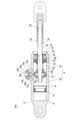
- FIG. 1 is a cross-sectional view showing a vehicle reinforcement member according to an embodiment of the present invention.
- 3 is an enlarged cross-sectional view showing a piston, a damping force generating portion and their vicinity.
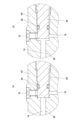
- FIG. 1 (a) is a diagram showing a state in which a bypass oil passage is closed by an adjustment valve, and (b) is a diagram showing a state in which the bypass oil passage is opened by the adjustment valve.
- 2A and 2B are schematic diagrams showing the flow of hydraulic oil in the embodiment of FIG. 1, in which FIG. 2A shows a case where a bypass oil passage is closed, and FIG. 2B shows a case where the bypass oil passage is opened.
- FIG. 1 is a diagram showing a two-wheeled vehicle in which a vehicle reinforcing member according to the present invention is used; 1 is a schematic diagram showing a four-wheeled vehicle in which a vehicle reinforcing member according to the present invention is used;
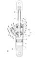
- FIG. 11 is a cross-sectional view showing a vehicle reinforcement member according to another embodiment of the present invention.
- (a) is a diagram showing a state in which the bypass oil passage is closed by the regulating valve
- (b) is a diagram showing a state in which the bypass oil passage is opened by the regulating valve.
- FIG. 11 is a cross-sectional view showing a vehicle reinforcement member according to another embodiment of the present invention.
- FIG. 7 is a diagram showing a two-wheeled vehicle in which a vehicle reinforcing member according to the present invention is used
- 1 is a schematic diagram showing a four-wheeled vehicle in which a vehicle reinforcing member according to the present invention is used
- FIG. 11 is a cross
- FIG. 11 is a cross-sectional view showing a vehicle reinforcement member according to still another embodiment of the present invention.
- a vehicle reinforcement member 10 is a single-tube hydraulic shock absorber.
- the vehicle reinforcement member 10 includes a cylinder 12 that is open at one end.
- a free piston 14, a piston 16, and a guide rod housing 18 are housed in the cylinder 12.
- the free piston 14 divides the inside of the cylinder 12 into a gas chamber G in which gas is sealed and an oil chamber H in which hydraulic oil is filled.
- An inert gas such as high-pressure nitrogen gas, is sealed in the gas chamber G.
- An O-ring 15 is provided between the free piston 14 and the cylinder 12.
- the piston 16 is capable of sliding in the axial direction X of the cylinder 12, and divides the oil chamber H into a first oil chamber H1 and a second oil chamber H2.
- the second oil chamber H2 is sandwiched between the gas chamber G and the first oil chamber H1.
- the stroke S of the piston 16 is short.
- the sliding range T of the piston 16 is not very large.
- the stroke S of the piston 16 is 1 mm or less, and the sliding range T of the piston 16 is about 10 mm.
- a piston ring 20 is attached to the outer circumferential surface of the piston 16, and an O-ring 22 is provided between the piston 16 and the piston ring 20.
- the piston 16 is provided with an extension-side damping force generating section 24a and a compression-side damping force generating section 24b to generate a damping force by flowing hydraulic oil between the first oil chamber H1 and the second oil chamber H2.
- the extension damping force generating section 24a includes an oil passage 26a and a damping valve 28a.
- the oil passage 26a penetrates the piston 16 to communicate the first oil chamber H1 and the second oil chamber H2.
- the damping valve 28a is configured by stacking a plurality of annular valve plates, and is provided on the main surface of the piston 16 on the second oil chamber H2 side so as to be able to open and close the oil passage 26a.
- the damping force generating section 24a functions when the piston 16 moves to the first oil chamber H1 side and the vehicle reinforcement member 10 extends.
- the compression damping force generating section 24b includes an oil passage 26b and a damping valve 28b.
- the oil passage 26b penetrates the piston 16 to communicate the first oil chamber H1 and the second oil chamber H2.
- the damping valve 28b is configured by stacking a plurality of annular valve plates, and is provided on the main surface of the piston 16 on the first oil chamber H1 side so as to be able to open and close the oil passage 26b.
- the damping force generating section 24b functions when the piston 16 moves to the second oil chamber H2 side and the vehicle reinforcement member 10 performs a compression operation.
- a piston rod 30 is attached to the piston 16 and fixed with a nut 32.
- a control washer 34 and a plain washer 36 are interposed between the damping valve 28b and the piston rod 30 on the first oil chamber H1 side of the piston 16, and a control washer 38 and a plain washer 40 are interposed between the damping valve 28a and the nut 32 on the second oil chamber H2 side of the piston 16.
- the guide rod housing 18 is provided near the open end in the cylinder 12 to guide the piston rod 30.
- the piston rod 30 attached to the piston 16 passes through the first oil chamber H1 and is inserted into the guide rod housing 18 to extend outside the cylinder 12.
- a slide metal 42 is inserted between the guide rod housing 18 and the piston rod 30. This allows the piston rod 30 to slide relative to the guide rod housing 18.
- a rod seal 44, a static seal 46, and a seal retainer 48 are provided on the first oil chamber H1 side of the guide rod housing 18, which seals between the cylinder 12 and the piston rod 30 to prevent oil from leaking from the first oil chamber H1.
- Circlips 50, 52 are provided in the cylinder 12, which fix the guide rod housing 18, the rod seal 44, the static seal 46, and the seal retainer 48 to predetermined positions in the cylinder 12.
- a dust seal 54 is provided on the outer main surface of the guide rod housing 18, which prevents foreign matter from entering the cylinder 12 from the outside.
- a spring 56 for canceling gas reaction force is provided between the plain washer 36 and the seal retainer 48.
- the other end of the piston rod 30 is screwed into a nut 58 to prevent loosening, and is screwed into a joint 60.
- the vehicle reinforcement member 10 further includes a damping force adjustment unit 62 that adjusts the damping force.
- the damping force adjustment unit 62 includes a housing portion 64 provided in the cylinder 12, a bypass oil passage 66 provided within the housing portion 64 and connecting the first oil chamber H1 and the second oil chamber H2 outside the sliding range T of the piston 16, and an adjustment valve 68 that changes the flow area of the bypass oil passage 66 to adjust the flow rate of hydraulic oil in the bypass oil passage 66.
- the housing portion 64 is integrally formed on the open end side of the cylinder 12.
- the bypass oil passage 66 includes a first passage 70 connected to the first oil chamber H1, a second passage 72 connected to the second oil chamber H2, and a third passage 74 connecting the first passage 70 and the second passage 72.
- the first passage 70 and the second passage 72 connect to the first oil chamber H1 and the second oil chamber H2, respectively, outside the sliding range T in the axial direction X.
- the first passage 70 intersects with the first oil chamber H1 at a right angle to the axial direction X
- the second passage 72 intersects with the second oil chamber H2 at a right angle to the axial direction X
- the third passage 74 is parallel to the axial direction X.
- the ends of the first passage 70 and the second passage 72 are blocked by plugs 76 and 78, respectively.
- the adjustment valve 68 is provided in the housing part 64 to change the flow area between the first passage 70 and the third passage 74.
- An O-ring 80 is fitted to the tip of the adjustment valve 68.
- a circlip 82 for preventing the adjustment valve 68 from coming off is attached near the head of the adjustment valve 68 in the housing part 64.
- a control handle 86 is fixed to the head of the adjustment valve 68 by a set screw 84, and the position of the adjustment valve 68 can be adjusted by the control handle 86.
- the vehicle reinforcement member 10 is applied to a motorcycle 100.
- the motorcycle 100 includes a vehicle body 102 and two wheels 104 provided on the vehicle body 102.
- the vehicle body 102 includes a frame 106 that is generally U-shaped in plan view and provided between the two wheels 104.
- the vehicle reinforcement member 10 connects two points on the front of the frame 106, two points on one side (left side) of the frame 106, and two points on the other side (right side) of the frame 106. In this manner, the vehicle reinforcement member 10 is attached between two points on the vehicle body 102.
- the vehicle reinforcement member 10 is applied to a four-wheeled vehicle 200.
- the four-wheeled vehicle 200 includes a vehicle body 202 and four wheels 204 provided on the vehicle body 202.
- the vehicle body 202 includes a pair of side members 206, 208 extending in the front-rear direction.
- the front ends and rear ends of the side members 206, 208 are connected to each other by the vehicle reinforcement member 10. In this manner, the vehicle reinforcement member 10 is attached between two points on the vehicle body 202.
- the hydraulic oil is caused to flow between the first oil chamber H1 and the second oil chamber H2 through the damping force generating parts 24a, 24b provided on the piston 16 in the cylinder 12, thereby generating a damping force.
- the first oil chamber H1 and the second oil chamber H2 are connected by a bypass oil passage 66 provided in the housing part 64 of the damping force adjustment part 62.
- the flow area of the bypass oil passage 66 is changed by the adjustment valve 68, and the flow rate of the hydraulic oil in the bypass oil passage 66 is adjusted, thereby increasing or decreasing the damping force. This allows the damping force setting to be changed according to the passenger's preference.
- bypass oil passage 66 when the bypass oil passage 66 is closed by the adjustment valve 68, the hydraulic oil passes through the damping force generating parts 24a, 24b provided on the piston 16 to generate a large damping force, but when the bypass oil passage 66 is opened by the adjustment valve 68, part of the hydraulic oil flows into the bypass oil passage 66, so that the damping force can be changed according to the opening amount of the adjustment valve 68.
- the bypass oil passage 66 communicates the first oil chamber H1 and the second oil chamber H2 outside the sliding range T of the piston 16, so that the piston 16 does not block the bypass oil passage 66 regardless of the position of the piston 16 in the cylinder 12, and the bypass oil passage 66 is always open to allow hydraulic oil to flow.
- the damping force set by the damping force adjustment unit 62 can always suppress minute deformations and vibrations that occur in the vehicle body 102, 202 when the vehicle is traveling.
- straight-line stability can be improved, and the degree of straight-line stability can be set according to the rider's preference by the damping force adjustment unit 62.
- the first path 70 and the second path 72 are formed to extend in a direction perpendicular to the axial direction X of the cylinder 12, and the third path 74 is formed to extend parallel to the axial direction X, so that the third path 74 can be easily formed from the first path 70.
- the vehicle reinforcement member 10 can be suitably used in vehicles such as two-wheeled vehicles 100 and four-wheeled vehicles 200.
- the vehicle reinforcement member 10a is configured similarly to the vehicle reinforcement member 10, except that it includes a damping force adjustment portion 62a instead of the damping force adjustment portion 62.
- the damping force adjustment unit 62a includes a housing portion 64a provided in the cylinder 12, a bypass oil passage 66a provided within the housing portion 64a and connecting the first oil chamber H1 and the second oil chamber H2 outside the sliding range T of the piston 16 (see FIG. 2), and an adjustment valve 68a that changes the flow area of the bypass oil passage 66a to adjust the flow rate of hydraulic oil in the bypass oil passage 66a.
- the housing portion 64a is integrally formed approximately at the center of the cylinder 12.
- the bypass oil passage 66a includes a first passage 70a that connects to the first oil chamber H1 and a second passage 72a that connects to the second oil chamber H2.
- the first passage 70a and the second passage 72a connect to the first oil chamber H1 and the second oil chamber H2, respectively, outside the sliding range T in the axial direction X.
- the first passage 70a intersects with the first oil chamber H1 at an obtuse angle with respect to the axial direction X
- the second passage 72a intersects with the second oil chamber H2 at an acute angle with respect to the axial direction X and communicates with the first passage 70a.
- the ends of the first passage 70a and the second passage 72a are blocked by plugs 76a and 78a, respectively.
- the adjusting valve 68a is a rotary valve provided in the housing portion 64a to change the flow path area between the first passage 70a and the second passage 72a.
- the adjusting valve 68a is provided to extend in a direction perpendicular to the axial direction X. By rotating the adjusting valve 68a, the bypass oil passage 66a is closed as shown in FIG. 8(a), or the bypass oil passage 66a is opened as shown in FIG. 8(b).
- the rest of the configuration of the vehicle reinforcement member 10a is the same as that of the vehicle reinforcement member 10, so a duplicated description will be omitted.
- the first passage 70a is formed to intersect with the first oil chamber H1 at an obtuse angle with respect to the axial direction X of the cylinder 12, and the second passage 72a is formed to intersect with the second oil chamber H2 at an acute angle with respect to the axial direction X, thereby shortening the oil passage length of the bypass oil passage 66a and reducing the size of the housing portion 64a provided in the cylinder 12.
- the flow path area between the first passage 70a and the second passage 72a can be easily adjusted by rotating the adjustment valve 68a, which is a rotary valve.
- the vehicle reinforcement member 10b is configured similarly to the vehicle reinforcement member 10, except that it includes a cylinder 12b and a damping force adjustment unit 62b instead of the cylinder 12 and the damping force adjustment unit 62.
- Cylinder 12b and cylinder 12 are slightly different in shape and size, but are essentially constructed the same.
- the damping force adjustment unit 62b includes a housing portion 64b provided in the cylinder 12b, a bypass oil passage 66b provided within the housing portion 64b and connecting the first oil chamber H1 and the second oil chamber H2 outside the sliding range T of the piston 16 (see FIG. 2), and an adjustment valve 68b that changes the flow area of the bypass oil passage 66b to adjust the flow rate of hydraulic oil in the bypass oil passage 66b.
- the housing portion 64b is integrally formed from the center of the cylinder 12b slightly toward the open end.
- the housing portion 64b has an opening 88b.
- the bypass oil passage 66b includes a first passage 70b that connects to the first oil chamber H1 and a second passage 72b that connects to the second oil chamber H2.
- the first passage 70b and the second passage 72b connect to the first oil chamber H1 and the second oil chamber H2, respectively, outside the sliding range T in the axial direction X.
- the first passage 70b connects the opening 88b to the first oil chamber H1
- the second passage 72b connects the opening 88b to the second oil chamber H2.
- the first passage 70b intersects with the first oil chamber H1 at an obtuse angle with respect to the axial direction X
- the second passage 72b intersects with the second oil chamber H2 at an obtuse angle with respect to the axial direction X.
- the adjustment valve 68b is provided in the housing part 64b to close the opening 88b and change the flow area between the first passage 70b and the second passage 72b.
- An O-ring 80b is fitted to the adjustment valve 68b.
- a circlip 82b for preventing the adjustment valve 68b from coming off is attached near the head of the adjustment valve 68b in the housing part 64b.
- a control handle 86b is fixed to the head of the adjustment valve 68b by a set screw 84b, and the position of the adjustment valve 68b can be adjusted by the control handle 86b.
- vehicle reinforcement member 10b The rest of the configuration of vehicle reinforcement member 10b is the same as vehicle reinforcement member 10, so a duplicated description will be omitted.
- both the first passage 70b and the second passage 72b can be easily processed from a single opening 88b in the housing portion 64b.
- the opening 88b in the housing portion 64b is blocked by the adjustment valve 68b, no separate plug is required, and the number of parts can be reduced.
- both the first passage 70b and the second passage 72b are formed to intersect with the oil chamber H at an obtuse angle with respect to the axial direction X of the cylinder 12b, the housing portion 64b provided in the cylinder 12b can be made smaller.
- the vehicle reinforcement member 10c is configured similarly to the vehicle reinforcement member 10b, except that it includes a damping force adjustment portion 62c instead of the damping force adjustment portion 62b.
- the damping force adjustment unit 62c includes a housing portion 64c provided in the cylinder 12b, a bypass oil passage 66c provided within the housing portion 64c and connecting the first oil chamber H1 and the second oil chamber H2 outside the sliding range T of the piston 16 (see FIG. 2), and an adjustment valve 68c that changes the flow area of the bypass oil passage 66c to adjust the flow rate of hydraulic oil in the bypass oil passage 66c.
- the housing portion 64c is integrally formed from the center of the cylinder 12b slightly toward the open end.
- the housing portion 64c has an opening 88c.
- the bypass oil passage 66c includes a first passage 70c that connects to the first oil chamber H1 and a second passage 72c that connects to the second oil chamber H2.
- the first passage 70c and the second passage 72c connect to the first oil chamber H1 and the second oil chamber H2, respectively, outside the sliding range T in the axial direction X.
- the first passage 70c connects the opening 88c to the first oil chamber H1
- the second passage 72c connects the opening 88c to the second oil chamber H2. Both the first passage 70c and the second passage 72c intersect with the oil chamber H at an acute angle with respect to the axial direction X.
- the adjustment valve 68c is provided in the housing part 64c to close the opening 88c and change the flow path area between the first passage 70c and the second passage 72c.
- An O-ring 80c is fitted to the adjustment valve 68c.
- a circlip 82c for preventing the adjustment valve 68c from coming off is attached near the head of the adjustment valve 68c in the housing part 64c.
- a control handle 86c is fixed to the head of the adjustment valve 68c by a set screw 84c, and the position of the adjustment valve 68c can be adjusted by the control handle 86c.
- the bypass oil passage 66c is opened and closed by moving the adjustment valve 68c back and forth.
- vehicle reinforcement member 10c The rest of the configuration of vehicle reinforcement member 10c is the same as vehicle reinforcement member 10b.
- both the first passage 70c and the second passage 72c can be easily processed from a single opening 88c in the housing portion 64c.
- the opening 88c in the housing portion 64c is blocked by the adjustment valve 68c, no separate plug is required, and the number of parts can be reduced.
- both the first passage 70c and the second passage 72c are formed to intersect with the oil chamber H at an acute angle with respect to the axial direction X of the cylinder 12b, the housing portion 64c provided in the cylinder 12b can be made smaller.
- the vehicle reinforcement members 10a to 10c can also be used effectively in vehicles such as two-wheeled vehicles and four-wheeled vehicles.
- the adjustment valve 68 is provided in the housing portion 64 to change the flow area between the first path 70 and the third path 74, but is not limited to this.
- the adjustment valve may be provided in the housing portion to change the flow area between the second path and the third path.
- both the first path 70b and the second path 72b are configured to intersect with the oil chamber H at an obtuse angle with respect to the axial direction X, but this is not limited to the above.
- the damping force adjustment section may be modified so that the first path intersects with the first oil chamber H1 at an obtuse angle with respect to the axial direction X, and the second path intersects with the second oil chamber H2 at an acute angle with respect to the axial direction X.
Landscapes
- Engineering & Computer Science (AREA)
- General Engineering & Computer Science (AREA)
- Mechanical Engineering (AREA)
- Fluid-Damping Devices (AREA)
Priority Applications (1)
| Application Number | Priority Date | Filing Date | Title |
|---|---|---|---|
| CN202380079104.3A CN120202362A (zh) | 2022-11-14 | 2023-06-12 | 车辆用加强部件和车辆 |
Applications Claiming Priority (2)
| Application Number | Priority Date | Filing Date | Title |
|---|---|---|---|
| JP2022182052A JP2024071218A (ja) | 2022-11-14 | 2022-11-14 | 車両用補強部材および車両 |
| JP2022-182052 | 2022-11-14 |
Publications (1)
| Publication Number | Publication Date |
|---|---|
| WO2024105913A1 true WO2024105913A1 (ja) | 2024-05-23 |
Family
ID=91084372
Family Applications (1)
| Application Number | Title | Priority Date | Filing Date |
|---|---|---|---|
| PCT/JP2023/021775 Ceased WO2024105913A1 (ja) | 2022-11-14 | 2023-06-12 | 車両用補強部材および車両 |
Country Status (4)
| Country | Link |
|---|---|
| JP (1) | JP2024071218A (https=) |
| CN (1) | CN120202362A (https=) |
| TW (1) | TW202423766A (https=) |
| WO (1) | WO2024105913A1 (https=) |
Families Citing this family (1)
| Publication number | Priority date | Publication date | Assignee | Title |
|---|---|---|---|---|
| JP2025166990A (ja) | 2024-04-25 | 2025-11-07 | 京セラドキュメントソリューションズ株式会社 | 画像形成装置 |
Citations (3)
| Publication number | Priority date | Publication date | Assignee | Title |
|---|---|---|---|---|
| JP2008008384A (ja) * | 2006-06-28 | 2008-01-17 | Nippon Yusoki Co Ltd | 油圧装置、及びこれを備えた産業車両の車輪懸架装置 |
| JP2010230099A (ja) * | 2009-03-27 | 2010-10-14 | Hitachi Automotive Systems Ltd | シリンダ装置 |
| JP2018079746A (ja) * | 2016-11-14 | 2018-05-24 | ヤマハ発動機株式会社 | 車両用補強部材および車両 |
-
2022
- 2022-11-14 JP JP2022182052A patent/JP2024071218A/ja active Pending
-
2023
- 2023-06-12 WO PCT/JP2023/021775 patent/WO2024105913A1/ja not_active Ceased
- 2023-06-12 CN CN202380079104.3A patent/CN120202362A/zh active Pending
- 2023-11-03 TW TW112142419A patent/TW202423766A/zh unknown
Patent Citations (3)
| Publication number | Priority date | Publication date | Assignee | Title |
|---|---|---|---|---|
| JP2008008384A (ja) * | 2006-06-28 | 2008-01-17 | Nippon Yusoki Co Ltd | 油圧装置、及びこれを備えた産業車両の車輪懸架装置 |
| JP2010230099A (ja) * | 2009-03-27 | 2010-10-14 | Hitachi Automotive Systems Ltd | シリンダ装置 |
| JP2018079746A (ja) * | 2016-11-14 | 2018-05-24 | ヤマハ発動機株式会社 | 車両用補強部材および車両 |
Also Published As
| Publication number | Publication date |
|---|---|
| TW202423766A (zh) | 2024-06-16 |
| JP2024071218A (ja) | 2024-05-24 |
| CN120202362A (zh) | 2025-06-24 |
Similar Documents
| Publication | Publication Date | Title |
|---|---|---|
| EP0508134B1 (en) | Wheel suspension system for bicycle | |
| US7997588B2 (en) | Cylinder apparatus and stabilizer apparatus using the same | |
| EP0980774B1 (en) | Suspension apparatus for vehicles | |
| US10384739B2 (en) | Control system of the trim of vehicles with more than two wheels | |
| US6332622B1 (en) | Suspension apparatus having two interconnected shock absorbers | |
| JP5289312B2 (ja) | 三輪または四輪のオートバイのトリムを制御するシステム | |
| JP2005024101A (ja) | ダンパ | |
| JP2014237362A (ja) | 鞍乗型車両 | |
| CN113498396A (zh) | 缓冲器 | |
| JP5761578B2 (ja) | 車両のサスペンション装置 | |
| WO2015037497A1 (ja) | 緩衝器 | |
| JPH0672127A (ja) | 4輪車用懸架装置 | |
| US7722061B2 (en) | Steering dampers and vehicles including same | |
| WO2024105913A1 (ja) | 車両用補強部材および車両 | |
| JP5549889B2 (ja) | 車両のサスペンション装置 | |
| US8439380B2 (en) | Front structure of saddle type vehicle | |
| JP6349116B2 (ja) | フロントフォーク | |
| US20060180416A1 (en) | Rotary damper | |
| JP4092219B2 (ja) | ステアリング装置 | |
| US20050127587A1 (en) | Hydraulic shock absorbing apparatus of vehicle | |
| WO2019014726A1 (en) | SUSPENSION DAMPING SYSTEM | |
| JP5486471B2 (ja) | 流体圧緩衝器 | |
| JP6533026B1 (ja) | 緩衝器 | |
| JP7419153B2 (ja) | エアサスペンション装置、及び、鞍乗り型車両 | |
| JP2008008384A (ja) | 油圧装置、及びこれを備えた産業車両の車輪懸架装置 |
Legal Events
| Date | Code | Title | Description |
|---|---|---|---|
| 121 | Ep: the epo has been informed by wipo that ep was designated in this application |
Ref document number: 23891075 Country of ref document: EP Kind code of ref document: A1 |
|
| WWE | Wipo information: entry into national phase |
Ref document number: 2501003141 Country of ref document: TH Ref document number: 202380079104.3 Country of ref document: CN |
|
| NENP | Non-entry into the national phase |
Ref country code: DE |
|
| WWP | Wipo information: published in national office |
Ref document number: 202380079104.3 Country of ref document: CN |
|
| 122 | Ep: pct application non-entry in european phase |
Ref document number: 23891075 Country of ref document: EP Kind code of ref document: A1 |