WO2024100795A1 - 車両の収納部 - Google Patents
車両の収納部 Download PDFInfo
- Publication number
- WO2024100795A1 WO2024100795A1 PCT/JP2022/041699 JP2022041699W WO2024100795A1 WO 2024100795 A1 WO2024100795 A1 WO 2024100795A1 JP 2022041699 W JP2022041699 W JP 2022041699W WO 2024100795 A1 WO2024100795 A1 WO 2024100795A1
- Authority
- WO
- WIPO (PCT)
- Prior art keywords
- wall portion
- vehicle
- storage compartment
- interior member
- wall
- Prior art date
- Legal status (The legal status is an assumption and is not a legal conclusion. Google has not performed a legal analysis and makes no representation as to the accuracy of the status listed.)
- Ceased
Links
Images




Classifications
-
- B—PERFORMING OPERATIONS; TRANSPORTING
- B60—VEHICLES IN GENERAL
- B60R—VEHICLES, VEHICLE FITTINGS, OR VEHICLE PARTS, NOT OTHERWISE PROVIDED FOR
- B60R7/00—Stowing or holding appliances inside vehicle primarily intended for personal property smaller than suit-cases, e.g. travelling articles, or maps
- B60R7/04—Stowing or holding appliances inside vehicle primarily intended for personal property smaller than suit-cases, e.g. travelling articles, or maps in driver or passenger space, e.g. using racks
Definitions
- This case concerns a pocket-shaped storage compartment formed in the interior material of the vehicle's cabin.
- a storage space in the passenger compartment for storing small items.
- a structure in which a drink holder and hooks for hanging luggage are formed on the instrument panel located in front of the driver's seat and passenger seat.
- a console box is placed on the floor between the driver's seat and passenger seat, allowing small items to be placed on the top and sides of the console box (see Patent Documents 1 and 2).
- One of the objectives of this case was devised in light of the above-mentioned problems, and is to provide a storage section for a vehicle that improves the convenience of storing items. However, this objective is not the only objective. Another objective of this case is to achieve effects that cannot be obtained with conventional technology, which are derived from the configurations shown in the "Mode for carrying out the invention" described below.
- the disclosed vehicle storage section can be realized as the aspects or application examples disclosed below, and solves at least a part of the above-mentioned problems.
- the disclosed storage section of a vehicle is a storage section formed in a pocket shape in an interior member inside a vehicle cabin, and includes an inner wall portion disposed inside the interior member and extending in a vertical direction, a bottom wall portion extending from a lower end of the inner wall portion toward the outside of the interior member, and an outer wall portion erected upward from an outer end of the interior member at the bottom wall portion and disposed opposite the inner wall portion.
- the bottom wall portion has a first surface portion formed as an inclined surface that inclines from the lower end of the inner wall portion toward the outside and downward of the interior member.
- the outer wall portion is formed to be lower in height than the inner wall portion, and is formed so that its upper end is located inside the interior member relative to the outer end of the bottom wall portion.
- the disclosed vehicle storage section can prevent items from flying out or falling, improving convenience.
- FIG. 1 is a schematic diagram showing a vehicle interior in which a storage unit of a vehicle according to an embodiment is arranged.
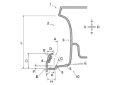
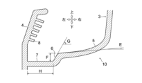
- FIG. FIG. 4 is an enlarged cross-sectional view showing a storage section. 4 is an enlarged cross-sectional view showing a lower portion of the storage section.
- FIG. 4 is a cross-sectional view showing a state in which the smartphone is stored in the storage section.
- FIG. 4 is a cross-sectional view of the storage section (a cross-sectional view taken along line AA in FIG. 3).
- the disclosed vehicle storage section is implemented, for example, in the following embodiment.
- This storage section is formed in a pocket shape in an interior member inside the vehicle cabin.
- Specific examples of interior members in which the storage section is formed include door trim, pillar trim, dashboard, console box, etc.
- the front-rear direction is determined based on the forward and backward direction of the vehicle
- the left-right direction is determined based on the front-rear direction.
- the up-down direction is determined based on the state in which the vehicle is stopped on a flat road surface. Note that the position and orientation of the storage section within the vehicle cabin can be assumed in a wide variety of ways. Therefore, when referring to directions related to the detailed structure of the storage section, the inward and outward directions of the interior member in which the storage section is formed are used as the reference.
- the reference direction is the inward direction of the door trim (towards the outside of the vehicle when viewed from inside the vehicle cabin) or the outward direction of the door trim (the direction from the door toward the vehicle cabin, towards the inside of the vehicle when viewed from inside the vehicle cabin).
- the reference direction is the inward direction of the dashboard (towards the outside of the vehicle when viewed from inside the vehicle cabin, towards the front) or the outward direction of the dashboard (towards the outside of the vehicle when viewed from inside the vehicle cabin, towards the rear).
- the reference direction is the inward direction or outward direction of the center console box.
- FIG. 1 is a schematic diagram showing the interior of a vehicle including a storage box 1 (interior member) in which a storage section 2 of a vehicle is formed as an embodiment.
- the storage box 1 is a center console box disposed between the driver's seat and the passenger seat, and is provided in the center of the vehicle in the vehicle width direction.
- the storage box 1 has a box-like shape with a relatively small dimension in the vehicle width direction and a relatively large dimension in the front-rear direction and the up-down direction.
- a selector lever, a shift lever, and switches are provided on the upper surface side of the storage box 1.
- a tray for placing small items, an armrest, etc. may be provided on the upper surface of the storage box 1.
- FIG. 2 is a cross-sectional view showing a cross section of the storage box 1 cut along a vertical plane whose normal direction is the front-rear direction.
- a storage section 2 that can be used as a storage space for small items, a smartphone 9, and other items is recessed into the side of the storage box 1 in the vehicle width direction.
- the storage section 2 has a shape in which the surface of the storage box 1 is recessed into a pocket shape toward the inside of the storage box 1.
- one storage section 2 is provided on each of the left and right sides of the storage box 1.
- One storage section 2 serves as a storage space for the occupant seated in the driver's seat, and the other storage section 2 serves as a storage space for the occupant seated in the passenger seat.
- Figure 3 is an enlarged cross-sectional view of the left storage section 2 of the storage section 2 shown in Figure 2.
- the storage section 2 has an inner wall 3, a bottom wall 10, and an outer wall 4.
- the inner wall 3 is a part of the storage section 2 that is located inside the storage box 1 (right side in Figure 3) and is formed in a shape that extends in the vertical direction.
- the inner wall 3 has a concave shape that is recessed toward the inside of the storage box 1.
- the bottom wall 10 extends from the lower end of the inner wall 3 toward the outside of the storage box 1 (left side in Figure 3) and forms the bottom of the storage section 2.
- the outer wall portion 4 is a portion that stands upright from the end of the bottom wall portion 10 on the outside of the storage box 1 (left side in Figure 3) and is positioned opposite the inner wall portion 3.
- the outer wall portion 4 is formed to be lower in height than the inner wall portion 3.
- the space above the outer wall portion 4 becomes an opening through which items pass when they are put in and taken out of the storage section 2.
- the outer wall portion 4 is formed with ribs 8 to increase rigidity.
- the ribs 8 stand upright from the inner surface of the outer wall portion 4 (the surface facing the inner wall portion 3) toward the inside of the storage box 1.
- the upper end of the outer wall 4 is formed so as to be located more inward (to the right in FIG. 3) than the outer end of the bottom wall 10.
- the outer end of the bottom wall 10 is defined as "part B".
- the outer wall 4 is formed so that its upper end is located more inward (to the right in FIG. 3) than part B.
- the outer wall 4 is formed so that its upper end is inclined upward and toward the inside of the storage section 2.
- the main part of the outer wall 4 is formed in a substantially upright state from part B, and only the upper end of the outer wall 4 is formed so as to be bent toward the inside of the storage section 2.
- the outer wall 4 may be generally inclined toward the inside of the storage section 2, with its upper end bent further inward.
- the bottom wall portion 10 includes a first surface portion 5, a step portion 6, and a second surface portion 7.
- the first surface portion 5 is a portion formed as an inclined surface that slopes from the lower end of the inner wall portion 3 toward the outside and downward of the storage box 1. It is preferable that the first surface portion 5 is formed as a curved surface that curves upward as it approaches the inside of the storage box 1, and forms a surface that is continuous with the inner wall portion 3. For example, as shown in Fig. 4, it is preferable to set the shape of the first surface portion 5 so that the inclination angle of the first surface portion 5 becomes steeper as it moves to the right in Fig. 4.
- the step portion 6 is a portion provided adjacent to the first surface portion 5 on the outside of the storage box 1.
- the step portion 6 is formed in a surface shape that is inclined downward and outward from the storage box 1 at a steeper slope than the first surface portion 5.
- the second surface portion 7 is a flat portion provided adjacent to the step portion 6 on the outside of the storage box 1, and is formed in a substantially horizontal plane.
- the second surface portion 7 is disposed outside the storage box 1 relative to the first surface portion 5, and is formed in a shape one step lower than the first surface portion 5.
- the step portion 6 is formed between the first surface portion 5 and the second surface portion 7.
- the outer wall portion 4 is formed so as to overlap above the second surface portion 7. In other words, the outer wall portion 4 is disposed so as to overlap the second surface portion 7 in a top view, and is formed so as to partially cover the second surface portion 7.
- the height dimension of the outer wall 4 when the position (height) of the portion B is taken as the reference is C
- the height dimension of the inner wall 3 when the portion B is taken as the reference is L
- the height dimension C of the outer wall 4 is set to be at least less than the height dimension L of the inner wall 3 (C ⁇ L) so that items can be easily put in and taken out. Also, if the height of the outer wall 4 is too short, items will easily fall out of the storage section 2. Therefore, the height dimension C of the outer wall 4 is set to, for example, 30 mm or more (30 mm ⁇ C).
- the height dimension L of the inner wall 3 is, for example, 60 mm or more (60 mm ⁇ L).
- the height dimension C of the outer wall 4 is at least half the height dimension L of the inner wall 3 and less than the height dimension L [(L/2) ⁇ C ⁇ L].
- the upper limit of the height dimension L of the inner wall 3 can be set appropriately depending on the size of the items to be stored in the storage section 2, and is not limited to a specific value, but it is preferable to set it within the range of, for example, about 60 to 300 mm.
- the inclination dimension of the upper end of the outer wall 4 when the position of part B is used as the reference is D.
- This inclination dimension D of the outer wall 4 into the inside of the storage box 1 is equal to the overlap dimension between the outer wall 4 and the second surface 7 (the inward and outward dimension of the storage box 1 in the area where the outer wall 4 and the second surface 7 overlap when viewed from above).
- the falling dimension D is at least half the width H of the second surface 7 (the dimension in the inward and outward directions of the storage box 1) [(H/2) ⁇ D].
- the width H of the second surface 7 is 10 mm, it is preferable that the falling dimension D is at least 5 mm. It is also preferable that the falling dimension D is equal to or less than the width H (D ⁇ H).
- the width H of the second surface 7 is not limited to a specific value, but it is preferable to set it within a range of, for example, 20 mm or less. This reduces the movement allowance (play) of an item placed on the second surface 7, and can suppress misalignment (wobbling in the inward and outward directions of the storage box 1).
- the inclination of the first surface portion 5 is set to at least 3° with respect to the horizontal plane.
- Angle E in FIGS. 3 and 4 indicates the minimum inclination angle of the first surface portion 5. It is preferable to set the shape of the first surface portion 5 so that this angle E is 3° or more. However, if angle E is too large, the items stored in the storage section 2 will easily slide over the surface of the first surface portion 5, reducing the ability to hold the items. For this reason, it is preferable to set angle E in the range of, for example, 20° or less.
- the height dimension F of the step portion 6 is 5 mm or more. This makes it easier to prevent an item stored in the storage section 2 from moving in the opposite direction when it moves from the first surface portion 5 to the second surface portion 7.
- the step portion 6 functions as a stopper that prevents an item supported on the second surface portion 7 from moving toward the first surface portion 5, even when acceleration is applied to the vehicle body.
- the upper limit of the height dimension F of the step portion 6 is not limited to a specific value. On the other hand, if the height dimension F of the step portion 6 is too large, there is a risk of excessive shock and noise when the item moves from the first surface portion 5 to the second surface portion 7. Therefore, it is preferable that the upper limit of the height dimension F of the step portion 6 is within a range of, for example, about 5 to 10 mm. In addition, it is preferable that the inclination angle G of the step portion 6 with respect to the horizontal plane is set within a range of 30° or more and 60° or less.
- Temporary smartphone placement position] 5 is a cross-sectional view of the storage section 2 for explaining the movement of the smartphone 9.
- the smartphone 9 When the smartphone 9 is placed at the position shown by the dashed line in FIG. 5, for example, due to the vehicle body vibration, the bottom of the smartphone 9 slides down along the upper surface of the first surface 5 and reaches the position shown by the dashed line. The bottom of the smartphone 9 then moves over the step portion 6 to the second surface 7, and the smartphone 9 stops at the position shown by the solid line. In this way, a temporary placement position of the smartphone 9 that makes the display screen easier to see for the occupant is realized.
- the angle of inclination of the smartphone 9 with respect to the horizontal plane increases, and there is a risk that the top of the smartphone 9 will climb over the outer wall 4 and fall.
- the angle of inclination of the smartphone 9 with respect to the horizontal plane is less likely to increase. In other words, the smartphone 9 becomes more likely to maintain the position shown by the solid line in FIG. 5, and the smartphone 9 is prevented from jumping out of the storage section 2 or falling.
- FIG. 6 is a cross-sectional view (A-A cross-sectional view in FIG. 3) showing a cross section of the second surface 7 of the storage box 1 cut along a vertical plane whose normal direction is the left-right direction.
- the front-to-rear length K of the second surface 7 is preferably formed to be shorter than the front-to-rear length J of the storage section 2 (K ⁇ J).
- the height of the second surface 7 and the first surface 5 may be raised to a height approximately equal to the height of the upper end of the outer wall 4. This makes it easy to lift the smartphone 9 by sliding the bottom of the smartphone 9 backwards. This makes it easier to remove the smartphone 9 placed in the storage section 2, further improving convenience.
- the vehicle storage section 2 of this embodiment is a pocket-shaped storage section 2 formed in a storage box 1 (interior member) in the passenger compartment of the vehicle, and includes an inner wall portion 3 disposed inside the storage box 1 and extending in the vertical direction, a bottom wall portion 10 extending from the lower end of the inner wall portion 3 toward the outside of the storage box 1, and an outer wall portion 4 erected upward from the outer end of the storage box 1 at the bottom wall portion 10 and disposed opposite the inner wall portion 3.
- the bottom wall portion 10 has a first surface portion 5 formed in an inclined surface that slopes from the lower end of the inner wall portion 3 toward the outside and downward of the storage box 1.
- the outer wall portion 4 is formed to be lower in height than the inner wall portion 3, and is formed so that its upper end is located more inward than the outer end (part B) of the bottom wall portion 10 in the storage box 1.
- the first surface 5 may be formed in a curved shape that curves upward as it approaches the inside of the storage box 1, and may form a surface that is continuous with the inner wall 3.
- This type of configuration is suitable for making the angle of inclination of the smartphone 9 shallower with respect to the horizontal plane when, for example, the smartphone 9 is leaned against the inner wall 3.
- the smartphone 9 is less likely to be in a nearly upright position (a state in which the angle of inclination is close to 90°), making it easier to slide the bottom of the smartphone 9 along the first surface 5. This can therefore improve convenience.
- the outer wall portion 4 may be formed so that at least the upper end side is inclined upward and toward the inside of the storage section 2. With this configuration, for example, the upper end of the outer wall portion 4 shown in FIG. 3 can be easily inserted further inside the storage box 1 (to the right in FIG. 3) than part B. This can prevent items stored in the storage section 2 from flying out or falling, improving the convenience of the storage section 2.
- the outer wall 4 may be formed with an upper end bent toward the inside of the storage section 2. Even with this configuration, for example, the upper end of the outer wall 4 shown in FIG. 3 can be easily inserted further inside the storage box 1 than part B (to the right in FIG. 3). This can prevent items stored in the storage section 2 from flying out or falling, improving the convenience of the storage section 2.
- the outer wall 4 may be generally inclined toward the inside of the storage section 2, while its upper end is bent further toward the inside of the storage section 2. With this configuration, the collapse dimension D can be reasonably increased, improving the effect of preventing items from flying out or falling.
- the inner wall 3 may be formed in a concave shape that is recessed toward the inside of the storage box 1. In this case, items are put in and taken out of the storage section 2 through an opening at the top of the outer wall 4, and because the inner wall 3 is concave, it is easier to put items in and take them out. This improves the convenience of the storage section 2.
- the outer wall 4 may have ribs 8 extending from the inner surface of the outer wall 4 toward the inside of the storage section 2 in order to increase rigidity. This increases the rigidity of the outer wall 4 and prevents deformation or damage to the outer wall 4. This increases the effectiveness of preventing items from flying out or falling, improving convenience.
- the bottom wall portion 10 may have a second surface portion 7 that is disposed outside the first surface portion 5 and is formed one step lower than the first surface portion 5.
- a step portion 6 may be formed between the first surface portion 5 and the second surface portion 7.
- the step portion 6 may be formed, for example, in the shape of a surface that slopes from the outside of the storage box 1 at the first surface portion 5 toward the outside and downward of the storage box 1 at a steeper slope than the first surface portion 5.
- the bottom of an item placed on the first surface 5 can be guided to the second surface 7, and the item can be held in a more stable position.
- a temporary placement position for the smartphone 9 can be realized that makes the display screen easier to see for the occupant.
- the bottom of the smartphone 9 is less likely to move above the step section 6 (towards the first surface 5), improving the stability of the smartphone 9 when temporarily placed.
- the outer wall 4 may be formed so as to overlap above the second surface 7.
- the inclination dimension D of the outer wall 4 (the overlap dimension between the outer wall 4 and the second surface 7) may be set to more than half the width H of the second surface 7.
- This configuration can reduce the movement allowance (play) of an item placed on the second surface 7. For example, it can suppress the positional deviation (wobbling in the inward and outward directions of the storage box 1) of the smartphone 9 shown by the solid line in FIG. 5. Therefore, convenience can be improved.
- the storage section 2 may be recessed into the side of a console box (storage box 1) that is disposed between the left and right seats of the vehicle. This allows passengers seated in the driver's seat and passenger seat to easily take items in and out of the storage section 2, making it more convenient to use.
- a console box storage box 1 that is disposed between the left and right seats of the vehicle. This allows passengers seated in the driver's seat and passenger seat to easily take items in and out of the storage section 2, making it more convenient to use.
- the storage section 2 formed in the storage box 1 is exemplified, but the location where the storage section 2 is formed is not limited to the storage box 1.
- the storage section 2 may be formed in the door trim, the pillar trim, or the dashboard.
- the storage section 2 may be formed in any interior member provided in the passenger compartment of the vehicle.
- each part of the storage section 2 in the above embodiment are merely examples and are not intended to be limited to the values mentioned above. Furthermore, it is sufficient for the storage section 2 to have an inner wall section 3, a bottom wall section 10, and an outer wall section 4; for example, the step section 6 may be omitted, the second surface section 7 may be omitted, and the rib 8 may be omitted.
- the storage section 2 By at least forming an inclined first surface section 5 on the bottom wall section 10, forming the height of the outer wall section 4 lower than the inner wall section 3, and positioning its upper end inside the interior member rather than the outer end section of the bottom wall section 10, a storage section 2 that achieves the same effects as the above embodiment can be realized.
- This technology can be used for pocket-shaped storage areas in interior components inside vehicle cabins, and can also be used in the manufacturing industry for vehicles equipped with storage areas.
- Storage box (interior material) 2 Storage section 3 Inner wall section 4 Outer wall section 5 First surface section 6 Step section 7 Second surface section 8 Rib 9 Smartphone (item) 10 Bottom wall B Part C Height dimension D Incline dimension E Angle F Height dimension G Incline angle H Width J Front-rear direction length K Front-rear direction length L Height dimension
Landscapes
- Engineering & Computer Science (AREA)
- Mechanical Engineering (AREA)
- Vehicle Step Arrangements And Article Storage (AREA)
Abstract
Description
開示の車両の収納部は、車両の車室内の内装部材にポケット状に形成される収納部であって、前記内装部材の内側に配置され上下方向に延びる内壁部と、前記内壁部の下端から前記内装部材の外側に向かって延びる底壁部と、前記底壁部における前記内装部材の外側の端部から上方に立設されて前記内壁部と対向配置される外壁部と、を備える。前記底壁部は、前記内壁部の下端から前記内装部材の外側かつ下方に向かって傾斜した傾斜面状に形成された第一面部を有する。前記外壁部は、前記内壁部よりも高さが低く形成されるとともに、その上端が前記底壁部の外側の端部よりも前記内装部材の内側に位置するように形成される。
図1は、実施例としての車両の収納部2が形成された収納ボックス1(内装部材)を含む車室内を示す模式図ある。ここでは、右ハンドル車両の助手席を取り外した状態で、収納ボックス1の左側面を眺めたときの様子が示されている。収納ボックス1は、運転席と助手席との間に配置されるセンターコンソールボックスであり、車室内の車幅方向中央に設けられる。収納ボックス1の概形は箱状であり、車幅方向の寸法が比較的小さく、前後方向及び上下方向の寸法が比較的大きく形成される。収納ボックス1の上面側には、例えばセレクタレバー,シフトレバー,スイッチ類が設けられる。収納ボックス1の上面に、小物を置くためのトレイやひじ掛け等を設けてもよい。
第一面部5は、内壁部3の下端から収納ボックス1の外側かつ下方に向かって傾斜した傾斜面状に形成された部位である。この第一面部5は、収納ボックス1の内側に行くほど上方に向かって湾曲した曲面状に形成され、内壁部3と連続した面を構成することが好ましい。例えば、図4に示すように、第一面部5の傾斜角度が図4中で右側に移動するにつれて急勾配になるように、第一面部5の形状を設定することが好ましい。
第二面部7は、段差部6に隣接して収納ボックス1の外側に設けられる平坦な部位であり、ほぼ水平な平面状に形成される。第二面部7は、第一面部5よりも収納ボックス1の外側に配置されて、第一面部5よりも一段低い形状に形成される。段差部6は、第一面部5と第二面部7との間に形成される。外壁部4は、第二面部7の上方にオーバーラップするよう形成される。すなわち、外壁部4は上面視で第二面部7に重なるように配置され、第二面部7を部分的に覆うように形成される。
図3において、部位Bの位置(高さ)を基準としたときの外壁部4の高さ寸法をCとし、部位Bを基準としたときの内壁部3の高さ寸法をLとする。外壁部4の高さ寸法Cは、物品の出し入れがしやすくなるように、少なくとも内壁部3の高さ寸法L未満とされる(C<L)。また、外壁部4の高さが短すぎると、物品が収納部2から落下しやすくなってしまう。そのため、外壁部4の高さ寸法Cは、例えば30mm以上とされる(30mm≦C)。
図5は、スマートフォン9の移動を説明するための収納部2の断面図である。図5中に破線で示す位置にスマートフォン9が置かれた場合、例えば車体振動等により、スマートフォン9の底部が第一面部5の上面に沿って滑り落ち、一点鎖線で示す位置に達する。その後、スマートフォン9の底部は段差部6を超えて第二面部7に移動し、スマートフォン9は実線で示す位置で停止する。このように、乗員から見て表示画面が見やすくなるようなスマートフォン9の仮置き姿勢が実現される。
(1)本実施例の車両の収納部2は、車両の車室内の収納ボックス1(内装部材)にポケット状に形成される収納部2であって、収納ボックス1の内側に配置され上下方向に延びる内壁部3と、内壁部3の下端から収納ボックス1の外側に向かって延びる底壁部10と、底壁部10における収納ボックス1の外側の端部から上方に立設されて内壁部3と対向配置される外壁部4とを備える。底壁部10は、内壁部3の下端から収納ボックス1の外側かつ下方に向かって傾斜した傾斜面状に形成された第一面部5を有する。また、外壁部4は、内壁部3よりも高さが低く形成されるとともに、その上端が底壁部10の外側の端部(部位B)よりも収納ボックス1の内側に位置するように形成される。
上記の実施例はあくまでも例示に過ぎず、本実施例で明示しない種々の変形や技術の適用を排除する意図はない。本実施例の各構成は、それらの趣旨を逸脱しない範囲で種々変形して実施できる。また、本実施例の各構成は必要に応じて取捨選択でき、あるいは、公知技術に含まれる各種構成と適宜組み合わせることができる。
2 収納部
3 内壁部
4 外壁部
5 第一面部
6 段差部
7 第二面部
8 リブ
9 スマートフォン(物品)
10 底壁部
B 部位
C 高さ寸法
D 倒れ込み寸法
E 角度
F 高さ寸法
G 傾斜角度
H 幅
J 前後方向長さ
K 前後方向長さ
L 高さ寸法
Claims (9)
- 車両の車室内の内装部材にポケット状に形成される収納部であって、
前記内装部材の内側に配置され上下方向に延びる内壁部と、前記内壁部の下端から前記内装部材の外側に向かって延びる底壁部と、前記底壁部における前記内装部材の外側の端部から上方に立設されて前記内壁部と対向配置される外壁部と、を備え、
前記底壁部は、前記内壁部の下端から前記内装部材の外側かつ下方に向かって傾斜した傾斜面状に形成された第一面部を有し、
前記外壁部は、前記内壁部よりも高さが低く形成されるとともに、その上端が前記底壁部の外側の端部よりも前記内装部材の内側に位置するように形成される
ことを特徴とする、車両の収納部。 - 前記第一面部は、前記内装部材の内側に行くほど上方に向かって湾曲した曲面状に形成され、前記内壁部と連続した面を構成する
ことを特徴とする、請求項1に記載の車両の収納部。 - 前記外壁部は、少なくとも上端側が上方かつ前記収納部の内側に向かって傾斜した形状に形成される
ことを特徴とする、請求項1又は2に記載の車両の収納部。 - 前記外壁部は、上端部が前記収納部の内側へ屈曲した形状に形成される
ことを特徴とする、請求項1~3のいずれか一項に記載の車両の収納部。 - 前記内壁部は、前記内装部材の内側へ向かって凹む凹面状に形成され、
前記外壁部の上部が、前記収納部への物品の出し入れに係る開口となる
ことを特徴とする、請求項1~4のいずれか一項に記載の車両の収納部。 - 前記外壁部が、剛性を高めるべく前記外壁部の内側面から前記収納部の内側に向かって立設されるリブを有する
ことを特徴とする、請求項1~5のいずれか一項に記載の車両の収納部。 - 前記底壁部は、前記第一面部の外側に配置され同第一面部より一段低く形成された第二面部を有し、
前記第一面部と前記第二面部との間には、段差部が形成されている
ことを特徴とする、請求項1~6のいずれか一項に記載の車両の収納部。 - 前記外壁部が、前記第二面部の上方にオーバーラップするように形成され、
前記外壁部と前記第二面部とのラップ寸法が、前記第二面部の幅の半分以上である
ことを特徴とする、請求項7に記載の車両の収納部。 - 前記車両の左右シートの間に配置されるコンソールボックスの側面に凹設される
ことを特徴とする、請求項1~8のいずれか一項に記載の車両の収納部。
Priority Applications (2)
| Application Number | Priority Date | Filing Date | Title |
|---|---|---|---|
| JP2024556913A JP7747229B2 (ja) | 2022-11-09 | 2022-11-09 | 車両の収納部 |
| PCT/JP2022/041699 WO2024100795A1 (ja) | 2022-11-09 | 2022-11-09 | 車両の収納部 |
Applications Claiming Priority (1)
| Application Number | Priority Date | Filing Date | Title |
|---|---|---|---|
| PCT/JP2022/041699 WO2024100795A1 (ja) | 2022-11-09 | 2022-11-09 | 車両の収納部 |
Publications (1)
| Publication Number | Publication Date |
|---|---|
| WO2024100795A1 true WO2024100795A1 (ja) | 2024-05-16 |
Family
ID=91032496
Family Applications (1)
| Application Number | Title | Priority Date | Filing Date |
|---|---|---|---|
| PCT/JP2022/041699 Ceased WO2024100795A1 (ja) | 2022-11-09 | 2022-11-09 | 車両の収納部 |
Country Status (2)
| Country | Link |
|---|---|
| JP (1) | JP7747229B2 (ja) |
| WO (1) | WO2024100795A1 (ja) |
Citations (5)
| Publication number | Priority date | Publication date | Assignee | Title |
|---|---|---|---|---|
| JPS5956142U (ja) * | 1982-10-07 | 1984-04-12 | いすゞ自動車株式会社 | コンソ−ルボツクス |
| JP2003191794A (ja) * | 2001-12-27 | 2003-07-09 | Toyota Auto Body Co Ltd | コンソールボックスの物入れ取付構造 |
| KR20130058826A (ko) * | 2011-11-28 | 2013-06-05 | 한일이화주식회사 | 차량용 센터 콘솔 |
| JP2015051698A (ja) * | 2013-09-06 | 2015-03-19 | 本田技研工業株式会社 | 車両用収納トレイ |
| JP2021008157A (ja) * | 2019-06-28 | 2021-01-28 | ダイハツ工業株式会社 | コンソールボックス |
-
2022
- 2022-11-09 WO PCT/JP2022/041699 patent/WO2024100795A1/ja not_active Ceased
- 2022-11-09 JP JP2024556913A patent/JP7747229B2/ja active Active
Patent Citations (5)
| Publication number | Priority date | Publication date | Assignee | Title |
|---|---|---|---|---|
| JPS5956142U (ja) * | 1982-10-07 | 1984-04-12 | いすゞ自動車株式会社 | コンソ−ルボツクス |
| JP2003191794A (ja) * | 2001-12-27 | 2003-07-09 | Toyota Auto Body Co Ltd | コンソールボックスの物入れ取付構造 |
| KR20130058826A (ko) * | 2011-11-28 | 2013-06-05 | 한일이화주식회사 | 차량용 센터 콘솔 |
| JP2015051698A (ja) * | 2013-09-06 | 2015-03-19 | 本田技研工業株式会社 | 車両用収納トレイ |
| JP2021008157A (ja) * | 2019-06-28 | 2021-01-28 | ダイハツ工業株式会社 | コンソールボックス |
Also Published As
| Publication number | Publication date |
|---|---|
| JP7747229B2 (ja) | 2025-10-01 |
| JPWO2024100795A1 (ja) | 2024-05-16 |
Similar Documents
| Publication | Publication Date | Title |
|---|---|---|
| US8016338B2 (en) | Seat-form storage apparatus | |
| JP2003291733A (ja) | 自動車の後部荷室構造 | |
| US7600811B2 (en) | Cushion table structure of passenger seat | |
| CN106476704A (zh) | 集成的座椅靠背存储部 | |
| US12472876B2 (en) | Sliding transport apparatus of storage portion for vehicle | |
| US12370934B2 (en) | Table device | |
| JP7747229B2 (ja) | 車両の収納部 | |
| CN111094070B (zh) | 车辆的收纳结构 | |
| JP5004008B2 (ja) | 車両の荷室構造 | |
| JP5004009B2 (ja) | 車両の荷室構造 | |
| CN101574945B (zh) | 汽车内室的内饰件 | |
| JP6599928B2 (ja) | 側方衝撃補強を備える支持構造を有するコンソールアセンブリ | |
| US10414316B2 (en) | Container holder for a trim panel | |
| JP3744493B2 (ja) | 自動車用カップホルダー | |
| JP6385012B2 (ja) | ドア用容器ホルダ | |
| JP2008155680A (ja) | 自動車の後部荷室構造 | |
| KR102663948B1 (ko) | 암레스트 받침장치가 구비된 자동차용 무빙 콘솔박스 | |
| KR100657701B1 (ko) | 확장가능한 차량의 콘솔 박스 | |
| JP2010052653A (ja) | 車両用サイドライニングの配設構造 | |
| JP6769167B2 (ja) | ドアトリム及び車両用ドア | |
| JP4528060B2 (ja) | 自動車 | |
| JP3912040B2 (ja) | 車両用荷室構造 | |
| JP2024015753A (ja) | 車両の天井収納構造 | |
| WO2022202673A1 (ja) | 車両のシートベルトリトラクタ取付構造 | |
| JPH0316771Y2 (ja) |
Legal Events
| Date | Code | Title | Description |
|---|---|---|---|
| 121 | Ep: the epo has been informed by wipo that ep was designated in this application |
Ref document number: 22965120 Country of ref document: EP Kind code of ref document: A1 |
|
| DPE1 | Request for preliminary examination filed after expiration of 19th month from priority date (pct application filed from 20040101) | ||
| WWE | Wipo information: entry into national phase |
Ref document number: 2024556913 Country of ref document: JP |
|
| WWE | Wipo information: entry into national phase |
Ref document number: 2501002768 Country of ref document: TH |
|
| NENP | Non-entry into the national phase |
Ref country code: DE |
|
| 122 | Ep: pct application non-entry in european phase |
Ref document number: 22965120 Country of ref document: EP Kind code of ref document: A1 |