WO2024095570A1 - インダクタ部品 - Google Patents
インダクタ部品 Download PDFInfo
- Publication number
- WO2024095570A1 WO2024095570A1 PCT/JP2023/030260 JP2023030260W WO2024095570A1 WO 2024095570 A1 WO2024095570 A1 WO 2024095570A1 JP 2023030260 W JP2023030260 W JP 2023030260W WO 2024095570 A1 WO2024095570 A1 WO 2024095570A1
- Authority
- WO
- WIPO (PCT)
- Prior art keywords
- wiring
- coil
- external electrode
- inductor component
- main surface
- Prior art date
- Legal status (The legal status is an assumption and is not a legal conclusion. Google has not performed a legal analysis and makes no representation as to the accuracy of the status listed.)
- Ceased
Links
Images
















Classifications
-
- H—ELECTRICITY
- H01—ELECTRIC ELEMENTS
- H01F—MAGNETS; INDUCTANCES; TRANSFORMERS; SELECTION OF MATERIALS FOR THEIR MAGNETIC PROPERTIES
- H01F27/00—Details of transformers or inductances, in general
- H01F27/28—Coils; Windings; Conductive connections
- H01F27/29—Terminals; Tapping arrangements for signal inductances
- H01F27/292—Surface mounted devices
-
- H—ELECTRICITY
- H01—ELECTRIC ELEMENTS
- H01F—MAGNETS; INDUCTANCES; TRANSFORMERS; SELECTION OF MATERIALS FOR THEIR MAGNETIC PROPERTIES
- H01F17/00—Fixed inductances of the signal type
-
- H—ELECTRICITY
- H01—ELECTRIC ELEMENTS
- H01F—MAGNETS; INDUCTANCES; TRANSFORMERS; SELECTION OF MATERIALS FOR THEIR MAGNETIC PROPERTIES
- H01F17/00—Fixed inductances of the signal type
- H01F17/0006—Printed inductances
- H01F17/0013—Printed inductances with stacked layers
-
- H—ELECTRICITY
- H01—ELECTRIC ELEMENTS
- H01F—MAGNETS; INDUCTANCES; TRANSFORMERS; SELECTION OF MATERIALS FOR THEIR MAGNETIC PROPERTIES
- H01F27/00—Details of transformers or inductances, in general
- H01F27/28—Coils; Windings; Conductive connections
- H01F27/29—Terminals; Tapping arrangements for signal inductances
-
- H—ELECTRICITY
- H01—ELECTRIC ELEMENTS
- H01F—MAGNETS; INDUCTANCES; TRANSFORMERS; SELECTION OF MATERIALS FOR THEIR MAGNETIC PROPERTIES
- H01F17/00—Fixed inductances of the signal type
- H01F17/0006—Printed inductances
- H01F17/0013—Printed inductances with stacked layers
- H01F2017/002—Details of via holes for interconnecting the layers
Definitions
- This disclosure relates to inductor components.
- the inductor component has an element body, a coil provided within the element body and wound along the axial direction, and a first external electrode and a second external electrode provided on the element body and electrically connected to the coil.
- the coil has multiple coil patterns stacked along the axis. Adjacent coil patterns in the axial direction are connected via conductive vias.
- the coil pattern has a wiring portion extending in a direction perpendicular to the axis, and a pad portion provided at the end of the wiring portion and connecting to the conductive via. The width of the pad portion is wider than the width of the wiring portion to improve the connectivity between the pad portion and the conductive via.
- the width of the pad portion is wider than the width of the wiring portion, so part of the pad portion is located radially inside the coil relative to the wiring portion. This makes the inner diameter of the coil smaller, and the efficiency of obtaining inductance is not necessarily high.
- the present disclosure therefore aims to provide an inductor component that can increase the efficiency of obtaining inductance.
- an inductor component comprises: an element body including a first main surface and a second main surface opposed to each other; a coil, at least a portion of which is provided inside the element body and which is wound helically along an axis; a first external electrode and a second external electrode provided outside the element body and electrically connected to the coil; Equipped with The axis of the coil is disposed parallel to the first major surface;
- the coil is a plurality of first coil wirings provided on the first main surface side with respect to the axis and arranged along the axis on a plane parallel to the first main surface; a plurality of second coil wirings provided on the second main surface side with respect to the axis and arranged along the axis on a plane parallel to the second main surface; a plurality of first through wires extending from the first coil wiring toward the second coil wiring and arranged along the axis; a plurality of second through wirings extending from the first coil wiring toward the second coil
- the coil includes a first coil wiring, a first through wiring, a second coil wiring, and a second through wiring, and the first coil wiring, the first through wiring, the second coil wiring, and the second through wiring are connected in this order to form at least a part of a spiral shape, so that the inner diameter of the coil can be increased and the efficiency of obtaining inductance can be increased. Also, by increasing the efficiency of obtaining inductance, the Q value can be increased. Furthermore, since the first external electrode has a convex portion protruding in the first direction, the surface area is increased compared to when the first external electrode is flat without a convex portion, and the strength of the adhesion to a connection member such as solder can be improved.
- the convex portion of the first external electrode is in contact with the endmost coil wiring, and the first external electrode and the endmost coil wiring are directly connected. This makes it possible to reduce the DC resistance (Rdc) compared to when the first external electrode and the endmost coil wiring are connected by, for example, via wiring.
- the thickness of the first external electrode is smaller than the thickness of the first coil wiring.
- the thickness of the inductor component can be reduced.
- the body includes SiO2 .
- the first external electrode is composed of a plurality of conductive layers, including a conductive layer made of a different material from the conductive layer that constitutes the endmost coil wiring.
- the first external electrode further includes a bottom portion that is provided continuously from the first portion of the convex portion on the side opposite the second portion and extends in a direction parallel to the first main surface, and a wall portion that is provided continuously from the bottom portion and extends in the first direction.
- the surface area of the first external electrode is further increased, and the strength of adhesion to a connecting member such as solder can be further improved.
- the first external electrode further includes a fourth portion spaced apart from the second portion and positioned closer to the first direction than the second portion.
- the fourth portion is located on the first direction side of the second portion, the surface area of the first external electrode is further increased, and the strength of adhesion to a connecting member such as solder can be further improved.
- the first main surface has a recess
- the recess has a stepped side surface
- At least a portion of the first external electrode is in contact with the side surface and is shaped to fit along the side surface.
- the surface area of the first external electrode is further increased, and the strength of adhesion to a connecting member such as solder can be further improved.
- the inductor component Further comprising an insulator provided on a portion of the first main surface, At least a portion of the first external electrode is in continuous contact with the insulator, the first main surface, and the first side surface of the protrusion.
- the first external electrode can be given an uneven shape, which can further improve the strength of adhesion to a connecting member such as solder.
- the first coil wiring is provided on the first main surface,
- the coil wiring is covered with an insulator having a shape conforming to the shape of the first coil wiring.
- At least a portion of the first external electrode is in contact with the insulator and is shaped to conform to the shape of the first coil wiring.
- At least a portion of the first external electrode is shaped to conform to the shape of the first coil wiring, which further increases the surface area of the first external electrode and further improves the bonding strength with a connecting member such as solder.
- the inductor component Further comprising an organic insulator provided on the first main surface,
- the element body is an inorganic insulator, and the organic insulator is located inside an outer surface of the inorganic insulator when viewed in a direction perpendicular to the first main surface.
- the organic insulator since the organic insulator is included, the organic insulator is easily given fluidity, and when the first coil wiring is covered with the organic insulator, the organic insulator can be easily filled between adjacent first coil wirings, improving insulation. In addition, since the organic insulator is not in contact with the outer surface of the inorganic insulator, the load on the organic insulator can be reduced when singulating into individual inductor components, and deformation and peeling of the organic insulator can be suppressed.
- the first through wire and the second through wire are not parallel to each other.
- the distance between the first through-hole wiring and the second through-hole wiring can be increased, the inner diameter of the coil can be increased, and the Q value can be increased.
- the body includes SiO2
- the first through-hole contains SiO2 .
- the linear expansion coefficient of the first through-hole wiring can be matched to the linear expansion coefficient of the element body, thereby suppressing cracks between the first through-hole wiring and the element body.
- the first through-wire includes a void portion or a resin portion.
- the stress caused by the difference in linear expansion coefficient between the first through wiring and the element body can be absorbed by the void portion or the resin portion, thereby alleviating the stress.
- the first through wiring has a conductive layer located on the outer periphery side when viewed from the extending direction of the first through wiring, and a non-conductive layer located inside the conductive layer.
- the current when used in the high frequency band, the current mainly flows through the surface of the first through-hole wiring due to the skin effect, so by providing a conductive layer on the outer periphery, the Q value is not lowered.
- the Q value when provided on the outer periphery, the Q value is not lowered.
- by providing a non-conductive layer on the inside stress can be alleviated, and manufacturing costs can be reduced by not using a conductor.
- the axial length of the coil is less than the inner diameter of the coil.
- the coil length is short and the coil inner diameter is large, so the Q value can be increased.
- the first through-hole wiring extends in a direction perpendicular to the first main surface, A cross-sectional area of at least one of both end portions in the extension direction of the first through wiring is larger than a cross-sectional area of a central portion in the extension direction of the first through wiring.
- the cross-sectional area of the end of the first through wiring can be increased, improving the connectivity between the first through wiring and at least one of the first coil wiring and the second coil wiring.
- the cross-sectional area of the end of the first through wiring is large and the cross-sectional area of the center of the first through wiring is small, it is easy to form the first through wiring.
- the coil component has a thickness of 200 ⁇ m or less.
- the inductor components can be made thinner.
- the first external electrode and the second external electrode are located inside the outer surface of the element body.
- the first external electrode and the second external electrode are not in contact with the outer surface of the element body, so that when the inductor components are singulated, the load on the first external electrode and the second external electrode can be reduced, and deformation and peeling of the first external electrode and the second external electrode can be suppressed. Therefore, even if the inductor component is made small, deformation and peeling of the first external electrode and the second external electrode can be prevented.
- the inductor component according to one aspect of the present disclosure can improve the efficiency of obtaining inductance.
- FIG. 2 is a schematic bottom view of the inductor component of the first embodiment as viewed from the bottom side.
- FIG. This is a cross-sectional view of FIG.
- FIG. 3 is a cross-sectional view taken along line III-III of FIG.
- FIG. 4 is an enlarged view of part A in FIG. 3 .
- 5A to 5C are schematic cross-sectional views illustrating a method for manufacturing an inductor component.
- 5A to 5C are schematic cross-sectional views illustrating a method for manufacturing an inductor component.
- 5A to 5C are schematic cross-sectional views illustrating a method for manufacturing an inductor component.
- 5A to 5C are schematic cross-sectional views illustrating a method for manufacturing an inductor component.
- 5A to 5C are schematic cross-sectional views illustrating a method for manufacturing an inductor component.
- 5A to 5C are schematic cross-sectional views illustrating a method for manufacturing an inductor component.
- 5A to 5C are schematic cross-sectional views illustrating a method for manufacturing an inductor component.
- 5A to 5C are schematic cross-sectional views illustrating a method for manufacturing an inductor component.
- 5A to 5C are schematic cross-sectional views illustrating a method for manufacturing an inductor component.
- 5A to 5C are schematic cross-sectional views illustrating a method for manufacturing an inductor component.
- 5A to 5C are schematic cross-sectional views illustrating a method for manufacturing an inductor component.
- 5A to 5C are schematic cross-sectional views illustrating a method for manufacturing an inductor component.
- 5A to 5C are schematic cross-sectional views illustrating a method for manufacturing an inductor component.
- 5A to 5C are schematic cross-sectional views illustrating a method for manufacturing an inductor component.
- 5A to 5C are schematic cross-sectional views illustrating a method for manufacturing an inductor component.
- FIG. 11 is a cross-sectional view showing a first modified example of an inductor component.
- FIG. 11 is a cross-sectional view showing a second modified example of the inductor component.
- FIG. 11 is a cross-sectional view showing a third modified example of the inductor component.
- FIG. 11 is a cross-sectional view showing a first modified example of an inductor component.
- FIG. 11 is a cross-sectional view showing a second modified example of the inductor component.
- FIG. 11 is a cross-sectional view showing a third modified
- FIG. 11 is a cross-sectional view showing a fourth modified example of the inductor component.
- FIG. 11 is a cross-sectional view showing a fifth modified example of the inductor component.
- 13 is a schematic bottom view of the inductor component of the second embodiment as viewed from the bottom side.
- FIG. 8 is a cross-sectional view taken along line VIII-VIII of FIG. 7.
- FIG. 9 is an enlarged view of part A in FIG. 8 .
- 5A to 5C are schematic cross-sectional views illustrating a method for manufacturing an inductor component.
- 5A to 5C are schematic cross-sectional views illustrating a method for manufacturing an inductor component.
- 5A to 5C are schematic cross-sectional views illustrating a method for manufacturing an inductor component.
- 5A to 5C are schematic cross-sectional views illustrating a method for manufacturing an inductor component.
- 5A to 5C are schematic cross-sectional views illustrating a method for manufacturing an inductor component.
- 5A to 5C are schematic cross-sectional views illustrating a method for manufacturing an inductor component.
- 5A to 5C are schematic cross-sectional views illustrating a method for manufacturing an inductor component.
- 5A to 5C are schematic cross-sectional views illustrating a method for manufacturing an inductor component.
- 5A to 5C are schematic cross-sectional views illustrating a method for manufacturing an inductor component.
- 1 is a schematic cross-sectional view showing a first modified example of an inductor component.
- 13 is a schematic cross-sectional view showing a second modified example of the inductor component.
- FIG. FIG. 13 is a schematic cross-sectional view showing a third modified example of the inductor component.
- Fig. 1 is a schematic bottom view of the inductor component 1 as viewed from the bottom side.
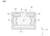
- Fig. 2 is a cross-sectional view taken along line II-II in Fig. 1.
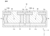
- Fig. 3 is a cross-sectional view taken along line III-III in Fig. 1.
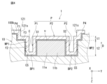
- Fig. 4 is an enlarged view of part A in Fig. 3.
- external electrodes are depicted by two-dot chain lines in Fig. 1.
- the element body 10 is depicted as transparent so that the structure can be easily understood, but it may be semi-transparent or opaque.
- the inductor component 1 is a surface mount type inductor component used, for example, in a high frequency signal transmission circuit. As shown in Figures 1 to 4, the inductor component 1 includes an element body 10, a coil 110 at least a portion of which is provided inside the element body 10 and wound in a spiral shape along an axis AX, and a first external electrode 121 and a second external electrode 122 provided outside the element body 10 and electrically connected to the coil 110.
- the element body 10 has a length, width, and height.
- the element body 10 has a first end face 100e1 and a second end face 100e2 at both ends in the length direction, a first side face 100s1 and a second side face 100s2 at both ends in the width direction, and a bottom face 100b and a top face 100t at both ends in the height direction.
- the outer surface 100 of the element body 10 includes the first end face 100e1 and the second end face 100e2, the first side face 100s1 and the second side face 100s2, the bottom face 100b, and the top face 100t.
- the bottom face 100b corresponds to an example of a "first main face” as described in the claims
- the top face 100t corresponds to an example of a "second main face” as described in the claims.
- the length direction (longitudinal direction) of the element body 10 is referred to as the X direction.
- the direction from the first end face 100e1 to the second end face 100e2 is referred to as the forward X direction, and the opposite direction of the forward X direction is referred to as the reverse X direction.
- the width direction of the element body 10 is referred to as the Y direction.
- the direction from the first side face 100s1 to the second side face 100s2 is referred to as the forward Y direction, and the opposite direction of the forward Y direction is referred to as the reverse Y direction.
- the height direction of the element body 10 is referred to as the Z direction.
- the direction from the bottom face 100b to the top face 100t is referred to as the forward Z direction, and the opposite direction of the forward Z direction is referred to as the reverse Z direction.
- the X direction, Y direction, and Z direction are mutually perpendicular directions, and when arranged in the order of X, Y, Z, they form a right-handed system.
- the direction from the top face 100t side to the bottom face 100b side is referred to as the first direction D1.
- the first direction D1 includes not only a direction parallel to the Z direction, but also a direction tilted from a direction parallel to the Z direction. In this embodiment, the first direction D1 is the reverse Z direction.
- the "outer surface 100 of the element body” including the first end surface 100e1, the second end surface 100e2, the first side surface 100s1, the second side surface 100s2, the bottom surface 100b, and the top surface 100t of the element body 10 does not simply mean a surface facing the outer periphery of the element body 10, but a surface that is the boundary between the outside and the inside of the element body 10. Furthermore, “above the outer surface 100 of the element body 10” does not mean an absolute direction such as vertically upward as defined by the direction of gravity, but refers to a direction toward the outside of the outside and the inside with the outer surface 100 as a boundary, based on the outer surface 100. Therefore, "above the outer surface 100” is a relative direction determined by the orientation of the outer surface 100. Furthermore, "above” with respect to a certain element includes not only an upper side away from the element, that is, an upper position through another object on the element or an upper position with a space therebetween, but also a position directly above the element (on).
- the axis AX of the coil 110 is arranged parallel to the bottom surface 100b.
- the coil 110 includes a plurality of bottom wirings 11b arranged on the bottom surface 100b side with respect to the axis AX and arranged along the axis AX on a plane parallel to the bottom surface 100b, a plurality of top wirings 11t arranged on the top surface 100t side with respect to the axis AX and arranged along the axis AX on a plane parallel to the top surface 100t, a plurality of first through wirings 13 extending from the bottom wirings 11b toward the top wirings 11t and arranged along the axis AX, and a plurality of second through wirings 14 extending from the bottom wirings 11b toward the top wirings 11t, arranged on the opposite side of the axis AX to the first through wirings 13, and arranged along the axis AX.
- the plurality of bottom wirings 11b include an endmost coil wiring 11e located on one side in the axis AX direction.
- the two bottom wirings 11b located at both ends in the AX direction are the endmost coil wirings 11e.
- the bottom wiring 11b, the first through wiring 13, the top wiring 11t, and the second through wiring 14 are connected in this order to form at least a part of a spiral shape.
- the bottom wiring 11b corresponds to an example of the "first coil wiring” described in the claims
- the top wiring 11t corresponds to an example of the "second coil wiring” described in the claims.
- the axis AX is the intersection of a first plane passing through the center between the bottom wiring 11b and the top wiring 11t, and a second plane passing through the center between the first through wiring 13 and the second through wiring 14.
- the axis AX is a straight line passing through the center of the inner diameter portion of the coil 110.
- the axis AX of the coil 110 has no dimension in a direction perpendicular to the axis AX.
- the coil 110 includes the bottom wiring 11b, the first through wiring 13, the top wiring 11t, and the second through wiring 14.
- the bottom wiring 11b, the first through wiring 13, the top wiring 11t, and the second through wiring 14 are connected in this order to form at least a part of a spiral shape, so that the inner diameter of the coil 110 can be increased and the efficiency of obtaining inductance can be increased. Furthermore, by increasing the efficiency of obtaining inductance, the Q value can be increased.
- the pad portion of a conventional inductor component and the bottom wiring 11b and top wiring 11t of this embodiment are "receiving portions" for the wiring that penetrates the element body (the conductive vias of a conventional inductor component and the first through wiring 13 and second through wiring 14 of this embodiment), and therefore have a shape that extends perpendicularly in the direction that penetrates the element body.
- the pad portion extends in a direction perpendicular to the axis of the coil, and is likely to have a structure that blocks magnetic flux generated in the axial direction of the coil.
- the first through wiring 13 and the second through wiring 14 extend in a direction perpendicular to the axis AX of the coil 110, so the bottom wiring 11b and the top wiring 11t extend in a direction parallel to the axis AX of the coil 110. Therefore, the bottom wiring 11b and the top wiring 11t are unlikely to have a structure that blocks magnetic flux generated in the direction of the axis AX. In other words, with this embodiment, a structure that is unlikely to block magnetic flux can be achieved, improving the inductance acquisition efficiency and Q value.
- the endmost coil wiring 11e which is located on the first end face 100e1 side with respect to the center of the element body 10 in the X direction, has an upper surface u located on the first direction D1 side, and a first side surface S1 and a second side surface S2 located on both sides of a center line CL along the extension direction of the endmost coil wiring 11e when viewed from a direction perpendicular to the bottom surface 100b (Z direction).
- the first external electrode 121 includes a first portion P1 that contacts at least a part of the first side surface S1 of the endmost coil wiring 11e, a second portion P2 that contacts at least a part of the upper surface u of the endmost coil wiring 11e, and a third portion P3 that contacts at least a part of the second side surface S2 of the endmost coil wiring 11e.
- the first portion P1, the second portion P2, and the third portion P3 are successively arranged in this order to form a protrusion P that protrudes in the first direction D1 side.
- the endmost coil wiring 11e which is located on the second end face 100e2 side with respect to the center of the element body 10 in the X direction, has an upper surface u located on the first direction D1 side, and a first side surface S1 and a second side surface S2 located on both sides of a center line CL along the extension direction of the endmost coil wiring 11e when viewed from a direction perpendicular to the bottom surface 100b (Z direction).
- the second external electrode 122 includes a first portion that contacts at least a portion of the first side surface S1 of the endmost coil wiring 11e, a second portion that contacts at least a portion of the upper surface u of the endmost coil wiring 11e, and a third portion that contacts at least a portion of the second side surface S2 of the endmost coil wiring 11e.
- the first portion, second portion, and third portion are successively arranged in this order to form a protrusion P that protrudes in the first direction D1 side.
- the first external electrode 121 and the second external electrode 122 have a protrusion P protruding in the first direction D1, which increases the surface area compared to when the electrodes are flat without the protrusion P, thereby improving the strength of adhesion to a connecting member such as solder.
- the protrusion P of the first external electrode 121 and the second external electrode 122 is in contact with the endmost coil wiring 11e, and each of the first external electrode 121 and the second external electrode 122 is directly connected to the endmost coil wiring 11e. This makes it possible to reduce the DC resistance (Rdc) compared to when each of the first external electrode 121 and the second external electrode 122 is connected to the endmost coil wiring 11e using, for example, via wiring.
- the volume of the inductor component 1 is preferably 0.08 mm3 or less, and the size of the long side of the inductor component 1 is 0.65 mm or less.
- the size of the long side of the inductor component 1 refers to the largest value among the length, width, and height of the inductor component 1, and in this embodiment, refers to the length in the X direction. According to the above configuration, the volume of the inductor component 1 is small and the long side of the inductor component 1 is also short, so that the weight of the inductor component 1 is light. Therefore, even if the external electrodes 121 and 122 are small, the necessary mounting strength can be obtained.
- the thickness of the inductor component 1 is preferably 200 ⁇ m or less. This allows the inductor component 1 to be made thin.
- the size of the inductor component 1 (length (X direction) x width (Y direction) x height (Z direction)) is 0.6 mm x 0.3 mm x 0.3 mm, 0.4 mm x 0.2 mm x 0.2 mm, 0.25 mm x 0.125 mm x 0.120 mm, etc. Furthermore, the width and height do not have to be equal, and may be, for example, 0.4 mm x 0.2 mm x 0.3 mm.
- the element body 10 preferably contains SiO2 . This can provide insulation and rigidity to the element body 10.
- the element body 10 is made of, for example, a sintered glass body.
- the sintered glass body may contain alumina, which can further increase the strength of the element body.
- the glass sintered body is formed, for example, by stacking multiple insulating layers containing glass.
- the stacking direction of the multiple insulating layers is the Z direction.
- the insulating layers are in a layered form having main surfaces extending in the XY plane. Note that, due to firing or the like, the interfaces between the multiple insulating layers of the element body 10 may not be clear.
- the element body 10 may be made of, for example, a glass substrate.
- the glass substrate may be a single-layer glass substrate, and since the majority of the element body is made of glass, losses such as eddy current losses at high frequencies can be suppressed.
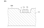
- a recess C is provided on the bottom surface 100b of the element body 10. Specifically, the recess C is provided in each of the two endmost coil wirings 11e such that the connection portion with the first external electrode 121 or the second external electrode 122 is exposed from the element body 10.
- the shape of the recess C when viewed from the Z direction is not particularly limited as long as the connection portion is exposed from the element body 10, but in this embodiment, it is rectangular.
- the coil 110 includes a plurality of bottom wirings 11b, a plurality of top wirings 11t, a plurality of first through wirings 13, and a plurality of second through wirings 14.
- the bottom wirings 11b, the first through wirings 13, the top wirings 11t, and the second through wirings 14 are connected in sequence to form at least a portion of the coil 110 wound in the axial direction AX.
- the coil 110 is a so-called helical-shaped coil 110, so that in a cross section perpendicular to the axis AX, the area in which the bottom wiring 11b, the top wiring 11t, the first through wiring 13, and the second through wiring 14 run parallel to the winding direction of the coil 110 can be reduced, thereby reducing the stray capacitance in the coil 110.
- a helical shape refers to a shape in which the number of turns in the entire coil is greater than one turn, and the number of turns in the coil in a cross section perpendicular to the axis is less than one turn.
- One turn or more refers to a state in which, in a cross section perpendicular to the axis, the coil wiring has parts that are adjacent in the radial direction when viewed from the axial direction and run parallel to the winding direction
- “less than one turn” refers to a state in which, in a cross section perpendicular to the axis, the coil wiring does not have parts that are adjacent in the radial direction when viewed from the axial direction and run parallel to the winding direction.
- the bottom wiring 11b extends in only one direction. Specifically, the bottom wiring 11b extends in the Y direction at a slight incline toward the X direction.
- the multiple bottom wirings 11b are arranged parallel to each other along the X direction.
- modified illumination such as annular illumination or dipole illumination
- the pattern resolution in a specific direction can be improved to form a finer pattern.
- fine bottom wiring 11b can be formed by using modified illumination in the photolithography process, for example, and the inductor component 1 can be made smaller.
- the bottom wirings 11b include the end coil wiring 11e located at the end on one side of the axis AX direction.
- one end of the end coil wiring 11e in the extension direction (in other words, the connection part with the first external electrode 121 or the second external electrode 122) is arranged in a recess C provided on the bottom surface 100b of the element body 10 and is exposed from the element body 10.
- the end connected to the first external electrode 121 or the second external electrode 122 is arranged in the recess C and exposed from the element body 10.
- the entire end coil wiring 11e may be arranged in the recess C and exposed from the element body 10. In this case, it is preferable that the first external electrode 121 or the second external electrode 122 contacts the entire exposed surface of the end coil wiring 11e (in other words, the entire first side surface s1, the entire second side surface s2, and the entire upper surface u).
- the top surface wiring 11t extends in only one direction. Specifically, the top surface wiring 11t extends in the Y direction. The multiple top surface wirings 11t are arranged in parallel along the X direction. With the above configuration, since the top surface wiring 11t extends in only one direction, by using, for example, modified illumination in the photolithography process, it is possible to form fine top surface wiring 11t and reduce the size of the inductor component 1.
- the bottom wiring 11b and the top wiring 11t are made of a good conductor material such as copper, silver, gold, or an alloy of these.
- the bottom wiring 11b and the top wiring 11t may be a metal film formed by plating, vapor deposition, sputtering, or the like, or may be a metal sintered body formed by applying and sintering a conductive paste.
- the bottom wiring 11b and the top wiring 11t may also be a multi-layer structure in which multiple metal layers are stacked.
- the thickness of the bottom wiring 11b and the top wiring 11t is preferably 5 ⁇ m or more and 50 ⁇ m or less.
- the first through wiring 13 is disposed on the first side surface 100s1 side of the axis AX within the through hole V of the element body 10, and the second through wiring 14 is disposed on the second side surface 100s2 side of the axis AX within the through hole V of the element body 10.
- the first through wiring 13 and the second through wiring 14 each extend in a direction perpendicular to the bottom surface 100b and the top surface 100t. This allows the lengths of the first through wiring 13 and the second through wiring 14 to be shortened, thereby suppressing the direct current resistance (Rdc).
- the multiple first through wirings 13 and the multiple second through wirings 14 are each disposed in parallel along the X direction.
- the first through wiring 13 contains SiO 2. According to this, when the element body 10 contains SiO 2 , the linear expansion coefficient of the first through wiring 13 can be matched to the linear expansion coefficient of the element body 10, and cracks between the first through wiring 13 and the element body 10 can be suppressed.
- a conductive paste is used for the first through wiring 13.
- the conductive material is Ag, Cu, or the like.
- the second through wiring 14 similarly contains SiO 2 .
- At least one of the bottom wiring 11b, top wiring 11t, first through wiring 13, and second through wiring 14 includes a void portion or a resin portion.
- a void portion or a resin portion This allows the stress caused by the difference in linear expansion coefficient between the wiring and the element body 10 to be absorbed by the void portion or resin portion, and the stress can be alleviated.
- a method for forming the void portion for example, a material that is burned away by sintering is used as the wiring material, and the void portion can be formed by sintering the wiring.
- a method for forming the resin portion for example, a conductive paste can be used as the wiring material to form the resin portion.
- At least one of the bottom surface wiring 11b and the top surface wiring 11t contains SiO 2.
- the linear expansion coefficient of the wiring can be matched to the linear expansion coefficient of the element body 10, and cracks between the wiring and the element body 10 can be suppressed.
- the first external electrode 121 is connected to a first end of the coil 110, and the second external electrode 122 is connected to a second end of the coil 110.
- the first external electrode 121 is provided on the first end face 100e1 side with respect to the center of the element body 10 in the X direction so as to be exposed from the outer surface 100 of the element body 10.
- the second external electrode 122 is provided on the second end face 100e2 side with respect to the center of the element body 10 in the X direction so as to be exposed from the outer surface 100 of the element body 10.
- the outer surface 100 of the element body 10 includes the inner surface of the recess C.
- this "outside” also includes the area inside the recess C. In other words, the area inside the recess C is considered to be the outside of the element body 10.
- the first external electrode 121 may be provided continuously on the bottom surface 100b and the first end surface 100e1. In this way, since the first external electrode 121 is a so-called L-shaped electrode, a solder fillet can be formed on the first external electrode 121 when the inductor component 1 is mounted on a mounting board. Similarly, the second external electrode 122 may be provided continuously on the bottom surface 100b and the second end surface 100e2.
- the first external electrode 121 has an underlayer 121e1 and a plating layer 121e2 that covers the underlayer 121e1.
- the underlayer 121e1 includes a conductive material such as Cu, Ni, Ti, or a combination of these.
- the plating layer 121e2 includes a conductive material such as Ni or Au.
- the second external electrode 122 has an underlayer and a plating layer that covers the underlayer. Note that the first external electrode 121 and the second external electrode 122 may be composed of a single layer of conductive material.
- the first external electrode 121 is arranged to cover the entire recess C provided on the bottom surface 100b of the element body 10 when viewed from the Z direction. As a result, the first external electrode 121 contacts the entire surface of the first side surface S1 of the endmost coil wiring 11e that is exposed from the element body 10, contacts the entire surface of the upper surface u of the endmost coil wiring 11e that is exposed from the element body 10, and contacts the entire surface of the second side surface S2 of the endmost coil wiring 11e that is exposed from the element body 10. As a result, the first external electrode 121 has a protrusion P at a position corresponding to the exposed portion of the endmost coil wiring 11e from the element body 10. The first external electrode 121 has a step 121s that corresponds to the step of the recess C (the first surface described later).
- the second external electrode 122 is arranged to cover the entire recess C provided on the bottom surface 100b of the element body 10 when viewed from the Z direction.
- the second external electrode 122 contacts the entire surface of the first side surface S1 of the endmost coil wiring 11e that is exposed from the element body 10, contacts the entire surface of the upper surface u of the endmost coil wiring 11e that is exposed from the element body 10, and contacts the entire surface of the second side surface S2 of the endmost coil wiring 11e that is exposed from the element body 10.
- the second external electrode 122 has a protrusion P at a position corresponding to the portion of the endmost coil wiring 11e that is exposed from the element body 10.
- the second external electrode 122 has a step 122s that corresponds to the step of the recess C.
- the thickness t1 of the first external electrode 121 in the Z direction is smaller than the thickness t2 of the bottom wiring 11b in the Z direction.
- the thickness of the first external electrode 121 refers to the thickness in all layers. Even if the thickness of the first external electrode 121 is reduced, the effect on the DC resistance (Rdc) is small. Therefore, according to the above configuration, the thickness of the inductor component 1 can be reduced while suppressing an increase in the DC resistance. More preferably, the thickness t1 of the first external electrode 121 is 1/2 or less of the thickness t2 of the bottom wiring 11b. This allows the thickness of the inductor component 1 to be reduced more effectively.
- the thickness of the second external electrode 122 may also be smaller than the thickness of the bottom wiring 11b.
- the first external electrode 121 is composed of multiple conductive layers, including a conductive layer made of a different material from the conductive layer that makes up the end coil wiring 11e.
- the end coil wiring 11e may be made of a conductive layer with high conductivity, such as Cu or Ag.
- the first external electrode 121 may be made of a conductive layer that has good adhesion to the end coil wiring 11e, such as Ti, a conductive layer with high electromigration resistance, such as Ni, a conductive layer with high corrosion resistance, such as Au, or a conductive layer with high solder wettability. This configuration allows the first external electrode 121 to be given characteristics different from those of the end coil wiring 11e.
- the second external electrode 122 is composed of multiple conductive layers, and may include a conductive layer made of a different material from the conductive layer that makes up the end coil wiring 11e.
- the first external electrode 121 further includes a bottom portion BP1 that is provided continuously from the first portion P1 of the protrusion P to the opposite side to the second portion P2 and extends in a direction parallel to the bottom surface 100b (Y direction), and a wall portion WP1 that is provided continuously from the bottom portion BP1 and extends in the first direction D1.
- a connection member such as solder
- the first external electrode 121 further includes a bottom portion BP2 that is provided continuously from the third portion P3 of the protrusion P to the opposite side to the second portion P2 and extends in a direction parallel to the bottom surface 100b, and a wall portion WP2 that is provided continuously from the bottom portion BP2 and extends in the first direction D1.
- a connection member such as solder
- the second external electrode 122 may further include a bottom portion that is continuous from at least one of the first and third portions of the protrusion P to the side opposite the second portion and extends in a direction parallel to the bottom surface 100b, and a wall portion that is continuous from the bottom portion and extends in the first direction D1.
- the first external electrode 121 further includes a fourth portion P4 that is separated from the second portion P2 and is located on the first direction D1 side of the second portion P2.
- the fourth portion P4 is a portion of the first external electrode 121 that is provided on the bottom surface 100b excluding the recess C.
- the surface area of the first external electrode 121 can be further increased.
- the shape of the first external electrode 121 between the second portion P2 and the fourth portion P4 can be made concave.
- the fourth portion P4 is located on the first direction D1 side of the second portion P2, the depth of the concave shape can be made deeper than when the fourth portion P4 is located on the opposite side of the first direction D1 (the forward Z direction side) of the second portion P2.
- the surface area of the first external electrode 121 can be more effectively increased, and the strength of adhesion to a connection member such as solder can be further improved.
- the second external electrode 122 may further include a fourth portion that is spaced apart from the second portion and is located closer to the first direction D1 than the second portion.
- the bottom surface 100b has a recess C
- the recess C has a step-shaped side surface CS
- at least a portion of the first external electrode 121 is in contact with the side surface CS and is shaped along the side surface CS.
- the side surface CS has a first surface f1 extending along the Z direction, a second surface f2 extending along the Z direction, and a third surface f3 connecting the first surface f1 and the second surface f2 and extending along the XY plane.
- the first surface f1 is disposed on the opening side of the recess C
- the second surface f2 is disposed on the bottom side of the recess C.
- the width of the first surface f1 in the Y direction is larger than the width of the second surface f2 in the Y direction.
- the width of the first surface f1 in the X direction is larger than the width of the second surface f2 in the X direction.
- the first surface f1, the second surface f2, and the third surface f3 constitute the step shape of the side surface CS.
- the number of steps of the step shape is not particularly limited. This configuration can further increase the surface area of the first external electrode 121, and further improve the strength of the connection with a connecting member such as solder.
- at least a portion of the second external electrode 122 may be in contact with the step-shaped side surface of the recess C and shaped to fit the side surface.
- Figures 5A to 5G, 5I, 5K, and 5M are views corresponding to the cross section II-II of Figure 1.
- Figures 5H, 5J, 5L, 5N, and 5O are views corresponding to the cross section III-III of Figure 1.
- a first insulating layer 1011 is provided on a base substrate 1000 by printing.
- the material of the base substrate 1000 is, for example, a glass substrate, a silicon substrate, an alumina substrate, etc.
- the material of the first insulating layer 1011 is, for example, a resin such as epoxy or polyimide, or an inorganic insulating film such as SiO or SiN.
- the second insulating layer 1012 is provided on the first insulating layer 1011 by printing.
- a groove 1012a is provided in the second insulating layer 1012.
- the groove 1012a is formed, for example, by a photolithography process. Note that the groove may be formed from the beginning as a printing pattern.
- a top conductor layer 1011t is provided in the groove 1012a by printing.
- the material of the top conductor layer 1011t is, for example, Ag, Cu, Au, Al, an alloy containing at least one of these elements, solder paste, etc.
- the top conductor layer 1011t is formed as a printing pattern so that it remains only in the groove 1012a. Note that after the top conductor layer 1011t is printed on the second insulating layer 1012, a photolithography process may be used to make the top conductor layer 1011t remain only in the groove 1012a.
- a third insulating layer 1013 is provided on the second insulating layer 1012 by printing.
- a first groove 1013a and a second groove 1013b are provided in the third insulating layer 1013.
- the first groove 1013a and the second groove 1013b are formed in the same manner as in FIG. 5B.
- the first through conductor layer 1131 of the first layer is provided by printing in the first groove 1013a
- the second through conductor layer 1141 of the first layer is provided by printing in the second groove 1013b.
- the first through conductor layer 1131 of the first layer and the second through conductor layer 1141 of the first layer are formed in the same manner as in FIG. 5C.
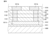
- a fourth insulating layer 1014 is provided on the third insulating layer 1013, and a second-layer first penetrating conductor layer 1132 and a second-layer second penetrating conductor layer 1142 are provided in each of the two grooves provided in the fourth insulating layer 1014. Furthermore, a fifth insulating layer 1015 is provided on the fourth insulating layer 1014, and a third-layer first penetrating conductor layer 1133 and a third-layer second penetrating conductor layer 1143 are provided in each of the two grooves provided in the fifth insulating layer 1015.
- a sixth insulating layer 1016 is provided on the fifth insulating layer 1015, and a bottom conductor layer 1011b is provided in a groove provided in the sixth insulating layer 1016.
- the material of the bottom conductor layer 1011b is the same as the material of the top conductor layer 1011t.
- FIG. 5H shows the same process as FIG. 5G.
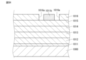
- a groove 1016a is provided in the sixth insulating layer 1016, and a bottom conductor layer 1011b is provided in the groove 1016a.
- the groove 1016a becomes part of the recess C.
- a seventh insulating layer 1017 is provided on the sixth insulating layer 1016.
- a groove is provided in the seventh insulating layer 1017 so that at least the portion of the bottom conductor layer 1011b that is connected to the first and second external electrodes is exposed.
- FIG. 5J shows the same process as FIG. 5I.
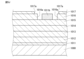
- a groove 1017a is provided in the seventh insulating layer 1017.
- the groove 1017a becomes part of the recess C.
- the size of the opening of the groove 1017a is made larger than the size of the opening of the groove 1016a. This allows a staircase shape to be formed on the side of the recess C.
- the entire laminate is sintered in a high-temperature (e.g., 500° C. or higher) furnace.
- the first to seventh insulating layers 1011-1017 are sintered to form the base body 10
- the top conductor layer 1011t is sintered to form the top wiring 11t
- the bottom conductor layer 1011b is sintered to form the bottom wiring 11b
- the first through conductor layers 1131-1133 of the first to third layers are sintered to form the first through wiring 13
- the second through conductor layers 1141-1143 of the first to third layers are sintered to form the second through wiring 14.
- the strength can be improved by sintering the insulating layers, and the conductor layers are sintered to volatilize unnecessary resin components contained in the conductor layers and fuse the conductor material contained in the conductor layers to achieve high conductivity.
- the base substrate 1000 may be peeled off by decomposing the surface during sintering, or may be mechanically removed by grinding or the like before or after sintering, or may be chemically removed by etching or the like before or after sintering.
- Figure 5L shows the same process as Figure 5K. As shown in Figure 5L, the above sintering results in the formation of an element body 10 with a recess C on the bottom surface 100b.
- a conductive material such as Cu, Ni, Ti, or a combination thereof is formed by sputtering, and then etched into a predetermined shape by photolithography to form a base layer 121e1.
- the predetermined shape is such that the base layer 121e1 covers at least the inner surface of the recess C.
- a plating layer 121e2 is formed by electroless plating so as to cover the base layer 121e1.
- the plating layer 121e2 is, for example, Ni/Au. In this manner, the external electrodes 121 and 122 are formed.
- FIG. 5N shows the same process as FIG. 5M. As shown in FIG.
- the first external electrode 121 comes into contact with the exposed portion of the end coil wiring 11e from the element body 10, and a convex portion P is formed on the first external electrode 121.
- the second external electrode 122 comes into contact with the exposed portion of the end coil wiring 11e from the element body 10, and a convex portion P is formed on the second external electrode 122.
- the chip is cut into individual pieces along cut lines D. This produces inductor component 1 as shown in FIG. 3.
- FIG. 6A is a view showing a first modified example of an inductor component corresponding to the III-III cross section in Fig. 1.
- the element body 10 is not provided in an area on the forward Y direction side and in an area on the reverse Y direction side of a portion of the endmost coil wiring 11e exposed from the element body 10. This makes it easier to bring the first external electrode 121 into contact with the bottom surface 100b of the element body 10.
- FIG. 6B is a view showing a second modified example of the inductor component, corresponding to the cross section taken along line II-II in Fig. 1.
- the first through wire 13 and the second through wire 14 are not parallel when viewed from a direction parallel to the axis AX of the coil 110. This makes it possible to increase the distance between the first through wire 13 and the second through wire 14, thereby making it possible to increase the inner diameter of the coil 110 and improve the Q value.
- the first through wiring 13 and the second through wiring 14 are bent at the center so that the distance between them becomes wider toward the center in the Z direction.
- the first through wiring 13 and the second through wiring 14 each have a shape that spreads outward in the radial direction of the coil 110 toward the center in the Z direction.
- the first through wiring 13 and the second through wiring 14 each have a stepped shape along the Z direction. According to the above configuration, when the first through wiring 13 and the second through wiring 14 are each formed by stacking multiple conductor layers, the first through wiring 13 and the second through wiring 14 can be easily formed in a stepped shape by stacking the conductor layers of each layer in a shifted manner.
- FIG. 6C is a view showing a third modified example of an inductor component corresponding to the cross section taken along line II-II in Fig. 1.
- the first through wire 13 and the second through wire 14 are not parallel when viewed from a direction parallel to the axis AX of the coil 110. This makes it possible to increase the distance between the first through wire 13 and the second through wire 14, thereby making it possible to increase the inner diameter of the coil 110 and improve the Q value.
- the first through wiring 13 and the second through wiring 14 are inclined so that the distance between them becomes wider toward the top wiring 11t in the Z direction.
- the first through wiring 13 and the second through wiring 14 each have a shape that spreads outward in the radial direction of the coil 110 as far as the top wiring 11t in the Z direction.
- the coil 110 has a trapezoidal shape when viewed from the axis AX direction.
- FIG. 6D is a view showing a fourth modified example of an inductor component corresponding to the cross section taken along line II-II in Fig. 1.
- an inductor component 1D of the fourth modified example includes a first coil 110A and a second coil 110B, as compared with the inductor component 1B of the second modified example shown in Fig. 6B.
- the first through-wire 13 and the second through-wire 14 are not parallel when viewed from a direction parallel to the axis AX. This allows the distance between the first through-wire 13 and the second through-wire 14 to be increased, the inner diameter of the coil 110A to be increased, and the Q value to be improved.
- the first through wiring 13 has the same configuration as the first through wiring 13 of the inductor component 1B of the second modified example.
- the second through wiring 14 has a linear shape parallel to the Z direction. In other words, the first through wiring 13 is bent at the center so that the distance between the first through wiring 13 and the second through wiring 14 becomes wider toward the center in the Z direction.
- the first through wiring 13 has a stepped shape along the Z direction. According to the above configuration, when the first through wiring 13 is formed by stacking multiple conductor layers, the first through wiring 13 can be easily formed in a stepped shape by stacking the conductor layers of each layer in a shifted manner.
- the first through-wire 13 and the second through-wire 14 are not parallel when viewed from a direction parallel to the axis AX. This allows the distance between the first through-wire 13 and the second through-wire 14 to be increased, the inner diameter of the coil 110B to be increased, and the Q value to be improved.
- the second through wiring 14 has the same configuration as the second through wiring 14 of the inductor component 1B of the second modified example.
- the first through wiring 13 has a linear shape parallel to the Z direction.
- the second through wiring 14 is bent at the center so that the distance between the first through wiring 13 and the second through wiring 14 becomes wider toward the center in the Z direction.
- the second through wiring 14 has a stepped shape along the Z direction. According to the above configuration, when the second through wiring 14 is formed by stacking multiple conductor layers, the second through wiring 14 can be easily formed in a stepped shape by stacking the conductor layers of each layer in a shifted manner.
- FIG. 6E is a view showing a fifth modified example of an inductor component corresponding to the cross section taken along line II-II in Fig. 1.
- inductor component 1E of the fifth modified example includes a first coil 110A and a second coil 110B, as compared with inductor component 1C of the third modified example shown in Fig. 6C.
- the first through-wire 13 and the second through-wire 14 are not parallel when viewed from a direction parallel to the axis AX. This allows the distance between the first through-wire 13 and the second through-wire 14 to be increased, the inner diameter of the coil 110A to be increased, and the Q value to be improved.
- the first through wiring 13 has the same configuration as the first through wiring 13 of the inductor component 1C of the third modified example.
- the second through wiring 14 has a linear shape parallel to the Z direction. In other words, the first through wiring 13 is inclined so that the distance between the first through wiring 13 and the second through wiring 14 becomes wider in the Z direction toward the top surface wiring 11t. With the above configuration, the first through wiring 13 and the second through wiring 14 can be formed in a linear shape and shortened, thereby reducing the DC resistance of the first through wiring 13 and the second through wiring 14.
- the first through-wire 13 and the second through-wire 14 are not parallel when viewed from a direction parallel to the axis AX. This allows the distance between the first through-wire 13 and the second through-wire 14 to be increased, the inner diameter of the coil 110B to be increased, and the Q value to be improved.
- the second through wiring 14 has the same configuration as the second through wiring 14 of the inductor component 1C of the third modified example.
- the first through wiring 13 has a linear shape parallel to the Z direction.
- the second through wiring 14 is inclined so that the distance between the first through wiring 13 and the second through wiring 14 becomes wider in the Z direction toward the top surface wiring 11t.
- FIG. 7 is a schematic bottom view showing the second embodiment of the inductor component as viewed from the bottom side.
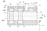
- FIG. 8 is a cross-sectional view taken along the line VIII-VIII in FIG. 7.
- FIG. 9 is an enlarged view of part A in FIG. 8.
- the insulating layer is omitted, and the external electrodes are drawn with two-dot chain lines.
- the element body 10 is drawn transparently so that the structure can be easily understood.
- the second embodiment differs from the first embodiment mainly in the position of the coil axis, the direction of the through-wiring, the material of the element body, the provision of an insulator, and the configuration of the external electrodes, and these different configurations will be described below.
- the other configurations are the same as those of the first embodiment, and their description will be omitted.
- the axis AX of the coil 110 is perpendicular to the X direction. Specifically, the axis AX is parallel to the Y direction and passes through the center of the element body 10 in the X direction. This can reduce the interference with the magnetic flux of the coil 110 by the first external electrode 121 and the second external electrode 122, improving the efficiency of obtaining inductance.
- the length of coil 110 in the axial direction AX is shorter than the inner diameter of coil 110. This allows the coil length to be short and the coil inner diameter to be large, improving the Q value.
- the inner diameter of the coil refers to the equivalent diameter of a circle based on the minimum area of the region surrounded by coil 110 when viewed through the axial direction AX.
- the element body 10 is an inorganic insulator.
- the material of the element body 10 is preferably glass, which has high insulating properties and can suppress eddy currents and increase the Q value.
- the element body 10 preferably contains silicon, which provides high thermal stability of the element body 10 and therefore can suppress fluctuations in dimensions of the element body 10 due to heat and reduce variations in electrical characteristics.
- the element body 10 is preferably a single-layer glass plate. This ensures the strength of the element body 10. Furthermore, in the case of a single-layer glass plate, the dielectric loss is small, so the Q value at high frequencies can be increased. Furthermore, since there is no sintering process as in the case of sintered bodies, deformation of the element body 10 during sintering can be suppressed, which suppresses pattern misalignment, making it possible to provide an inductor component with a small inductance tolerance.
- the material of the single-layer glass plate is preferably a photosensitive glass plate such as Foturan II (registered trademark of Schott AG).
- the single-layer glass plate preferably contains cerium oxide (ceria: CeO 2 ), in which case the cerium oxide acts as a sensitizer, making processing by photolithography easier.
- the single-layer glass plate can be processed by mechanical processing such as drilling and sandblasting, dry/wet etching using a photoresist/metal mask, laser processing, etc., it may be a glass plate that does not have photosensitivity.
- the single-layer glass plate may be made by sintering a glass paste, or may be formed by a known method such as the float method.
- the bottom wiring 11b extends in only one direction. Specifically, the bottom wiring 11b extends in the X direction.
- the multiple bottom wirings 11b are arranged in parallel along the Y direction.
- the multiple bottom wirings 11b include the endmost coil wiring 11e located on one side of the axis AX direction (Y direction). In this embodiment, among the multiple bottom wirings 11b, each of the two bottom wirings 11b located at both ends in the axis AX direction is the endmost coil wiring 11e.
- the top wiring 11t extends in only one direction. Specifically, the top wiring 11t extends in the X direction with a slight inclination toward the Y direction.
- the multiple top wirings 11t are arranged in parallel along the Y direction.
- the first through wiring 13 is disposed on the first end face 100e1 side with respect to the axis AX within the through hole V of the element body 10
- the second through wiring 14 is disposed on the second end face 100e2 side with respect to the axis AX within the through hole V of the element body 10.
- the first through wiring 13 and the second through wiring 14 each extend in a direction perpendicular to the bottom surface 100b and the top surface 100t.
- the multiple first through wirings 13 and the multiple second through wirings 14 are each disposed in parallel along the Y direction.
- the inductor component 1F has an insulator 22.
- the insulator 22 covers both the bottom surface 100b and the top surface 100t of the element body 10. Note that the insulator 22 may be provided only on the bottom surface 100b out of the bottom surface 100b and the top surface 1100t.
- the insulator 22 is a member that covers the wiring (bottom wiring 11b, top wiring 11t) to protect the wiring from external forces, prevent damage to the wiring, and improve the insulation of the wiring.
- the insulator 22 is preferably an organic insulator.
- the insulator 22 may be a resin film such as epoxy or polyimide, which is easy to form.
- the insulator 22 is preferably made of a material with a low dielectric constant, which can reduce the stray capacitance formed between the coil 110 and the external electrodes 121 and 122 when the insulator 22 is present between the coil 110 and the external electrodes 121 and 122.
- the insulator 22 can be formed, for example, by laminating a resin film such as ABF GX-92 (manufactured by Ajinomoto Fine-Techno Co., Ltd.), or by applying a paste-like resin and thermally curing it.
- the insulator 22 may be an inorganic film such as an oxide, nitride, or oxynitride of silicon or hafnium, which has excellent insulation properties and thin film forming properties.
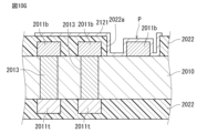
- the insulator 22 covering the bottom surface 100b has an opening 22a so that the connection portion of the endmost coil wiring 11e that is connected to the external electrodes 121, 122 is exposed.
- the opening 22a is a through hole that penetrates the insulator 22 in the thickness direction (Z direction).
- the shape of the opening 22a when viewed from the Z direction is not particularly limited as long as it exposes the above-mentioned connection portion of the bottom wiring 11b. In this embodiment, as shown in FIG. 7, the shape of the opening 22a when viewed from the Z direction is sufficiently larger than the shape of the above-mentioned connection portion of the bottom wiring 11b, and is similar to the shape of the above-mentioned connection portion.
- the shape of the connection portion of the endmost coil wiring 11e located on the second side surface 100s2 side with respect to the center of the element body 10 that connects to the first external electrode 121 is bullet-shaped with a tip that narrows in width in the Y direction as it approaches the reverse X direction.
- the shape of the opening 22a provided on the first external electrode 121 side is sufficiently larger than the shape of the connection portion, and is bullet-shaped with a tip that narrows in width in the Y direction as it approaches the reverse X direction so as to be similar to the shape of the connection portion.
- the shape of the connection portion connected to the second external electrode 122 is bullet-shaped with a tip whose width in the Y direction narrows toward the forward X direction side when viewed from the Z direction.
- the shape of the opening 22a provided on the second external electrode 122 side when viewed from the Z direction is sufficiently larger than the shape of the connection portion, and is bullet-shaped with a tip whose width in the Y direction narrows toward the forward X direction side so as to be similar to the shape of the connection portion.
- connection portion By making the shape of the opening 22a sufficiently larger than the shape of the connection portion, the connection portion is more reliably exposed from the insulator 22, and by making the shape of the opening 22a similar to the shape of the connection portion, the amount of etching of the insulator 22 can be minimized to ensure the insulation of the wiring.
- the first external electrode 121 is provided so as to cover the entire opening 22a located on the first end face 100e1 side when viewed from the Z direction.
- the first external electrode 121 includes a first portion P1 in contact with at least a part of the first side face S1 of the endmost coil wiring 11e, a second portion P2 in contact with at least a part of the upper face u of the endmost coil wiring 11e, and a third portion P3 in contact with at least a part of the second side face s2 of the endmost coil wiring 11e, and the first portion P1, the second portion P2, and the third portion P3 are successively arranged in this order to form a protrusion P protruding in the first direction D1.
- the first external electrode 121 is in contact with the entire surface of the first side surface S1 of the endmost coil wiring 11e that is exposed from the insulator 22, is in contact with the entire surface of the top surface u of the endmost coil wiring 11e that is exposed from the element body 10, and is in contact with the entire surface of the second side surface S2 of the endmost coil wiring 11e that is exposed from the element body 10.
- the first external electrode 121 has a protrusion P at a position corresponding to the portion of the endmost coil wiring 11e that is exposed from the element body 10.
- the second external electrode 122 is provided so as to cover the entire opening 22a located on the second end surface 100e2 side when viewed from the Z direction.
- the second external electrode 122 includes a first portion that contacts at least a part of the first side surface S1 of the endmost coil wiring 11e, a second portion that contacts at least a part of the upper surface u of the endmost coil wiring 11e, and a third portion that contacts at least a part of the second side surface s2 of the endmost coil wiring 11e, and the first portion, the second portion, and the third portion form a convex portion P that protrudes in the first direction D1 side in this order.
- the second external electrode 122 contacts the entire surface of the first side surface S1 of the endmost coil wiring 11e that is exposed from the insulator 22, contacts the entire surface of the upper surface u of the endmost coil wiring 11e that is exposed from the element body 10, and contacts the entire surface of the second side surface S2 of the endmost coil wiring 11e that is exposed from the element body 10.
- the second external electrode 122 has a protrusion P at a position corresponding to the exposed portion of the endmost coil wiring 11e from the element body 10.
- the first external electrode 121 and the second external electrode 122 are located inside the outer surface 100 of the element body 10.
- the first external electrode 121 and the second external electrode 122 are not in contact with the outer surface 100 of the element body 10, so that when singulating into individual inductor components 1F, the load on the first external electrode 121 and the second external electrode 122 can be reduced, and deformation and peeling of the first external electrode 121 and the second external electrode 122 can be suppressed. Therefore, even if the inductor component 1F is made small, deformation and peeling of the first external electrode 121 and the second external electrode 122 can be prevented.
- the first external electrode 121 and the second external electrode 122 have a protrusion P protruding in the first direction D1, so that the surface area is increased compared to when the electrodes are flat without the protrusion P, and the strength of adhesion to a connecting member such as solder can be improved.
- the protrusion P of the first external electrode 121 and the second external electrode 122 is in contact with the endmost coil wiring 11e, so that the first external electrode 121 and the second external electrode 122 can be directly connected to the endmost coil wiring 11e. This makes it possible to reduce the DC resistance (Rdc) compared to when the first external electrode 121 and the second external electrode 122 are connected to the endmost coil wiring 11e using, for example, via wiring.
- the electrode further includes an insulator 22 provided on a portion of the bottom surface 100b, and at least a portion of the first external electrode 121 is in continuous contact with the insulator 22, the bottom surface 100b, and the first side surface S1 of the protrusion P.
- the first external electrode 121 includes a bottom portion BP1 that is provided continuously from the first portion P1 of the protrusion P on the side opposite to the second portion P2 and extends in a direction parallel to the bottom surface 100b, and a wall portion WP1 that is provided continuously from the bottom portion BP1 and extends in the first direction D1.
- the wall portion WP1, the bottom portion BP1, and the first portion P1 are in continuous contact with the insulator 22, the bottom surface 100b, and the first side surface S1 of the protrusion P.
- the first external electrode 121 is in continuous contact with the insulator 22, the bottom surface 100b, and the second side surface S2 of the convex portion P.
- the first external electrode 121 includes a bottom portion BP2 that is provided continuously from the third portion P3 of the convex portion P on the side opposite the second portion P2 and extends in a direction parallel to the bottom surface 100b, and a wall portion WP2 that is provided continuously from the bottom portion BP2 and extends in the first direction D1.
- the wall portion WP2, the bottom portion BP2, and the third portion P3 are in continuous contact with the insulator 22, the bottom surface 100b, and the second side surface S2 of the convex portion P.
- the first external electrode 121 is in continuous contact with the insulator 22, the bottom surface 100b, and the first side surface S1 of the protrusion P, so that an uneven shape can be imparted to the first external electrode 121.
- This can further improve the adhesive strength with a connecting member such as solder.
- at least a portion of the first external electrode 121 is in continuous contact with the insulator 22, the bottom surface 100b, and the second side surface S2 of the protrusion P, so that an uneven shape can be imparted to the first external electrode 121.
- This can further improve the adhesive strength with a connecting member such as solder.
- the second external electrode 122 may be in continuous contact with the insulator 22, the bottom surface 100b, and the first side surface S1 of the protrusion P.
- the first external electrode 121 further includes a fourth portion P4 that is spaced apart from the second portion P2 and is located closer to the first direction D1 than the second portion P2.
- the fourth portion P4 is a portion of the first external electrode 121 that is provided on the upper surface 22u of the insulator 22. With this configuration, since the fourth portion P4 is further included, the surface area of the first external electrode 121 can be further increased.
- the second external electrode 122 may also further include a fourth portion that is spaced apart from the second portion and is located closer to the first direction D1 than the second portion.
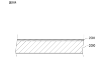
- copper foil 2001 is provided by printing on a base substrate 2000.
- the material of the base substrate 2000 is the same as that of the base substrate 1000 in the first embodiment.
- a glass substrate 2010 that will become the element body 10 is provided on a base substrate 2000.
- the base substrate 2000 and the glass substrate 2010 are attached to each other using a jig such as conductive tape, pins, or a frame.
- the glass substrate 2010 has a through hole V.
- the glass substrate 2010 is, for example, a TGV (Through Glass Via) substrate.
- a TGV substrate is a substrate in which a through hole has been formed in advance by a laser, photolithography, or the like.
- the glass substrate 2010 may be, for example, a TSV (Through Silicon Via) substrate, or may be something else.
- Ti/Cu or other necessary conductive materials may be deposited in advance as a seed on the surface of the glass substrate 2010 by sputtering or the like.
- a first through conductor layer 2013 that will become the first through wiring 13 is formed in the through hole V of the glass substrate 2010.
- a second through conductor layer that will become the second through wiring 14 is similarly formed in the through hole V.
- electrolytic plating is performed in the through hole V of the glass substrate 2010 to form the first through conductor layer 2013.
- a seed layer may be formed on the surface of the glass substrate 2010 or the inner surface of the through hole V by sputtering or the like, and a through conductor layer may be formed by known methods such as filled plating, conformal plating, or a printing and filling method of a conductive paste. If there is unnecessary plating growth on the surface of the glass substrate 2010, the unnecessary portions are removed by polishing, CMP, wet etching (etch-back), or dry etching.
- the base substrate 2000 is peeled off from the glass substrate 2010.
- the base substrate 2000 may be removed mechanically by grinding or the like, or may be removed chemically by etching or the like.
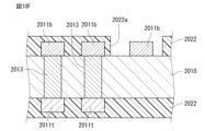
- a bottom conductor layer 2011b that will become the bottom wiring 11b and a top conductor layer 2011t that will become the top wiring 11t are formed on a glass substrate 2010.
- a seed layer (not shown) is provided on the entire surface of the glass substrate 2010, and a patterned photoresist is formed on the seed layer.
- a copper layer is formed by electrolytic plating on the seed layer in the openings of the photoresist.
- the photoresist and seed layer are removed by wet etching or dry etching. This forms the bottom conductor layer 2011b and the top conductor layer 2011t that are patterned into an arbitrary shape.
- the bottom conductor layer 2011b and the top conductor layer 2011t may be formed one at a time, or both may be formed simultaneously.
- insulating layers 2022 that become insulators 22 are provided on the top and bottom surfaces of glass substrate 2010 so as to cover the conductor layers.
- the bottom-side insulating layer 2022 and the top-side insulating layer 2022 may be formed one at a time, or both may be formed simultaneously.
- holes 2022a are provided on bottom conductor layer 2011b of bottom-side insulating layer 2022 using photolithography or laser processing.
- the portions of bottom conductor layer 2011b that will become connection portions to be connected to the first and second external electrodes are exposed from insulating layer 2022. Holes 2022a become openings 22a.
- the first external electrode conductor layer 2121 which will become the first external electrode 121, is provided on the bottom-side insulating layer 2022.
- the first external electrode conductor layer 2121 is connected to the bottom-side conductor layer 2011b through the hole 2022a.
- the first external electrode conductor layer 2121 also contacts the bottom-side conductor layer 2011b through the hole 2022a, forming a convex portion P.
- a Pd catalyst (not shown) is provided on the bottom-side insulating layer 2022, and a Ni, Au plating layer is formed by electroless plating.
- a patterned photoresist is formed on the plating layer.
- the plating layer in the opening of the photoresist is removed by wet etching or dry etching. This forms the first external electrode conductor layer 2121 patterned into an arbitrary shape.
- a seed layer (not shown) is provided on the bottom-side insulating layer 2022, and a patterned photoresist is formed on the seed layer.
- the seed layer in the opening of the photoresist is removed by wet etching or dry etching.
- a Ni or Au plating layer may be formed on the remaining seed layer by electroless plating.
- a second external electrode conductor layer that will become the second external electrode 122 is similarly provided on the insulating layer 2022 on the bottom side.
- the chip is cut into individual pieces along cut lines D. This produces inductor component 1F as shown in FIG. 8.
- Fig. 11A is a view showing a first modified example of an inductor component, corresponding to the VIII-VIII cross section of Fig. 7.
- the first through wiring 13 extends in a direction perpendicular to the bottom wiring 11b, and the cross-sectional area of each of both end portions 13e in the extending direction of the first through wiring 13 is larger than the cross-sectional area of a central portion 13m in the extending direction of the first through wiring 13. That is, in a cross section along the extending direction of the first through wiring 13, the width in the direction perpendicular to the extending direction of the first through wiring 13 increases continuously from the central portion 13m toward both end portions 13e.
- the cross-sectional area of one end 13e of the first through-hole wiring 13 may be larger than the cross-sectional area of the central portion 13m of the first through-hole wiring 13.
- the cross-sectional area of at least one end of the second through-hole wiring 14 may be larger than the cross-sectional area of the central portion 13m of the first through-hole wiring 13.
- the bottom wiring 11b is provided on the bottom surface 100b, and further includes an insulator 22 that covers the bottom wiring 11b and has a shape that conforms to the shape of the bottom wiring 11b, and at least a portion of the first external electrode 121 contacts the insulator 22 and is shaped to conform to the shape of the bottom wiring 11b.
- the insulator 22 covers the bottom wiring 11b, and has a shape that extends in the X direction when viewed from the Z direction, and is shaped to conform to the shape of the bottom wiring 11b.
- the insulator 22 is provided so as to cover each of the bottom wirings 11b separately.
- the first external electrode 121 excluding the protrusion P and the portion in contact with the bottom surface 100b, is in contact with the insulator 22 and has a shape that extends in the X direction when viewed from the Z direction, and is shaped to match the shape of the bottom surface wiring 11b.
- the insulators 22 also cover the top wiring 11t, and when viewed from the Z direction, are shaped to extend in the X direction at a slight incline toward the Y direction, and are shaped to match the shape of the top wiring 11t. In short, the insulators 22 are provided so as to cover each of the top wirings 11t separately. This allows the material cost of the insulators 22 to be reduced.
- Examples of a method for forming the insulator 22 having a shape that conforms to the shape of the bottom wiring 11b or the top wiring 11t include a method of forming an organic resin or an inorganic insulator on the surface of the bottom wiring 11b or the top wiring 11t using a method such as CVD (Chemical Vapor Deposition), sputtering, or coating.
- CVD Chemical Vapor Deposition
- sputtering or coating.
- the first external electrode 121 is shaped to conform to the shape of the bottom wiring 11b, which further increases the surface area of the first external electrode 121 and further improves the bonding strength with a connecting member such as solder.
- the second external electrode 122 may be in contact with the insulator 22 and may be shaped to match the shape of the bottom wiring 11b.
- FIG. 11B is a diagram corresponding to the VIII-VIII cross section of FIG. 7 showing the second modified inductor component.
- an insulator 22 is further provided on the entire surface of the bottom surface 100b except for the portion where the bottom surface wiring 11b is provided and the outer periphery portion. The thickness of the insulator 22 in the Z direction is thinner than the thickness of the bottom surface wiring 11b in the Z direction.
- the area of the portion of the first external electrode 121 facing the bottom surface wiring 11b is smaller than that of the first modified example, so that the stray capacitance that may occur between the first external electrode 121 and the bottom surface wiring 11b can be reduced more than that of the first modified example.
- the insulator 22 is filled between the adjacent bottom surface wirings 11b more than that of the first modified example, the insulation between the adjacent bottom surface wirings 11b can be ensured more than that of the first modified example.
- the organic insulator is located inside the outer surface 100 of the inorganic insulator when viewed from a direction perpendicular to the bottom surface 100b.
- the organic insulator is easily given fluidity, and when the wiring (bottom surface wiring 11b, top surface wiring 11t) is covered with the organic insulator, the organic insulator can be easily filled between adjacent wirings, improving insulation.
- the organic insulator is not in contact with the outer surface of the inorganic insulator, the load on the organic insulator can be reduced when singulating into individual inductor components 1H, and deformation and peeling of the organic insulator can be suppressed.
- an insulator 22 is further provided on the entire area of the top surface 100t excluding the portion where the top surface wiring 11t is provided and the outer periphery.
- the thickness of the insulator 22 in the Z direction is thinner than the thickness of the top surface wiring 11t in the Z direction. This makes it possible to protect the element body 10 from the external environment.
- FIG. 11C is a schematic cross-sectional view of the first through wiring showing a third modified example of the inductor component.
- the first through wiring 13 has a conductive layer 13s located on the outer periphery side as viewed from the extending direction of the first through wiring 13, and a non-conductive layer 13u located inside the conductive layer 13s.
- current mainly flows through the surface of the first through wiring 13 due to the skin effect, so that the Q value is not lowered by providing the conductive layer 13s on the outer periphery side.
- the non-conductive layer 13u on the inside stress can be alleviated, and manufacturing costs can be reduced by not using a conductor.
- a seed layer is provided on the inner surface of the through hole V of the element body 10 by sputtering or electroless plating. Then, a plating layer is formed on the seed layer by electrolytic plating. In this way, multiple conductive layers 13s such as Ti/Cu/electrolytic Cu or Pd/electroless Cu/electrolytic Cu can be formed on the outer periphery of the first through wiring 13. After that, the inside of the conductive layer 13s is sealed with resin by printing or heat pressing to form a non-conductive layer 13u made of resin. In this way, stress can be relieved by the non-conductive layer 13u inside the first through wiring 13 while current flows on the surface (conductive layer 13s) of the first through wiring 13.
- the second through-hole wiring 14 may have a conductive layer located on the outer periphery when viewed from the direction in which the second through-hole wiring 14 extends, and a non-conductive layer located inside the conductive layer.
- both the first external electrode and the second external electrode have a convex portion, but only one of the first external electrode and the second external electrode may have a convex portion.
- the external electrode that does not have a convex portion may be connected to the bottom wiring, for example, via a via wiring provided in the element body.
- the present disclosure includes the following aspects. ⁇ 1> an element body including a first main surface and a second main surface opposed to each other; a coil, at least a portion of which is provided inside the element body and which is wound helically along an axis; a first external electrode and a second external electrode provided outside the element body and electrically connected to the coil; Equipped with The axis of the coil is disposed parallel to the first major surface;
- the coil is a plurality of first coil wirings provided on the first main surface side with respect to the axis and arranged along the axis on a plane parallel to the first main surface; a plurality of second coil wirings provided on the second main surface side with respect to the axis and arranged along the axis on a plane parallel to the second main surface; a plurality of first through wires extending from the first coil wiring toward the second coil wiring and arranged along the axis; a plurality of second through wirings extending from the first coil wiring toward the second coil wiring, provided on an opposite side of
- ⁇ 2> The inductor component according to ⁇ 1>, wherein a thickness of the first external electrode is thinner than a thickness of the first coil wiring.
- ⁇ 3> The inductor component according to ⁇ 1> or ⁇ 2>, wherein the element body contains SiO 2 .
- ⁇ 4> The inductor component according to any one of ⁇ 1> to ⁇ 3>, wherein the first external electrode is composed of a plurality of conductive layers, including a conductive layer made of a different material from the conductive layer constituting the endmost coil wiring.
- ⁇ 5> The inductor component according to any one of ⁇ 1> to ⁇ 4>, wherein the first external electrode further includes a bottom portion that is provided continuously from the first portion of the convex portion to the opposite side to the second portion and extends in a direction parallel to the first main surface, and a wall portion that is provided continuously from the bottom portion and extends in the first direction.
- the first external electrode further includes a fourth portion separated from the second portion and located on the first direction side of the second portion.
- the first main surface has a recess, The recess has a stepped side surface,
- ⁇ 8> Further comprising an insulator provided on a portion of the first main surface, An inductor component described in any one of ⁇ 1> to ⁇ 7>, wherein at least a portion of the first external electrode is in continuous contact with the insulator, the first main surface, and the first side surface of the convex portion.
- the first coil wiring is provided on the first main surface, The coil wiring is covered with an insulator having a shape conforming to the shape of the first coil wiring.
- ⁇ 10> Further comprising an organic insulator provided on the first main surface, An inductor component described in any one of ⁇ 1> to ⁇ 9>, wherein the base body is an inorganic insulator, and the organic insulator is located inside the outer surface of the inorganic insulator when viewed in a direction perpendicular to the first main surface.
- ⁇ 11> The inductor component according to any one of ⁇ 1> to ⁇ 10>, wherein the first through wiring and the second through wiring are not parallel to each other when viewed in a direction parallel to the axis.
- the body includes SiO2 , The inductor component according to any one of ⁇ 1> to ⁇ 11>, wherein the first through wiring contains SiO 2 .
- ⁇ 13> The inductor component according to any one of ⁇ 1> to ⁇ 12>, wherein the first through wiring includes a void portion or a resin portion.
- ⁇ 14> An inductor component described in any one of ⁇ 1> to ⁇ 13>, wherein the first through wiring has a conductive layer located on the outer periphery when viewed from the direction in which the first through wiring extends, and a non-conductive layer located inside the conductive layer.
- ⁇ 15> The inductor component according to any one of ⁇ 1> to ⁇ 14>, wherein an axial length of the coil is shorter than an inner diameter of the coil.
- the first through-hole wiring extends in a direction perpendicular to the first main surface
- ⁇ 18> An inductor component according to any one of ⁇ 1> to ⁇ 17>, wherein, when viewed in a direction perpendicular to the first main surface, the first external electrode and the second external electrode are located inside an outer surface of the element body.
Landscapes
- Engineering & Computer Science (AREA)
- Power Engineering (AREA)
- Microelectronics & Electronic Packaging (AREA)
- Coils Or Transformers For Communication (AREA)
Priority Applications (3)
| Application Number | Priority Date | Filing Date | Title |
|---|---|---|---|
| CN202380076159.9A CN120129946A (zh) | 2022-11-02 | 2023-08-23 | 电感器部件 |
| JP2024554273A JP7687538B2 (ja) | 2022-11-02 | 2023-08-23 | インダクタ部品 |
| US19/195,362 US20250259783A1 (en) | 2022-11-02 | 2025-04-30 | Inductor component |
Applications Claiming Priority (2)
| Application Number | Priority Date | Filing Date | Title |
|---|---|---|---|
| JP2022-176445 | 2022-11-02 | ||
| JP2022176445 | 2022-11-02 |
Related Child Applications (1)
| Application Number | Title | Priority Date | Filing Date |
|---|---|---|---|
| US19/195,362 Continuation US20250259783A1 (en) | 2022-11-02 | 2025-04-30 | Inductor component |
Publications (1)
| Publication Number | Publication Date |
|---|---|
| WO2024095570A1 true WO2024095570A1 (ja) | 2024-05-10 |
Family
ID=90930153
Family Applications (1)
| Application Number | Title | Priority Date | Filing Date |
|---|---|---|---|
| PCT/JP2023/030260 Ceased WO2024095570A1 (ja) | 2022-11-02 | 2023-08-23 | インダクタ部品 |
Country Status (4)
| Country | Link |
|---|---|
| US (1) | US20250259783A1 (https=) |
| JP (1) | JP7687538B2 (https=) |
| CN (1) | CN120129946A (https=) |
| WO (1) | WO2024095570A1 (https=) |
Citations (5)
| Publication number | Priority date | Publication date | Assignee | Title |
|---|---|---|---|---|
| JP2003218525A (ja) * | 2002-01-18 | 2003-07-31 | Fujitsu Ltd | 回路基板及びその製造方法 |
| JP2007027649A (ja) * | 2005-07-21 | 2007-02-01 | Murata Mfg Co Ltd | 積層コイル部品及びその製造方法 |
| JP2008066592A (ja) * | 2006-09-08 | 2008-03-21 | Fuji Electric Holdings Co Ltd | 薄型磁気部品の製造方法 |
| JP2011096998A (ja) * | 2009-10-30 | 2011-05-12 | Samsung Electro-Mechanics Co Ltd | 凹凸パターン付きビアパッドを含む印刷回路基板及びその製造方法 |
| WO2017212990A1 (ja) * | 2016-06-07 | 2017-12-14 | 株式会社村田製作所 | 電子部品、振動板、電子機器および電子部品の製造方法 |
-
2023
- 2023-08-23 CN CN202380076159.9A patent/CN120129946A/zh active Pending
- 2023-08-23 WO PCT/JP2023/030260 patent/WO2024095570A1/ja not_active Ceased
- 2023-08-23 JP JP2024554273A patent/JP7687538B2/ja active Active
-
2025
- 2025-04-30 US US19/195,362 patent/US20250259783A1/en active Pending
Patent Citations (5)
| Publication number | Priority date | Publication date | Assignee | Title |
|---|---|---|---|---|
| JP2003218525A (ja) * | 2002-01-18 | 2003-07-31 | Fujitsu Ltd | 回路基板及びその製造方法 |
| JP2007027649A (ja) * | 2005-07-21 | 2007-02-01 | Murata Mfg Co Ltd | 積層コイル部品及びその製造方法 |
| JP2008066592A (ja) * | 2006-09-08 | 2008-03-21 | Fuji Electric Holdings Co Ltd | 薄型磁気部品の製造方法 |
| JP2011096998A (ja) * | 2009-10-30 | 2011-05-12 | Samsung Electro-Mechanics Co Ltd | 凹凸パターン付きビアパッドを含む印刷回路基板及びその製造方法 |
| WO2017212990A1 (ja) * | 2016-06-07 | 2017-12-14 | 株式会社村田製作所 | 電子部品、振動板、電子機器および電子部品の製造方法 |
Also Published As
| Publication number | Publication date |
|---|---|
| JP7687538B2 (ja) | 2025-06-03 |
| US20250259783A1 (en) | 2025-08-14 |
| JPWO2024095570A1 (https=) | 2024-05-10 |
| CN120129946A (zh) | 2025-06-10 |
Similar Documents
| Publication | Publication Date | Title |
|---|---|---|
| JP2024019217A (ja) | パッケージ基板およびそれを備えた半導体複合装置 | |
| CN115621014B (zh) | 电感器部件以及电感器部件的安装构造 | |
| JP5173758B2 (ja) | 半導体パッケージの製造方法 | |
| JP7722537B2 (ja) | インダクタ部品 | |
| JP7652283B2 (ja) | インダクタ部品 | |
| CN115732192A (zh) | 电感器部件以及电感器部件的安装构造 | |
| JP7677238B2 (ja) | 受動部品、三次元デバイスおよび受動部品の製造方法 | |
| JP7687538B2 (ja) | インダクタ部品 | |
| JP7816559B2 (ja) | インダクタ部品 | |
| WO2024095565A1 (ja) | インダクタ部品 | |
| WO2024095569A1 (ja) | インダクタ部品 | |
| WO2024095566A1 (ja) | インダクタ部品 | |
| WO2024095571A1 (ja) | インダクタ部品 | |
| JP7533368B2 (ja) | インダクタ部品 | |
| US10629364B2 (en) | Inductor and method for manufacturing the same | |
| JP2026071306A (ja) | インダクタ部品 | |
| US20220392699A1 (en) | Inductor component | |
| JP5524681B2 (ja) | 配線基板内蔵用コンデンサ、及び配線基板 | |
| JP2011216790A (ja) | 配線基板内蔵用コンデンサ及び配線基板 |
Legal Events
| Date | Code | Title | Description |
|---|---|---|---|
| 121 | Ep: the epo has been informed by wipo that ep was designated in this application |
Ref document number: 23885340 Country of ref document: EP Kind code of ref document: A1 |
|
| WWE | Wipo information: entry into national phase |
Ref document number: 2024554273 Country of ref document: JP |
|
| WWE | Wipo information: entry into national phase |
Ref document number: 202380076159.9 Country of ref document: CN |
|
| NENP | Non-entry into the national phase |
Ref country code: DE |
|
| WWP | Wipo information: published in national office |
Ref document number: 202380076159.9 Country of ref document: CN |
|
| 122 | Ep: pct application non-entry in european phase |
Ref document number: 23885340 Country of ref document: EP Kind code of ref document: A1 |