WO2024090449A1 - 金属am銅合金粉末および積層造形物の製造方法 - Google Patents
金属am銅合金粉末および積層造形物の製造方法 Download PDFInfo
- Publication number
- WO2024090449A1 WO2024090449A1 PCT/JP2023/038396 JP2023038396W WO2024090449A1 WO 2024090449 A1 WO2024090449 A1 WO 2024090449A1 JP 2023038396 W JP2023038396 W JP 2023038396W WO 2024090449 A1 WO2024090449 A1 WO 2024090449A1
- Authority
- WO
- WIPO (PCT)
- Prior art keywords
- copper alloy
- metal
- alloy powder
- powder
- copper
- Prior art date
- Legal status (The legal status is an assumption and is not a legal conclusion. Google has not performed a legal analysis and makes no representation as to the accuracy of the status listed.)
- Ceased
Links
Images




Classifications
-
- B—PERFORMING OPERATIONS; TRANSPORTING
- B22—CASTING; POWDER METALLURGY
- B22D—CASTING OF METALS; CASTING OF OTHER SUBSTANCES BY THE SAME PROCESSES OR DEVICES
- B22D11/00—Continuous casting of metals, i.e. casting in indefinite lengths
-
- B—PERFORMING OPERATIONS; TRANSPORTING
- B22—CASTING; POWDER METALLURGY
- B22F—WORKING METALLIC POWDER; MANUFACTURE OF ARTICLES FROM METALLIC POWDER; MAKING METALLIC POWDER; APPARATUS OR DEVICES SPECIALLY ADAPTED FOR METALLIC POWDER
- B22F1/00—Metallic powder; Treatment of metallic powder, e.g. to facilitate working or to improve properties
-
- B—PERFORMING OPERATIONS; TRANSPORTING
- B22—CASTING; POWDER METALLURGY
- B22F—WORKING METALLIC POWDER; MANUFACTURE OF ARTICLES FROM METALLIC POWDER; MAKING METALLIC POWDER; APPARATUS OR DEVICES SPECIALLY ADAPTED FOR METALLIC POWDER
- B22F1/00—Metallic powder; Treatment of metallic powder, e.g. to facilitate working or to improve properties
- B22F1/05—Metallic powder characterised by the size or surface area of the particles
- B22F1/052—Metallic powder characterised by the size or surface area of the particles characterised by a mixture of particles of different sizes or by the particle size distribution
-
- B—PERFORMING OPERATIONS; TRANSPORTING
- B22—CASTING; POWDER METALLURGY
- B22F—WORKING METALLIC POWDER; MANUFACTURE OF ARTICLES FROM METALLIC POWDER; MAKING METALLIC POWDER; APPARATUS OR DEVICES SPECIALLY ADAPTED FOR METALLIC POWDER
- B22F1/00—Metallic powder; Treatment of metallic powder, e.g. to facilitate working or to improve properties
- B22F1/16—Metallic particles coated with a non-metal
-
- B—PERFORMING OPERATIONS; TRANSPORTING
- B22—CASTING; POWDER METALLURGY
- B22F—WORKING METALLIC POWDER; MANUFACTURE OF ARTICLES FROM METALLIC POWDER; MAKING METALLIC POWDER; APPARATUS OR DEVICES SPECIALLY ADAPTED FOR METALLIC POWDER
- B22F10/00—Additive manufacturing of workpieces or articles from metallic powder
- B22F10/20—Direct sintering or melting
- B22F10/28—Powder bed fusion, e.g. selective laser melting [SLM] or electron beam melting [EBM]
-
- B—PERFORMING OPERATIONS; TRANSPORTING
- B22—CASTING; POWDER METALLURGY
- B22F—WORKING METALLIC POWDER; MANUFACTURE OF ARTICLES FROM METALLIC POWDER; MAKING METALLIC POWDER; APPARATUS OR DEVICES SPECIALLY ADAPTED FOR METALLIC POWDER
- B22F10/00—Additive manufacturing of workpieces or articles from metallic powder
- B22F10/30—Process control
- B22F10/34—Process control of powder characteristics, e.g. density, oxidation or flowability
-
- B—PERFORMING OPERATIONS; TRANSPORTING
- B22—CASTING; POWDER METALLURGY
- B22F—WORKING METALLIC POWDER; MANUFACTURE OF ARTICLES FROM METALLIC POWDER; MAKING METALLIC POWDER; APPARATUS OR DEVICES SPECIALLY ADAPTED FOR METALLIC POWDER
- B22F10/00—Additive manufacturing of workpieces or articles from metallic powder
- B22F10/60—Treatment of workpieces or articles after build-up
- B22F10/64—Treatment of workpieces or articles after build-up by thermal means
-
- B—PERFORMING OPERATIONS; TRANSPORTING
- B22—CASTING; POWDER METALLURGY
- B22F—WORKING METALLIC POWDER; MANUFACTURE OF ARTICLES FROM METALLIC POWDER; MAKING METALLIC POWDER; APPARATUS OR DEVICES SPECIALLY ADAPTED FOR METALLIC POWDER
- B22F3/00—Manufacture of workpieces or articles from metallic powder characterised by the manner of compacting or sintering; Apparatus specially adapted therefor ; Presses and furnaces
- B22F3/24—After-treatment of workpieces or articles
-
- B—PERFORMING OPERATIONS; TRANSPORTING
- B22—CASTING; POWDER METALLURGY
- B22F—WORKING METALLIC POWDER; MANUFACTURE OF ARTICLES FROM METALLIC POWDER; MAKING METALLIC POWDER; APPARATUS OR DEVICES SPECIALLY ADAPTED FOR METALLIC POWDER
- B22F9/00—Making metallic powder or suspensions thereof
- B22F9/02—Making metallic powder or suspensions thereof using physical processes
- B22F9/06—Making metallic powder or suspensions thereof using physical processes starting from liquid material
- B22F9/08—Making metallic powder or suspensions thereof using physical processes starting from liquid material by casting, e.g. through sieves or in water, by atomising or spraying
-
- B—PERFORMING OPERATIONS; TRANSPORTING
- B33—ADDITIVE MANUFACTURING TECHNOLOGY
- B33Y—ADDITIVE MANUFACTURING, i.e. MANUFACTURING OF THREE-DIMENSIONAL [3D] OBJECTS BY ADDITIVE DEPOSITION, ADDITIVE AGGLOMERATION OR ADDITIVE LAYERING, e.g. BY 3D PRINTING, STEREOLITHOGRAPHY OR SELECTIVE LASER SINTERING
- B33Y10/00—Processes of additive manufacturing
-
- B—PERFORMING OPERATIONS; TRANSPORTING
- B33—ADDITIVE MANUFACTURING TECHNOLOGY
- B33Y—ADDITIVE MANUFACTURING, i.e. MANUFACTURING OF THREE-DIMENSIONAL [3D] OBJECTS BY ADDITIVE DEPOSITION, ADDITIVE AGGLOMERATION OR ADDITIVE LAYERING, e.g. BY 3D PRINTING, STEREOLITHOGRAPHY OR SELECTIVE LASER SINTERING
- B33Y70/00—Materials specially adapted for additive manufacturing
-
- C—CHEMISTRY; METALLURGY
- C22—METALLURGY; FERROUS OR NON-FERROUS ALLOYS; TREATMENT OF ALLOYS OR NON-FERROUS METALS
- C22C—ALLOYS
- C22C1/00—Making non-ferrous alloys
- C22C1/02—Making non-ferrous alloys by melting
-
- C—CHEMISTRY; METALLURGY
- C22—METALLURGY; FERROUS OR NON-FERROUS ALLOYS; TREATMENT OF ALLOYS OR NON-FERROUS METALS
- C22C—ALLOYS
- C22C9/00—Alloys based on copper
- C22C9/06—Alloys based on copper with nickel or cobalt as the next major constituent
-
- Y—GENERAL TAGGING OF NEW TECHNOLOGICAL DEVELOPMENTS; GENERAL TAGGING OF CROSS-SECTIONAL TECHNOLOGIES SPANNING OVER SEVERAL SECTIONS OF THE IPC; TECHNICAL SUBJECTS COVERED BY FORMER USPC CROSS-REFERENCE ART COLLECTIONS [XRACs] AND DIGESTS
- Y02—TECHNOLOGIES OR APPLICATIONS FOR MITIGATION OR ADAPTATION AGAINST CLIMATE CHANGE
- Y02P—CLIMATE CHANGE MITIGATION TECHNOLOGIES IN THE PRODUCTION OR PROCESSING OF GOODS
- Y02P10/00—Technologies related to metal processing
- Y02P10/25—Process efficiency
Definitions
- the present invention relates to a copper alloy powder for metal additive manufacturing (metal AM) that is optimal for metal AM technology, and a method for manufacturing an additively manufactured object.
- metal AM metal additive manufacturing
- metal AM technology which uses powder as the main raw material and creates products using a metal 3D printer, has been put to practical use as a method for manufacturing metal parts with various three-dimensional shapes.
- Major metal AM technologies using metal powder include powder bed fusion (PBF) using electron beams or laser light, and binder jetting.
- Copper alloys have many basic properties suitable for industrial applications, such as electrical conductivity, thermal conductivity, mechanical properties, wear resistance, and heat resistance, and are used as materials for various components.
- attempts have been made to form components of various shapes by metal AM using copper alloy powder in various fields such as space and electrical component applications, and there is an increasing need for copper and copper alloy components manufactured by metal AM.
- Patent Document 1 proposes a technique for producing an additive manufacturing object by metal AM using a copper alloy powder containing either Cr or Si.
- Patent Document 2 proposes a technique for producing an additive manufacturing object by metal AM using a copper alloy powder containing Cr and Zr.
- Metal structures created by metal AM will be used as structural components for a variety of applications; therefore, if voids are present in the additively created body or if the microstructure of the metal material is uneven, this can cause problems in terms of thermomechanical and electrical reliability.
- the most commonly used manufacturing method for metal AM is laser PBF, and attempts are being made to use laser PBF for manufacturing copper and copper alloys as well.
- a thin layer of powder is first formed (powder bed), and then the powder bed is locally irradiated with a laser or an electron beam to melt and solidify the material.
- copper and copper alloys compared with other metal materials such as iron, titanium, and nickel, copper itself has a high reflectance in the visible and infrared ranges, which causes the melting behavior of the copper alloy powder to become unstable during the laser PBF process, and voids are likely to occur inside the manufactured additive manufacturing product, resulting in a number of problems such as unstable quality of the product manufactured by laser PBF and poor productivity, and there is a demand for improvements in the productivity and quality of copper and copper alloys manufactured by laser PBF.
- the most widely used form of raw material for metal AM is powder.
- the electromagnetic wave absorption characteristics of the particles due to coupling and interaction with the electromagnetic waves of the surface layer of each particle constituting the raw material powder affect the melting behavior of the raw material powder, and greatly affect the productivity of parts and the quality including the defect density of the parts.
- the thickness of the powder bed formed in one stacking process is, for example, about several tens of ⁇ m (Non-Patent Document 1), and the raw material powder is melted by irradiating such a relatively thin powder bed with converged electromagnetic waves, and the desired modeling structure is realized by repeating numerous stacking and melting and solidification.
- the electromagnetic wave absorption characteristics of solids have a significant impact on the elementary process of such additive manufacturing using a powder bed. For example, since the electromagnetic wave absorption characteristics of solids are affected by the material composition, improving the uniformity of the powder material composition and microstructure is extremely important for achieving stable quality and high productivity in the entire additive manufacturing product.
- the electromagnetic wave absorption characteristics of copper and copper alloys can be improved, for example, by simply adding a substance with a high absorption rate of the target laser wavelength as a component other than copper.
- the characteristics required for that application can only be realized by appropriately selecting the type and amount of elements added to copper. Therefore, in order to improve the productivity and quality of metal AM objects made of copper or copper alloys, in other words, to improve the laser absorption of raw powders of copper or copper alloys, a simple approach such as adding various foreign elements with high laser absorption rates to copper or copper alloys of optimized composition or increasing the amount of such elements added may deteriorate the performance of copper alloys required for various applications. Therefore, there has been a demand for realizing copper alloy powders for metal AM with improved laser absorption characteristics while maintaining a material composition that can fully ensure the performance of copper alloys required for various applications.
- One important approach to improving the laser absorption properties of powder is to improve the laser absorption ability of each particle by surface modification of each particle that constitutes the powder.
- this surface modification it is possible to apply a coating of a substance that exhibits high absorption rate for the laser wavelength used in metal AM to the surface of each particle of the powder having the desired copper alloy composition.
- a desired coating material may be formed on the particle surface using a wet or gas phase process.
- such a coating process is plagued with problems not only in controlling the thickness of the coating layer on each particle, but also in reproducibility of the coating thickness and homogeneity of the coating material throughout the powder, resulting in a number of issues in the productivity and quality of the molded object.
- one of the factors that can cause structural defects in metal AM objects is the generation of voids due to the entrapment of gases, etc.
- gas is generated due to impurities contained in the copper alloy powder when the powder is melted, and the molten copper alloy or solidified copper alloy can trap the gas components, resulting in the generation of voids inside the additive object produced, which can make it difficult to consistently produce high-quality additive objects.
- the reproducibility of the microstructure of such raw material powders is a similar problem with other metal AM methods such as the binder jet method.
- metal AM of copper alloys improving productivity is a major challenge due to issues with the various raw materials.
- This invention was made in consideration of the above-mentioned circumstances, and aims to provide a copper alloy powder for metal AM that can stably produce high-quality additively molded objects with high reproducibility of the microstructure of objects produced by metal AM and few structural defects such as voids, and a method for producing additively molded objects.
- the copper alloy powder is derived from high-purity copper alloy raw materials, which means that there are fewer impurities that lead to gas components, suppressing the generation of gas during melting. This allows for the realization of dense copper alloy molded bodies with high thermal, electrical, and mechanical properties, and furthermore, it has been discovered that it is possible to manufacture copper alloy powder for metal AM that can achieve high productivity and high quality of copper alloy molded bodies that exhibit such high performance.
- the copper alloy powder for metal AM of aspect 1 of the present invention is a copper alloy powder for metal AM used in metal AM, which is made of a copper alloy containing Si, and is characterized in that a Si-enriched layer is continuously formed on the surface of the copper alloy particles that make up the powder.
- the copper alloy powder for metal AM according to aspect 1 of the present invention is made of a copper alloy containing Si, and a Si-enriched layer is continuously formed on the surface of the copper alloy particles that make up the powder. This makes it possible to stably manufacture high-quality additive manufacturing objects with high reproducibility of the microstructure of the objects produced by metal AM and with few structural defects such as voids.
- the copper alloy powder for metal AM in the copper alloy powder for metal AM according to the first aspect, preferably contains Cr.
- the copper alloy powder for metal AM of aspect 2 of the present invention which is made of a copper alloy containing Cr and Si, and has a Si-enriched layer continuously formed on the surface of the copper alloy particles, it is possible to stably produce high-quality additively molded objects with high reproducibility of the microstructure of the objects produced by metal AM and with few structural defects such as voids.
- the Si-enriched layer preferably contains oxygen.
- the Si-enriched layer formed on the surface of the copper alloy particles contains oxygen, deterioration of the copper alloy powder for metal AM can be suppressed, and the microstructure of the shaped body produced by metal AM can be highly reproducible, making it possible to more stably produce high-quality additively shaped objects with fewer structural defects such as voids.
- the copper alloy in the copper alloy powder for metal AM according to any one of the first to third aspects, preferably contains Cr in the range of 0.1 mass % to 0.8 mass %, Si in the range of 0.4 mass % to 0.8 mass %, Ni in the range of 1.8 mass % to 3.0 mass %, and the remainder is copper and impurities.
- the copper alloy powder for metal AM of aspect 4 of the present invention the copper alloy constituting the copper alloy powder for metal AM has the above-mentioned composition. Therefore, by subjecting an additive manufacturing object produced using this copper alloy powder for metal AM to an appropriate heat treatment, compounds can be precipitated, making it possible to produce an additive manufacturing object having excellent electrical conductivity, thermal conductivity, and strength.
- the volume-based 50% cumulative particle diameter D50 measured by a laser diffraction/scattering method is in the range of 5 ⁇ m or more and 120 ⁇ m or less.
- the 50% cumulative particle diameter D50 on a volume basis measured by a laser diffraction/scattering method is within the range of 5 ⁇ m or more and 120 ⁇ m or less, so that the powder has a particle size distribution suitable for metal AM and enables stable production of additive manufacturing objects.
- a 10% cumulative particle diameter D10 on a volume basis measured by a laser diffraction/scattering method is in the range of 1 ⁇ m or more and 80 ⁇ m or less.
- the volume-based 10% cumulative particle diameter D10 measured by a laser diffraction/scattering method is in the range of 1 ⁇ m or more and 80 ⁇ m or less, so that it has a particle size distribution suitable for metal AM and enables the stable production of additive manufacturing objects.
- the volume-based 90% cumulative particle diameter D90 measured by a laser diffraction/scattering method is in the range of 10 ⁇ m or more and 150 ⁇ m or less.
- the volume-based 90% cumulative particle diameter D90 measured by a laser diffraction/scattering method is in the range of 10 ⁇ m or more and 150 ⁇ m or less, so that it has a particle size distribution suitable for metal AM and enables the stable production of additive manufacturing objects.
- the method for manufacturing an additively molded object according to aspect 8 of the present invention preferably comprises a preparation step of preparing a copper alloy powder for metal AM according to any one of aspects 1 to 7, a first step of forming a powder bed containing the copper alloy powder for metal AM, and a second step of solidifying the copper alloy powder for metal AM at a predetermined position in the powder bed to form a molding bed, and a molding step of producing an additively molded object by sequentially repeating the steps.
- the method for manufacturing an additively molded product according to aspect 8 of the present invention uses a copper alloy powder for metal AM according to any one of aspects 1 to 7, which makes it possible to stably manufacture high-quality additively molded products with high reproducibility of the microstructure of the object produced by additive manufacturing and few structural defects such as voids.
- the method for manufacturing an additively molded object of aspect 9 of the present invention is preferably the method for manufacturing an additively molded object of aspect 8, further comprising a heat treatment step of performing heat treatment at a temperature range of 300°C or higher and lower than the melting point of pure copper after the molding step.
- a heat treatment step of performing heat treatment at a temperature range of 300°C or higher and lower than the melting point of pure copper after the molding step.
- the manufacturing method of an additively molded object of aspect 10 of the present invention is preferably the same as the manufacturing method of an additively molded object of aspect 8, further comprising a first heat treatment step in which heat treatment is performed in a temperature range of 800°C or higher and lower than the melting point of pure copper after the molding step, and a second heat treatment step in which heat treatment is performed in a temperature range of 300°C or higher and lower than 800°C after the first heat treatment.
- the present invention provides a copper alloy powder for metal AM that can stably produce high-quality additively molded objects with high reproducibility of the microstructure of objects produced by metal AM and few structural defects such as voids, and a method for producing additively molded objects.
- FIG. 1 is a schematic explanatory diagram of a copper alloy particle constituting a copper alloy powder for metal AM according to an embodiment.
- FIG. 1 is a flow diagram of a method for producing a copper alloy powder for metal AM according to the present embodiment.
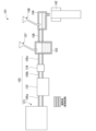
- FIG. 1 is a schematic explanatory diagram of a continuous casting device used when producing the copper alloy powder for metal AM according to the present embodiment.
- FIG. 2 is a flow diagram of a method for producing a layered object according to the present embodiment.
- FIG. 2 is a schematic explanatory diagram of another continuous casting device used in producing the copper alloy powder for metal AM according to the present embodiment.
- FIG. 1 is a diagram showing the results of Auger electron spectroscopy analysis of the outermost surface of a particle constituting the copper alloy powder for metal AM according to the present embodiment, and is a secondary electron image of the particle surface.
- FIG. 2 is a diagram showing the results of Auger electron spectroscopy analysis of the outermost surface of a particle constituting the copper alloy powder for metal AM according to the present embodiment, and is an element mapping image of the particle surface.
- 1 is an example of a graph showing the results of Auger electron spectroscopy analysis of the outermost surface of a particle constituting the copper alloy powder for metal AM according to the present embodiment, and shows an O intensity depth profile.
- 1 is an example of a graph showing the results of Auger electron spectroscopy analysis of the outermost surface of a particle constituting the copper alloy powder for metal AM according to this embodiment, and shows an intensity depth profile of Si.
- the copper alloy powder for metal AM according to the present embodiment is a copper alloy powder used for metal AM. Note that the copper alloy powder for metal AM according to the present embodiment is considered to be particularly suitable for the laser PBF method.
- the copper alloy powder for metal AM of this embodiment is an aggregate of particles made of a copper alloy containing Si, and a Si-concentrated layer is continuously formed on the surface of the copper alloy particles that make up the copper alloy powder for metal AM. That is, as shown in FIG. 1, the copper alloy particle 50 of the copper alloy powder for metal AM of this embodiment has a particle body (copper alloy particle) 51 made of a copper alloy containing Si, and a Si-concentrated layer 52 formed on the surface (or surface layer) of this particle body 51.
- the surface (particle surface) (or surface layer) of the copper alloy particle of the copper alloy powder for metal AM is a region from the outermost surface of the particle to a depth of 100 nm.
- the Si-enriched layer 52 is a layer in which a portion having a Si intensity amplification factor (defined below) of 2 or more is analyzed from the results of Auger electron spectroscopy on the surface of the particle body 51. This analysis method will be described below. Using a scanning Auger electron spectrometer PHI700xi manufactured by ULVAC-PHI, Inc., the signal intensity of Si element (IAES(t)) over measurement time (t) is measured every 30 seconds from the start of Auger electron signal measurement on the surface of the particle body 51 to be analyzed.
- a Si intensity amplification factor defined below
- the Si-enriched layer 52 is identified by Auger electron spectroscopy as follows.
- the signal intensity (I AES (t)) of the Si element is measured over the measurement time (t) every 30 seconds from the start of Auger electron signal measurement on the particle surface to be analyzed.
- Six or more regions where the I AES (t) for the Si element is roughly constant are then identified, and the average value of I AES (t) is calculated in these regions where the I AES (t) is constant. This average value is defined as the average background intensity (I AES , BG AVE ).
- the I AES (t) at all the acquired times t is divided by the I AES , BG AVE to obtain a numerical value.
- This numerical value is defined as I AES, NORM (t).
- I AES, NORM (t) is expressed by the following formula (1).
- I AES, NORM (t) I AES (t) / I AES , BG AVE Equation (1)
- I AES,NORM (t) increases continuously with decreasing measurement time in the Si-enriched layer 52.
- the start time of the region where this continuous increase in I AES,NORM (t) is observed is defined as the time t s0 which marks the end of the Si-enriched layer.
- ts0 is approximately 2 min.
- I AES,NORM (t) calculated by formula (1) is called the Si intensity amplification factor. According to Table 5, in an embodiment in which the Si-enriched layer 52 is present, a value of the Si intensity amplification factor exceeding 2 is clearly observed, and a situation in which the Si signal intensity is clearly stronger than the background intensity is confirmed.
- a Si-enriched layer 52 is present on the surface of the particle body 51.
- a portion of the Si-enriched layer 52 may have a Si intensity magnification factor of less than 2 to 1.7, for example.
- the Si-enriched layer 52 formed on the surface of the particle body 51 of the copper alloy particle 50 of the copper alloy powder for metal AM contains oxygen (O).
- the thickness of the Si-enriched layer 52 formed on the surface of the particle body 51 is preferably 1 nm or more and 100 nm or less.
- the thickness of the Si-enriched layer 52 is preferably 1 nm or more, and may be 5 nm or more, 10 nm or more, 20 nm or more, 30 nm or more, or 50 nm or more.
- the thickness of the Cr compound layer 52 is preferably 100 nm or less, and may be 95 nm or less, 90 nm or less, 80 nm or less, or 70 nm or less.
- the thickness of the Si-enriched layer 52 is determined by etching the surface of the copper alloy particles 50 of the copper alloy powder for metal AM by ion etching at an etching rate of 1.08 nm/min under the standard etching conditions, and analyzing the surface of the copper alloy particles 50 of the copper alloy powder for metal AM by Auger electron spectroscopy using a scanning Auger electron spectrometer PHI700xi manufactured by ULVAC-PHI, Inc. to obtain a Si mapping image showing the Si compound, and obtaining a silicon (Si) intensity depth profile (a graph showing the relationship between intensity and etching time shown in FIG. 7B).
- the copper alloy constituting the copper alloy particles 50 of the copper alloy powder for metal AM of this embodiment preferably contains Cr as an alloying element. This is because the addition of Cr to the copper alloy produces compounds of Cr and Si in the copper alloy, and in particular the compounds of Cr and Si present on the surface of the copper alloy particles contribute to improving the laser absorption rate.
- the copper alloy constituting the copper alloy particles 50 of the copper alloy powder for metal AM of this embodiment preferably contains Ni as an alloying element. This is because the addition of Ni to the copper alloy causes Ni to dissolve in the Cu crystal grains, which contributes to improving the laser absorptivity of the Cu crystal grains in the copper alloy particles.
- the content of Ni contained as an alloying element is preferably 3.0 mass% or less.
- the copper alloy constituting the copper alloy particles 50 of the copper alloy powder for metal AM of this embodiment preferably contains, as alloy elements, Cr in the range of 0.1 mass% to 0.8 mass%, Si in the range of 0.4 mass% to 0.8 mass%, Ni in the range of 1.8 mass% to 3.0 mass%, and the rest is composed of copper and impurities. That is, the copper alloy constituting the copper alloy particles 50 of the copper alloy powder for metal AM of this embodiment preferably has a composition equivalent to C18000.
- the alloy elements refer to Cr, Si, and Ni.
- the impurities referred to here are components including impurity elements described below as well as O, H, S, and N.
- the numerical accuracy error is ⁇ 10% (excluding O, H, S, and N).
- the lower limit of the Cr content is more preferably 0.2 mass% or more, and even more preferably 0.3 mass% or more.
- the upper limit of the Cr content is more preferably 0.8 mass% or less, and even more preferably 0.7 mass% or less.
- the lower limit of the Si content is more preferably 0.45 mass% or more, and even more preferably 0.5 mass% or more.
- the upper limit of the Si content is more preferably 0.7 mass% or less, and even more preferably 0.6 mass% or less.
- the lower limit of the Ni content is more preferably 1.9 mass% or more, and even more preferably 2.0 mass% or more.
- the upper limit of the Ni content is more preferably 2.9 mass% or less, and even more preferably 2.8 mass% or less.
- the copper alloy constituting the copper alloy particles 50 of the copper alloy powder for metal AM may contain additive elements and impurity elements (excluding O, H, S, and N) other than the alloy elements.
- the additive elements are elements that are intentionally added to the copper alloy particles 50 of the copper alloy powder for metal AM of this embodiment.
- the impurity elements (excluding O, H, S, and N) are elements that are unintentionally mixed into the copper alloy particles 50 of the copper alloy powder for metal AM of this embodiment, and originate from contamination during the manufacturing process or impurities contained in trace amounts in the raw materials.
- the impurity elements may be unavoidable impurities.
- additive elements and impurity elements (excluding O, H, S, and N) other than the alloy elements constituting the copper alloy particles 50 of the copper alloy powder for metal AM include Zr, Mg, Ti, Al, Zn, Ca, Sn, Pb, Fe, Mn, Te, Nb, P, Co, Sb, Bi, Ag, Ta, W, and Mo.
- the additive elements and impurity elements (excluding O, H, S, and N) other than the alloy elements may include at least one element selected from the group consisting of Zr, Mg, Ti, Al, Zn, Ca, Sn, Pb, Fe, Mn, Te, Nb, P, Co, Sb, Bi, and Ag, Ta, W, and Mo.
- the total amount of additive elements and impurity elements (excluding O, H, S, and N) other than the alloy elements constituting the copper alloy particles 50 of the copper alloy powder for metal AM may be 0.07 mass% or less, 0.06 mass% or less, or 0.05 mass% or less, preferably 0.04 mass% or less, more preferably 0.03 mass% or less, even more preferably 0.02 mass% or less, and even more preferably 0.01 mass% or less.
- the upper limit of the content of each of the additive elements and impurity elements (excluding O, H, S, and N) other than the alloy elements constituting the copper alloy particles 50 of the copper alloy powder for metal AM is preferably 30 ppm by mass or less, more preferably 20 ppm by mass or less, and even more preferably 15 ppm by mass or less.
- the 50% cumulative particle diameter D50 on a volume basis measured by a laser diffraction/scattering method is in the range of 5 ⁇ m or more and 120 ⁇ m or less
- the 10% cumulative particle diameter D10 is in the range of 1 ⁇ m or more and 80 ⁇ m or less
- the 90% cumulative particle diameter D90 is in the range of 10 ⁇ m or more and 150 ⁇ m or less.
- the lower limit of the 50% cumulative particle size D50 is more preferably 10 ⁇ m or more, and even more preferably 15 ⁇ m or more.
- the upper limit of the 50% cumulative particle size D50 is more preferably 100 ⁇ m or less, and even more preferably 90 ⁇ m or less.
- the lower limit of the 10% cumulative particle size D10 is more preferably 5 ⁇ m or more, and even more preferably 10 ⁇ m or more.
- the upper limit of the 10% cumulative particle size D10 is more preferably 70 ⁇ m or less, and even more preferably 60 ⁇ m or less.
- the lower limit of the 90% cumulative particle size D90 is more preferably 20 ⁇ m or more, and even more preferably 30 ⁇ m or more.
- the upper limit of the 90% cumulative particle size D90 is more preferably 140 ⁇ m or less, and even more preferably 120 ⁇ m or less.
- the manufacturing method of copper alloy powder for metal AM according to this embodiment includes a melting and casting step S01 for obtaining a copper alloy ingot, a copper alloy raw material preparation step S02 for processing the obtained copper alloy ingot into a wire rod to obtain a copper alloy raw material, and a powder processing step S03 for processing the copper alloy raw material into powder.
- a copper alloy ingot having a predetermined composition is produced.
- the melting and casting process S01 includes a melting step, an alloying element addition step, and a continuous casting step.
- a copper alloy ingot 1 is produced using a continuous casting apparatus 10 shown in FIG.
- This continuous casting apparatus 10 includes a melting furnace 11, a tundish 12 arranged downstream of the melting furnace 11, a connecting trough 13 connecting the melting furnace 11 and the tundish 12, an addition section 14 for adding alloy elements in the tundish 12, a continuous casting mold 15 arranged downstream of the tundish 12, and a pouring nozzle 16 for pouring molten copper alloy from the tundish 12 into the continuous casting mold 15.
- the copper raw material is melted in a non-oxidizing atmosphere (an inert gas atmosphere or a reducing atmosphere) to obtain molten copper 3 (melting step).
- the copper raw material melted in the melting furnace 11 is high-purity copper having a purity of 99.99 mass% or more (e.g., high-purity electrolytic copper or oxygen-free copper).
- the copper raw material to be melted is high-purity copper of 4N grade (99.99 mass%) or more, more preferably high-purity copper of 5N grade (99.999 mass%) or more, and even more preferably high-purity copper of 6N (99.9999 mass%) or more.
- the obtained molten copper 3 is preferably oxygen-free molten copper.
- the obtained molten copper 3 is supplied to the tundish 12 while maintaining a non-oxidizing atmosphere (an inert gas atmosphere or a reducing atmosphere).
- the connecting trough 13 is disposed between the melting furnace 11 and the tundish 12, and the molten copper 3 passes through the inside of the connecting trough 13 in a non-oxidizing atmosphere.
- the molten copper 3 is held in a non-oxidizing atmosphere (an inert gas atmosphere or a reducing atmosphere).
- the connecting trough 13, and the tundish 12 are in a non-oxidizing atmosphere (an inert gas atmosphere or a reducing atmosphere), the gas components (O, H) in the molten copper 3 are reduced.
- alloy elements Cr, Si, Ni, etc.
- additive elements may be appropriately added here.
- alloying elements By adding alloying elements to the molten copper 3 in which the gas components (O, H) have been sufficiently reduced, the yield of the alloying elements added is good, so that the amount of the alloying elements used can be reduced, and the manufacturing cost of the copper alloy can be reduced.
- alloying elements By adding alloying elements to the molten copper 3 flowing inside the tundish 12, the alloying elements can be uniformly dissolved, and a molten copper alloy having stable component values can be continuously produced.
- the obtained molten copper alloy is poured into a continuous casting mold 15 through a pouring nozzle 16 to continuously produce a copper alloy ingot 1 (continuous casting process).
- a copper alloy ingot having a circular cross section is produced.
- the obtained copper alloy ingot 1 has an O concentration of 10 ppm by mass or less and an H concentration of 5 ppm by mass or less.
- the S concentration is preferably 15 mass ppm or less.
- the total content of impurity elements other than Cu and alloy elements is preferably 0.04 mass% or less.
- the total concentration of O, H and S is preferably 20 mass ppm or less.
- the copper alloy raw material preparation step S02 includes an extrusion step, a drawing step, and a cutting step.
- a copper alloy ingot having a circular cross section is heated and processed by hot extrusion into a rod having a predetermined diameter (extrusion step).
- the heating temperature during the hot extrusion process is preferably set within a range of 700° C. or more and 1000° C. or less.
- the obtained rod is subjected to drawing to produce a wire of a specified diameter (drawing process).
- drawing process There are no particular restrictions on the temperature of the drawing process, but it is preferable to carry out the process at a temperature between -200°C and 200°C, which results in cold or warm rolling, and room temperature is particularly preferable.
- the resulting wire is then cut to a predetermined length to provide a copper alloy raw material (cutting step).
- the obtained copper alloy raw material has an O concentration of 10 mass ppm or less and an H concentration of 5 mass ppm or less.
- the S concentration in the obtained copper alloy raw material is preferably 15 mass ppm or less.
- the total content of impurity elements (excluding O, H, and S) other than Cu and alloy elements in the obtained copper alloy raw material is preferably 0.04 mass% or less.
- the copper alloy raw material obtained in the copper alloy raw material preparation step S02 is subjected to an atomization process to produce copper alloy powder for metal AM.
- This powder processing step S03 includes a melting step, an atomizing step, and a classification step.
- the melting step the copper alloy raw material is heated and melted to obtain a molten alloy.
- the melting atmosphere is preferably a non-oxidizing atmosphere.
- powder is obtained by, for example, gas atomization. That is, the molten alloy obtained in the melting process is sprayed with high-pressure gas to rapidly cool the droplets of the molten alloy, thereby producing powder having a spherical or similar shape.
- Inert gases such as argon and nitrogen can be used as the gas used in the gas atomization process.
- the obtained powder is classified to obtain a copper alloy powder having a predetermined particle size distribution.
- the melting temperature of the copper alloy raw material in the gas atomization process (the melting temperature during the gas atomization process) is preferably equal to or higher than the melting point of copper and equal to or lower than 1500° C.
- the melting temperature during the gas atomization process may be equal to or higher than 1085° C. and equal to or lower than 1500° C.
- the copper alloy powder for metal AM according to the present embodiment is manufactured by the above-mentioned steps.
- the O concentration is preferably 1000 mass ppm or less
- the H concentration is preferably 5 mass ppm or less
- the S concentration is preferably 10 mass ppm or less.
- the O concentration may be about 2700 ppm by mass or less, preferably 1000 ppm by mass or less, and more preferably 900 ppm by mass or less.
- the lower limit of the O concentration is not particularly limited, but may be a value that does not include 0 (or a value that exceeds 0).
- the H concentration may be 90 mass ppm or less, may be 60 mass ppm or less, and is preferably 5 mass ppm or less.
- the lower limit of the H concentration is not particularly limited, but may be a value that does not include 0 (or a value that exceeds 0).
- the S concentration may be 90 mass ppm or less, may be 60 mass ppm or less, and is preferably 30 mass ppm or less.
- the S concentration in the copper alloy powder for metal AM is more preferably 10 mass ppm or less.
- the lower limit of the S concentration is not particularly limited, but may be a value that does not include 0 (or a value that exceeds 0).
- atmospheric components contained in the atmosphere or during the process may cause the powder to contain atmospheric components.
- nitrogen derived from atmospheric components may be contained in the powder.
- the nitrogen concentration (N concentration) is preferably 30 mass ppm, more preferably 20 mass ppm, and even more preferably 10 mass ppm or less.
- the nitrogen concentration (N concentration) is more preferably 5 mass ppm or less.
- the lower limit of the N concentration is not particularly limited, but may be a value that does not include 0 (or a value that exceeds 0).
- the copper alloy powder for metal AM may contain additive elements and impurity elements other than the alloy elements to the extent that they do not affect the characteristics.
- the total amount of additive elements other than alloy elements and impurity elements may be 0.07 mass% or less, may be 0.06 mass% or less, may be 0.05 mass% or less, is preferably 0.04 mass% or less, is more preferably 0.03 mass% or less, is further preferably 0.02 mass% or less, and is further preferably 0.01 mass% or less.
- the upper limit of the content of each of additive elements other than alloy elements and impurity elements is preferably 30 mass ppm or less, more preferably 20 mass ppm or less, and even more preferably 15 mass ppm or less.
- the manufacturing method of an additively molded object in this embodiment includes a preparation process S101 for preparing the above-mentioned copper alloy powder for metal AM, a first process S121 for forming a powder layer containing the copper alloy powder for metal AM, and a second process S122 for solidifying the copper alloy powder for metal AM at a predetermined position in the powder layer to form a molding layer, and a modeling process S102 for producing an additively molded object by sequentially repeating these steps.
- a layered object having a predetermined shape is manufactured. Since the layered object uses the copper alloy powder for metal AM according to the present embodiment, the layered object has few structural defects such as voids and has excellent mechanical properties.
- the copper alloy powder for metal AM of this embodiment configured as described above is composed of copper alloy particles 50 containing Si, and Si is segregated on the surface of the copper alloy particles 50 that constitute the copper alloy powder for metal AM, and a Si-enriched layer 52 is formed on the outer surface of the particle body 51.
- the Si-enriched layer 52 formed on the surface of the particle body 51 is an oxide layer containing Si and O, it is possible to suppress the deterioration of the copper alloy powder for metal AM, and it is possible to more stably manufacture an even higher quality additively manufactured object with high reproducibility of the microstructure of the object produced by additive manufacturing and with fewer structural defects such as voids.
- the copper alloy powder for metal AM of this embodiment when the copper alloy constituting the copper alloy particles 50 contains Cr in the range of 0.1 mass% to 0.8 mass%, Si in the range of 0.4 mass% to 0.8 mass%, Ni in the range of 1.8 mass% to 3.0 mass%, and the rest is copper and impurities, by subjecting an additive manufacturing product made using this copper alloy powder for metal AM to an appropriate heat treatment, compounds can be precipitated, making it possible to manufacture an additive manufacturing product with excellent electrical conductivity, thermal conductivity, and strength.
- the 50% cumulative particle diameter D50 on a volume basis measured by the laser diffraction/scattering method is within the range of 5 ⁇ m or more and 120 ⁇ m or less, it has a particle size distribution suitable for metal AM, and it becomes possible to stably manufacture additive manufacturing objects.
- the volume-based 10% cumulative particle diameter D10 measured by the laser diffraction/scattering method is within the range of 1 ⁇ m or more and 80 ⁇ m or less, it has a particle size distribution suitable for metal AM, and it becomes possible to stably manufacture additive manufacturing objects.
- the volume-based 90% cumulative particle diameter D90 measured by the laser diffraction/scattering method is within the range of 10 ⁇ m or more and 150 ⁇ m or less, it has a particle size distribution suitable for metal AM, and it becomes possible to stably manufacture additive manufacturing objects.
- the manufacturing method for additive manufacturing of this embodiment uses the copper alloy powder for metal AM of this embodiment, which makes it possible to reproducibly produce the microstructure of the object produced by additive manufacturing, and to stably manufacture high-quality additive manufacturing objects with few structural defects such as voids.
- the copper alloy powder for metal AM and the method for manufacturing an additive manufacturing object according to the embodiment of the present invention have been described above.
- the present invention is not limited thereto and can be modified as appropriate without departing from the technical concept of the invention.
- the copper alloy powder for metal AM is produced by gas atomization, but this is not limited thereto, and the copper alloy powder for metal AM may be produced by water atomization, centrifugal atomization, plasma atomization, or the like.
- the copper alloy powder for metal AM obtained as described above may be appropriately heat-treated in a controlled atmosphere to stabilize the structure. Furthermore, in this embodiment, the copper alloy powder for metal AM suitable for the laser PBF method has been described as being produced, but this is not limited to this, and the copper alloy powder for metal AM applicable to other additive manufacturing methods may also be used.
- a heat treatment process may be performed in which heat treatment is performed at a temperature of 300° C. or more and the melting point of pure copper or less.
- a first heat treatment process may be performed in which heat treatment is performed at a temperature range of 800° C. or more and the melting point of pure copper or less, and after this first heat treatment process, a second heat treatment process may be performed in which heat treatment is performed at a temperature range of 300° C. or more and 800° C. or less.
- the continuous casting apparatus shown in FIG. 3 is used to produce a copper alloy ingot, but the present invention is not limited to this, and other casting apparatuses may be used.
- a continuous casting device 101 shown in FIG. 5 may be used.
- This continuous casting device 101 includes an oxygen-free copper supply means (molten copper supply section) 102 arranged at the most upstream portion, a heating furnace 103 arranged downstream thereof, a tundish 104 arranged downstream of the heating furnace 103 and supplied with molten copper, molten metal supply passages 105a, 105b, and 105c connecting the oxygen-free supply means 102 to the heating furnace 103, a trough 106 connecting the heating furnace 103 and the tundish 104, addition means (addition sections) 107 and 108 for adding alloy elements in a non-oxidizing atmosphere, and a continuous casting mold 142.
- the oxygen-free copper supply means 102, the heating furnace 103, the tundish 104, the molten metal supply passages 105a, 105b, and 105c, and the trough 106 each have a non-oxidizing atmosphere inside.
- the oxygen-free copper supply means 102 is composed of a melting furnace 121 for melting the copper raw material, a holding furnace 122 for temporarily holding the molten copper obtained by melting in the melting furnace 121, a degassing treatment device 124 for removing oxygen and hydrogen from the molten copper, and molten metal supply paths 105a, 105b, and 105c that connect these.
- the degassing treatment device 124 has a gas bubbling device as stirring means for stirring the molten copper therein, and removes oxygen and hydrogen from the molten copper by bubbling with an inert gas, for example.
- the molten metal supply passages 105a, 105b, and 105c have a non-oxidizing atmosphere therein to prevent the molten copper and the oxygen-free copper molten metal from being oxidized.
- the non-oxidizing atmosphere is formed by blowing a mixed gas of nitrogen and carbon monoxide or an inert gas such as argon into the molten metal supply passages.
- a first adding means 107 disposed in the heating furnace 103 and a second adding means 108 disposed in the tundish 104 are provided.
- the alloying elements are added to the oxygen-free copper molten metal stored in the heating furnace 103.
- the oxygen-free copper molten metal stored in the storage section is heated by a high-frequency induction coil, and the melting of the added alloying elements is promoted.
- the alloying elements are continuously or intermittently charged from the second adding means 108 provided in the tundish 104, the alloying elements are added to the molten oxygen-free copper flowing in the tundish 104.
- the molten oxygen-free copper flowing in the tundish 104 is heated in the heating furnace 103 and has a high temperature, and also flows within the tundish 104, the dissolution of the added alloying elements is promoted.
- Example of the invention First, by the manufacturing method described in the embodiment, a copper raw material made of 4N grade high purity copper was used to produce an ingot of C18000 having the composition shown in Table 1. Next, the produced C18000 ingot was used as a raw material to produce copper alloy powder for metal AM having the composition shown in Table 2 by gas atomization using argon gas, and the powder was classified to a particle size suitable for the powder bed of metal AM. The melting temperature during the gas atomization process was 1400°C.
- the particle size distribution of the copper alloy powder for metal AM of the present invention was measured using MT3300EXII manufactured by Microtrac Co., Ltd., and the particle size distribution was as follows: 10% cumulative particle size on a volume basis was 15 ⁇ m, 50% cumulative particle size was 24 ⁇ m, and 90% cumulative particle size was 38 ⁇ m.
- a Si-enriched layer was observed on the surface of the copper alloy particles, as described later.
- a small piece of an additive manufacturing object was produced using a commercially available laser PBF device at an energy density of 13 J/ mm2 .
- Comparative Example As a comparative example, a copper alloy powder for metal AM having the composition of C18000, which does not have a Si-enriched layer formed on the particle surface, unlike the examples of the present invention, was prepared.
- particle size distribution measurement was performed using MT3300EXII manufactured by Microtrac, and the particle size distribution was as follows: 10% cumulative particle size on a volume basis was 16 ⁇ m, 50% cumulative particle size was 28 ⁇ m, and 90% cumulative particle size was 45 ⁇ m.
- a scanning Auger electron spectrometer PHI700xi manufactured by ULVAC-PHI, Inc. was used to measure the signal intensity ( IAES (t)) of the Si element over the measurement time (t) for the particle body to be analyzed every 30 seconds from the start of measurement of the Auger electron signal on the surface. Then, for one of these I AES (t), six or more regions where the I AES (t) for the Si element was roughly constant were identified, and the average value of I AES (t) was calculated in these regions where the I AES (t) was constant.
- I AES, BG AVE average background intensity
- I AES, NORM (t) I AES (t) / I AES , BG AVE Equation (1)
- I AES,NORM (t) increased continuously with decreasing measurement time in the Si-enriched layer.
- the start time of the region where this continuous increase in I AES,NORM (t) was observed was defined as t s0 , which is the end of the Si-enriched layer.
- t s0 was about 2 min
- I AES, NORM (t) was taken as the Si intensity amplification factor.
- the measurement time (t), signal intensity of Si element (I AES (t)), and Si intensity magnification factor I AES, NORM (t) of the copper alloy powder for metal AM of the present invention obtained by the above measurements and calculations are shown in Table 5.
- the average background intensity (I AES , BG AVE ) of the present invention example was 2847.57.
- Table 5 in the present invention examples in which a Si-enriched layer exists, a Si intensity magnification factor exceeding 2 was clearly observed, and it was confirmed that the Si signal intensity was clearly stronger than the background intensity. Therefore, it was confirmed that a Si-enriched layer exists in the particle body of the copper alloy powder for metal AM of the present invention example.
- no Si strength magnification factor exceeding 2 was observed, and it was considered that no Si-enriched layer was present in the particle body of the copper alloy powder for metal AM.
- composition of ingot and copper alloy powder for metal AM The O concentration in the ingots shown in Table 1, the copper alloy powders for metal AM of the present invention, and the copper alloy powders for metal AM of the comparative examples was determined by inert gas fusion-infrared absorption method, the H concentration by inert gas fusion-thermal conductivity method, and the S concentration by combustion-infrared absorption method.
- concentrations of components other than these substances, except for copper were determined by a combination of X-ray fluorescence analysis, glow discharge mass spectrometry, and inductively coupled plasma mass spectrometry. The evaluation results are shown in Tables 1 and 2.
- the density of the layered object was evaluated from the cross section of the layered object and the area occupied by voids observed in the cross section of the layered object. In this specification, this density is defined as the density of the object.
- the density of the molded object was evaluated by first defining the cross-sectional area of the object to be measured (this is called the evaluation cross-sectional area; 3.4 mm square), and then checking for voids within this measurement cross-sectional area, and calculating the area occupied by voids in the evaluation cross-sectional area. The density of the molded object was then defined as (evaluation cross-sectional area - void-occupied area)/evaluation cross-sectional area. The evaluation results of the density of the molded object are shown in Table 3.
- Figures 6A and 6B show the results of Auger electron spectroscopy analysis of the particle surface of the copper alloy powder for metal AM of the present invention. As shown in Figures 6A and 6B, it was confirmed that a Si-enriched layer exists on the surface (or surface layer) of the copper alloy particles of the copper alloy powder for metal AM of the present invention, and that the particle surface is entirely covered with the Si-enriched layer.
- FIG. 7A and 7B show the intensity depth profiles of Si and O obtained by Auger electron spectroscopy of the particle surface of the copper alloy powder for metal AM of the present invention.
- the etching rate of each element alone or compounds generated by each element on the particle surface of the copper alloy powder of the present invention example in the experimental system of this Auger electron spectroscopy is not clear, but since the etching rate of SiO2 in the experimental system of this Auger electron spectroscopy is 1.08 nm/min, it is considered that the structure after ion etching for 7 minutes is approximately 10 nm thick.
- the Si concentration is high on the surface side of the powder, and it was confirmed that a Si-enriched layer was formed on the surface of the powder. From this result, it is considered that the thickness of the Si-enriched layer is generally in the range of about 1 nm to 100 nm.
- Si does not segregate on the surface of the powder, and it is recognized that a Si-enriched layer is not formed on the surface of the powder.
- the O concentration on the surface side of the copper alloy powder for metal AM of the present invention is high, and the Si-enriched layer formed on the surface of the powder contains oxygen (O). That is, it is considered that the Si-enriched layer in the copper alloy powder for metal AM of the present invention is composed of a layer containing Si and O. Thus, it is considered that oxygen is also detected at the same time in the Si-enriched layer in the copper alloy powder for metal AM of the present invention, and surface deterioration of the copper alloy powder can be relatively suppressed.
- the copper alloy powder for metal AM of the present invention contains oxygen as a copper alloy, so that a certain amount of oxygen exists in the particle body, which is considered to constitute the background concentration of oxygen in the particle body.
- a gradient of oxygen concentration can be generated on the particle surface, mainly due to the powdering process, on the order of the thickness of the above-mentioned Si-enriched layer.
Landscapes
- Engineering & Computer Science (AREA)
- Chemical & Material Sciences (AREA)
- Materials Engineering (AREA)
- Manufacturing & Machinery (AREA)
- Mechanical Engineering (AREA)
- Organic Chemistry (AREA)
- Metallurgy (AREA)
- Physics & Mathematics (AREA)
- Thermal Sciences (AREA)
- Automation & Control Theory (AREA)
- Plasma & Fusion (AREA)
- Manufacture Of Metal Powder And Suspensions Thereof (AREA)
- Powder Metallurgy (AREA)
Priority Applications (1)
| Application Number | Priority Date | Filing Date | Title |
|---|---|---|---|
| JP2024513174A JP7586376B2 (ja) | 2022-10-24 | 2023-10-24 | 金属am銅合金粉末および積層造形物の製造方法 |
Applications Claiming Priority (2)
| Application Number | Priority Date | Filing Date | Title |
|---|---|---|---|
| JP2022-169921 | 2022-10-24 | ||
| JP2022169921 | 2022-10-24 |
Publications (1)
| Publication Number | Publication Date |
|---|---|
| WO2024090449A1 true WO2024090449A1 (ja) | 2024-05-02 |
Family
ID=90830782
Family Applications (1)
| Application Number | Title | Priority Date | Filing Date |
|---|---|---|---|
| PCT/JP2023/038396 Ceased WO2024090449A1 (ja) | 2022-10-24 | 2023-10-24 | 金属am銅合金粉末および積層造形物の製造方法 |
Country Status (3)
| Country | Link |
|---|---|
| JP (1) | JP7586376B2 (https=) |
| TW (1) | TW202435992A (https=) |
| WO (1) | WO2024090449A1 (https=) |
Citations (7)
| Publication number | Priority date | Publication date | Assignee | Title |
|---|---|---|---|---|
| WO2011145378A1 (ja) * | 2010-05-19 | 2011-11-24 | 三井金属鉱業株式会社 | 導電性ペースト用銅粉及び導電性ペースト |
| JP2015132008A (ja) * | 2014-01-15 | 2015-07-23 | 株式会社神戸製鋼所 | 電気電子部品用銅合金 |
| WO2016181924A1 (ja) * | 2015-05-13 | 2016-11-17 | 株式会社ダイヘン | 金属粉末、積層造形物の製造方法および積層造形物 |
| WO2019239655A1 (ja) * | 2018-06-14 | 2019-12-19 | 古河電気工業株式会社 | 銅合金粉末、積層造形物および積層造形物の製造方法ならびに各種金属部品 |
| CN112391556A (zh) * | 2020-11-17 | 2021-02-23 | 中南大学 | 一种双峰晶粒尺寸、双尺度纳米相强化的高强高导Cu-Cr-Nb合金 |
| JP2021098887A (ja) * | 2019-12-20 | 2021-07-01 | Jx金属株式会社 | 積層造形用金属粉末及び該金属粉末を用いて作製した積層造形物 |
| WO2021261591A1 (ja) * | 2020-06-26 | 2021-12-30 | Jx金属株式会社 | Si被膜を有する銅合金粉及びその製造方法 |
Family Cites Families (3)
| Publication number | Priority date | Publication date | Assignee | Title |
|---|---|---|---|---|
| EP2154257B1 (en) * | 2007-03-30 | 2016-10-05 | JX Nippon Mining & Metals Corporation | Cu-ni-si-based alloy for electronic material |
| JP6455699B2 (ja) * | 2014-07-25 | 2019-01-23 | 日立金属株式会社 | 合金構造体の製造方法 |
| JP2020186429A (ja) * | 2019-05-13 | 2020-11-19 | 三菱マテリアル株式会社 | レーザー光の吸収率に優れた銅粉末 |
-
2023
- 2023-10-24 TW TW112140634A patent/TW202435992A/zh unknown
- 2023-10-24 JP JP2024513174A patent/JP7586376B2/ja active Active
- 2023-10-24 WO PCT/JP2023/038396 patent/WO2024090449A1/ja not_active Ceased
Patent Citations (7)
| Publication number | Priority date | Publication date | Assignee | Title |
|---|---|---|---|---|
| WO2011145378A1 (ja) * | 2010-05-19 | 2011-11-24 | 三井金属鉱業株式会社 | 導電性ペースト用銅粉及び導電性ペースト |
| JP2015132008A (ja) * | 2014-01-15 | 2015-07-23 | 株式会社神戸製鋼所 | 電気電子部品用銅合金 |
| WO2016181924A1 (ja) * | 2015-05-13 | 2016-11-17 | 株式会社ダイヘン | 金属粉末、積層造形物の製造方法および積層造形物 |
| WO2019239655A1 (ja) * | 2018-06-14 | 2019-12-19 | 古河電気工業株式会社 | 銅合金粉末、積層造形物および積層造形物の製造方法ならびに各種金属部品 |
| JP2021098887A (ja) * | 2019-12-20 | 2021-07-01 | Jx金属株式会社 | 積層造形用金属粉末及び該金属粉末を用いて作製した積層造形物 |
| WO2021261591A1 (ja) * | 2020-06-26 | 2021-12-30 | Jx金属株式会社 | Si被膜を有する銅合金粉及びその製造方法 |
| CN112391556A (zh) * | 2020-11-17 | 2021-02-23 | 中南大学 | 一种双峰晶粒尺寸、双尺度纳米相强化的高强高导Cu-Cr-Nb合金 |
Also Published As
| Publication number | Publication date |
|---|---|
| JPWO2024090449A1 (https=) | 2024-05-02 |
| JP7586376B2 (ja) | 2024-11-19 |
| TW202435992A (zh) | 2024-09-16 |
Similar Documents
| Publication | Publication Date | Title |
|---|---|---|
| KR102722473B1 (ko) | 알루미늄 합금 부품 제조 공정 | |
| US12037661B2 (en) | Process for manufacturing an aluminum alloy part | |
| CN112805106B (zh) | 制造铝合金零件的方法 | |
| JP2021514423A (ja) | アルミニウム・クロム合金製部品の製造方法 | |
| JP7386819B2 (ja) | アルミニウム合金からなる部品の製造方法 | |
| US12528125B2 (en) | Method for manufacturing an aluminum alloy part | |
| JP7626286B2 (ja) | 金属am用銅合金粉末の製造方法 | |
| KR20200131906A (ko) | Ods 합금 분말, 플라즈마 처리에 의한 이의 제조 방법, 및 그 용도 | |
| US12428706B2 (en) | Process for manufacturing an aluminum alloy part | |
| JP2025020372A (ja) | 金属am用銅合金粉末および積層造形物の製造方法 | |
| US20230381858A1 (en) | Metal powder for additive manufacturing, method of manufacturing an additive manufactured object using the metal powder, and the additive manufactured object | |
| CN117396290A (zh) | 采用含有预热的增材制造技术制备铝合金零件的方法 | |
| JP7586376B2 (ja) | 金属am銅合金粉末および積層造形物の製造方法 | |
| JP7563652B2 (ja) | 金属am用銅合金粉末および積層造形物の製造方法 | |
| JP7513224B1 (ja) | 金属am用銅合金粉末および積層造形物の製造方法 | |
| WO2025100263A1 (ja) | アルミニウム合金成形体及びその製造方法 | |
| JP2026066738A (ja) | 付加製造用金属粉末、それを用いた付加製造物及びその製造方法 | |
| JP2024066625A (ja) | 銅合金粉末、積層造形物の製造方法、および積層造形物 |
Legal Events
| Date | Code | Title | Description |
|---|---|---|---|
| ENP | Entry into the national phase |
Ref document number: 2024513174 Country of ref document: JP Kind code of ref document: A |
|
| 121 | Ep: the epo has been informed by wipo that ep was designated in this application |
Ref document number: 23882654 Country of ref document: EP Kind code of ref document: A1 |
|
| NENP | Non-entry into the national phase |
Ref country code: DE |
|
| 122 | Ep: pct application non-entry in european phase |
Ref document number: 23882654 Country of ref document: EP Kind code of ref document: A1 |