WO2024075596A1 - プラズマ処理装置、電源システム、及び周波数制御方法 - Google Patents
プラズマ処理装置、電源システム、及び周波数制御方法 Download PDFInfo
- Publication number
- WO2024075596A1 WO2024075596A1 PCT/JP2023/034969 JP2023034969W WO2024075596A1 WO 2024075596 A1 WO2024075596 A1 WO 2024075596A1 JP 2023034969 W JP2023034969 W JP 2023034969W WO 2024075596 A1 WO2024075596 A1 WO 2024075596A1
- Authority
- WO
- WIPO (PCT)
- Prior art keywords
- source
- frequency power
- period
- high frequency
- periods
- Prior art date
- Legal status (The legal status is an assumption and is not a legal conclusion. Google has not performed a legal analysis and makes no representation as to the accuracy of the status listed.)
- Ceased
Links
Images


Classifications
-
- H—ELECTRICITY
- H01—ELECTRIC ELEMENTS
- H01J—ELECTRIC DISCHARGE TUBES OR DISCHARGE LAMPS
- H01J37/00—Discharge tubes with provision for introducing objects or material to be exposed to the discharge, e.g. for the purpose of examination or processing thereof
- H01J37/32—Gas-filled discharge tubes
- H01J37/32009—Arrangements for generation of plasma specially adapted for examination or treatment of objects, e.g. plasma sources
- H01J37/32082—Radio frequency generated discharge
- H01J37/32137—Radio frequency generated discharge controlling of the discharge by modulation of energy
- H01J37/32155—Frequency modulation
-
- H—ELECTRICITY
- H01—ELECTRIC ELEMENTS
- H01J—ELECTRIC DISCHARGE TUBES OR DISCHARGE LAMPS
- H01J37/00—Discharge tubes with provision for introducing objects or material to be exposed to the discharge, e.g. for the purpose of examination or processing thereof
- H01J37/32—Gas-filled discharge tubes
- H01J37/32009—Arrangements for generation of plasma specially adapted for examination or treatment of objects, e.g. plasma sources
- H01J37/32082—Radio frequency generated discharge
- H01J37/32137—Radio frequency generated discharge controlling of the discharge by modulation of energy
- H01J37/32146—Amplitude modulation, includes pulsing
-
- H—ELECTRICITY
- H01—ELECTRIC ELEMENTS
- H01J—ELECTRIC DISCHARGE TUBES OR DISCHARGE LAMPS
- H01J37/00—Discharge tubes with provision for introducing objects or material to be exposed to the discharge, e.g. for the purpose of examination or processing thereof
- H01J37/32—Gas-filled discharge tubes
- H01J37/32009—Arrangements for generation of plasma specially adapted for examination or treatment of objects, e.g. plasma sources
- H01J37/32082—Radio frequency generated discharge
- H01J37/32137—Radio frequency generated discharge controlling of the discharge by modulation of energy
- H01J37/32155—Frequency modulation
- H01J37/32165—Plural frequencies
-
- H—ELECTRICITY
- H01—ELECTRIC ELEMENTS
- H01J—ELECTRIC DISCHARGE TUBES OR DISCHARGE LAMPS
- H01J37/00—Discharge tubes with provision for introducing objects or material to be exposed to the discharge, e.g. for the purpose of examination or processing thereof
- H01J37/32—Gas-filled discharge tubes
- H01J37/32009—Arrangements for generation of plasma specially adapted for examination or treatment of objects, e.g. plasma sources
- H01J37/32082—Radio frequency generated discharge
- H01J37/32174—Circuits specially adapted for controlling the RF discharge
-
- H—ELECTRICITY
- H05—ELECTRIC TECHNIQUES NOT OTHERWISE PROVIDED FOR
- H05H—PLASMA TECHNIQUE; PRODUCTION OF ACCELERATED ELECTRICALLY-CHARGED PARTICLES OR OF NEUTRONS; PRODUCTION OR ACCELERATION OF NEUTRAL MOLECULAR OR ATOMIC BEAMS
- H05H1/00—Generating plasma; Handling plasma
- H05H1/24—Generating plasma
- H05H1/46—Generating plasma using applied electromagnetic fields, e.g. high frequency or microwave energy
-
- H—ELECTRICITY
- H10—SEMICONDUCTOR DEVICES; ELECTRIC SOLID-STATE DEVICES NOT OTHERWISE PROVIDED FOR
- H10P—GENERIC PROCESSES OR APPARATUS FOR THE MANUFACTURE OR TREATMENT OF DEVICES COVERED BY CLASS H10
- H10P50/00—Etching of wafers, substrates or parts of devices
- H10P50/20—Dry etching; Plasma etching; Reactive-ion etching
- H10P50/24—Dry etching; Plasma etching; Reactive-ion etching of semiconductor materials
- H10P50/242—Dry etching; Plasma etching; Reactive-ion etching of semiconductor materials of Group IV materials
-
- H—ELECTRICITY
- H01—ELECTRIC ELEMENTS
- H01J—ELECTRIC DISCHARGE TUBES OR DISCHARGE LAMPS
- H01J37/00—Discharge tubes with provision for introducing objects or material to be exposed to the discharge, e.g. for the purpose of examination or processing thereof
- H01J37/32—Gas-filled discharge tubes
- H01J37/32009—Arrangements for generation of plasma specially adapted for examination or treatment of objects, e.g. plasma sources
- H01J37/32082—Radio frequency generated discharge
- H01J37/32091—Radio frequency generated discharge the radio frequency energy being capacitively coupled to the plasma
Definitions
- Exemplary embodiments of the present disclosure relate to a plasma processing apparatus, a power supply system, and a frequency control method.
- Plasma processing apparatuses are used in plasma processing of substrates.
- the plasma processing apparatus generates plasma from a gas in a chamber by supplying source radio frequency power.
- the plasma processing apparatus uses bias radio frequency power to attract ions from the plasma generated in the chamber to the substrate.
- Patent Document 1 discloses a plasma processing apparatus that modulates the power level and frequency of the bias radio frequency power.
- the present disclosure provides a technique for reducing the degree of reflection of source high frequency power when source high frequency power is supplied alone.
- a plasma processing apparatus in one exemplary embodiment, includes a chamber, a substrate support, a radio frequency power supply, and a controller.
- the substrate support is provided within the chamber.
- the radio frequency power supply is configured to supply source radio frequency power to generate plasma from a gas within the chamber.
- the controller is configured to set the source frequency of the source radio frequency power when the source radio frequency power is supplied alone, depending on the source frequency when the source radio frequency power was previously supplied alone and the degree of reflection of the source radio frequency power, so as to suppress the degree of reflection of the source radio frequency power.
- FIG. 1 is a block diagram of a computer-based system that functions as a controller to control the processing performed in an embodiment of the present disclosure.
- FIG. 1 is a diagram for explaining a configuration example of a plasma processing system.
- FIG. 1 is a diagram for explaining a configuration example of a capacitively coupled plasma processing apparatus.
- 2 is an example timing chart relating to a plasma processing apparatus according to an exemplary embodiment.
- 4 is a flow diagram of a frequency control method according to an exemplary embodiment.
- 11 is an example timing chart related to a plasma processing apparatus according to another exemplary embodiment.
- 13 is an example timing chart relating to a plasma processing apparatus according to yet another exemplary embodiment.
- 13 is an example timing chart relating to a plasma processing apparatus according to yet another exemplary embodiment.
- 13 is an example timing chart relating to a plasma processing apparatus according to yet another exemplary embodiment.
- 13 is an example timing chart relating to a plasma processing apparatus according to yet another exemplary embodiment.
- 13 is an example timing chart relating
- a plasma processing apparatus in one exemplary embodiment, includes a chamber, a substrate support, a radio frequency power supply, and a controller.
- the substrate support is provided within the chamber.
- the radio frequency power supply is configured to supply source radio frequency power to generate plasma from a gas within the chamber.
- the controller is configured to set the source frequency of the source radio frequency power when the source radio frequency power is supplied alone, depending on the source frequency when the source radio frequency power was previously supplied alone and the degree of reflection of the source radio frequency power, so as to suppress the degree of reflection of the source radio frequency power.
- a new apparatus and method uses pulsed high frequency (HF) RF to generate and rapidly stabilize a plasma.
- HF pulsed high frequency
- the high frequency power source under the control of the controller, supplies pulsed power to generate plasma.
- control methods and systems described herein may be implemented using computer programming or engineering techniques, including computer software, firmware, hardware, or any combination or subset thereof.
- the technical effect may include at least processing a substrate in a plasma processing apparatus using a controller to control pulsed radio frequency (HF) RF in generating a plasma.
- HF radio frequency
- FIG. 1 is a block diagram of a computer (as a type of circuit) that can implement various control aspects of embodiments of the present disclosure.
- control aspects of the present disclosure may be implemented as a system, method, and/or computer program product.
- the computer program product may include a computer-readable recording medium having computer-readable program instructions recorded thereon that cause one or more processors to perform aspects of the embodiments.
- a computer-readable storage medium may be a tangible device capable of storing instructions for use by an instruction execution device (processor).
- a computer-readable storage medium may be, for example, but not limited to, an electronic storage device, a magnetic storage device, an optical storage device, an electromagnetic storage device, a semiconductor storage device, or any suitable combination of these devices.
- While not exhaustive, a more specific list of examples of computer-readable storage media includes each of (and suitable combinations of) floppy disks, hard disks, solid-state drives (SSDs), random access memories (RAMs), read-only memories (ROMs), erasable programmable read-only memories (EPROMs or flash), static random access memories (SRAMs), compact disks (CDs or CD-ROMs), digital versatile disks (DVDs), and memory cards or sticks.
- SSDs solid-state drives
- RAMs random access memories
- ROMs read-only memories
- EPROMs or flash erasable programmable read-only memories
- SRAMs static random access memories
- CDs or CD-ROMs compact disks
- DVDs digital versatile disks
- a computer-readable storage medium should not be interpreted as a transitory signal in itself, such as an electric wave or other freely propagating electromagnetic wave, an electromagnetic wave propagating through a waveguide or other transmission medium (e.g., a light pulse through a fiber optic cable), or an electrical signal transmitted through an electrical wire.
- the computer readable program instructions described in this disclosure may be downloaded from a computer readable storage medium to a suitable computer or processing device, or to an external computer or external storage device via a global network (Internet), a local area network, a wide area network, and/or a wireless network.
- the network may include copper transmission lines, optical fiber, wireless transmissions, routers, firewalls, switches, gateway computers, and/or edge servers.
- a network adapter card or network interface of each computer or processing device may receive the computer readable program instructions from the network and transfer the computer readable program instructions to a computer readable storage medium internal to the computer or processing device for storage.
- the computer readable program instructions for performing the operations of the present disclosure may include machine language instructions and/or microcode.
- the machine language instructions and/or microcode may be compiled or translated from source code written in a combination of one or more programming languages, including assembly language, Basic, Fortran, Java, Python, R, C, C++, C#, or similar programming languages. All of the computer readable program instructions may be executed on the user's personal computer, notebook computer, tablet, or smartphone, on a remote computer or computer server, or on a combination of these computing devices.
- the remote computer or computer server may be connected to the user's device or devices through a computer network, such as a local area network, wide area network, or global network (Internet).
- a computer network such as a local area network, wide area network, or global network (Internet).
- an electronic circuit including a programmable logic circuit, a field programmable gate array (FPGA), or a programmable logic array (PLA), may execute the computer readable program instructions to configure or customize the electronic circuit using information from the computer readable program instructions.
- FPGA field programmable gate array
- PLA programmable logic array
- Computer-readable program instructions that may implement the systems and methods described in this disclosure may be provided to one or more processors (and/or one or more cores within a processor) of a general purpose computer, special purpose computer, or other programmable device to produce a machine, whereby the instructions may be executed via the processor of the computer or other programmable device to produce a system that performs the functions shown in the flow diagrams and block diagrams of this disclosure.
- These computer-readable program instructions may be stored on a computer-readable storage medium that can instruct a computer, programmable device, or other device to function in a particular manner, such that the computer-readable storage medium storing the instructions is an article of manufacture that includes instructions that implement aspects of the functionality shown in the flow diagrams and block diagrams of this disclosure.
- Computer-readable program instructions may be loaded into a computer, other programmable apparatus, or other device to cause the computer, other programmable apparatus, or other device to perform a series of operational steps resulting in a computer-implemented process, such that the instructions executed by the computer, other programmable apparatus, or other device may perform the functions illustrated in the flow diagrams and block diagrams of this disclosure.
- FIG. 1 is a functional block diagram illustrating a network system 800 including one or more network computers and servers.
- the hardware and software environment illustrated in FIG. 1 may provide an exemplary platform for implementing the software and/or methods of the present disclosure.
- network system 800 may include, but is not limited to, computer 805, network 810, remote computer 815, web server 820, cloud storage server 825, and computer server 830. In some embodiments, multiple instances of one or more of the functional blocks shown in FIG. 1 may be used.
- FIG. 1 shows further details of computer 805.
- the functional blocks shown in computer 805 are provided only to illustrate example functionality and are not intended to be exhaustive. Details of remote computer 815, web server 820, cloud storage server 825, and computer server 830 are not shown, although these other computers and devices may include functionality similar to that shown for computer 805.
- Computer 805 may be a personal computer (PC), a desktop computer, a notebook computer, a tablet computer, a netbook computer, a personal digital assistant (PDA), a smartphone, or any other programmable electronic device capable of communicating with other devices over network 810.
- PC personal computer
- PDA personal digital assistant
- Computer 805 may include a processor 835, a bus 837, memory 840, non-volatile storage 845, a network interface 850, a peripherals interface 855, and a display interface 865.
- processor 835 may be implemented as a separate electronic subsystem (an integrated circuit chip or a combination of chips and related devices) in some embodiments, while in other embodiments a combination of functions may be implemented on a single chip (sometimes referred to as a system on chip (SoC)).
- SoC system on chip
- Processor 835 may be one or more single-chip or multi-chip microprocessors designed and/or manufactured by Intel Corporation, Advanced Micro Devices, Inc. (AMD), Arm Holdings, Apple Computer, etc.
- microprocessors include Intel Corporation's Celeron, Pentium, Core i3, Core i5, and Core i7, AMD's Opteron, Phenom, Athlon, Turion, and Ryzen, and Arm's Cortex-A, Cortex-R, and Cortex-M.
- Bus 837 may be a proprietary or industry standard high speed parallel interconnect bus or serial interconnect bus such as ISA, PCI, PCI Express (PCI-e), or AGP.
- Memory 840 and non-volatile storage 845 may be computer readable storage media.
- Memory 840 may include suitable volatile storage devices such as dynamic random access memory (DRAM), static random access memory (SRAM), etc.
- Non-volatile storage 845 may include one or more of a floppy disk, a hard disk, a solid state drive (SSD), a read only memory (ROM), an erasable programmable read only memory (EPROM or Flash), a compact disk (CD or CD-ROM), a digital versatile disk (DVD), and a memory card or memory stick.
- DRAM dynamic random access memory
- SRAM static random access memory
- Non-volatile storage 845 may include one or more of a floppy disk, a hard disk, a solid state drive (SSD), a read only memory (ROM), an erasable programmable read only memory (EPROM or Flash), a compact disk (CD or CD-ROM), a digital versatile disk (DVD), and a memory card or memory stick.
- SSD solid state
- Programs 848 may be a collection of machine-readable instructions and/or data that are stored in non-volatile storage 845 and used to create, manage, and control the software functions described and illustrated in more detail elsewhere in this disclosure.
- memory 840 may be significantly faster than non-volatile storage 845.
- programs 848 may be transferred from non-volatile storage 845 to memory 840 prior to execution by processor 835.
- Network 810 may be, for example, a local area network (LAN), a wide area network (WAN) such as the Internet, or a combination of the two, and may include wired, wireless, or fiber optic connections.
- network 810 may be any combination of connections or protocols that support communication between two or more computers and related devices.
- the peripheral interface 855 may allow data input and output to and from other devices that are locally connected to the computer 805.
- the peripheral interface 855 may provide a connection to, for example, an external device 860.
- the external device 860 may include devices such as a keyboard, a mouse, a keypad, a touch screen, and/or other suitable input devices.
- the external device 860 may also include portable computer-readable storage media such as thumb drives, portable optical disks, portable magnetic disks, and memory cards.
- Software and data used to perform embodiments of the present disclosure, such as the program 848, may be stored on a portable computer-readable storage medium. In such an embodiment, the software may be loaded into the non-volatile storage 845 or may be loaded directly into the memory 840 via the peripheral interface 855.
- the peripheral interface 855 may be connected to the external device 860 using industry standard connections such as RS-232 or Universal Serial Bus (USB).
- Display interface 865 may connect computer 805 to a display 870.
- display 870 may be used to present a command line or graphical user interface to a user of computer 805.
- Display interface 865 may connect to display 870 using one or more proprietary or industry standard connections, such as VGA, DVI, DisplayPort, and HDMI.
- the network interface 850 provides communication with other computer systems/devices and storage systems/devices external to the computer 805.
- the software programs and data described herein may be downloaded to the non-volatile storage 845 via the network interface 850 and the network 810 from a remote computer 815, a web server 820, a cloud storage server 825, a computer server 830, etc.
- the systems and methods described herein may be performed by one or more computers connected to the computer 805 via the network interface 850 and the network 810.
- the systems and methods of the present disclosure may be performed by a remote computer 815, a computer server 830, or a combination of interconnected computers on the network 810.
- the data, data sets, and/or databases used in the embodiments of the systems and methods described herein may be stored on or downloaded from the remote computer 815, web server 820, cloud storage server 825, and computer server 830.
- a circuit can be defined as one or more of an electronic component (such as a semiconductor device), multiple components connected directly to each other or connected by electronic communication, a computer, a network of computer devices, a remote computer, a web server, a cloud storage server, and a computer server.
- an electronic component such as a semiconductor device
- a computer, a remote computer, a web server, a cloud storage server, and a computer server can each be included in the circuit or can include a circuit as a component thereof.
- multiple instances of one or more of these components may be used, in which case each of the multiple instances of one or more of these components may be included in the circuit or can include a circuit.
- the circuit represented by a network system may include a serverless computer system corresponding to a virtual set of multiple hardware resources.
- the circuit represented by a computer may include a personal computer (PC), a desktop computer, a notebook computer, a tablet computer, a netbook computer, a personal digital assistant (PDA), a smartphone, and other programmable devices capable of communicating with other devices over a network.
- the circuit may be a general purpose computer, a special purpose computer, or other programmable device described herein having one or more processors.
- Each processor may be one or more single-chip or multi-chip microprocessors.
- a processor is considered to be a processing circuit or circuitry because it has transistors and other circuitry.
- a circuitry may implement the systems and methods of the present disclosure based on computer readable program instructions provided to one or more processors (and/or one or more cores within a processor) of one or more general purpose computers, special purpose computers, or other programmable devices described herein to cause the machine to implement the systems and methods of the present disclosure, such that the instructions are included in the circuitry or executed by one or more processors of a programmable device including the circuitry to cause a system to implement the functions identified in the flow diagrams and block diagrams of the present disclosure.
- a circuitry may be a pre-programmed configuration such as a programmable logic device, dedicated integrated circuit, or the like, and is considered to be a circuitry whether used alone or in combination with other programmable or pre-programmed circuits.
- FIG. 2 is a diagram for explaining an example of the configuration of a plasma processing system.
- the plasma processing system includes a plasma processing device 1 and a control unit 2.
- the plasma processing device 1 includes a plasma processing chamber 10, a substrate support unit 11, and a plasma generation unit 12.
- the plasma processing chamber 10 has a plasma processing space.
- the plasma processing chamber 10 also has at least one gas supply port for supplying at least one processing gas to the plasma processing space, and at least one gas exhaust port for exhausting gas from the plasma processing space.
- the gas supply port is connected to a gas supply unit 20 described later, and the gas exhaust port is connected to an exhaust system 40 described later.
- the substrate support unit 11 is disposed in the plasma processing space, and has a substrate support surface for supporting a substrate.
- the plasma generating unit 12 is configured to generate plasma from at least one processing gas supplied into the plasma processing space.
- the plasma formed in the plasma processing space may be capacitively coupled plasma (CCP), inductively coupled plasma (ICP), electron-cyclotron-resonance plasma (ECR plasma), helicon wave plasma (HWP), or surface wave plasma (SWP).
- CCP capacitively coupled plasma
- ICP inductively coupled plasma
- ECR plasma electron-cyclotron-resonance plasma
- HWP helicon wave plasma
- SWP surface wave plasma
- various types of plasma generating units may be used, including an alternating current (AC) plasma generating unit and a direct current (DC) plasma generating unit.
- the control unit 2 processes computer-executable instructions that cause the plasma processing apparatus 1 to perform the various steps described in this disclosure.
- the control unit 2 may be configured to control each element of the plasma processing apparatus 1 to perform the various steps described herein. In one embodiment, a part or all of the control unit 2 may be included in the plasma processing apparatus 1.
- the control unit 2 may include, for example, a computer 2a.
- the computer 2a may include, for example, a processing unit (CPU: Central Processing Unit) 2a1, a memory unit 2a2, and a communication interface 2a3.
- the processing unit 2a1 may be configured to perform various control operations based on a program stored in the memory unit 2a2.
- the memory unit 2a2 may include a RAM (Random Access Memory), a ROM (Read Only Memory), a HDD (Hard Disk Drive), a SSD (Solid State Drive), or a combination thereof.
- the communication interface 2a3 may communicate with the plasma processing device 1 via a communication line such as a LAN (Local Area Network).
- FIG. 3 is a diagram for explaining a configuration example of a capacitively coupled plasma processing device.
- the capacitively coupled plasma processing apparatus 1 includes a plasma processing chamber 10, a gas supply unit 20, a power supply system 30, and an exhaust system 40.
- the plasma processing apparatus 1 also includes a substrate support 11 and a gas inlet.
- the gas inlet is configured to introduce at least one processing gas into the plasma processing chamber 10.
- the gas inlet includes a shower head 13.
- the substrate support 11 is disposed in the plasma processing chamber 10.
- the shower head 13 is disposed above the substrate support 11. In one embodiment, the shower head 13 constitutes at least a part of the ceiling of the plasma processing chamber 10.
- the plasma processing chamber 10 has a plasma processing space 10s defined by the shower head 13, a sidewall 10a of the plasma processing chamber 10, and the substrate support 11.
- the sidewall 10a is grounded.
- the shower head 13 and the substrate support 11 are electrically insulated from the housing of the plasma processing chamber 10.
- the substrate support 11 includes a main body 111 and a ring assembly 112.
- the main body 111 has a central region (substrate support surface) 111a for supporting a substrate (wafer) W, and an annular region (ring support surface) 111b for supporting the ring assembly 112.
- the annular region 111b of the main body 111 surrounds the central region 111a of the main body 111 in a planar view.
- the substrate W is disposed on the central region 111a of the main body 111
- the ring assembly 112 is disposed on the annular region 111b of the main body 111 so as to surround the substrate W on the central region 111a of the main body 111.
- the main body 111 includes a base 111e and an electrostatic chuck 111c.
- the base 111e includes a conductive member.
- the conductive member of the base 111e functions as a lower electrode.
- the electrostatic chuck 111c is disposed on the base 111e.
- the upper surface of the electrostatic chuck 111c has a substrate support surface 111a.
- the ring assembly 112 includes one or more annular members. At least one of the one or more annular members is an edge ring.
- the substrate support 11 may include a temperature adjustment module configured to adjust at least one of the electrostatic chuck 111c, the ring assembly 112, and the substrate W to a target temperature.
- the temperature adjustment module may include a heater, a heat transfer medium, a flow path, or a combination thereof.
- a heat transfer fluid such as brine or gas flows through the flow path.
- the substrate support 11 may also include a heat transfer gas supply unit configured to supply a heat transfer gas between the back surface of the substrate W and the substrate support surface 111a.
- the shower head 13 is configured to introduce at least one processing gas from the gas supply unit 20 into the plasma processing space 10s.
- the shower head 13 has at least one gas supply port 13a, at least one gas diffusion chamber 13b, and multiple gas inlets 13c.
- the processing gas supplied to the gas supply port 13a passes through the gas diffusion chamber 13b and is introduced into the plasma processing space 10s from the multiple gas inlets 13c.
- the shower head 13 also includes a conductive member.
- the conductive member of the shower head 13 functions as an upper electrode.
- the gas introduction unit may include one or more side gas injectors (SGI) attached to one or more openings formed in the side wall 10a.
- SGI side gas injectors
- the gas supply unit 20 may include one or more gas sources 21 and at least one or more flow controllers 22.
- the gas supply unit 20 is configured to supply one or more process gases from respective gas sources 21 through respective flow controllers 22 to the showerhead 13.
- Each flow controller 22 may include, for example, a mass flow controller or a pressure-controlled flow controller.
- the gas supply unit 20 may include one or more flow modulation devices to modulate or pulse the flow rate of one or more process gases.
- the exhaust system 40 may be connected to, for example, a gas exhaust port 10e provided at the bottom of the plasma processing chamber 10.
- the exhaust system 40 may include a pressure regulating valve and a vacuum pump. The pressure in the plasma processing space 10s is adjusted by the pressure regulating valve.
- the vacuum pump may include a turbomolecular pump, a dry pump, or a combination thereof.
- the plasma processing apparatus 1 further includes a power supply system 30.
- the power supply system 30 includes a high-frequency power supply 31 and a control unit 30c.
- the power supply system 30 may further include a bias power supply 32.
- the power supply system 30 may further include one or more sensors 31s.
- the high frequency power supply 31 is configured to generate a source high frequency power HF to generate a plasma in the chamber (plasma processing chamber 10).
- the source high frequency power HF has a source frequency fS .
- the source frequency fS is, for example, a frequency in the range of 13 MHz or more and 200 MHz or less.
- the source frequency fS may be set to 27 MHz, 40.68 MHz, 60 MHz, or 100 MHz.
- the power level of the source high frequency power HF is, for example, 500 W or more and 20 kW or less.
- the high frequency power supply 31 may include a high frequency signal generator 31g and an amplifier 31a.
- the high frequency signal generator 31g generates a high frequency signal.
- the amplifier 31a generates a source high frequency power HF by amplifying the high frequency signal input from the high frequency signal generator 31g, and outputs the source high frequency power HF.
- the high frequency signal generator 31g may be composed of a programmable processor or a programmable logic device such as an FPGA.
- a D/A converter may be connected between the high frequency signal generator 31g and the amplifier 31a.
- the high frequency power supply 31 is connected to the high frequency electrode via a matching device 31m.
- the base 111e constitutes the high frequency electrode.
- the high frequency electrode may be an electrode provided in the electrostatic chuck 111c.
- the high frequency electrode may be a common electrode with a bias electrode described later.
- the high frequency electrode may be an upper electrode.
- the matching device 31m includes a matching circuit.
- the matching circuit of the matching device 31m has a variable impedance.
- the matching circuit of the matching device 31m is controlled by the control unit 30c.
- the impedance of the matching circuit of the matching device 31m is adjusted so as to match the impedance of the load side of the high frequency power supply 31 to the output impedance of the high frequency power supply 31.
- One or more sensors 31s may be connected between the high frequency power supply 31 and the matching device 31m.
- One or more sensors 31s may be connected between the matching device 31m and the high frequency electrode.
- one or more sensors 31s may be connected between the bias electrode and a junction of an electrical path extending from the matching device 31m toward the bias electrode and an electrical path extending from the matching device 32m described below toward the bias electrode.
- one or more sensors 31s may be connected between the junction and the matching device 31m. Note that one or more sensors 31s may be a sensor separate from the matching device 31m, or may be part of the matching device 31m.
- the one or more sensors 31s may include a directional coupler.
- the directional coupler is configured to detect the power level of the reflected wave of the source high frequency power HF returned from the load of the high frequency power source 31 and to notify the control unit 30c of the detected power level of the reflected wave.
- the one or more sensors 31s may also include a VI sensor configured to detect a voltage VHF and a current IHF of the source high frequency power and to determine an impedance ZL on the load side of the high frequency power supply 31 from the voltage VHF and the current IHF .
- the VI sensor may be configured to determine a phase difference between the voltage VHF and the current IHF .
- the bias power supply 32 is electrically connected to the bias electrode.
- the base 111e constitutes the bias electrode.
- the bias electrode may be an electrode provided in the electrostatic chuck 111c.
- the bias power supply 32 is configured to provide an electric bias EB (or bias energy) to the bias electrode.
- the bias power supply 32 may be configured to provide a pulse of the electric bias EB to the bias electrode.
- the bias power supply 32 may specify the timing of each of the multiple pulses by a signal provided from the pulse controller 34.
- the control unit 2 may function as the pulse controller 34.
- the electric bias EB has a waveform period. That is, the electric bias EB is applied periodically to the bias electrode at a time interval of the waveform period.
- the waveform period of the electric bias EB is the shortest period of the waveform of the electric bias EB and has a time length that is the reciprocal of the bias frequency of the electric bias EB.
- the bias frequency may be smaller than the source frequency.
- the bias frequency may be 100 kHz or more and 28 MHz or less, for example, 400 kHz or 3.2 MHz.
- the electrical bias EB may be a bias high frequency power having a bias frequency.
- the bias power supply 32 is connected to the bias electrode via a matching device 32m.
- the matching device 32m includes a matching circuit.
- the matching circuit of the matching device 32m has a variable impedance.
- the matching circuit of the matching device 32m is controlled by the control unit 30c.
- the impedance of the matching circuit of the matching device 32m is adjusted so as to match the impedance of the load side of the bias power supply 32 to the output impedance of the bias power supply 32.
- the power level of the bias high frequency power may be 500 W or more and 50 kW or less.
- the electric bias EB may include a voltage pulse that is periodically applied to the bias electrode at a time interval of a waveform period.
- the voltage pulse may be a negative voltage pulse or a negative DC voltage pulse (a pulse generated by generating a negative DC voltage waveform), or may be another voltage pulse.
- the voltage pulse may have a waveform such as a triangular wave or a square wave.
- the voltage pulse may have any other pulse waveform.
- the bias power supply 32 may include a signal generator 32g and an amplifier 32a.
- the signal generator 32g generates a signal for generating an electric bias EB from the signal generator 32g.
- the amplifier 32a generates the electric bias EB by amplifying the signal input from the signal generator 32g, and supplies the generated electric bias EB to the bias electrode.
- the signal generator 32g may be composed of a programmable processor or a programmable logic device such as an FPGA.
- a D/A converter may be connected between the signal generator 32g and the amplifier 32a.
- the bias power supply 32 is synchronized with the high frequency power supply 31.
- a synchronization signal used for this purpose may be provided from the bias power supply 32 to the high frequency power supply 31.
- the synchronization signal may be provided from the high frequency power supply 31 to the bias power supply 32.
- the synchronization signal may be provided to the high frequency power supply 31 and the bias power supply 32 from another device such as the control unit 30c.
- the control unit 30c is configured to control the high frequency power supply 31.
- the control unit 30c may be configured with a processor such as a CPU.
- the control unit 30c may be part of the matching device 31m, may be part of the high frequency power supply 31, or may be a control unit separated from the matching device 31m and the high frequency power supply 31.
- the control unit 2 may also function as the control unit 30c.
- the control unit 30c sets the source frequency fs during a period PHO (sole supply period) in which the source radio frequency power HF is supplied alone to generate plasma in the chamber 10, so as to suppress the degree of reflection of the source radio frequency power HF.
- the control unit 30c sets the source frequency fs at each time point during the period PHO , so as to suppress the degree of reflection of the source radio frequency power HF, depending on the source frequency fS and the degree of reflection of the source radio frequency power HF when the source radio frequency power HF was previously supplied alone.
- the period PHO is a period in which the electric bias EB is not supplied and the source radio frequency power HF is supplied alone.
- the degree of reflection may be obtained as the power level of the reflected wave of the source high frequency power HF.
- the degree of reflection may be obtained as a value of the ratio of the power level of the reflected wave of the source high frequency power HF to the power level of the forward wave of the source high frequency power HF or the set output power level of the source high frequency power HF.
- the degree of reflection may be obtained as the amount of deviation of the impedance ZL from the characteristic impedance (e.g., 50 ⁇ ) of the power line of the source high frequency power HF to the high frequency electrode.
- the degree of reflection may be obtained as the phase difference between the voltage VHF and the current IHF .
- the degree of reflection may be obtained as another quantity representing the degree of matching to the plasma at the source frequency fS .
- the degree of reflection may be obtained by one or more sensors 31s or may be determined from measurements obtained by one or more sensors 31s.
- FIG. 4 is a timing chart of an example related to a plasma processing apparatus according to an exemplary embodiment.
- FIG. 4 shows a timing chart of the source high frequency power HF, the frequency setting method, and the source frequency fS in the first embodiment.
- “ON" of the source high frequency power HF indicates that the source high frequency power HF is being supplied
- "OFF" of the source high frequency power HF indicates that the supply of the source high frequency power HF is stopped.
- the frequency setting method shows a setting method of the source frequency fS .
- the frequency setting method includes a sequential feedback process FSB.
- the frequency setting method may further include a start-up process FSA.
- a source high frequency power HF is supplied to generate plasma, but an electric bias EB is not used.
- the plasma processing apparatus 1 does not need to include a bias power supply 32 and a matching device 32m.
- the plasma processing apparatus 1 does not need to include a pulse controller 34.
- the high frequency power supply 31 starts supplying the source high frequency power HF at the start of the period PHO as shown in Fig. 4.
- the high frequency power supply 31 continuously supplies the source high frequency power HF during the period PHO . That is, in the first embodiment, the high frequency power supply 31 supplies a continuous wave of the source high frequency power HF during the period PHO .
- the period P HO includes a number of sub-periods SP, i.e., I sub-periods SP 1 , SP 2 , ..., SPI .
- the sub-periods SP 1 , SP 2 , ..., SPI divide the period P B in the period P HO into I sub-periods.
- the time lengths of the sub-periods SP may be the same as each other or may be different from each other.
- the time length of each of the sub-periods SP may be 10 nsec or more and 10 ⁇ sec or less.
- the period P HO may further include a ramp-up period P S before the plurality of sub-periods SP.
- the ramp-up period P S may include a period for igniting plasma.
- the high frequency power supply 31 may start supplying the source high frequency power HF at the start of the ramp-up period P S.
- the period P B may be a period following the ramp-up period P S.
- the control unit 30c performs the start-up process FSA during the start-up period Ps . Specifically, the control unit 30c changes the source frequency fs according to the initial frequency set during the period from the start to the end of the start-up period Ps .
- the initial frequency set is prepared in advance and stored in a storage unit accessible by the control unit 30c. The initial frequency set may be experimentally obtained or may be determined based on past processing results.
- the control unit 30c performs a sequential feedback process FSB in a period P B following the start-up period P S. Specifically, the control unit 30c sets the source frequency f S [i] in the i-th subperiod SP i so as to suppress the degree of reflection of the source high frequency power HF in the subperiod SP i in accordance with the source frequency f S and the degree of reflection of the source high frequency power HF in each of one or more subperiods prior to the i-th subperiod SP i among the multiple subperiods.
- one or more subperiods before the subperiod SP i may include a subperiod SP iv (first subperiod) and a subperiod SP i-u (second subperiod), where v and u are integers equal to or greater than 1, and v is greater than u. v may be 2, and u may be 1. Note that, when the time length of each of the multiple subperiods SP is short, u may be equal to or greater than 20 in order to reduce the calculation load. For example, when the time length of each of the multiple subperiods SP is 50 nsec, the subperiod SP i is a period 1 ⁇ sec after the subperiod SP i-u .
- the control unit 30c may set the source frequency f S [i] so as to suppress the degree of reflection of the source high frequency power HF in the subperiod SP i in accordance with the change from the source frequency f S [i-v] in the subperiod SP iv to the source frequency f S [i-u] in the subperiod SP i-u and the change from the degree of reflection of the source high frequency power HF in the subperiod SP iv to the degree of reflection of the source high frequency power HF in the subperiod SP i-u.
- the control unit 30c sets the frequency obtained by applying a change in the source frequency f s [i-u] in the same direction as the change from the source frequency f s [i-v] to the source frequency f s [i-u] as the source frequency f s [i].
- the control unit 30c sets the frequency obtained by applying a change in the source frequency f s [i-u] in the opposite direction to the change from the source frequency f s [i-v] to the source frequency f s [ i-u] as the source frequency f s [i].
- the degree of reflection of the source high frequency power HF is reduced during a period in which the source high frequency power HF is supplied solely and continuously.
- the rise time until the plasma is stabilized can be accelerated.
- abnormal discharge of the plasma can be suppressed.
- the operation of the variable capacitance capacitor of the matching device 31m is reduced, and the life of the variable capacitance capacitor can be improved.
- method MTA is a flow diagram of a frequency control method according to one exemplary embodiment.
- the frequency control method shown in FIG. 5 (hereinafter referred to as "method MTA") may be performed in a chamber 10 with a substrate W placed on a substrate support 11.
- plasma processing may be performed on the substrate W.
- the plasma processing in method MTA may include plasma etching of the substrate W.
- step STAa source radio frequency power HF is supplied from the radio frequency power supply 31 to generate plasma from the gas in the chamber 10.
- the source radio frequency power HF is supplied continuously. That is, a continuous wave of source radio frequency power HF is supplied.
- the method MTA may further include a step STAb.
- the step STAb is performed in the start-up period PS .
- the start-up process FSA described above in relation to the first embodiment is performed.
- the sequential feedback process FSB described above in relation to the first embodiment is performed. That is, in the process STAc, the source frequency fS when the source high frequency power HF is supplied alone is set so as to suppress the degree of reflection of the source high frequency power HF according to the source frequency fS when the source high frequency power HF was previously supplied alone and the degree of reflection of the source high frequency power HF.
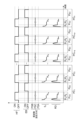
- FIG. 6 is a timing chart of an example related to a plasma processing apparatus according to another exemplary embodiment.
- FIG. 6 shows a timing chart of the source high frequency power HF, the electric bias EB, the frequency setting method, the source frequency f S , and the reflection degree RD in the second embodiment.
- the "HIGH" of the source high frequency power HF indicates that the power level of the source high frequency power HF is higher than the power level of the source high frequency power HF indicated by "LOW”.
- the "OFF" of the source high frequency power HF indicates that the supply of the source high frequency power HF is stopped.
- FIG. 6 shows a timing chart of an example related to a plasma processing apparatus according to another exemplary embodiment.
- FIG. 6 shows a timing chart of the source high frequency power HF, the electric bias EB, the frequency setting method, the source frequency f S , and the reflection degree RD in the second embodiment.
- the "HIGH" of the source high frequency power HF indicates that the power level of the source high frequency power HF
- the frequency setting method indicates the setting method of the source frequency f S.
- the frequency setting method includes a start-up process FSA, a sequential feedback process FSB, and an inter-pulse feedback process FSC.
- the high frequency power supply 31 is configured to supply a source high frequency power HF in one of two periods in each of a plurality of pulse periods PC (i.e., pulse periods PC1 , PC2 , ).
- the plurality of pulse periods PC appear in sequence.
- Each of the plurality of pulse periods PC includes periods PBO and PHO .
- the period PHO is one of the two periods in each of the plurality of pulse periods PC, and the period PBO is the other period.
- the high frequency power supply 31 supplies source high frequency power HF whose power level is indicated as "LOW” in a period P HO in each of the multiple pulse periods PC. Also, the high frequency power supply 31 supplies source high frequency power HF whose power level is indicated as "HIGH” in a period P BO in each of the multiple pulse periods PC. That is, the power level of the source high frequency power HF in the period P HO in each of the multiple pulse periods PC is lower than the power level of the source high frequency power HF in the period P BO in each of the multiple pulse periods PC. Note that the power level of the source high frequency power HF in the period P HO in each of the multiple pulse periods PC may be higher than the power level of the source high frequency power HF in the period P BO in each of the multiple pulse periods PC.
- the bias power supply 32 stops supplying the electric bias EB to the substrate support 11 during the period P HO . Also, the bias power supply 32 supplies the electric bias EB to the substrate support 11 during the period P BO . That is, the period P HO is an independent supply period during which the source high frequency power HF is supplied alone without supplying the electric bias EB.
- the period P HO i.e., the single supply period, includes a ramp-up period P S including its start point.
- the ramp-up period P S may include a period of plasma ignition.
- the period P HO may further include a period P B.
- the ramp-up period P S is a period before the period P B.
- the period P B may be a period following the ramp-up period P S.
- the control unit 30c performs the ramp-up process FSA in the ramp-up period PS in each of one or more consecutive pulse periods including at least the first pulse period PC1 among the multiple pulse periods PC. Specifically, the control unit 30c changes the source frequency fS according to the initial frequency set during the period from the start to the end of the ramp-up period PS .
- the initial frequency set is prepared in advance and stored in a storage unit accessible by the control unit 30c. The initial frequency set may be experimentally obtained or may be determined based on past processing results.
- the number of one or more consecutive pulse periods including the first pulse period PC1 may be 2 or more and 20 or less.
- the control unit 30c performs pulse-to-pulse feedback processing FSC. Specifically, the control unit 30c sets the source frequency f S at each phase in the rising period P S of the pulse period PC n so as to suppress the degree of reflection of the source high frequency power HF at the same phase in the pulse period PC n in accordance with the change from the source frequency f S at the same phase in the pulse period PC n - q to the source frequency f S at the same phase in the pulse period PC n-p , and the change from the degree of reflection of the source high frequency power HF at the same phase in the pulse period PC n-q to the degree of reflection of the source high frequency power HF at the same phase in the pulse period PC n-p.
- the phase in the pulse period PC n is a time point in the pulse period PC n that is determined by the elapsed time from the start point of the pulse period PC n . Therefore, the same phase in a plurality of pulse periods is a time point having the same elapsed time from the start point of the corresponding pulse period.
- pulse period PC n , pulse period PC n-q , and pulse period PC n-p are the nth pulse period, the (n-q)th pulse period, and the (n-p)th pulse period, among the multiple pulse periods PC.
- q and p are integers of 1 or more, and q is greater than p. For example, q is 2 and p is 1.
- phase in the ramp-up period P S in the pulse period PC n is represented as phase ⁇ m .
- Phase ⁇ m is the phase after m hours have elapsed from the start of the ramp-up period P S.
- the control unit 30c sets the frequency obtained by giving the source frequency f S [n-p, ⁇ m ] a change in the same direction as the change from the source frequency f S [n-q, ⁇ m ] to the source frequency f S [n-p, ⁇ m ] as the source frequency f S [n, ⁇ m ].
- the source frequency f S [n, ⁇ m ] is the source frequency f S at phase ⁇ m in the ramp-up period P S in the pulse period PC n . If the change from the degree of reflection of the source high frequency power HF at phase ⁇ m in the rise period PS in the pulse period PCn- q to the degree of reflection of the source high frequency power HF at phase ⁇ m in the rise period PS in the pulse period PCn-p is an increase in the degree of reflection, the control unit 30c sets as the source frequency fS [n, ⁇ m ] the frequency obtained by giving the source frequency fS [np, ⁇ m ] a change in the opposite direction to the change from the source frequency fS [nq, ⁇ m ] to the source frequency fS [np, ⁇ m ].
- control unit 30c may perform the above-mentioned sequential feedback process FSB in a period P B in each of the multiple pulse periods PC.
- the period P B may start after a predetermined time has elapsed from the start of the period P HO .
- the period P B may start when the amount of change in the degree of reflection becomes equal to or less than a designated value in the start-up period P S.
- the time length of the rise period PS in each of the one or more consecutive pulse periods including the initial pulse period PC1 and the time length of the rise period PS in each pulse period after the one or more consecutive pulse periods may be the same as or different from each other.
- control unit 30c may first perform the start-up process FSA, then the inter-pulse feedback process FSC, and then the sequential feedback process FSB in the period P HO in each of the multiple pulse periods PC, as shown in Fig. 7.
- control unit 30c may perform only the inter-pulse feedback process FSC in the period P HO in each of the multiple pulse periods PC.
- the source frequency f S from the start to the end of the period P HO in at least the first and second pulse periods PC may be changed according to another initial frequency set.
- the period P HO in each of the multiple pulse periods PC may be divided into multiple sub-periods, and the above-mentioned inter-pulse feedback process FSC may be applied to each of the multiple sub-periods as each phase in the period P HO .
- the time length of each of the multiple sub-periods is, for example, 10 nsec or more and 10 ⁇ sec or less.
- the source frequency f s may be set to a single frequency or may be set to multiple frequencies.
- the power level of the source high frequency power HF in the period P HO in each of the multiple pulse periods PC may be changed to multiple levels within the period P HO .
- the period P HO may be divided into multiple division periods for each power level of the source high frequency power HF, and the ramp-up process FSA, the inter-pulse feedback process FSC, and the sequential feedback process FSB may be performed in each of the multiple division periods.
- the power level of the source high frequency power HF in the period P HO in each of the multiple pulse periods PC is changed to multiple levels within the period P HO .
- the period P HO in each of the multiple pulse periods PC may include one or more periods in which the power level of the source high frequency power HF has a level indicated by "LOW” and one or more periods in which the power level of the source high frequency power HF has a level indicated by "OFF".
- the level indicated by "LOW” is lower than the level indicated by "HIGH”.
- the level indicated by "OFF” is zero .
- the supply of the source high frequency power HF is stopped.
- the source high frequency power having the level indicated by "LOW” is supplied in two periods including the start point (period P S ) and the end point in the period P HO in each of the multiple pulse periods PC, and the supply of the source high frequency power HF is stopped in the period between these two periods.
- only the inter-pulse feedback process FSC may be performed in each period PHO of the multiple pulse periods PC.
- the ramp-up process FSA may be performed in a period including the start point in each period PHO of the multiple pulse periods PC, and only the inter-pulse feedback process FSC may be performed in other periods within the period PHO .
- the source frequency fS from the start point to the end point of the period PHO in at least the first and second pulse periods among the multiple pulse periods PC may be changed according to another initial frequency set.
- the degree of reflection of the source high frequency power HF is reduced during the period P HO in which the source high frequency power HF is supplied alone.
- the rise time to plasma stability can be accelerated.
- abnormal discharge of plasma can be suppressed.
- the reproducibility of the effective power level (load power level) of the source high frequency power HF is improved. For example, when the power level of the source high frequency power HF is changed to a plurality of power levels during the period P HO , the reproducibility of the effective power level (load power level) corresponding to each power level is improved.
- the reflection is suppressed by adjusting the source frequency f S , so that the operation of the variable capacitance capacitor of the matching device 31m is reduced, and the life of the variable capacitance capacitor can be improved.
- FIG. 9 is a timing chart of an example related to a plasma processing apparatus according to yet another exemplary embodiment.
- FIG. 9 shows a timing chart of the source high frequency power HF, the electric bias EB, the frequency setting method, the source frequency fS , and the degree of reflection RD in the third embodiment.
- "ON" of the source high frequency power HF indicates that the source high frequency power HF is being supplied
- "OFF" of the source high frequency power HF indicates that the supply of the source high frequency power HF is stopped.
- FIG. 9 is a timing chart of an example related to a plasma processing apparatus according to yet another exemplary embodiment.
- FIG. 9 shows a timing chart of the source high frequency power HF, the electric bias EB, the frequency setting method, the source frequency fS , and the degree of reflection RD in the third embodiment.
- "ON" of the source high frequency power HF indicates that the source high frequency power HF is being supplied
- "OFF" of the source high frequency power HF indicates that the supply of the source high frequency
- the frequency setting method indicates the setting method of the source frequency fS .
- the frequency setting method includes a start-up process FSA, a sequential feedback process FSB, and an inter-pulse feedback process FSC. The third embodiment will be described below from the viewpoint of the differences between the second and third embodiments.
- the high frequency power supply 31 supplies the source high frequency power HF in the period P HO .
- the high frequency power supply 31 stops the supply of the source high frequency power HF in the period P BO . That is, in the third embodiment, the high frequency power supply 31 stops the supply of the source high frequency power HF during the period in which the electric bias EB is being supplied.
- the process of setting the source frequency f S in the period P HO in the third embodiment is similar to the process of setting the source frequency f S in the period P HO in the second embodiment.
- the time length of the rise period PS in each of the one or more consecutive pulse periods including the initial pulse period PC1 and the time length of the rise period PS in each pulse period after the one or more consecutive pulse periods may be the same as or different from each other.
- control unit 30c may first perform the start-up process FSA, then the inter-pulse feedback process FSC, and then the sequential feedback process FSB in the period P HO in each of the multiple pulse periods PC, as shown in Fig. 10.
- control unit 30c may perform only the inter-pulse feedback process FSC in the period P HO in each of the multiple pulse periods PC.
- the source frequency f S from the start to the end of the period P HO in at least the first and second pulse periods PC may be changed according to another initial frequency set.
- the period P HO in each of the multiple pulse periods PC may be divided into multiple sub-periods, and the above-mentioned inter-pulse feedback process FSC may be applied to each of the multiple sub-periods as each phase in the period P HO .
- the time length of each of the multiple sub-periods is, for example, 10 nsec or more and 10 ⁇ sec or less.
- the source frequency f s may be set to a single frequency or may be set to multiple frequencies.
- the power level of the source high frequency power HF in the period P HO in each of the multiple pulse periods PC may be changed to multiple levels within the period P HO .
- the period P HO may be divided into multiple division periods for each power level of the source high frequency power HF, and the ramp-up process FSA, the inter-pulse feedback process FSC, and the sequential feedback process FSB may be performed in each of the multiple division periods.
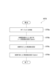
- FIG. 11 is a flow diagram of a frequency control method according to another exemplary embodiment.
- FIG. 11 shows a flow of the frequency control method in each period P HO of a plurality of pulse periods PC.
- the frequency control method shown in FIG. 11 (hereinafter, referred to as "method MTB") may be performed in a state in which a substrate W is placed on a substrate support 11 in a chamber 10.
- a plasma process may be performed on the substrate W.
- the plasma process in method MTB may include plasma etching on the substrate W.
- the method MTB starts with a step STBa, which is performed during a period P HO in each of a plurality of pulse periods PC.
- a pulse of source high frequency power HF is supplied from the high frequency power supply 31 to generate plasma from the gas in the chamber 10.
- the method MTB may further include a step STBb.
- the step STBb is performed in a start-up period PS in each of one or more consecutive pulse periods including a first pulse period among the plurality of pulse periods PC.
- the above-mentioned start-up process FSA is performed.
- the above-mentioned inter-pulse feedback process FSC is performed.
- the inter-pulse feedback process FSC may be performed in the rising period P S in each pulse period after one or more consecutive pulse periods including the first pulse period among the plurality of pulse periods PC.
- the inter-pulse feedback process FSC may be performed in the entire period P HO of each of the plurality of pulse periods PC.
- the inter-pulse feedback process FSC may be performed after the rising process FSA in the period P HO of each of the plurality of pulse periods PC.
- the method MTB may further include a step STBd.
- the step STBd the above-mentioned sequential feedback process FSB is performed.
- the sequential feedback process FSB may be performed after the rise period P S in the period P HO in the plurality of pulse periods PC.
- the sequential feedback process FSB may be performed after the inter-pulse feedback process FSC that is performed following the rise process FSA in the period P HO in the plurality of pulse periods PC.
- the plasma processing apparatus may be an inductively coupled plasma processing apparatus.
- source high frequency power HF is supplied to an antenna.
- a chamber a substrate support disposed within the chamber; a radio frequency power source configured to provide a source radio frequency power to generate a plasma from a gas in the chamber;
- a control unit Equipped with the control unit is configured to set a source frequency of the source high frequency power when the source high frequency power is supplied alone, in accordance with the source frequency when the source high frequency power was previously supplied alone and a degree of reflection of the source high frequency power, so as to suppress a degree of reflection of the source high frequency power.
- Plasma processing equipment is configured to set a source frequency of the source high frequency power when the source high frequency power is supplied alone, in accordance with the source frequency when the source high frequency power was previously supplied alone and a degree of reflection of the source high frequency power, so as to suppress a degree of reflection of the source high frequency power.
- the high frequency power supply is configured to continuously supply the source high frequency power within a single supply period;
- the single supply period includes a plurality of sub-periods;
- the control unit is configured to set the source frequency in an i-th sub-period among the plurality of sub-periods in accordance with the source frequency and a degree of reflection of the source high frequency power in each of one or more sub-periods prior to the i-th sub-period among the plurality of sub-periods, so as to suppress a degree of reflection of the source high frequency power.
- the plasma processing apparatus according to E1.
- the one or more subperiods include a first subperiod and a second subperiod subsequent to the first subperiod;
- the control unit is setting the source frequency in the second subperiod to a frequency different from the source frequency in the first subperiod; setting the source frequency in the i-th subperiod so as to suppress a degree of reflection of the source high frequency power in response to a change from the source frequency in the first subperiod to the source frequency in the second subperiod and a change from a degree of reflection of the source high frequency power in the first subperiod to a degree of reflection of the source high frequency power in the second subperiod;
- the plasma processing apparatus according to E2,
- the single supply period further includes a ramp-up period prior to the plurality of sub-periods, the ramp-up period including a start point of the single supply period;
- the control unit is configured to vary the source frequency according to an initial frequency set during a period from the start to the end of the ramp-up period.
- the plasma processing apparatus further comprises a bias power supply electrically coupled to the substrate support and configured to provide an electrical bias to the substrate support for ion attraction; the single supply period is a period during which the electrical bias from the bias power supply is not supplied to the substrate support;
- the plasma processing apparatus according to any one of E2 to E4.
- the plasma processing apparatus further comprises a bias power supply electrically coupled to the substrate support and configured to provide an electrical bias to the substrate support for ion attraction;
- the radio frequency power source is configured to supply the source radio frequency power during one of two periods in each of a plurality of pulse periods;
- the bias power supply is configured to stop supplying the electric bias to the substrate support during one of the two periods in each of the plurality of pulse periods and to supply the electric bias to the substrate support during the other of the two periods;
- the one period includes a start-up period including a start point thereof;
- the control unit is configured to set the source frequency at each phase in the rise period within the one period in an n-th pulse period among the multiple pulse periods, in accordance with a change from the source frequency at the same phase in an (n-q)th pulse period among the multiple pulse periods to the source frequency at the same phase in an (n-p)th pulse period among the multiple pulse periods, and a change from a degree of reflection of the source high frequency power at the same phase in the (n-
- control unit is configured to change the source frequency according to an initial frequency set from a start to an end of the ramp-up period in each of one or more consecutive pulse periods including at least a first pulse period of the plurality of pulse periods.
- Each of the plurality of pulse periods includes a plurality of sub-periods following the ramp-up period; the control unit is configured to set the source frequency in an i-th sub-period among the plurality of sub-periods of each of the plurality of pulse periods, in accordance with the source frequency and a degree of reflection of the source high frequency power in each of one or more sub-periods prior to the i-th sub-period among the plurality of sub-periods, so as to suppress a degree of reflection of the source high frequency power.
- the plasma processing apparatus according to E6 or E7.
- the one or more subperiods include a first subperiod and a second subperiod subsequent to the first subperiod;
- the control unit is setting the source frequency in the second subperiod to a frequency different from the source frequency in the first subperiod; setting the source frequency in the i-th subperiod so as to suppress a degree of reflection of the source high frequency power in response to a change from the source frequency in the first subperiod to the source frequency in the second subperiod and a change from a degree of reflection of the source high frequency power in the first subperiod to a degree of reflection of the source high frequency power in the second subperiod;
- the plasma processing apparatus according to E8,
- a radio frequency power source configured to provide a source radio frequency power to generate a plasma from a gas in a chamber of the plasma processing apparatus;
- a control unit; Equipped with the control unit is configured to set a source frequency of the source high frequency power when the source high frequency power is supplied alone, in accordance with the source frequency when the source high frequency power was previously supplied alone and a degree of reflection of the source high frequency power, so as to suppress a degree of reflection of the source high frequency power. Power supply system.
- E14 (a) providing a source radio frequency power from a radio frequency power source to generate a plasma from a gas in a chamber of a plasma processing device; (b) in the step (a), setting a source frequency of the source high frequency power when the source high frequency power is supplied alone, in accordance with the source frequency when the source high frequency power was previously supplied alone and the degree of reflection of the source high frequency power, so as to suppress the degree of reflection of the source high frequency power;
- a frequency control method comprising:
- Plasma processing device 10: Chamber, 11: Substrate support, 31: High frequency power source, 32: Bias power source, 30c: Control unit.
Landscapes
- Physics & Mathematics (AREA)
- Engineering & Computer Science (AREA)
- Plasma & Fusion (AREA)
- Chemical & Material Sciences (AREA)
- Analytical Chemistry (AREA)
- Electromagnetism (AREA)
- Spectroscopy & Molecular Physics (AREA)
- Plasma Technology (AREA)
- Drying Of Semiconductors (AREA)
Priority Applications (6)
| Application Number | Priority Date | Filing Date | Title |
|---|---|---|---|
| KR1020247042040A KR102905047B1 (ko) | 2022-10-07 | 2023-09-26 | 플라즈마 처리 장치, 전원 시스템, 및 주파수 제어 방법 |
| KR1020257042468A KR20260006694A (ko) | 2022-10-07 | 2023-09-26 | 플라즈마 처리 장치, 전원 시스템, 및 주파수 제어 방법 |
| JP2024555743A JP7612949B2 (ja) | 2022-10-07 | 2023-09-26 | プラズマ処理装置、電源システム、及び周波数制御方法 |
| CN202380049744.XA CN119923954A (zh) | 2022-10-07 | 2023-09-26 | 等离子体处理装置、电源系统和频率控制方法 |
| JP2024227718A JP2025041838A (ja) | 2022-10-07 | 2024-12-24 | プラズマ処理装置、電源システム、及び周波数制御方法 |
| US19/000,700 US20250132129A1 (en) | 2022-10-07 | 2024-12-24 | Frequency control of source radio frequency power in plasma processing |
Applications Claiming Priority (4)
| Application Number | Priority Date | Filing Date | Title |
|---|---|---|---|
| JP2022162643 | 2022-10-07 | ||
| JP2022-162643 | 2022-10-07 | ||
| JP2022178137 | 2022-11-07 | ||
| JP2022-178137 | 2022-11-07 |
Related Child Applications (1)
| Application Number | Title | Priority Date | Filing Date |
|---|---|---|---|
| US19/000,700 Continuation US20250132129A1 (en) | 2022-10-07 | 2024-12-24 | Frequency control of source radio frequency power in plasma processing |
Publications (1)
| Publication Number | Publication Date |
|---|---|
| WO2024075596A1 true WO2024075596A1 (ja) | 2024-04-11 |
Family
ID=90608317
Family Applications (1)
| Application Number | Title | Priority Date | Filing Date |
|---|---|---|---|
| PCT/JP2023/034969 Ceased WO2024075596A1 (ja) | 2022-10-07 | 2023-09-26 | プラズマ処理装置、電源システム、及び周波数制御方法 |
Country Status (5)
| Country | Link |
|---|---|
| US (1) | US20250132129A1 (https=) |
| JP (2) | JP7612949B2 (https=) |
| KR (2) | KR102905047B1 (https=) |
| CN (1) | CN119923954A (https=) |
| WO (1) | WO2024075596A1 (https=) |
Cited By (1)
| Publication number | Priority date | Publication date | Assignee | Title |
|---|---|---|---|---|
| WO2026053764A1 (ja) * | 2024-09-05 | 2026-03-12 | 東京エレクトロン株式会社 | プラズマ処理装置、電源システム、及びプラズマ処理方法 |
Citations (2)
| Publication number | Priority date | Publication date | Assignee | Title |
|---|---|---|---|---|
| US20210050185A1 (en) * | 2019-08-13 | 2021-02-18 | Mks Instruments, Inc. | Method And Apparatus To Enhance Sheath Formation, Evolution And Pulse To Pulse Stability In RF Powered Plasma Applications |
| JP2021534545A (ja) * | 2018-08-14 | 2021-12-09 | 東京エレクトロン株式会社 | プラズマ処理のための制御のシステム及び方法 |
Family Cites Families (1)
| Publication number | Priority date | Publication date | Assignee | Title |
|---|---|---|---|---|
| JP5319150B2 (ja) | 2008-03-31 | 2013-10-16 | 東京エレクトロン株式会社 | プラズマ処理装置及びプラズマ処理方法及びコンピュータ読み取り可能な記憶媒体 |
-
2023
- 2023-09-26 KR KR1020247042040A patent/KR102905047B1/ko active Active
- 2023-09-26 WO PCT/JP2023/034969 patent/WO2024075596A1/ja not_active Ceased
- 2023-09-26 JP JP2024555743A patent/JP7612949B2/ja active Active
- 2023-09-26 CN CN202380049744.XA patent/CN119923954A/zh active Pending
- 2023-09-26 KR KR1020257042468A patent/KR20260006694A/ko active Pending
-
2024
- 2024-12-24 JP JP2024227718A patent/JP2025041838A/ja active Pending
- 2024-12-24 US US19/000,700 patent/US20250132129A1/en active Pending
Patent Citations (2)
| Publication number | Priority date | Publication date | Assignee | Title |
|---|---|---|---|---|
| JP2021534545A (ja) * | 2018-08-14 | 2021-12-09 | 東京エレクトロン株式会社 | プラズマ処理のための制御のシステム及び方法 |
| US20210050185A1 (en) * | 2019-08-13 | 2021-02-18 | Mks Instruments, Inc. | Method And Apparatus To Enhance Sheath Formation, Evolution And Pulse To Pulse Stability In RF Powered Plasma Applications |
Cited By (1)
| Publication number | Priority date | Publication date | Assignee | Title |
|---|---|---|---|---|
| WO2026053764A1 (ja) * | 2024-09-05 | 2026-03-12 | 東京エレクトロン株式会社 | プラズマ処理装置、電源システム、及びプラズマ処理方法 |
Also Published As
| Publication number | Publication date |
|---|---|
| KR20250025370A (ko) | 2025-02-21 |
| TW202431341A (zh) | 2024-08-01 |
| KR20260006694A (ko) | 2026-01-13 |
| JPWO2024075596A1 (https=) | 2024-04-11 |
| JP7612949B2 (ja) | 2025-01-14 |
| JP2025041838A (ja) | 2025-03-26 |
| KR102905047B1 (ko) | 2025-12-29 |
| US20250132129A1 (en) | 2025-04-24 |
| CN119923954A (zh) | 2025-05-02 |
Similar Documents
| Publication | Publication Date | Title |
|---|---|---|
| JP7634755B2 (ja) | プラズマ処理装置、制御方法、プログラム及び電源システム | |
| JP2015090770A (ja) | プラズマ処理装置 | |
| KR102786710B1 (ko) | 플라즈마 처리 장치 및 소스 고주파 전력의 소스 주파수를 제어하는 방법 | |
| JP2023001473A (ja) | プラズマ処理装置及びプラズマ処理方法 | |
| JP2025041838A (ja) | プラズマ処理装置、電源システム、及び周波数制御方法 | |
| WO2023127655A1 (ja) | プラズマ処理装置、電源システム、制御方法、プログラム、及び記憶媒体 | |
| JP7577093B2 (ja) | プラズマ処理システムおよびプラズマ処理方法 | |
| WO2024004766A1 (ja) | プラズマ処理装置及びプラズマ処理方法 | |
| WO2023022041A1 (ja) | 静電チャック、基板支持器及び基板処理装置 | |
| TWI920462B (zh) | 電漿處理裝置、電源系統及頻率控制方法 | |
| US20240194514A1 (en) | Substrate support and substrate processing apparatus | |
| US20240170255A1 (en) | Voltage waveform controlling method, substrate processing method, and substrate processing apparatus | |
| WO2023182048A1 (ja) | 静電チャック及びプラズマ処理装置 | |
| KR20230115905A (ko) | 에칭 방법 및 플라즈마 처리 장치 | |
| WO2023157682A1 (ja) | エッジリングの消耗量を求める方法、プラズマ処理装置、及び基板処理システム | |
| CN117916862A (zh) | 基片支承器和基片处理装置 | |
| WO2026053764A1 (ja) | プラズマ処理装置、電源システム、及びプラズマ処理方法 | |
| US20250246416A1 (en) | Substrate support and plasma processing apparatus | |
| JP2022185241A (ja) | プラズマ処理装置及びプラズマ処理方法 | |
| WO2024106256A1 (ja) | プラズマ処理装置及びプラズマ処理方法 | |
| TW202431524A (zh) | 基板處理裝置及靜電吸盤 | |
| WO2025211080A1 (ja) | プラズマ処理システム及び周波数最適化方法 | |
| TW202403829A (zh) | 電漿處理裝置及電漿處理方法 | |
| WO2025182632A1 (ja) | プラズマ処理装置 | |
| WO2024106257A1 (ja) | プラズマ処理装置及びプラズマ処理方法 |
Legal Events
| Date | Code | Title | Description |
|---|---|---|---|
| 121 | Ep: the epo has been informed by wipo that ep was designated in this application |
Ref document number: 23874724 Country of ref document: EP Kind code of ref document: A1 |
|
| ENP | Entry into the national phase |
Ref document number: 2024555743 Country of ref document: JP Kind code of ref document: A |
|
| WWE | Wipo information: entry into national phase |
Ref document number: 202380049744.X Country of ref document: CN |
|
| WWP | Wipo information: published in national office |
Ref document number: 1020247042040 Country of ref document: KR |
|
| WWE | Wipo information: entry into national phase |
Ref document number: 11202409175U Country of ref document: SG |
|
| WWP | Wipo information: published in national office |
Ref document number: 11202409175U Country of ref document: SG |
|
| WWP | Wipo information: published in national office |
Ref document number: 202380049744.X Country of ref document: CN |
|
| NENP | Non-entry into the national phase |
Ref country code: DE |
|
| 122 | Ep: pct application non-entry in european phase |
Ref document number: 23874724 Country of ref document: EP Kind code of ref document: A1 |