WO2024075587A1 - 潤滑剤シール装置、及び回転機械 - Google Patents
潤滑剤シール装置、及び回転機械 Download PDFInfo
- Publication number
- WO2024075587A1 WO2024075587A1 PCT/JP2023/034850 JP2023034850W WO2024075587A1 WO 2024075587 A1 WO2024075587 A1 WO 2024075587A1 JP 2023034850 W JP2023034850 W JP 2023034850W WO 2024075587 A1 WO2024075587 A1 WO 2024075587A1
- Authority
- WO
- WIPO (PCT)
- Prior art keywords
- annular portion
- rotating
- stationary
- lubricant
- side annular
- Prior art date
- Legal status (The legal status is an assumption and is not a legal conclusion. Google has not performed a legal analysis and makes no representation as to the accuracy of the status listed.)
- Ceased
Links
Images




Classifications
-
- F—MECHANICAL ENGINEERING; LIGHTING; HEATING; WEAPONS; BLASTING
- F16—ENGINEERING ELEMENTS AND UNITS; GENERAL MEASURES FOR PRODUCING AND MAINTAINING EFFECTIVE FUNCTIONING OF MACHINES OR INSTALLATIONS; THERMAL INSULATION IN GENERAL
- F16C—SHAFTS; FLEXIBLE SHAFTS; ELEMENTS OR CRANKSHAFT MECHANISMS; ROTARY BODIES OTHER THAN GEARING ELEMENTS; BEARINGS
- F16C19/00—Bearings with rolling contact, for exclusively rotary movement
- F16C19/02—Bearings with rolling contact, for exclusively rotary movement with bearing balls essentially of the same size in one or more circular rows
- F16C19/04—Bearings with rolling contact, for exclusively rotary movement with bearing balls essentially of the same size in one or more circular rows for radial load mainly
- F16C19/06—Bearings with rolling contact, for exclusively rotary movement with bearing balls essentially of the same size in one or more circular rows for radial load mainly with a single row or balls
-
- F—MECHANICAL ENGINEERING; LIGHTING; HEATING; WEAPONS; BLASTING
- F16—ENGINEERING ELEMENTS AND UNITS; GENERAL MEASURES FOR PRODUCING AND MAINTAINING EFFECTIVE FUNCTIONING OF MACHINES OR INSTALLATIONS; THERMAL INSULATION IN GENERAL
- F16C—SHAFTS; FLEXIBLE SHAFTS; ELEMENTS OR CRANKSHAFT MECHANISMS; ROTARY BODIES OTHER THAN GEARING ELEMENTS; BEARINGS
- F16C33/00—Parts of bearings; Special methods for making bearings or parts thereof
- F16C33/30—Parts of ball or roller bearings
- F16C33/66—Special parts or details in view of lubrication
-
- F—MECHANICAL ENGINEERING; LIGHTING; HEATING; WEAPONS; BLASTING
- F16—ENGINEERING ELEMENTS AND UNITS; GENERAL MEASURES FOR PRODUCING AND MAINTAINING EFFECTIVE FUNCTIONING OF MACHINES OR INSTALLATIONS; THERMAL INSULATION IN GENERAL
- F16C—SHAFTS; FLEXIBLE SHAFTS; ELEMENTS OR CRANKSHAFT MECHANISMS; ROTARY BODIES OTHER THAN GEARING ELEMENTS; BEARINGS
- F16C33/00—Parts of bearings; Special methods for making bearings or parts thereof
- F16C33/72—Sealings
- F16C33/76—Sealings of ball or roller bearings
- F16C33/80—Labyrinth sealings
-
- F—MECHANICAL ENGINEERING; LIGHTING; HEATING; WEAPONS; BLASTING
- F16—ENGINEERING ELEMENTS AND UNITS; GENERAL MEASURES FOR PRODUCING AND MAINTAINING EFFECTIVE FUNCTIONING OF MACHINES OR INSTALLATIONS; THERMAL INSULATION IN GENERAL
- F16J—PISTONS; CYLINDERS; SEALINGS
- F16J15/00—Sealings
- F16J15/44—Free-space packings
- F16J15/447—Labyrinth packings
Definitions
- a bearing device is provided between the rotating member (rotating shaft) and the stationary member (housing, etc.) of a rotating machine to rotatably support the rotating member.
- a lubricant is supplied to the bearing device.
- a lubricant is a highly viscous substance called grease.
- a lubricant seal device is used to retain this grease within and around the bearing device itself.
- Patent Document 1 A specific example of a lubricant sealing device is described in Patent Document 1 below.
- the device according to Patent Document 1 below is configured to seal the space between a rotating member and a stationary member, thereby sealing the lubricant between the rotating member and the bearing device.
- the device is also formed with a pressure relief flow path for releasing air (pressure) within the sealed space when filling the sealed space with lubricant.
- air pressure
- the present disclosure has been made to solve the above problems, and aims to provide a lubricant seal device and rotating machine that can operate the bearing device more stably by suppressing leakage of lubricant during filling.
- the lubricant seal device for retaining a lubricant supplied to a bearing device provided between a rotating shaft rotatable about its axis and a stationary member surrounding the rotating shaft from its outer periphery in a space between the bearing device
- the lubricant seal device includes a rotating side seal member provided on the outer periphery of the rotating shaft, which has a rotating side annular portion that forms an annular shape centered on the axis and protrudes outward to the outer periphery, and a stationary side seal member provided on the stationary member, which has a stationary side annular portion that faces the rotating side annular portion without contacting it, thereby forming a closed space between the rotating side annular portion and the stationary side annular portion, and either the rotating side annular portion or the stationary side annular portion is deformable so as to abut against the other from the axial direction due to the pressure when the lubricant is filled into the space.
- the rotating machine includes the rotating shaft, the stationary member, the bearing device provided between the rotating shaft and the stationary member, and the lubricant seal device described above.
- This disclosure provides a lubricant seal device and a rotating machine that can operate the bearing device more stably by suppressing leakage of lubricant during filling.
- FIG. 1 is a cross-sectional view showing a configuration of a rotating machine and a lubricant seal device according to a first embodiment of the present disclosure.
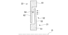
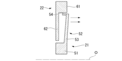
- 5A to 5C are explanatory diagrams showing an example of an operation of the lubricant seal device according to the first embodiment of the present disclosure.
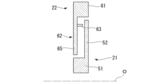
- FIG. 2 is a cross-sectional view showing a first modified example of the lubricant seal device according to the first embodiment of the present disclosure.
- FIG. 4 is a cross-sectional view showing a second modified example of the lubricant seal device according to the first embodiment of the present disclosure.
- FIG. 11 is a diagram showing a second modified example of the lubricant seal device according to the first embodiment of the present disclosure, and is an explanatory diagram showing an example of the operation of the lubricant seal device.
- FIG. 11 is a cross-sectional view showing a third modified example of the lubricant seal device according to the first embodiment of the present disclosure.
- FIG. 11 is a cross-sectional view showing a fourth modified example of the lubricant seal device according to the first embodiment of the present disclosure.
- FIG. 4 is a cross-sectional view showing a configuration of a lubricant seal device according to a second embodiment of the present disclosure.
- FIG. 11 is a cross-sectional view showing a modified example of a lubricant seal device common to each embodiment of the present disclosure.
- the rotary machine 1 is, for example, a gas turbine, a steam turbine, or other mechanical device, and includes a rotating shaft 10, a housing 11 (stationary member), a bearing device 3, and a lubricant seal device 2.
- the rotating shaft 10 is columnar and extends along the axis O, and is rotatable around the axis O.
- the housing 11 is cylindrical and surrounds the rotating shaft 10 from the outer periphery.
- the bearing device 3 is provided between the outer periphery of the rotating shaft 10 and the inner periphery of the housing 11.
- the bearing device 3 is, for example, a ball bearing.
- the bearing device 3 has an inner ring 31, rolling elements 32, and an outer ring 33.
- the inner ring 31 is annular about the axis O.
- the outer ring 33 is annular and surrounds the inner ring 31 from the outer periphery. Between the inner ring 31 and the outer ring 33, there are a plurality of rolling elements 32 arranged at intervals in the circumferential direction.
- the rolling elements 32 are spherical.
- the inner ring 31 is fixed to the outer periphery of the rotating shaft 10.
- the outer ring 33 is fixed to the inner periphery of the housing 11.
- the inner ring 31 fixed to the rotating shaft 10 rotates relative to the outer ring 33.
- multiple rolling elements 32 roll between the inner ring 31 and the outer ring 33. This reduces the frictional resistance between the housing 11 and the rotating shaft 10, and the rotating shaft 10 is supported so that it can rotate freely relative to the housing 11.
- the bearing device 3 also bears the radial load caused by the rotating shaft 10.
- roller bearings other than ball bearings or needle bearings as the bearing device 3.
- the bearing device 3 can be anything as long as it can support the rotating shaft 10 so that it can rotate freely.
- the lubricant seal devices 2 are provided on both sides of the bearing device 3 in the direction of the axis O. Since the pair of lubricant seal devices 2 have a structure that is linearly symmetrical with respect to the bearing device 3, only the lubricant seal device 2 on one side will be described below as a representative example.
- the lubricant seal device 2 is provided to retain the lubricant supplied to the bearing device 3 within the space (filling space 4) formed between the lubricant seal device 2 itself and the bearing device 3.
- the lubricant seal device 2 has a rotating side seal member 21 and a stationary side seal member 22.
- the rotating side annular portion 52 protrudes radially outward from the rotating side base portion 51.
- the rotating side annular portion 52 is provided on the edge of the rotating side base portion 51 that is close to the bearing device 3. In other words, the rotating side annular portion 52 and the end face of the rotating side base portion 51 that faces the lubrication space are flush with each other.
- the rotating side annular portion 52 has a rotating side annular portion main body 53 and a rotating side fin 54.
- the rotating side annular portion main body 53 is a thin-walled annular shape whose dimension in the axial O direction is smaller than that of the rotating side base portion 51.
- the rotating side fin 54 is provided at a radial midpoint of the rotating side annular portion main body 53.
- the rotating side fins 54 protrude from the rotating annular portion main body in the direction of the axis O.
- the rotating side fins 54 are cylindrical with the axis O as their center. In other words, the rotating side fins 54 extend in an annular shape over the entire circumferential area about the axis O. It is desirable that the rotating side fins 54 be provided outside the center of the rotating side annular portion main body 53 in the radial direction.
- the stationary side seal member 22 is fixed to the inner peripheral surface of the housing 11.
- the stationary side seal member 22 has a stationary side base 61 and a stationary side annular portion 62.
- the stationary side base 61 is fitted into the inner peripheral surface of the housing 11 by forming an annular shape centered on the axis O.
- the cross-sectional shape of the stationary side base 61 is, for example, rectangular.
- the stationary side annular portion 62 protrudes radially inward from the stationary side base 61.
- the stationary side annular portion 62 is provided on the edge of the stationary side base 61 that faces away from the bearing device 3. In other words, the end faces of the stationary side annular portion 62 and the stationary side base 61 opposite the lubrication space are flush with each other.
- the stationary side annular portion 62 is a thin-walled annular shape whose dimension in the axial direction O is smaller than that of the stationary side base portion 61.
- the stationary side annular portion 62 faces the above-mentioned rotating side annular portion 52 with a gap in the axial direction O.
- the radially inner end of the stationary side annular portion 62 and the rotating side base portion 51 face each other in the radial direction with a gap extending in the radial direction.
- the radially outer end of the rotating side annular portion 52 and the stationary side base portion 61 face each other in the radial direction with a gap extending in the radial direction.
- the gap between the stationary side annular portion 62 and the rotating side annular portion 52 is defined as a closed space 7.
- the closed space 7 is connected to the filling space 4 through the gap between the rotating side annular portion 52 and the stationary side base portion 61.
- the closed space 7 is also connected to the outside of the filling space 4 through the gap between the stationary side annular portion 62 and the rotating side base portion 51.
- the housing 11 is formed with a supply hole 12 for supplying lubricant to the filling space 4, and a discharge hole 13 for discharging it.
- the lubricant is filled into the filling space 4 through the supply hole 12 while pressure is applied to the lubricant.
- air or old lubricant within the filling space 4 is discharged to the outside through the discharge hole 13.
- the lubricant referred to here mainly refers to highly viscous oils and fats such as grease.
- the lubricant seal device 2 of this embodiment employs the above-mentioned configurations.
- the tip of the rotating side fin 54 protrudes toward the stationary side annular portion 62. Therefore, even under smaller pressure, the rotating side annular portion 52 deforms slightly, and the rotating side fin 54 can be brought into contact with the stationary side annular portion 62 immediately after deformation begins. This makes it possible to more effectively prevent inadvertent leakage of lubricant through the closed space 7. As a result, a predetermined amount of lubricant can be supplied to the filling space 4 without any waste, making it possible to achieve smooth operation of the bearing device 3. This allows the rotating machine 1 to operate more stably.
- a stationary fin 63 can be provided on the stationary annular portion 62 of the stationary seal member 22. That is, the stationary annular portion 62 has a stationary annular portion main body 65 and a stationary fin 63. Also in this case, it is preferable that the stationary fin 63 is provided outside the radial center of the stationary annular portion main body 65.
- FIG. 4 it is also possible to adopt a configuration in which the rotating side fins 54 are provided at the radially outer end of the rotating side annular portion main body 53.
- the closed space 7 is closed, thereby suppressing leakage of the lubricant.
- FIG. 5 when the rotating shaft 10 is rotating, the rotating side fins 54 are deformed so as to fall radially outward due to centrifugal force. This reduces the gap between the rotating side fins 54 and the stationary side seal member 22, making it possible to suppress leakage of the lubricant while the rotating shaft 10 is rotating. Note that it is desirable to appropriately determine the magnitude of the centrifugal force and the material and dimensions of the rotating side seal member 21 so that the rotating side fins 54 and the stationary side seal member 22 do not come into contact with each other while the rotating shaft 10 is rotating.
- the tip surface 55 of the rotating side fin 54 may extend in a direction inclined with respect to the axis O. Specifically, it is desirable to give the tip surface 55 an inclination angle equivalent to the inclination angle ⁇ of the rotating side annular portion main body 53 due to the pressure when filling the lubricant. (Note that the "inclination angle ⁇ " referred to here refers to the average or maximum value of the inclination angle in the extension direction of the rotating side annular portion main body 53.) As a result, when the rotating side annular portion 52 is deformed in the direction of the axis O, the tip surface 55 of the rotating side fin 54 will be aligned with the surface of the stationary side annular portion 62.
- the tip surface 55 of the rotating side fin 54 and the stationary side annular portion 62 are in surface contact. Therefore, compared to when the rotating side fin 54 and the stationary side annular portion 62 are in line contact, the liquid tightness between the rotating side fin 54 and the stationary side annular portion 62 is improved, making it possible to more effectively suppress leakage of the lubricant.
- a storage groove 64 in which the tip of the rotating side fin 54 is accommodated may be formed on the surface of the stationary side annular portion 62. That is, this storage groove 64 is formed at a location where the tip of the rotating side fin 54 is located when the rotating side annular portion 52 is deformed in the direction of the axis O. Furthermore, the tip of the rotating side fin 54 is arc-shaped in a cross-sectional view including the axis O. The storage groove 64 also has a cross-sectional shape following this arc. According to this configuration, when the rotating side annular portion 52 is deformed in the direction of the axis O, the tip of the rotating side fin 54 is accommodated in the storage groove 64.
- the stationary side seal member 22 has a stationary side base portion 61, a stationary side first opposing surface 71, and a stationary side second opposing surface 72.
- the rotating side seal member 21 has a rotating side base portion 51, a rotating side first opposing surface 81, and a rotating side second opposing surface 82.
- the stationary side first opposing surface 71 faces the rotating side annular portion 52 from the direction of axis O. Furthermore, the stationary side second opposing surface 72 faces the rotating side annular portion 52 from the radial direction. This results in a stepped difference between the stationary side first opposing surface 71 and the stationary side second opposing surface 72. Similarly, the rotating side first opposing surface 81 faces the stationary side annular portion 62 from the direction of axis O. Furthermore, the rotating side second opposing surface 82 faces the stationary side annular portion 62 from the radial direction.
- the shape is simpler, which reduces the cost of processing and shortens the construction period. This makes it possible to further reduce the manufacturing and maintenance costs of the device.
- the lubricant seal device 2 described in each embodiment can be understood, for example, as follows.
- the lubricant seal device 2 is a lubricant seal device 2 for retaining a lubricant supplied to a bearing device 3 provided between a rotating shaft 10 rotatable around an axis O and a stationary member surrounding the rotating shaft 10 from the outer periphery, in a space between the bearing device 3, and the lubricant seal device 2 includes a rotating side seal member 21 provided on the outer periphery of the rotating shaft 10, which has a rotating side annular portion 52 that forms an annular shape centered on the axis O and protrudes to the outer periphery, and a stationary side seal member 22 provided on the stationary member, which has a stationary side annular portion 62 that faces the rotating side annular portion 52 without contacting it, thereby forming a closed space 7 between the rotating side annular portion 52 and the stationary side annular portion 62, and either the rotating side annular portion 52 or the stationary side annular portion 62 can be deformed so as to abut against the other from the direction of the axis
- the lubricant seal device 2 according to the second aspect is the lubricant seal device 2 according to the first aspect, and the rotating side annular portion 52 has a rotating side annular portion main body 53 having a circular ring shape centered on the axis O, and a rotating side fin 54 that protrudes from the rotating side annular portion main body 53 toward the stationary side annular portion 62 and has a circular ring shape centered on the axis O.
- the tip of the rotating side fin 54 protrudes toward the stationary side annular portion 62, so that the rotating side annular portion 52 can be deformed and the rotating side fin 54 can be brought into contact with the stationary side annular portion 62 even under smaller pressure. This makes it possible to more effectively prevent inadvertent leakage of lubricant.
- the lubricant seal device 2 of the third aspect is the lubricant seal device 2 of the second aspect, in which the rotating side fin 54 is provided at the radial tip of the rotating side annular portion main body 53.
- the rotating side fins 54 are provided at the tip of the rotating side annular portion main body 53, so that when the lubricant is filled, the rotating side fins 54 come into contact with the stationary side annular portion 62, preventing leakage of the lubricant.
- the rotating side fins 54 are deformed by centrifugal force so as to fall radially outward. This reduces the gap between the rotating side fins 54 and the stationary side seal member 22, making it possible to prevent leakage of the lubricant while the rotating shaft 10 is rotating.
- the lubricant seal device 2 of the fourth aspect is the lubricant seal device 2 of the second or third aspect, in which the tip surface 55 of the rotating side fin 54 is inclined with respect to the axis O so as to follow the surface of the stationary side annular portion 62 when the rotating side annular portion 52 is deformed in the direction of the axis O.
- the tip surface 55 of the rotating side fin 54 is inclined with respect to the axis O.
- the tip portion 52 is deformed in the direction of the axis O, the tip portion conforms to the surface of the stationary side annular portion 62. This improves the liquid-tightness between the rotating side fin 54 and the stationary side annular portion 62, making it possible to more effectively suppress leakage of lubricant.
- the lubricant seal device 2 according to the fifth aspect is the lubricant seal device 2 according to the second or third aspect, and the stationary side annular portion 62 is formed with an accommodation groove 64 in which the tip of the rotating side fin 54 is accommodated when the rotating side annular portion 52 is deformed in the direction of the axis O.
- the lubricant seal device 2 according to the second aspect is a lubricant seal device 2 according to any one of the first to fifth aspects, and the stationary side annular portion 62 has a stationary side annular portion 62 main body having a circular ring shape centered on the axis O, and a stationary side fin 63 that protrudes from the stationary side annular portion 62 main body toward the rotating side annular portion 52 and has a circular ring shape centered on the axis O.
- the tip of the stationary side fin 63 protrudes toward the rotating side annular portion 52, so that the stationary side annular portion 62 can be deformed and the stationary side fin 63 can be brought into contact with the rotating side annular portion 52 even under smaller pressure. This makes it possible to more effectively prevent accidental leakage of lubricant.
- the lubricant seal device 2 of the seventh aspect is the lubricant seal device 2 of the sixth aspect, in which the tip surface 55 of the stationary side fin 63 is inclined with respect to the axis O so as to follow the surface of the rotating side annular portion 52 when the stationary side annular portion 62 is deformed in the direction of the axis O.
- the tip surface 55 of the stationary side fin 63 is inclined with respect to the axis O.
- the tip portion conforms to the surface of the rotating side annular portion 52. This improves the liquid-tightness between the stationary side fin 63 and the rotating side annular portion 52, making it possible to more effectively suppress leakage of lubricant.
- the lubricant seal device 2 according to the eighth aspect is the lubricant seal device 2 according to the sixth aspect, in which the rotating side annular portion 52 is formed with an accommodation groove 64 that accommodates the tip of the stationary side fin 63 when the stationary side annular portion 62 is deformed in the direction of the axis O.
- the lubricant seal device 2 according to the ninth aspect is the lubricant seal device 2 according to the first aspect, in which the stationary side seal member 22 has a stationary side first opposing surface 71 that faces the rotating side annular portion 52 in the direction of the axis O, and a stationary side second opposing surface 72 that faces the rotating side annular portion 52 in the radial direction.
- the rotating side annular portion 52 deforms in the axial O direction due to the pressure of the lubricant, and the rotating side annular portion 52 abuts against the stationary side first opposing surface 71. This closes the closed space 7, allowing the lubricant to leak. Furthermore, when the rotating shaft 10 is rotating, the rotating side annular portion 52 extends radially outward due to centrifugal force, thereby reducing the gap between the rotating side annular portion 52 and the second opposing surface. This also makes it possible to suppress leakage of lubricant while the rotating shaft 10 is rotating.
- the lubricant seal device 2 according to the tenth aspect is the lubricant seal device 2 according to the first aspect, and the rotating side seal member 21 has a rotating side first opposing surface 81 that faces the stationary side annular portion 62 in the direction of the axis O, and a rotating side second opposing surface 82 that faces the stationary side annular portion 62 in the radial direction.
- the stationary side annular portion 62 comes into contact with the rotating side first opposing surface 81 when it is deformed in the axial direction O by the pressure of the lubricant. This closes the closed space 7, allowing the lubricant to leak.
- the rotating side second opposing surface 82 is provided, the gap between the stationary side annular portion 62 and the rotating side second opposing surface 82 can be kept small. This also makes it possible to suppress leakage of lubricant while the rotating shaft 10 is rotating.
- the rotating machine 1 includes the rotating shaft 10, the stationary member, the bearing device 3 provided between the rotating shaft 10 and the stationary member, and the lubricant seal device 2 according to any one of the first to tenth aspects.
- the above configuration prevents leakage of lubricant, allowing the bearing device 3 to operate smoothly. This makes it possible to achieve more stable operation of the rotating machine 1.
Landscapes
- Engineering & Computer Science (AREA)
- General Engineering & Computer Science (AREA)
- Mechanical Engineering (AREA)
- Sealing Using Fluids, Sealing Without Contact, And Removal Of Oil (AREA)
- Sealing Of Bearings (AREA)
- Rolling Contact Bearings (AREA)
Abstract
本開示の潤滑剤シール装置は、軸線回りに回転可能な回転軸、及び静止側部材との間に設けられた軸受装置に供給される潤滑剤を軸受装置との間の空間内で保持するための潤滑剤シール装置であって、回転軸の外周面に設けられ、外周側に張り出す回転側環状部を有する回転側シール部材と、静止側部材に設けられ、回転側環状部に非接触で対向することで閉止空間を形成する静止側環状部を有する静止側シール部材と、を備え、回転側環状部、及び静止側環状部のいずれか一方は、潤滑剤が充填される際の圧力によって、他方に向かって軸線方向から当接するように変形可能である。
Description
本開示は、潤滑剤シール装置、及び回転機械に関する。本願は、2022年10月7日に出願された特願2022-162308号に対して優先権を主張し、その内容をここに援用する。
回転機械の回転側部材(回転軸)と、静止側部材(ハウジング等)との間には、回転側部材を回転可能に支持するための軸受装置が設けられる。軸受装置の円滑な動作を維持するために、当該軸受装置には潤滑剤が供給される。潤滑剤の一例として、グリースと呼ばれる粘性の高い物質が用いられることがある。このグリースを軸受装置自体、及びその周囲で保持するために、潤滑剤シール装置が用いられる。
潤滑剤シール装置の具体例として、下記特許文献1に記載されたものが知られている。下記特許文献1に係る装置は、回転側部材と静止側部材との間をシールすることで、軸受装置との間で潤滑剤を密封するように構成されている。また、当該装置には、潤滑剤を密封空間に充填する際に、密封空間内の空気(圧力)を逃がすための圧力逃がし流路が形成されている。潤滑剤を密封空間に充填する際には、新しい潤滑剤を高圧で供給することで、密封空間内の古い潤滑剤を、圧力逃がし流路とは異なる排出口を通じて外部に押し出す必要がある。
しかしながら、上記特許文献1に係る装置のように、圧力逃がし流路が併設されている場合、新しい潤滑剤が、排出口ではなく、当該圧力逃がし流路を通じて外部に漏洩してしまうことがある。このため、所定の量の潤滑剤が密封空間内に供給されず、軸受装置の安定的な動作を阻害してしまう虞がある。
本開示は上記課題を解決するためになされたものであって、充填時の潤滑剤の漏洩が抑制されることで軸受装置をさらに安定的に動作させることが可能な潤滑剤シール装置、及び回転機械を提供することを目的とする。
上記課題を解決するために、本開示に係る潤滑剤シール装置は、軸線回りに回転可能な回転軸、及び該回転軸を外周側から囲う静止側部材との間に設けられた軸受装置に供給される潤滑剤を該軸受装置との間の空間内で保持するための潤滑剤シール装置であって、前記回転軸の外周面に設けられ、前記軸線を中心とする環状をなすとともに外周側に張り出す回転側環状部を有する回転側シール部材と、前記静止側部材に設けられ、前記回転側環状部に非接触で対向することで該回転側環状部との間に閉止空間を形成する静止側環状部を有する静止側シール部材と、を備え、前記回転側環状部、及び前記静止側環状部のいずれか一方は、前記空間内に前記潤滑剤が充填される際の圧力によって、他方に向かって前記軸線方向から当接するように変形可能である。
本開示に係る回転機械は、前記回転軸と、前記静止側部材と、前記回転軸と前記静止側部材との間に設けられた前記軸受装置と、上記の潤滑剤シール装置と、を備える。
本開示によれば、充填時の潤滑剤の漏洩が抑制されることで軸受装置をさらに安定的に動作させることが可能な潤滑剤シール装置、及び回転機械を提供することができる。
<第一実施形態>
(回転機械の構成)
以下、本開示の第一実施形態に係る回転機械1、及び潤滑剤シール装置2について、図1と図2を参照して説明する。回転機械1は、例えばガスタービンや蒸気タービン、その他の機械装置であり、回転軸10と、ハウジング11(静止側部材)と、軸受装置3と、潤滑剤シール装置2と、を備えている。
(回転機械の構成)
以下、本開示の第一実施形態に係る回転機械1、及び潤滑剤シール装置2について、図1と図2を参照して説明する。回転機械1は、例えばガスタービンや蒸気タービン、その他の機械装置であり、回転軸10と、ハウジング11(静止側部材)と、軸受装置3と、潤滑剤シール装置2と、を備えている。
回転軸10は、軸線Oに沿って延びる柱状をなすとともに当該軸線O回りに回転可能である。ハウジング11は、回転軸10を外周側から囲う筒状をなしている。回転軸10の外周面とハウジング11の内周面との間には、軸受装置3が設けられている。
軸受装置3は、例えば玉軸受である。軸受装置3は、内輪31と、転動体32と、外輪33と、を有している。内輪31は、軸線Oを中心とする円環状をなしている。外輪33は、内輪31を外周側から囲う円環状をなしている。内輪31と外輪33との間には、周方向に間隔をあけて配列された複数の転動体32が介在している。転動体32は、球状をなしている。内輪31は、回転軸10の外周面に固定されている。外輪33は、ハウジング11の内周面に固定されている。
回転軸10が軸線O回りに回転すると、当該回転軸10に固定された内輪31が外輪33に対して相対回転する。このとき、複数の転動体32が内輪31と外輪33との間で転動する。これにより、ハウジング11にと回転軸10との間の摩擦抵抗が低減されて、当該回転軸10がハウジング11に対して相対回転自在に支持された状態となる。また、軸受装置3は、回転軸10による径方向への荷重を負担する。
なお、軸受装置3として、玉軸受以外のローラー軸受や、ニードル軸受を用いることも可能である。つまり、軸受装置3は、回転軸10を回転自在に支持できる限りにおいて、いかなるものでもよい。
(潤滑剤シール装置の構成)
潤滑剤シール装置2は、上記の軸受装置3を挟んで、軸線O方向の両側に1つずつ設けられている。これら一対の潤滑剤シール装置2は、軸受装置3を基準として線対称な構造を有することから、以下では代表的に一方側の潤滑剤シール装置2についてのみ説明する。
潤滑剤シール装置2は、上記の軸受装置3を挟んで、軸線O方向の両側に1つずつ設けられている。これら一対の潤滑剤シール装置2は、軸受装置3を基準として線対称な構造を有することから、以下では代表的に一方側の潤滑剤シール装置2についてのみ説明する。
潤滑剤シール装置2は、軸受装置3に供給される潤滑剤を、潤滑剤シール装置2自体と軸受装置3との間に形成される空間(充填空間4)内で保持するために設けられている。潤滑剤シール装置2は、回転側シール部材21と、静止側シール部材22と、を有する。
回転側シール部材21は、回転軸10の外周面に固定されている。回転側シール部材21は、回転側基部51と、回転側環状部52と、を有する。回転側基部51は、軸線Oを中心とする円環状をなすことで、回転軸10の外周面に外嵌されている。回転側基部51の断面形状は一例として矩形である。
回転側環状部52は、回転側基部51から径方向外側に向かって突出している。回転側環状部52は、回転側基部51における軸受装置3に近接する側の端縁に設けられている。つまり、回転側環状部52と回転側基部51における潤滑空間側の端面は、互いに面一となっている。
回転側環状部52は、回転側環状部本体53と、回転側フィン54と、を有する。回転側環状部本体53は、回転側基部51よりも軸線O方向の寸法が小さい薄肉円環状をなしている。回転側環状部本体53の径方向における中途位置には、回転側フィン54が設けられている。
回転側フィン54は、回転環状部本体から軸線O方向に向かって突出している。また、回転側フィン54は、軸線Oを中心とする円筒状をなしている。つまり、回転側フィン54は、軸線Oに対する周方向の全域にわたって環状に延びている。回転側フィン54が設けられる位置は、回転側環状部本体53の径方向における中央部よりも外側であることが望ましい。
静止側シール部材22は、ハウジング11の内周面に固定されている。静止側シール部材22は、静止側基部61と、静止側環状部62と、を有する。静止側基部61は、軸線Oを中心とする円環状をなすことで、ハウジング11の内周面に内嵌されている。静止側基部61の断面形状は一例として矩形である。
静止側環状部62は、静止側基部61から径方向内側に向かって突出している。静止側環状部62は、静止側基部61における軸受装置3から離間する側の端縁に設けられている。つまり、静止側環状部62と静止側基部61における潤滑空間とは反対側の端面は、互いに面一となっている。
静止側環状部62は、静止側基部61よりも軸線O方向の寸法が小さい薄肉円環状をなしている。静止側環状部62は、上記の回転側環状部52に対して軸線O方向に間隔をあけて対向している。また、静止側環状部62の径方向内側の端部と、回転側基部51は、径方向に広がる隙間を介して互いに径方向から対向している。同様に、回転側環状部52の径方向外側の端部と、静止側基部61は、径方向に広がる隙間を介して互いに径方向から対向している。
これら静止側環状部62、及び回転側環状部52との間の間隙は、閉止空間7とされている。閉止空間7は、回転側環状部52と静止側基部61との間の隙間を通じて充填空間4に連通している。また、閉止空間7は、静止側環状部62と回転側基部51との隙間を通じて、充填空間4の外部と連通している。これにより、これら回転側シール部材21と静止側シール部材22は、充填空間4とその外部との間における潤滑剤の漏洩を抑止するラビリンスシール構造を形成している。
さらに、ハウジング11には、充填空間4に対して潤滑剤を供給するための供給孔12と、排出するための排出孔13と、が形成されている。潤滑剤に圧力をかけながら、供給孔12を通じて充填空間4内に潤滑剤が充填される。潤滑剤の充填と同時に、充填空間4内の空気、又は古い潤滑剤が排出孔13を通じて外部に排出される。なお、ここで言う潤滑剤は、主としてグリースのような粘性の高い油脂を指している。
(作用効果)
次に、潤滑剤シール装置2の動作について説明する。上記のように潤滑剤を充填空間4内に充填する際、潤滑剤は軸受装置3の摺動部を中心として、充填空間4内の各部に行き渡る。なおも潤滑剤を供給し続けると、潤滑剤自体に与えられた圧力によって、充填空間4内の空気、又は古い潤滑剤が排出孔13から外部に排出される。
次に、潤滑剤シール装置2の動作について説明する。上記のように潤滑剤を充填空間4内に充填する際、潤滑剤は軸受装置3の摺動部を中心として、充填空間4内の各部に行き渡る。なおも潤滑剤を供給し続けると、潤滑剤自体に与えられた圧力によって、充填空間4内の空気、又は古い潤滑剤が排出孔13から外部に排出される。
ここで、潤滑剤の圧力が高い場合、潤滑剤シール装置2の閉止空間7を通じて、不用意に潤滑剤が外部に漏洩してしまう場合がある。つまり、本来は排出孔13から排出されるべき潤滑剤が、排出孔13ではなく潤滑剤シール装置2側から外部に漏洩してしまうことがある。この場合、充填空間4内に所定の量の潤滑剤が供給されず、軸受装置3の円滑な動作が阻害されてしまう虞がある。そこで、本実施形態に係る潤滑剤シール装置2は、上述の各構成を採っている。
上記構成によれば、軸受装置3と潤滑剤シール装置2との間の空間内に潤滑剤を充填する際に、潤滑剤の圧力によって回転側環状部52が静止側環状部62に向かって当接するように湾曲(変形)する(図2参照)。これにより、回転側環状部52と静止側環状部62との間の閉止空間7が閉止され、潤滑剤が外部に漏れてしまう可能性を低減することができる。
特に、上記構成によれば、回転側フィン54の先端が静止側環状部62に向かって突出している。このため、より小さな圧力のもとでも、当該回転側環状部52がわずかに変形することで、回転側フィン54を変形開始後直ちに静止側環状部62に当接させることができる。したがって、閉止空間7を通じた潤滑剤の不用意な漏洩をさらに効果的に抑止することができる。その結果、充填空間4に所定の量の潤滑剤を余すことなく供給することができ、軸受装置3の円滑な動作を実現することが可能となる。これにより、回転機械1がより安定的に動作する。
以上、本開示の第一実施形態について説明した。なお、本開示の要旨を逸脱しない限りにおいて、上記の構成に種々の変更や改修を施すことが可能である。例えば、第一変形例として図3に示すように、回転側シール部材21の回転側フィン54に代えて、静止側シール部材22の静止側環状部62に静止側フィン63を設けることも可能である。つまり、静止側環状部62は、静止側環状部本体65と、静止側フィン63と、を有する。また、この場合も静止側フィン63は、静止側環状部本体65の径方向中央よりも外側に設けられることが望ましい。この構成によれば、潤滑剤の供給時の圧力によって回転側環状部52が軸線O方向に変形した際に、当該回転側環状部52と静止側フィン63の先端とが当接する。これにより、閉止空間7が閉止されて、潤滑剤の漏洩を抑制することが可能となる。
さらに、第二変形例として図4に示すように、回転側フィン54が、回転側環状部本体53の径方向外側の端部に設けられている構成を採ることも可能である。この構成でも、上記の各構成と同様に閉止空間7が閉止されることで、潤滑剤の漏洩が抑制される。加えて、図5に示すように、回転軸10が回転している際には、遠心力によって回転側フィン54は径方向外側に倒れるように変形する。これにより、回転側フィン54と静止側シール部材22との間の隙間が小さくなり、回転軸10の回転中における潤滑剤の漏洩をも抑制することが可能となる。なお、回転軸10の回転中には、回転側フィン54と静止側シール部材22とが接触しないように、遠心力の大きさと回転側シール部材21の材質、及び寸法が適宜決定されることが望ましい。
また、第三変形例として図6に示すように、回転側フィン54の先端面55が、軸線Oに対して傾斜する方向に延びていてもよい。具体的には、潤滑剤を充填する際の圧力による回転側環状部本体53の倒れ角θと同等の傾斜角度を先端面55に持たせることが望ましい。(なお、ここで言う「倒れ角θ」は、回転側環状部本体53の延在方向における倒れ角の平均値、又は最大値を指すものである。)これにより、回転側環状部52が軸線O方向に変形した際に、回転側フィン54の先端面55が静止側環状部62の表面に沿うようになる。言い換えると、回転側フィン54の先端面55と静止側環状部62とが面接触する。したがって、これら回転側フィン54と静止側環状部62とが線接触している場合に比べて、回転側フィン54と静止側環状部62との間の液密性が向上し、潤滑剤の漏洩をさらに効果的に抑制することが可能となる。
さらに、第四変形例として図7に示すように、静止側環状部62の表面に、回転側フィン54の先端部が収容される収容溝64が形成されていてもよい。つまり、この収容溝64は、回転側環状部52が軸線O方向に変形した際に、回転側フィン54の先端部が位置する箇所に形成されている。また、回転側フィン54の先端部は軸線Oを含む断面視で円弧状をなしている。収容溝64も、この円弧に倣った断面形状を有している。この構成によれば、回転側環状部52が軸線O方向に変形した際に、回転側フィン54の先端部が収容溝64に収容される。これにより、回転側フィン54と静止側環状部62との間の隙間が小さくなる。また、回転側フィン54と静止側環状部62とが線接触又は面接触している場合に比べて、隙間が湾曲していることから、当該隙間の流路長さが長くなる。したがって、この隙間における潤滑剤の流動抵抗が大きくなり、潤滑剤の漏洩をより一層効果的に抑制することが可能となる。
<第二実施形態>
次に、本開示の第二実施形態について、図8を参照して説明する。なお、上記の第一実施形態、及び各変形例と同様の構成については同一の符号を付し、詳細な説明を省略する。図8に示すように、本実施形態では、静止側シール部材22は、静止側基部61と、静止側第一対向面71と、静止側第二対向面72と、を有する。回転側シール部材21は、回転側基部51と、回転側第一対向面81と、回転側第二対向面82と、を有する。
次に、本開示の第二実施形態について、図8を参照して説明する。なお、上記の第一実施形態、及び各変形例と同様の構成については同一の符号を付し、詳細な説明を省略する。図8に示すように、本実施形態では、静止側シール部材22は、静止側基部61と、静止側第一対向面71と、静止側第二対向面72と、を有する。回転側シール部材21は、回転側基部51と、回転側第一対向面81と、回転側第二対向面82と、を有する。
静止側第一対向面71は、回転側環状部52に対して軸線O方向から対向している。また、静止側第二対向面72は、回転側環状部52に対して径方向から対向している。これにより、静止側第一対向面71と静止側第二対向面72とは階段状の段差を形成している。同様に、回転側第一対向面81は、静止側環状部62に対して軸線O方向から対向している。また、回転側第二対向面82は、静止側環状部62に対して径方向から対向している。
(作用効果)
上記構成によれば、軸受装置3と潤滑剤シール装置2との間の空間内に潤滑剤を充填する際に、潤滑剤の圧力によって回転側環状部52が軸線O方向に変形した際に、当該回転側環状部52は静止側第一対向面71に当接する。これにより、閉止空間7が閉止され、潤滑剤の漏洩をすることが可能となる。さらに、回転軸10が回転している際には、遠心力によって回転側環状部52が径方向外側に延びることから、当該回転側環状部52と第二対向面との間の隙間が小さくなる。これにより、回転軸10の回転中における潤滑剤の漏洩も抑制することができる。
上記構成によれば、軸受装置3と潤滑剤シール装置2との間の空間内に潤滑剤を充填する際に、潤滑剤の圧力によって回転側環状部52が軸線O方向に変形した際に、当該回転側環状部52は静止側第一対向面71に当接する。これにより、閉止空間7が閉止され、潤滑剤の漏洩をすることが可能となる。さらに、回転軸10が回転している際には、遠心力によって回転側環状部52が径方向外側に延びることから、当該回転側環状部52と第二対向面との間の隙間が小さくなる。これにより、回転軸10の回転中における潤滑剤の漏洩も抑制することができる。
加えて、上記第一実施形態のように、回転側フィン54、又は静止側フィン63を設ける場合に比べて、形状が簡素であることから、加工に要するコストの削減と工期の短縮を実現することもできる。これにより、さらに装置の製造コストやメンテナンスコストを削減することが可能となる。
<各実施形態に共通する変形例>
以上、本開示の各実施形態について説明した。なお、本開示の要旨を逸脱しない限りにおいて、上記の各構成に種々の変更や改修を施すことが可能である。各実施形態に共通する変形例として図9に示すように、回転側シール部材21と、静止側シール部材22との位置関係を、各実施形態とは反対にすることが可能である。この場合にも、上述の各変形例の構成を適用することができる。また、上述したものと同様の作用効果を実現することが可能である。
以上、本開示の各実施形態について説明した。なお、本開示の要旨を逸脱しない限りにおいて、上記の各構成に種々の変更や改修を施すことが可能である。各実施形態に共通する変形例として図9に示すように、回転側シール部材21と、静止側シール部材22との位置関係を、各実施形態とは反対にすることが可能である。この場合にも、上述の各変形例の構成を適用することができる。また、上述したものと同様の作用効果を実現することが可能である。
<付記>
各実施形態に記載の潤滑剤シール装置2は、例えば以下のように把握される。
各実施形態に記載の潤滑剤シール装置2は、例えば以下のように把握される。
(1)第1の態様に係る潤滑剤シール装置2は、軸線O回りに回転可能な回転軸10、及び該回転軸10を外周側から囲う静止側部材との間に設けられた軸受装置3に供給される潤滑剤を該軸受装置3との間の空間内で保持するための潤滑剤シール装置2であって、前記回転軸10の外周面に設けられ、前記軸線Oを中心とする環状をなすとともに外周側に張り出す回転側環状部52を有する回転側シール部材21と、前記静止側部材に設けられ、前記回転側環状部52に非接触で対向することで該回転側環状部52との間に閉止空間7を形成する静止側環状部62を有する静止側シール部材22と、を備え、前記回転側環状部52、及び前記静止側環状部62のいずれか一方は、前記空間内に前記潤滑剤が充填される際の圧力によって、他方に向かって前記軸線O方向から当接するように変形可能である。
上記構成によれば、軸受装置3と潤滑剤シール装置2との間の空間内に潤滑剤を充填する際に、潤滑剤の圧力によって回転側環状部52、及び静止側環状部62のいずれか一方が他方に向かって当接するように変形する。これにより、回転側環状部52と静止側環状部62との間の閉止空間7が閉止され、潤滑剤が外部に漏れてしまう可能性を低減することができる。
(2)第2の態様に係る潤滑剤シール装置2は、第1の態様に係る潤滑剤シール装置2であって、前記回転側環状部52は、前記軸線Oを中心とする円環状の回転側環状部本体53と、該回転側環状部本体53から前記静止側環状部62に向かって突出するとともに前記軸線Oを中心とする円環状をなす回転側フィン54と、を有する。
上記構成によれば、回転側フィン54の先端が静止側環状部62に向かって突出していることで、より小さな圧力のもとでも、当該回転側環状部52を変形させて回転側フィン54を静止側環状部62に当接させることができる。したがって、潤滑剤の不用意な漏洩をさらに効果的に抑止することができる。
(3)第3の態様に係る潤滑剤シール装置2は、第2の態様に係る潤滑剤シール装置2であって、前記回転側フィン54は、前記回転側環状部本体53の径方向における先端部に設けられている。
上記構成によれば、回転側フィン54が回転側環状部本体53の先端部に設けられていることから、潤滑剤の充填時には回転側フィン54が静止側環状部62に当接して当該潤滑剤の漏洩を抑制できる。加えて、回転軸10が回転している際には、遠心力によって回転側フィン54は径方向外側に倒れるように変形する。これにより、回転側フィン54と静止側シール部材22との間の隙間が小さくなり、回転軸10の回転中における潤滑剤の漏洩も抑制することが可能となる。
(4)第4の態様に係る潤滑剤シール装置2は、第2又は第3の態様に係る潤滑剤シール装置2であって、前記回転側フィン54の先端面55は、前記回転側環状部52が前記軸線O方向に変形した際に前記静止側環状部62の表面に沿うように、前記軸線Oに対して傾斜している。
上記構成によれば、回転側フィン54の先端面55が軸線Oに対して傾斜している。これにより、回転側環状部52が軸線O方向に変形した際に、当該先端部が静止側環状部62の表面に沿うようになる。したがって、回転側フィン54と静止側環状部62との間の液密性が向上し、潤滑剤の漏洩をさらに効果的に抑制することが可能となる。
(5)第5の態様に係る潤滑剤シール装置2は、第2又は第3の態様に係る潤滑剤シール装置2であって、前記静止側環状部62には、前記回転側環状部52が前記軸線O方向に変形した際に前記回転側フィン54の先端部が収容される収容溝64が形成されている。
上記構成によれば、回転側環状部52が軸線O方向に変形した際に、回転側フィン54の先端部が収容溝64に収容される。これにより、回転側フィン54と静止側環状部62との間の隙間が小さくなるとともに、当該隙間の流路長さが長くなる。したがって、当該隙間における潤滑剤の流動抵抗が大きくなり、潤滑剤の漏洩をより一層効果的に抑制することが可能となる。
(6)第2の態様に係る潤滑剤シール装置2は、第1から第5の態様のいずれかひとつに係る潤滑剤シール装置2であって、前記静止側環状部62は、前記軸線Oを中心とする円環状の静止側環状部62本体と、該静止側環状部62本体から前記回転側環状部52に向かって突出するとともに前記軸線Oを中心とする円環状をなす静止側フィン63と、を有する。
上記構成によれば、静止側フィン63の先端が回転側環状部52に向かって突出していることで、より小さな圧力のもとでも、当該静止側環状部62を変形させて静止側フィン63を回転側環状部52に当接させることができる。したがって、潤滑剤の不用意な漏洩をさらに効果的に抑止することができる。
(7)第7の態様に係る潤滑剤シール装置2は、第6の態様に係る潤滑剤シール装置2であって、前記静止側フィン63の先端面55は、前記静止側環状部62が前記軸線O方向に変形した際に前記回転側環状部52の表面に沿うように、前記軸線Oに対して傾斜している。
上記構成によれば、静止側フィン63の先端面55が軸線Oに対して傾斜している。これにより、静止側環状部62が軸線O方向に変形した際に、当該先端部が回転側環状部52の表面に沿うようになる。したがって、静止側フィン63と回転側環状部52との間の液密性が向上し、潤滑剤の漏洩をさらに効果的に抑制することが可能となる。
(8)第8の態様に係る潤滑剤シール装置2は、第6の態様に係る潤滑剤シール装置2であって、前記回転側環状部52には、前記静止側環状部62が前記軸線O方向に変形した際に前記静止側フィン63の先端部が収容される収容溝64が形成されている。
上記構成によれば、静止側環状部62が軸線O方向に変形した際に、静止側フィン63の先端部が収容溝64に収容される。これにより、静止側フィン63と回転側環状部52との間の隙間が小さくなるとともに、当該隙間の流路長さが長くなる。したがって、当該隙間における潤滑剤の流動抵抗が大きくなり、潤滑剤の漏洩をより一層効果的に抑制することが可能となる。
(9)第9の態様に係る潤滑剤シール装置2は、第1の態様に係る潤滑剤シール装置2であって、前記静止側シール部材22は、前記回転側環状部52に対して前記軸線O方向から対向する静止側第一対向面71、及び径方向から対向する静止側第二対向面72を有する。
上記構成によれば、軸受装置3と潤滑剤シール装置2との間の空間内に潤滑剤を充填する際に、潤滑剤の圧力によって回転側環状部52が軸線O方向に変形した際に、当該回転側環状部52は静止側第一対向面71に当接する。これにより、閉止空間7が閉止され、潤滑剤の漏洩をすることが可能となる。さらに、回転軸10が回転している際には、遠心力によって回転側環状部52が径方向外側に延びることから、当該回転側環状部52と第二対向面との間の隙間が小さくなる。これにより、回転軸10の回転中における潤滑剤の漏洩も抑制することができる。
(10)第10の態様に係る潤滑剤シール装置2は、第1の態様に係る潤滑剤シール装置2であって、前記回転側シール部材21は、前記静止側環状部62に対して前記軸線O方向から対向する回転側第一対向面81、及び径方向から対向する回転側第二対向面82を有する。
上記構成によれば、軸受装置3と潤滑剤シール装置2との間の空間内に潤滑剤を充填する際に、潤滑剤の圧力によって静止側環状部62が軸線O方向に変形した際に、当該静止側環状部62は回転側第一対向面81に当接する。これにより、閉止空間7が閉止され、潤滑剤の漏洩をすることが可能となる。また、回転側第二対向面82が設けられていることから、静止側環状部62と回転側第二対向面82との間の隙間を小さく維持することができる。これにより、回転軸10の回転中における潤滑剤の漏洩も抑制することができる。
(11)第11の態様に係る回転機械1は、前記回転軸10と、前記静止側部材と、前記回転軸10と前記静止側部材との間に設けられた前記軸受装置3と、第1から第10の態様のいずれかひとつに係る潤滑剤シール装置2と、を備える。
上記構成によれば、潤滑剤の漏洩が抑制されることで、軸受装置3を円滑に動作させることができる。これにより、回転機械1のより安定的な運転を実現することが可能となる。
1…回転機械
2…潤滑剤シール装置
3…軸受装置
4…充填空間
7…閉止空間
10…回転軸
11…ハウジング
12…供給孔
13…排出孔
21…回転側シール部材
22…静止側シール部材
31…内輪
32…転動体
33…外輪
51…回転側基部
52…回転側環状部
53…回転側環状部本体
54…回転側フィン
55…先端面
61…静止側基部
62…静止側環状部
63…静止側フィン
64…収容溝
65…静止側環状部本体
71…静止側第一対向面
72…静止側第二対向面
81…回転側第一対向面
82…回転側第二対向面
O…軸線
2…潤滑剤シール装置
3…軸受装置
4…充填空間
7…閉止空間
10…回転軸
11…ハウジング
12…供給孔
13…排出孔
21…回転側シール部材
22…静止側シール部材
31…内輪
32…転動体
33…外輪
51…回転側基部
52…回転側環状部
53…回転側環状部本体
54…回転側フィン
55…先端面
61…静止側基部
62…静止側環状部
63…静止側フィン
64…収容溝
65…静止側環状部本体
71…静止側第一対向面
72…静止側第二対向面
81…回転側第一対向面
82…回転側第二対向面
O…軸線
Claims (11)
- 軸線回りに回転可能な回転軸、及び該回転軸を外周側から囲う静止側部材との間に設けられた軸受装置に供給される潤滑剤を該軸受装置との間の空間内で保持するための潤滑剤シール装置であって、
前記回転軸の外周面に設けられ、前記軸線を中心とする環状をなすとともに外周側に張り出す回転側環状部を有する回転側シール部材と、
前記静止側部材に設けられ、前記回転側環状部に非接触で対向することで該回転側環状部との間に閉止空間を形成する静止側環状部を有する静止側シール部材と、
を備え、
前記回転側環状部、及び前記静止側環状部のいずれか一方は、前記空間内に前記潤滑剤が充填される際の圧力によって、他方に向かって前記軸線方向から当接するように変形可能である潤滑剤シール装置。 - 前記回転側環状部は、前記軸線を中心とする円環状の回転側環状部本体と、
該回転側環状部本体から前記静止側環状部に向かって突出するとともに前記軸線を中心とする円環状をなす回転側フィンと、
を有する請求項1に記載の潤滑剤シール装置。 - 前記回転側フィンは、前記回転側環状部本体の径方向における先端部に設けられている請求項2に記載の潤滑剤シール装置。
- 前記回転側フィンの先端面は、前記回転側環状部が前記軸線方向に変形した際に前記静止側環状部の表面に沿うように、前記軸線に対して傾斜している請求項2又は3に記載の潤滑剤シール装置。
- 前記静止側環状部には、前記回転側環状部が前記軸線方向に変形した際に前記回転側フィンの先端部が収容される収容溝が形成されている請求項2又は3に記載の潤滑剤シール装置。
- 前記静止側環状部は、前記軸線を中心とする円環状の静止側環状部本体と、
該静止側環状部本体から前記回転側環状部に向かって突出するとともに前記軸線を中心とする円環状をなす静止側フィンと、
を有する請求項1に記載の潤滑剤シール装置。 - 前記静止側フィンの先端面は、前記静止側環状部が前記軸線方向に変形した際に前記回転側環状部の表面に沿うように、前記軸線に対して傾斜している請求項6に記載の潤滑剤シール装置。
- 前記回転側環状部には、前記静止側環状部が前記軸線方向に変形した際に前記静止側フィンの先端部が収容される収容溝が形成されている請求項6に記載の潤滑剤シール装置。
- 前記静止側シール部材は、前記回転側環状部に対して前記軸線方向から対向する静止側第一対向面、及び径方向から対向する静止側第二対向面を有する請求項1に記載の潤滑剤シール装置。
- 前記回転側シール部材は、前記静止側環状部に対して前記軸線方向から対向する回転側第一対向面、及び径方向から対向する回転側第二対向面を有する請求項1に記載の潤滑剤シール装置。
- 前記回転軸と、
前記静止側部材と、
前記回転軸と前記静止側部材との間に設けられた前記軸受装置と、
請求項1に記載の潤滑剤シール装置と、
を備える回転機械。
Applications Claiming Priority (2)
| Application Number | Priority Date | Filing Date | Title |
|---|---|---|---|
| JP2022-162308 | 2022-10-07 | ||
| JP2022162308A JP7864051B2 (ja) | 2022-10-07 | 潤滑剤シール装置、及び回転機械 |
Publications (1)
| Publication Number | Publication Date |
|---|---|
| WO2024075587A1 true WO2024075587A1 (ja) | 2024-04-11 |
Family
ID=90608258
Family Applications (1)
| Application Number | Title | Priority Date | Filing Date |
|---|---|---|---|
| PCT/JP2023/034850 Ceased WO2024075587A1 (ja) | 2022-10-07 | 2023-09-26 | 潤滑剤シール装置、及び回転機械 |
Country Status (1)
| Country | Link |
|---|---|
| WO (1) | WO2024075587A1 (ja) |
Citations (7)
| Publication number | Priority date | Publication date | Assignee | Title |
|---|---|---|---|---|
| JPS5088446A (ja) * | 1973-12-12 | 1975-07-16 | ||
| JPS5525709U (ja) * | 1978-08-07 | 1980-02-19 | ||
| JP2006266451A (ja) * | 2005-03-25 | 2006-10-05 | Nsk Ltd | 密封装置付き転がり軸受 |
| JP2009287596A (ja) * | 2008-05-27 | 2009-12-10 | Jtekt Corp | 転がり軸受用密封装置 |
| JP2010060127A (ja) * | 2008-08-05 | 2010-03-18 | Jtekt Corp | 転がり軸受装置 |
| JP2014031877A (ja) * | 2011-11-29 | 2014-02-20 | Nsk Ltd | 組み合わせシールリング付転がり軸受ユニット |
| JP2015218826A (ja) * | 2014-05-19 | 2015-12-07 | 日本精工株式会社 | 転がり軸受 |
-
2023
- 2023-09-26 WO PCT/JP2023/034850 patent/WO2024075587A1/ja not_active Ceased
Patent Citations (7)
| Publication number | Priority date | Publication date | Assignee | Title |
|---|---|---|---|---|
| JPS5088446A (ja) * | 1973-12-12 | 1975-07-16 | ||
| JPS5525709U (ja) * | 1978-08-07 | 1980-02-19 | ||
| JP2006266451A (ja) * | 2005-03-25 | 2006-10-05 | Nsk Ltd | 密封装置付き転がり軸受 |
| JP2009287596A (ja) * | 2008-05-27 | 2009-12-10 | Jtekt Corp | 転がり軸受用密封装置 |
| JP2010060127A (ja) * | 2008-08-05 | 2010-03-18 | Jtekt Corp | 転がり軸受装置 |
| JP2014031877A (ja) * | 2011-11-29 | 2014-02-20 | Nsk Ltd | 組み合わせシールリング付転がり軸受ユニット |
| JP2015218826A (ja) * | 2014-05-19 | 2015-12-07 | 日本精工株式会社 | 転がり軸受 |
Also Published As
| Publication number | Publication date |
|---|---|
| JP2024055401A (ja) | 2024-04-18 |
Similar Documents
| Publication | Publication Date | Title |
|---|---|---|
| JP6445085B2 (ja) | 密封装置 | |
| JP6776232B2 (ja) | 摺動部品 | |
| CN105370890B (zh) | 低摩擦动态密封件 | |
| JPWO2019013233A1 (ja) | 摺動部材 | |
| JPH0211655Y2 (ja) | ||
| US10907689B2 (en) | Heavy duty wheel seal with dry running resistance | |
| US9640207B2 (en) | Bearing device | |
| JP7864051B2 (ja) | 潤滑剤シール装置、及び回転機械 | |
| JP2024055401A (ja) | 潤滑剤シール装置、及び回転機械 | |
| CN105221580A (zh) | 轴承 | |
| US10788075B2 (en) | Ball bearing | |
| JP2001099326A (ja) | シール | |
| JP7592728B2 (ja) | 密封装置 | |
| JP2010090986A (ja) | 密封型転がり軸受 | |
| JP2019082233A (ja) | ティルティングパッド軸受 | |
| JP2025018082A (ja) | ロータリジョイント | |
| JP7353947B2 (ja) | 密封装置 | |
| US12270433B2 (en) | Tilting pad bearing | |
| JP2004108509A (ja) | 動圧軸受装置 | |
| JPH0130690Y2 (ja) | ||
| JP7166985B2 (ja) | メカニカルシール用回り止めピン | |
| JP5964206B2 (ja) | 自己潤滑式軸受装置 | |
| JP2023079465A (ja) | 軸受け部材 | |
| JPS6119242Y2 (ja) | ||
| CN117780932A (zh) | 一种用于高线速度旋转工况的机械密封结构 |
Legal Events
| Date | Code | Title | Description |
|---|---|---|---|
| 121 | Ep: the epo has been informed by wipo that ep was designated in this application |
Ref document number: 23874715 Country of ref document: EP Kind code of ref document: A1 |
|
| NENP | Non-entry into the national phase |
Ref country code: DE |
|
| 122 | Ep: pct application non-entry in european phase |
Ref document number: 23874715 Country of ref document: EP Kind code of ref document: A1 |