WO2024075291A1 - モータの製造方法、モータ - Google Patents
モータの製造方法、モータ Download PDFInfo
- Publication number
- WO2024075291A1 WO2024075291A1 PCT/JP2022/037699 JP2022037699W WO2024075291A1 WO 2024075291 A1 WO2024075291 A1 WO 2024075291A1 JP 2022037699 W JP2022037699 W JP 2022037699W WO 2024075291 A1 WO2024075291 A1 WO 2024075291A1
- Authority
- WO
- WIPO (PCT)
- Prior art keywords
- stator
- case
- fixing member
- motor
- claw
- Prior art date
- Legal status (The legal status is an assumption and is not a legal conclusion. Google has not performed a legal analysis and makes no representation as to the accuracy of the status listed.)
- Ceased
Links
Images


Classifications
-
- H—ELECTRICITY
- H02—GENERATION; CONVERSION OR DISTRIBUTION OF ELECTRIC POWER
- H02K—DYNAMO-ELECTRIC MACHINES
- H02K15/00—Processes or apparatus specially adapted for manufacturing, assembling, maintaining or repairing of dynamo-electric machines
- H02K15/40—Assembling dynamo-electric machines
-
- H—ELECTRICITY
- H02—GENERATION; CONVERSION OR DISTRIBUTION OF ELECTRIC POWER
- H02K—DYNAMO-ELECTRIC MACHINES
- H02K1/00—Details of the magnetic circuit
- H02K1/06—Details of the magnetic circuit characterised by the shape, form or construction
- H02K1/12—Stationary parts of the magnetic circuit
- H02K1/18—Means for mounting or fastening magnetic stationary parts on to, or to, the stator structures
- H02K1/185—Means for mounting or fastening magnetic stationary parts on to, or to, the stator structures to outer stators
-
- H—ELECTRICITY
- H02—GENERATION; CONVERSION OR DISTRIBUTION OF ELECTRIC POWER
- H02K—DYNAMO-ELECTRIC MACHINES
- H02K15/00—Processes or apparatus specially adapted for manufacturing, assembling, maintaining or repairing of dynamo-electric machines
- H02K15/14—Casings; Enclosures; Supports
-
- H—ELECTRICITY
- H02—GENERATION; CONVERSION OR DISTRIBUTION OF ELECTRIC POWER
- H02K—DYNAMO-ELECTRIC MACHINES
- H02K5/00—Casings; Enclosures; Supports
- H02K5/24—Casings; Enclosures; Supports specially adapted for suppression or reduction of noise or vibrations
Definitions
- the present invention relates to a motor manufacturing method and a motor.
- Patent Document 1 discloses a technique for aligning a stator relative to a motor case.
- an H-beam is placed between a keybar attached to a notch in the stator and a spring bar attached to the case, thereby aligning the keybar and the spring bar.
- a shim is placed in the gap between the H-beam and the keybar, thereby positioning the stator radially.
- the present invention aims to provide a motor manufacturing method and motor that can simultaneously align the stator with the case and prevent the emission of unnecessary sound.
- a method for manufacturing a motor includes the steps of: housing the stator in a case; a step of inserting a rod-shaped fixing member into a through hole formed in the stator and the annular portion of a collar member having a ring-shaped portion and claw portions extending in a radial direction of the ring portion; a step of contacting a tip of the claw portion with an inner surface of the case to determine a position of the stator relative to the case; a step of deforming the claw portions and fixing the stator to the case by fastening the fixing member so as to move the fixing member in an axial direction; Including, When the stator is fixed to the case by the fixing member, the claw portions are not in contact with the inner surface of the case.
- a motor comprises: A stator; a case in which the stator is housed; a fixing member formed in a rod shape and fixing the stator to the case; Colored materials, Equipped with The collar member is A ring portion formed in a ring shape; A claw portion extending from the annular portion; having the fixing member is inserted through the annular portion of the collar member and through a through hole formed in the stator, the stator is spaced apart from the inner surface of the case in a radial direction of the stator; The length of the claw portion along the extending direction is equal to the distance between the annular portion and the inner surface of the case, and the claw portion does not contact the inner surface of the case.
- the present invention makes it possible to align the stator with the case while preventing the emission of unnecessary sound.
- FIG. 1 is an exploded perspective view showing the configuration of a motor according to this embodiment.
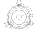
- FIG. 2 is a perspective plan view showing the configuration of the motor according to the present embodiment.
- FIG. 3 is a vertical cross-sectional view of a conventional motor.
- FIG. 4 is a vertical cross-sectional view of the motor of the present embodiment.
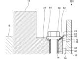
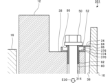
- FIG. 5 is an enlarged partial vertical cross-sectional view of the portion surrounded by the dashed line in FIG.
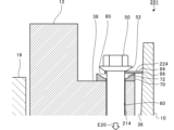
- FIG. 6 is an enlarged partial vertical cross-sectional view of the portion surrounded by the dashed line in FIG.
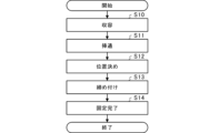
- FIG. 7 is a flowchart illustrating a method for manufacturing a motor according to this embodiment.
- FIG. 8 is a partial vertical cross-sectional view of a motor according to a first modified example.
- FIG. 8 is a partial vertical cross-sectional view of a motor according to a first modified example.
- FIG. 9 is a partial vertical cross-sectional view of a motor according to a first modified example.
- FIG. 10 is a partial vertical cross-sectional view of a motor according to a second modified example.
- FIG. 11 is a partial vertical cross-sectional view of a motor according to a second modified example.
- FIG. 12 is a partial vertical cross-sectional view of a motor according to a third modified example.
- FIG. 13 is a partial vertical cross-sectional view of a motor according to a third modified example.
- FIG. 1 is an exploded perspective view showing the configuration of a motor 1 according to this embodiment.
- FIG. 2 is a perspective plan view showing the configuration of a motor 1 according to this embodiment.
- the motor 1 includes a case 10, a stator 12, a fixed member 14, a rotor 16, a rotating shaft 18, a cover 20, a bearing 22, and a collar member 24.
- the case 10 includes a side portion 30 and a bottom portion 32.
- the side portion 30 is formed in a hollow cylindrical shape.
- the bottom portion 32 is provided at one axial end of the side portion 30, and closes said one end of the side portion 30.
- the side portion 30 and the bottom portion 32 are integrally molded.
- the other axial end of the side portion 30 is open.
- the side surface portion 30 of the case 10 is formed with a case protrusion 34 that protrudes radially outward.
- the case protrusion 34 extends in the axial direction of the side surface portion 30.
- a plurality of case protrusions 34 are formed at equal intervals in the circumferential direction of the side surface portion 30.
- the case protrusions 34 are formed in three locations at 120 degree intervals.
- the stator 12 is formed in a hollow cylindrical shape.
- the outer diameter of the stator 12 is smaller than the inner diameter of the side portion 30 of the case 10.
- the stator 12 is housed in the case 10.
- the outer peripheral surface of the stator 12 is separated from the inner surface 36 of the case 10, i.e., the inner surface of the side portion 30. In other words, the stator 12 is separated from the inner surface of the case 10 in the radial direction of the stator 12.
- the stator 12 is formed with stator protrusions 38 that protrude radially outward.
- the stator protrusions 38 extend in the axial direction of the stator 12.
- the stator protrusions 38 have roughly the same shape as the case protrusions 34.
- a plurality of stator protrusions 38 are formed at equal intervals in the circumferential direction of the stator 12.
- the stator protrusions 38 are formed in the same number and at the same intervals as the case protrusions 34.
- the stator protrusions 38 are formed in three locations at 120 degree intervals.
- the stator 12 is housed in the case 10 with the inner surface of the case protrusions 34 facing the outer surface of the stator protrusions 38.
- the fixing member 14 is formed in a rod shape.
- the fixing member 14 extends in the axial direction of the stator 12.
- the fixing member 14 fixes the stator 12 to the case 10 in the axial direction of the stator 12.
- the fixing member 14 fixes the stator 12 to the bottom surface portion 32 of the case 10.
- the fixing member 14 is disposed at a position on the stator 12 where the stator protrusion 38 is formed.
- a fixing member 14 is provided for each stator protrusion 38.
- the fixing members 14 are disposed at three locations at 120 degree intervals in the circumferential direction of the stator 12. In other words, the stator 12 is fixed to the case 10 by three fixing members 14.
- the rotor 16 is formed in a cylindrical shape.
- the outer diameter of the rotor 16 is smaller than the inner diameter of the stator 12.
- the rotor 16 is housed in the stator 12.
- a predetermined air gap is formed between the rotor 16 and the stator 12. In other words, the outer peripheral surface of the rotor 16 is separated from the inner peripheral surface of the stator 12.
- the rotating shaft 18 is formed in a rod shape.
- the rotating shaft 18 is fitted into the rotor 16 so that the central axis of the rotating shaft 18 and the central axis of the rotor 16 overlap, and is integrated with the rotor 16.
- the central axis of the rotating shaft 18 and the central axis of the rotor 16 correspond to the central axis C1 of the motor 1.
- the cover 20 is attached to the case 10 so as to close the open end of the case 10.
- the bearings 22 are provided between the rotating shaft 18 and the cover 20, and between the rotating shaft 18 and the case 10.
- the bearings 22 support the rotating shaft 18 and the rotor 16 so that they can rotate freely relative to the case 10 and the cover 20.
- stator 12 slots are formed on the inner peripheral surface of the stator 12, and the stator windings are housed in the slots. Magnets are embedded near the outer peripheral surface of the rotor 16. When an alternating current flows through the stator windings, a rotating magnetic field that rotates in the circumferential direction is generated in the stator 12. The rotor 16 rotates in accordance with the rotation of the rotating magnetic field.
- the rotor 16 is supported by the case 10 via bearings 22 so that the central axis of the rotor 16 overlaps the central axis of the case 10. Meanwhile, the stator 12 is fixed to the case 10 via fixing member 14 so that the central axis of the stator 12 overlaps the central axis of the case 10. As a result, the rotor 16 is positioned inside the stator 12 so that the central axis of the rotor 16 overlaps the central axis of the stator 12.
- stator 12 is radially positioned relative to the case 10 during the manufacturing process of the motor 1.
- motor 1 and manufacturing method for the motor 1 of this embodiment which solves the conventional problems.
- FIG. 3 is a vertical cross-sectional view of a conventional motor M.
- the right side of the vertical cross-section of the motor M with respect to the central axis C of the motor M is shown, and the left side of the central axis C is omitted.
- a fitting portion 40 is formed on the case 10 of the conventional motor M.
- the fitting portion 40 is formed on the inner surface of the side portion 30 near the bottom surface portion 32.
- the fitting portion 40 is a portion of the inner surface of the case 10 that has a smaller inner diameter than other portions.
- the inner diameter of the fitting portion 40 is approximately equal to the outer diameter of the stator 12.
- the stator 12 is fitted into the fitting portion 40 of the case 10. In the portion where the stator 12 is fitted into the fitting portion 40, the outer peripheral surface of the stator 12 contacts the inner surface 36 of the case 10.
- the position of the stator 12 relative to the case 10 is determined by fitting the stator 12 into the fitting portion 40 of the case 10.
- stator 12 is fixed to the case 10 in a state where the central axis of the stator 12 is eccentric with respect to the central axis of the case 10 due to molding errors of the fitting portion 40 or other reasons.
- the central axis of the rotor 16 is eccentric with respect to the central axis of the stator 12, and the air gap between the rotor 16 and the stator 12 is biased around the central axis of the stator 12. This creates a strength and weakness in the attractive force between the rotating magnetic field and the magnet around the central axis of the stator 12.
- stator 12 moves closer to the rotor 16 when the attractive force becomes stronger, and moves away from the rotor 16 when the attractive force becomes weaker, causing the stator 12 to vibrate radially with respect to the rotor 16.
- the motor 1 of this embodiment is therefore equipped with a collar member 24 that can assist in the radial positioning of the stator 12 relative to the case 10.
- the stator 12 is positioned using this collar member 24.
- the collar member 24 is not in contact with the inner surface of the case 10.
- FIG. 4 is a vertical cross-sectional view of the motor 1 of this embodiment.
- the right side of the motor 1 in vertical cross-section with respect to the central axis C1 of the motor 1 is shown, and the left side of the central axis C1 is omitted.
- FIG. 4 shows the motor 1 in a state where manufacturing has been completed. As shown in FIG. 4, the motor 1 of this embodiment does not have the mating portion 40 of the conventional motor M.
- Figures 5 and 6 are partial vertical cross-sectional views enlarging the portion surrounded by dashed line D1 in Figure 4.
- Figure 5 shows an example of the stator 12 before it is fixed to the case 10 by the fixing member 14.
- Figure 6 shows an example of the stator 12 after it is fixed to the case 10 by the fixing member 14.
- the state before the stator 12 is fixed to the case 10 by the fixing member 14 may be referred to as the pre-fixing state.
- the state after the stator 12 is fixed to the case 10 by the fixing member 14 may be referred to as the post-fixing state.
- the fixing member 14 is, for example, a bolt.
- a head 50 is formed at one axial end of the fixing member 14.
- the head 50 has a larger outer diameter than the other axial portions of the fixing member 14.
- a seat surface 52 of the head 50 is an inclined surface that is inclined with respect to a plane perpendicular to the central axis of the fixing member 14.
- a thread is formed at the other axial end of the fixing member 14.
- the stator protrusion 38 of the stator 12 has a through hole 60 that passes through the stator 12 in the axial direction.
- the inner diameter of the through hole 60 is smaller than the outer diameter of the head 50 of the fixing member 14, and is larger than the outer diameter of the fixing member 14 other than the head 50. In other words, the fixing member 14 other than the head 50 can be inserted into the through hole 60.
- a screw hole 62 is formed in the bottom surface 32 of the case 10 in the axial direction of the case 10.
- the screw hole 62 screws into the screw of the fixing member 14.
- a pedestal portion 70 is formed at the opening of the through hole 60 in the stator 12.
- the pedestal portion 70 receives the head portion 50 of the fixing member 14.
- the pedestal portion 70 is formed in a circular ring shape.
- the pedestal portion 70 is formed, for example, as a separate member from the stator 12 and is attached to the stator 12.
- the base portion 70 has a slope 72 formed thereon that is inclined with respect to the reference plane.
- the axial height of the outer periphery of the base portion 70 is higher than the axial height of the inner periphery of the base portion 70.
- the slope 72 of the base portion 70 is inclined such that the axial height gradually increases as one moves from the inner periphery of the base portion 70 to the outer periphery.
- the slope 72 of the base portion 70 is inclined at, for example, about 30 degrees with respect to the reference plane. Note that the inclination angle of the slope 72 of the base portion 70 is not limited to the angle shown in the example, and may be set to any angle.
- the slope 72 of the base portion 70 is approximately parallel to the seat surface 52 of the fixing member 14.
- the motor 1 of this embodiment includes a collar member 24.
- the collar member 24 has a ring portion 80, a tube portion 82, and a claw portion 84.
- the annular portion 80 is formed in a circular ring shape.
- the outer diameter of the annular portion 80 is, for example, smaller than the outer diameter of the head 50 of the fixing member 14.
- the inner diameter of the annular portion 80 is smaller than the outer diameter of the head 50 of the fixing member 14 and larger than the outer diameter of the portion of the fixing member 14 other than the head 50.
- the tubular portion 82 is formed in a cylindrical shape. One axial end of the tubular portion 82 is connected to the annular portion 80. The tubular portion 82 extends in the central axial direction of the annular portion 80. The other axial end of the tubular portion 82 is open.
- the outer diameter of the tubular portion 82 is approximately equal to the inner diameter of the through hole 60 of the stator 12.
- the inner diameter of the tubular portion 82 is smaller than the outer diameter of the head 50 of the fixing member 14 and larger than the outer diameter of the portion of the fixing member 14 other than the head 50.
- the parts of the fixing member 14 other than the head 50 can be inserted into the annular portion 80 and the tubular portion 82. Furthermore, the tubular portion 82 can be inserted into the through hole 60 of the stator 12. When the tubular portion 82 is inserted into the through hole 60, the outer peripheral surface of the tubular portion 82 comes into contact with the inner peripheral surface of the through hole 60. In other words, the tubular portion 82 fits into the inner surface of the through hole 60. Furthermore, the tubular portion 82 can slide axially relative to the through hole 60 while being fitted into the inner surface of the through hole 60.
- the claw portion 84 extends from the annular portion 80.
- the annular portion 80, the tube portion 82, and the claw portion 84 are integrally molded.
- the thickness of the claw portion 84 is set to, for example, about 0.5 mm to 1.0 mm. Therefore, the claw portion 84 does not deform when a force for fixing the stator 12 is not applied via the fixing member 14, but becomes deformable when a force for fixing the stator 12 is applied via the fixing member 14.
- the thickness of the claw portion 84 is the dimension of the claw portion 84 in the axial direction of the annular portion 80 in the pre-fixed state.
- the thickness of the claw portion 84 is not limited to the thickness exemplified, and may be any thickness that allows the claw portion 84 to deform.
- the collar member 24 is provided with, for example, two claw portions 84.
- the two claw portions 84 are provided at a predetermined interval in the circumferential direction of the annular portion 80.
- Each claw portion 84 extends from the outer peripheral surface of the annular portion 80 toward the inner surface 36 of the case 10.
- the number of claw portions 84 is not limited to the number shown in the example, and may be one, or three or more.
- the arrangement of the claw portions 84 is not limited to the example, and it is sufficient that they extend at least toward the inner surface 36 of the case 10.
- the claw portion 84 extends in the radial direction of the annular portion 80.
- the claw portion 84 extends along a plane perpendicular to the central axis of the annular portion 80.
- the claw portion 84 is a portion of the outer periphery of the annular portion 80 that protrudes radially outward beyond the other portions.
- the length of the claw portion 84 in the extension direction before fixing is set according to the position where the stator 12 is to be installed relative to the case 10.
- the length of the claw portion 84 before fixing is equal to the distance between the annular portion 80 and the inner surface of the case 10.
- the tip 86 of the claw portion 84 comes into contact with the inner surface 36 of the case 10.
- the tube portion 82 fits into the inner circumferential surface of the through hole 60 and the tip 86 of the claw portion 84 comes into contact with the inner surface 36 of the case 10, so that the radial position of the stator 12 relative to the case 10 can be determined. More specifically, the tube portion 82 fits into the inner surface of the through hole 60, so that the position of the stator 12 relative to the collar member 24 is determined.
- the tip 86 of the claw portion 84 comes into contact with the inner surface 36 of the case 10, so that the position of the collar member 24 relative to the inner surface 36 of the case 10 is determined. As a result, the position of the stator 12 relative to the inner surface 36 of the case 10 is determined via the collar member 24.
- the fixing member 14 can be fastened so as to move in the axial direction, thereby fixing the stator 12 to the case 10 by the fixing member 14. At this time, the fixing member 14 moves in the axial direction, and a force for fixing the stator 12 is applied to the collar member 24 via the fixing member 14. Then, the connection side of the claw portion 84 with the annular portion 80 is pressed in the moving direction of the fixing member 14 by the head 50 of the fixing member 14.
- the height of the outer periphery side of the base portion 70 is higher than the height of the inner periphery side of the base portion 70, the movement of the tip 86 side of the claw portion 84 in the moving direction of the fixing member 14 is restricted by the outer periphery side of the base portion 70. As a result, the claw portion 84 is deformed in the process of fixing the stator 12 to the case 10 by the fixing member 14.
- the claw portion 84 is deformed into a shape that extends along the inclined surface 72 of the base portion 70, as shown in FIG. 6. After fixing, the tip 86 of the claw portion 84 is separated from the inner surface 36 of the case 10, and the claw portion 84 is not in contact with the inner surface 36 of the case 10.
- the claw portion 84 In the pre-fixed state, the claw portion 84 extends in a direction along a plane perpendicular to the central axis of the annular portion 80, and in the post-fixed state, it extends in a direction along the inclined surface 72 of the base portion 70.
- the length of the claw portion 84 in the pre-fixed state is equal to the distance between the annular portion 80 and the inner surface 36 of the case 10. Therefore, even if the claw portion 84 is deformed by the fixing member 14 so that it extends in a direction along the inclined surface 72, the length of the claw portion 84 in the extending direction is substantially equal before and after fixing by the fixing member 14.
- the length of the claw portion 84 in the extending direction i.e., the length of the claw portion 84 in the direction of the inclined surface 72, is equal to the distance between the annular portion 80 and the inner surface 36 of the case 10.
- FIG. 7 is a flowchart explaining the manufacturing method of the motor 1 of this embodiment.
- FIG. 7 shows the steps related to fixing the stator 12 to the case 10, and omits steps that are less relevant to this fixing.
- the worker places the stator 12 in the case 10 so that the central axis of the through hole 60 in the stator 12 roughly overlaps with the central axis of the screw hole 62 in the case 10 (S10).
- the worker inserts the fixing member 14 through the annular portion 80 of the collar member 24 and the through hole 60 of the stator 12 (S11).
- the worker inserts the tubular portion 82 of the collar member 24 into the through hole 60 of the stator 12 and fits the tubular portion 82 into the inner peripheral surface of the through hole 60.
- the worker inserts the fixing member 14 into the annular portion 80.
- the fixing member 14 is also inserted into the tubular portion 82 connected to the annular portion 80.
- the fixing member 14 is inserted into the annular portion 80 from the tip on the side opposite the head 50.
- the tip of the fixing member 14 reaches the screw hole 62 of the case 10.
- the worker fits the tubular portion 82 into the inner surface of the through hole 60, and then inserts the fixing member 14 through the annular portion 80, the tubular portion 82, and the through hole 60.
- the worker brings the tips 86 of the claws 84 of the collar member 24 into contact with the inner surface 36 of the case 10 to determine the position of the stator 12 relative to the case 10 (S12). For example, the worker adjusts the posture of the collar member 24 so that the claws 84 of the collar member 24 with the tubular portion 82 inserted into the through hole 60 extend toward the inner surface 36 of the case 10. The worker then adjusts the radial position of the stator 12 relative to the case 10 so that the tips 86 of all of the claws 84 of the multiple collar members 24 come into contact with the inner surface 36 of the case 10.
- the worker tightens the fixing member 14 so as to move it along the axial direction, thereby deforming the claw portion 84 and fixing the stator 12 to the case 10 (S13).
- the worker sets a tool for rotating the fixing member 14 on the head 50 of the fixing member 14.
- the worker uses the set tool to rotate the fixing member 14 around its axis and screw the screw of the fixing member 14 into the screw hole of the case 10.
- the fixing member 14 moves along the axial direction so that the head 50 approaches the base portion 70.
- the fixing member 14 tightens the case 10 and the stator 12.
- step S13 the worker tightens the head 50 of the fixing member 14 so as to press it against the base portion 70 via the collar member 24.
- the claw portion 84 located between the head 50 and the base portion 70 is pressed against the slope 72 of the base portion 70 by the head 50.
- the positioning and fixing of the stator to the case is performed by a worker.
- the positioning and fixing of the stator to the case may be performed by someone other than a worker, such as a manufacturing robot.
- the manufacturing method of the motor 1 of this embodiment includes the steps of accommodating the stator 12 in the case 10, inserting the rod-shaped fixing member 14 through the annular portion 80 of the collar member 24 having the annular portion 80 and the claw portion 84 and the through hole 60 formed in the stator 12, contacting the tip 86 of the claw portion 84 with the inner surface 36 of the case 10 to determine the position of the stator 12 relative to the case 10, and tightening the fixing member 14 so as to move it along the axial direction, thereby deforming the claw portion 84 and fixing the stator 12 to the case 10.
- the claw portion 84 is not in contact with the inner surface 36 of the case 10.
- the position of the stator 12 relative to the case 10 can be appropriately adjusted by the collar member 24 before fixing.
- the central axis of the case 10 and the central axis of the stator 12 can be appropriately aligned.
- the manufacturing method of the motor 1 of this embodiment after fixing, the outer peripheral surface of the stator 12 is separated from the inner surface of the case 10, and the collar member 24 is not in contact with the inner surface 36 of the case 10. Therefore, even if the stator 12 vibrates in the radial direction, the vibration of the stator 12 is prevented from being transmitted to the inner surface 36 of the case 10. As a result, in the manufacturing method of the motor 1 of this embodiment, even if the central axis of the case 10 and the central axis of the stator 12 are misaligned, it is possible to prevent unnecessary sound from being generated from the case 10.
- the manufacturing method for the motor 1 of this embodiment makes it possible to both align the stator 12 with the case 10 and prevent the emission of unnecessary sound.
- the claws 84 in this embodiment are parts of the outer periphery of the annular portion 80 that protrude radially outward beyond the other parts. Therefore, in the manufacturing method of the motor 1 in this embodiment, the claws 84 can be used to more appropriately position the stator 12 relative to the case 10.
- the head 50 of the fixing member 14 is tightened so as to press it against the base portion 70 via the collar member 24, thereby deforming the claw portion 84 located between the head 50 and the base portion 70.
- the claw portion 84 can be deformed simply by tightening the fixing member 14, and the claw portion 84 can be easily separated from the inner surface 36 of the case 10.
- the claw portion 84 is pressed against the slope 72 by the head 50, so that the claw portion 84 is deformed into a shape that extends along the slope, and the tip 86 of the claw portion 84 moves away from the inner surface 36 of the case 10.
- the claw portion 84 can be more appropriately moved away from the inner surface 36 of the case 10.
- the tube portion 82 fits into the inner circumferential surface of the through hole 60, and the tip 86 of the claw portion 84 comes into contact with the inner surface 36 of the case 10, thereby determining the position of the stator 12 relative to the case 10.
- the positioning of the stator 12 relative to the case 10 can be easily and appropriately performed.
- the stator 12 is spaced apart from the inner surface 36 of the case 10 in the radial direction of the stator 12, the length of the claw portion 84 along its extension direction is equal to the distance between the annular portion 80 and the inner surface 36 of the case 10, and the claw portion 84 does not contact the inner surface 36 of the case.
- the outer peripheral surface and claws 84 of the stator 12 are not in contact with the inner surface 36 of the case 10, so even if the stator 12 vibrates in the radial direction, the vibration of the stator 12 is prevented from being transmitted to the inner surface 36 of the case 10.
- the motor 1 of this embodiment even if the central axis of the case 10 and the central axis of the stator 12 are misaligned, it is possible to prevent unnecessary sound from being generated from the case 10.
- the tip 86 of the claw portion 84 is separated from the inner surface 36 of the case 10, but the length of the claw portion 84 along its extension direction is equal to the distance between the annular portion 80 and the inner surface 36 of the case 10, suggesting that the claw portion 84 was used to radially position the stator 12 relative to the case 10 during the manufacturing process of the motor 1.
- the position of the stator 12 relative to the case 10 can be appropriately adjusted by the claw portion 84 of the collar member 24.
- the motor 1 of this embodiment makes it possible to both align the stator 12 with the case 10 and prevent the emission of unnecessary sound.
- FIGS. 8 and 9 are partial vertical cross-sectional views of the motor 101 of the first modified example.
- FIG. 8 shows the state of the motor 101 of the first modified example before it is fixed.
- FIG. 9 shows the state of the motor 101 of the first modified example after it is fixed.
- the base portion 70 is formed as a separate member from the stator 12, and the base portion 70 is attached to the stator 12.
- the base portion 170 is formed on the stator 12 itself.
- the opening of the through hole 60 of the stator 12 is recessed into the axial side surface of the stator 12 to form the pedestal portion 170.
- the pedestal portion 170 has an inclined surface 172 that is inclined with respect to a reference plane that is a plane perpendicular to the central axis of the through hole 60.
- the claws 84 extend radially from the annular portion 80.
- the tips 86 of the claws 84 come into contact with the inner surface 36 of the case 10, thereby determining the position of the stator 12 relative to the case 10.
- the fixing member 14 is tightened so as to move in the axial direction. Then, as shown in Figure 9, the claw portion 84 between the head 50 of the fixing member 14 and the base portion 170 is pressed against the slope 172 of the base portion 170 by the head 50. This causes the claw portion 84 to deform into a shape that extends along the slope 172 of the base portion 170, and the tip 86 of the claw portion 84 moves away from the inner surface 36 of the case 10.
- the position of the stator 12 relative to the case 10 can be appropriately adjusted by the collar member 24 in the pre-fixed state.
- the outer peripheral surface of the stator 12 is separated from the inner surface 36 of the case 10, and the collar member 24 is not in contact with the inner surface 36 of the case 10.
- the central axis of the case 10 and the central axis of the stator 12 are misaligned, it is possible to prevent unnecessary sound from being generated from the case 10.
- FIGS. 10 and 11 are partial vertical cross-sectional views of the motor 201 of the second modified example.
- FIG. 10 shows the state of the motor 201 of the second modified example before it is fixed.
- FIG. 11 shows the state of the motor 201 of the second modified example after it is fixed.
- the motor 1 of the above embodiment was equipped with a collar member 24 consisting of an annular portion 80, a tubular portion 82, and a claw portion 84.
- the motor 201 of the second modified example is equipped with a collar member 224 instead of the collar member 24 of the above embodiment.
- the collar member 224 of the second modified example does not have a tubular portion 82, and consists of an annular portion 80 and a claw portion 84.
- the motor 201 of the second modified example also includes a fixing member 214 instead of the fixing member 14 of the above embodiment.
- the fixing member 214 of the second modified example has an outer diameter of a rod-shaped portion between the head 50 and the threaded portion that is approximately equal to the inner diameter of the through hole 60 of the stator.
- the rod-shaped portion of the fixing member 214 is adapted to fit into the inner peripheral surface of the through hole 60.
- the fixing member 214 also has an outer diameter of a threaded portion that is equal to or smaller than the outer diameter of the rod-shaped portion.
- the fixing member 214 is, for example, a so-called reamer bolt.
- the inner diameter of the annular portion 80 is approximately equal to the outer diameter of the rod-shaped portion of the fixing member 214.
- the rod-shaped portion of the fixing member 214 is adapted to fit into the inner peripheral surface of the annular portion 80.
- the rod-shaped portion of the fixing member 214 fits into the inner circumferential surface of the through-hole 60, thereby determining the position of the stator 12 relative to the fixing member 214.
- the rod-shaped portion of the fixing member 214 fits into the inner circumferential surface of the annular portion 80, thereby determining the position of the fixing member 214 relative to the collar member 224.
- the tip 86 of the claw portion 84 extending radially outward from the annular portion 80 comes into contact with the inner surface 36 of the case 10, thereby determining the position of the collar member 224 relative to the inner surface 36 of the case 10. That is, in the second modified example, the position of the stator 12 relative to the case 10 can be determined by the fixing member 214 and the collar member 224.
- the fixing member 214 is tightened so as to move in the axial direction. Then, as shown in Figure 11, the claw portion 84 between the head 50 and the base portion 70 of the fixing member 214 is pressed against the slope 72 of the base portion 70 by the head 50. This causes the claw portion 84 to deform into a shape that extends along the slope 72 of the base portion 70, and the tip 86 of the claw portion 84 moves away from the inner surface 36 of the case 10.
- the position of the stator 12 relative to the case 10 can be appropriately adjusted by the fixing member 214 and the collar member 224.
- the outer peripheral surface of the stator 12 in the fixed state, is separated from the inner surface 36 of the case 10, and the collar member 224 is not in contact with the inner surface 36 of the case 10.
- the central axis of the case 10 and the central axis of the stator 12 are misaligned, it is possible to prevent unnecessary sound from being generated from the case 10.
- FIGS. 12 and 13 are partial vertical cross-sectional views of the motor 301 of the third modified example.
- FIG. 12 shows the state of the motor 301 of the third modified example before it is fixed.
- FIG. 13 shows the state of the motor 301 of the third modified example after it is fixed.
- the motor 1 in the above embodiment has a base portion 70 having a slope 72.
- the motor 301 in the third modified example has a base portion 370 instead of the base portion 70 in the above embodiment.
- the base portion 370 of the third modified example has a flat portion 374 that is parallel to a reference plane that is a plane perpendicular to the central axis of the through hole 60, and a protruding portion 376 that protrudes from the flat portion 374.
- the protruding portion 376 is located on the outer peripheral surface side of the base portion 370.
- the flat portion 374 is located on the inner peripheral surface side of the base portion 370.
- the protruding portion 376 is a cylindrical portion that extends along the central axis of the through hole 60.
- the motor 301 of the third modified example is provided with a fixed member 314 instead of the fixed member 14 of the above embodiment.
- the seat surface 52 of the head 50 is a flat surface parallel to the reference plane.
- the inner diameter of the protruding portion 376 of the base portion 370 is larger than the outer diameter of the head 50.
- the claws 84 extend in the radial direction of the annular portion 80.
- the claws 84 are supported by the protruding portion 376 of the base portion 370.
- the tips 86 of the claws 84 come into contact with the inner surface 36 of the case 10, thereby allowing the position of the stator 12 relative to the case 10 to be determined.
- the fixing member 314 is tightened so as to move in the axial direction. Then, as shown in FIG. 13, the claw portion 84 between the head 50 and the base portion 370 of the fixing member 314 is pressed by the head 50 against the flat portion 374 of the base portion 370. Meanwhile, the movement of the tip 86 side of the claw portion 84 in the moving direction of the fixing member 314 is restricted by the protrusion 376 of the base portion 370. As a result, the claw portion 84 is deformed so as to bend near the boundary between the protrusion 376 and the flat portion 374 of the base portion 370, and the tip 86 of the claw portion 84 moves away from the inner surface 36 of the case 10.
- the position of the stator 12 relative to the case 10 can be appropriately adjusted by the collar member 24 in the pre-fixed state.
- the outer peripheral surface of the stator 12 is separated from the inner surface 36 of the case 10, and the collar member 24 is not in contact with the inner surface 36 of the case 10.
- the central axis of the case 10 and the central axis of the stator 12 are misaligned, it is possible to prevent unnecessary sound from being generated from the case 10.
- the threaded portion of the fixing member 14 was screwed into the threaded hole 62 of the case 10.
- the threaded hole 62 of the case 10 may be replaced with a through hole, and the fixing member 14 may be inserted through the through hole of the case 10. Then, the fixing member 14 may be tightened by screwing a nut onto the threaded portion of the fixing member 14 that protrudes outside the case 10.
- the first modified example may be combined with the second modified example to have a configuration having the base portion 170 of the first modified example and the collar member 224 and fixing member 214 of the second modified example. Note that the combinations are not limited to those exemplified.
Landscapes
- Engineering & Computer Science (AREA)
- Power Engineering (AREA)
- Manufacturing & Machinery (AREA)
- Motor Or Generator Frames (AREA)
Priority Applications (4)
| Application Number | Priority Date | Filing Date | Title |
|---|---|---|---|
| PCT/JP2022/037699 WO2024075291A1 (ja) | 2022-10-07 | 2022-10-07 | モータの製造方法、モータ |
| US18/691,673 US20250132649A1 (en) | 2022-10-07 | 2022-10-07 | Method of manufacturing motor and motor |
| CN202280058456.6A CN118160190A (zh) | 2022-10-07 | 2022-10-07 | 电动机的制造方法、电动机 |
| JP2024555598A JPWO2024075291A1 (https=) | 2022-10-07 | 2022-10-07 |
Applications Claiming Priority (1)
| Application Number | Priority Date | Filing Date | Title |
|---|---|---|---|
| PCT/JP2022/037699 WO2024075291A1 (ja) | 2022-10-07 | 2022-10-07 | モータの製造方法、モータ |
Publications (1)
| Publication Number | Publication Date |
|---|---|
| WO2024075291A1 true WO2024075291A1 (ja) | 2024-04-11 |
Family
ID=90607902
Family Applications (1)
| Application Number | Title | Priority Date | Filing Date |
|---|---|---|---|
| PCT/JP2022/037699 Ceased WO2024075291A1 (ja) | 2022-10-07 | 2022-10-07 | モータの製造方法、モータ |
Country Status (4)
| Country | Link |
|---|---|
| US (1) | US20250132649A1 (https=) |
| JP (1) | JPWO2024075291A1 (https=) |
| CN (1) | CN118160190A (https=) |
| WO (1) | WO2024075291A1 (https=) |
Citations (3)
| Publication number | Priority date | Publication date | Assignee | Title |
|---|---|---|---|---|
| JP2013093985A (ja) * | 2011-10-26 | 2013-05-16 | Toyota Motor Corp | ステータ固定構造 |
| JP2016086555A (ja) * | 2014-10-27 | 2016-05-19 | トヨタ自動車株式会社 | 電気機器 |
| JP2020150613A (ja) * | 2019-03-12 | 2020-09-17 | ダイキン工業株式会社 | 圧縮機 |
Family Cites Families (2)
| Publication number | Priority date | Publication date | Assignee | Title |
|---|---|---|---|---|
| US11258316B2 (en) * | 2019-10-04 | 2022-02-22 | Ford Global Technologies, Llc | Stator free end retainer |
| CN113315266A (zh) * | 2021-06-04 | 2021-08-27 | 合肥恒大江海泵业股份有限公司 | 一种电机定子铁芯的叠压斜槽结构 |
-
2022
- 2022-10-07 WO PCT/JP2022/037699 patent/WO2024075291A1/ja not_active Ceased
- 2022-10-07 JP JP2024555598A patent/JPWO2024075291A1/ja active Pending
- 2022-10-07 US US18/691,673 patent/US20250132649A1/en active Pending
- 2022-10-07 CN CN202280058456.6A patent/CN118160190A/zh active Pending
Patent Citations (3)
| Publication number | Priority date | Publication date | Assignee | Title |
|---|---|---|---|---|
| JP2013093985A (ja) * | 2011-10-26 | 2013-05-16 | Toyota Motor Corp | ステータ固定構造 |
| JP2016086555A (ja) * | 2014-10-27 | 2016-05-19 | トヨタ自動車株式会社 | 電気機器 |
| JP2020150613A (ja) * | 2019-03-12 | 2020-09-17 | ダイキン工業株式会社 | 圧縮機 |
Also Published As
| Publication number | Publication date |
|---|---|
| US20250132649A1 (en) | 2025-04-24 |
| CN118160190A (zh) | 2024-06-07 |
| JPWO2024075291A1 (https=) | 2024-04-11 |
Similar Documents
| Publication | Publication Date | Title |
|---|---|---|
| US20070164625A1 (en) | Motor | |
| US11152832B2 (en) | Electric actuator | |
| KR100891602B1 (ko) | 모터 | |
| KR101992818B1 (ko) | 모터 구조 | |
| JP2000116081A (ja) | 電気モ―タを組み立てる方法 | |
| JP2002199666A (ja) | 回転電機及びその製造方法 | |
| CN112425046B (zh) | 电动马达以及带有这种电动马达的泵 | |
| JP2015186326A (ja) | モーター、ロボット、モーターの組み立て方法 | |
| US20240072602A1 (en) | Motor and blower using the same and cartridge for motor | |
| JPWO2014170940A1 (ja) | ハイブリッド車両用回転電機のロータ保持構造 | |
| WO2024075291A1 (ja) | モータの製造方法、モータ | |
| JP6981959B2 (ja) | 電気モータのための磁気ホィール | |
| WO2019003801A1 (ja) | ロータ、およびモータ | |
| JP6168001B2 (ja) | スイッチトリラクタンスモータ | |
| WO2019003800A1 (ja) | ロータ、およびモータ | |
| US12492744B2 (en) | Rotating device | |
| JP4613544B2 (ja) | レゾルバのステータ固定構造 | |
| JP3312694B2 (ja) | ポリゴンミラーの固定方法及びポリゴンスキャナモータ | |
| CN114556751A (zh) | 旋转电机 | |
| JPH11190826A (ja) | 回転多面鏡駆動装置 | |
| CN115800648A (zh) | 用于制造轴向磁通电机的方法、轴向磁通电机和驱动电机单元 | |
| JP2008151527A (ja) | レゾルバロータの取付方法 | |
| JP6647414B2 (ja) | ロボット、モーターユニット、カップリングユニット | |
| JP2022041334A (ja) | センサ固定構造及び方法 | |
| JP2016178815A (ja) | モータの軸受構造及び軸受取付方法 |
Legal Events
| Date | Code | Title | Description |
|---|---|---|---|
| WWE | Wipo information: entry into national phase |
Ref document number: 202280058456.6 Country of ref document: CN |
|
| WWE | Wipo information: entry into national phase |
Ref document number: 18691673 Country of ref document: US |
|
| 121 | Ep: the epo has been informed by wipo that ep was designated in this application |
Ref document number: 22961477 Country of ref document: EP Kind code of ref document: A1 |
|
| WWE | Wipo information: entry into national phase |
Ref document number: 2024555598 Country of ref document: JP |
|
| WWP | Wipo information: published in national office |
Ref document number: 18691673 Country of ref document: US |
|
| NENP | Non-entry into the national phase |
Ref country code: DE |
|
| 122 | Ep: pct application non-entry in european phase |
Ref document number: 22961477 Country of ref document: EP Kind code of ref document: A1 |