WO2024070941A1 - 導線、電線、および導線の製造方法 - Google Patents
導線、電線、および導線の製造方法 Download PDFInfo
- Publication number
- WO2024070941A1 WO2024070941A1 PCT/JP2023/034483 JP2023034483W WO2024070941A1 WO 2024070941 A1 WO2024070941 A1 WO 2024070941A1 JP 2023034483 W JP2023034483 W JP 2023034483W WO 2024070941 A1 WO2024070941 A1 WO 2024070941A1
- Authority
- WO
- WIPO (PCT)
- Prior art keywords
- section
- conductor
- cross
- wire
- less
- Prior art date
- Legal status (The legal status is an assumption and is not a legal conclusion. Google has not performed a legal analysis and makes no representation as to the accuracy of the status listed.)
- Ceased
Links
Images




Classifications
-
- B—PERFORMING OPERATIONS; TRANSPORTING
- B21—MECHANICAL METAL-WORKING WITHOUT ESSENTIALLY REMOVING MATERIAL; PUNCHING METAL
- B21B—ROLLING OF METAL
- B21B1/00—Metal-rolling methods or mills for making semi-finished products of solid or profiled cross-section; Sequence of operations in milling trains; Layout of rolling-mill plant, e.g. grouping of stands; Succession of passes or of sectional pass alternations
- B21B1/16—Metal-rolling methods or mills for making semi-finished products of solid or profiled cross-section; Sequence of operations in milling trains; Layout of rolling-mill plant, e.g. grouping of stands; Succession of passes or of sectional pass alternations for rolling wire rods, bars, merchant bars, rounds wire or material of like small cross-section
-
- B—PERFORMING OPERATIONS; TRANSPORTING
- B21—MECHANICAL METAL-WORKING WITHOUT ESSENTIALLY REMOVING MATERIAL; PUNCHING METAL
- B21C—MANUFACTURE OF METAL SHEETS, WIRE, RODS, TUBES, PROFILES OR LIKE SEMI-MANUFACTURED PRODUCTS OTHERWISE THAN BY ROLLING; AUXILIARY OPERATIONS USED IN CONNECTION WITH METAL-WORKING WITHOUT ESSENTIALLY REMOVING MATERIAL
- B21C1/00—Manufacture of metal sheets, wire, rods, tubes or like semi-manufactured products by drawing
-
- B—PERFORMING OPERATIONS; TRANSPORTING
- B21—MECHANICAL METAL-WORKING WITHOUT ESSENTIALLY REMOVING MATERIAL; PUNCHING METAL
- B21C—MANUFACTURE OF METAL SHEETS, WIRE, RODS, TUBES, PROFILES OR LIKE SEMI-MANUFACTURED PRODUCTS OTHERWISE THAN BY ROLLING; AUXILIARY OPERATIONS USED IN CONNECTION WITH METAL-WORKING WITHOUT ESSENTIALLY REMOVING MATERIAL
- B21C3/00—Profiling tools for metal drawing; Combinations of dies and mandrels for metal drawing
- B21C3/02—Dies; Selection of material therefor; Cleaning thereof
-
- B—PERFORMING OPERATIONS; TRANSPORTING
- B21—MECHANICAL METAL-WORKING WITHOUT ESSENTIALLY REMOVING MATERIAL; PUNCHING METAL
- B21C—MANUFACTURE OF METAL SHEETS, WIRE, RODS, TUBES, PROFILES OR LIKE SEMI-MANUFACTURED PRODUCTS OTHERWISE THAN BY ROLLING; AUXILIARY OPERATIONS USED IN CONNECTION WITH METAL-WORKING WITHOUT ESSENTIALLY REMOVING MATERIAL
- B21C3/00—Profiling tools for metal drawing; Combinations of dies and mandrels for metal drawing
- B21C3/02—Dies; Selection of material therefor; Cleaning thereof
- B21C3/08—Dies; Selection of material therefor; Cleaning thereof with section defined by rollers, balls, or the like
-
- H—ELECTRICITY
- H01—ELECTRIC ELEMENTS
- H01B—CABLES; CONDUCTORS; INSULATORS; SELECTION OF MATERIALS FOR THEIR CONDUCTIVE, INSULATING OR DIELECTRIC PROPERTIES
- H01B5/00—Non-insulated conductors or conductive bodies characterised by their form
- H01B5/02—Single bars, rods, wires, or strips
-
- H—ELECTRICITY
- H01—ELECTRIC ELEMENTS
- H01B—CABLES; CONDUCTORS; INSULATORS; SELECTION OF MATERIALS FOR THEIR CONDUCTIVE, INSULATING OR DIELECTRIC PROPERTIES
- H01B7/00—Insulated conductors or cables characterised by their form
- H01B7/02—Disposition of insulation
Definitions
- a conductor wire with a rectangular cross section is produced by a wire drawing process using multiple dies.
- the metal wire that is the raw material for the conductor wire has a circular cross section.
- the metal wire is gradually processed into a wire rod with an elliptical cross section, and then finished with a finishing die to produce a conductor wire with a rectangular cross section.
- the conductor of the present disclosure is a conductor made of a metal material, and has a rectangular cross section having a width and a thickness, the corners of the rectangular cross section are curved, the ratio S/SV of the area SV of a virtual rectangle circumscribing the rectangular cross section to the area S of the rectangular cross section is 0.975 or more, a first cross section of the conductor is spaced from a second cross section of the conductor along the longitudinal axis of the conductor, a first rate of change based on the width W1 of the first cross section and the width W2 of the second cross section is 0.5% or less, a second rate of change based on the thickness T1 of the first cross section and the thickness T2 of the second cross section is 0.5% or less, the first rate of change is
- FIG. 1 is a schematic diagram of an electric wire according to an embodiment.
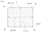
- FIG. 2 is a cross-sectional view of a conductor included in the electric wire shown in FIG.
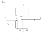
- FIG. 3 is a first explanatory diagram of the method for manufacturing a conductor according to the embodiment.
- FIG. 4 is a second explanatory diagram of the method for manufacturing a conductor according to the embodiment.
- FIG. 5 is a third explanatory diagram of the method for manufacturing a conductor according to the embodiment.
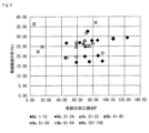
- FIG. 6 is a graph showing the relationship between the corner processing rate P and the cross-sectional area reduction rate for each sample in the test example.
- FIG. 7 is a graph showing the relationship between the ratio S/SV and the arithmetic mean roughness Ra of the corners in each sample of the test example.
- Conductors obtained by wire drawing tend to have rough corner surfaces, which can lead to defects where the insulation layer is insufficiently formed at the rough corners.
- a conductor with a small radius of curvature at the corners is required, but the smaller the radius of curvature at the corners, the more likely the corner surfaces are to become rough and the more likely the number of defects is to increase.
- An insulation layer with many defects may not be able to sufficiently insulate the conductor.
- One of the objects of the present disclosure is to provide a conductor in which defects in the formation of an insulating layer are unlikely to occur at the corners of the rectangular cross section of the conductor.
- One of the objects of the present disclosure is to provide an electric wire in which the insulating layer covering the corners of the rectangular cross section of the conductor has few defects.
- One of the objects of the present disclosure is to provide a manufacturing method for a conductor that can produce the conductor of the present disclosure.
- the conductor of the present disclosure when an insulating layer is formed around the outer periphery of the conductor, suppresses the occurrence of defective portions in the insulating layer covering the corners.
- the conductor according to the embodiment is made of a metal material and has a rectangular cross section having a width and a thickness, the corners of the rectangular cross section are curved, the ratio S/SV of the area SV of a virtual rectangle circumscribing the rectangular cross section to the area S of the rectangular cross section is 0.975 or more, the first cross section of the conductor is separated from the second cross section of the conductor along the longitudinal axis of the conductor, the first rate of change based on the width W1 of the first cross section and the width W2 of the second cross section is 0.5% or less, the second rate of change based on the thickness T1 of the first cross section and the thickness T2 of the second cross section is 0.5% or less, the first rate of change is
- a conductor with an S/SV ratio of 0.975 or more contributes to improving the space factor of the coil.
- Space factor is the ratio of the cross-sectional area of the conductor to the cross-sectional area of the space occupied by the coil when the conductor is wound around it.
- a conductor in which the first rate of change and the second rate of change are both 0.5% or less has a uniform rectangular cross section along the longitudinal axis of the conductor.
- the longitudinal axis of the conductor is an axis line along the conductor connecting the first end and the second end of the conductor.
- the conductor of the present disclosure has small dimensional variation in the direction along the longitudinal axis of the conductor. Products made from this conductor have reduced variation in electrical or magnetic properties. Such a conductor is obtained by wire drawing using a die.
- the arithmetic mean roughness Ra of the surface of the corner is 0.2 ⁇ m or less
- the arithmetic mean roughness Ra of the surface of the parts other than the corner is usually about 0.02 to 0.1 ⁇ m, so the difference in arithmetic mean roughness between the corner and the parts other than the corner can be made small. Therefore, when an insulating layer is formed around the outer periphery of the conductor, defects are unlikely to occur in the insulating layer covering the corner.
- the metal material may be oxygen-free copper.
- Conductors made of oxygen-free copper have excellent electrical conductivity. Oxygen-free copper is easy to process. Conductors made of oxygen-free copper have excellent weldability.
- the area S may be 2 mm2 or more and 12 mm2 or less.
- a conductor wire having an area S of 2 mm2 or more and 12 mm2 or less is suitable as a material for forming a coil.
- the aspect ratio of the rectangular cross section may be 1 or more and 10 or less.
- the aspect ratio is the width of a rectangular cross section divided by the thickness of the rectangular cross section.
- a rectangular cross section with an aspect ratio of 1 is approximately square.
- a conductor with a rectangular cross section whose aspect ratio is greater than 1 is known as a rectangular wire.
- the difference between the width W1 and the width W2, and the difference between the thickness T1 and the thickness T2 may both be 16 ⁇ m or less.
- the conductor ⁇ 5> above has a uniform rectangular cross section along the longitudinal axis of the conductor. Therefore, the conductor ⁇ 5> above suppresses the variation in performance of each turn in the coil made from this conductor. This conductor makes it possible to mass-produce coils that exhibit stable performance.
- the electric wire according to the embodiment comprises a conductor wire described in any one of ⁇ 1> to ⁇ 5> above and an insulating layer covering the surface of the conductor wire.
- An electric wire that has a conductor and an insulating layer can be used, for example, as material for a coil. Because the corners of the conductor are smooth, defects are unlikely to form in the insulating layer that covers the corners. Using such an electric wire, it is possible to create a coil that exhibits stable performance.
- the manufacturing method of the conductor wire includes a step of performing final wire drawing of raw wire material, the raw wire material being a metal wire immediately prior to the final wire drawing step, the cross section of the raw wire material having four corners, the cross section having a width W0, a thickness T0, and a diagonal length L0, the rectangular cross section having a width W, a thickness T, and a diagonal length L, the processing ratio P of the corners in the final wire drawing is 20% or more, the processing ratio P is ⁇ (L0-L)/X ⁇ x 100, where X is the larger of W0-W and T0-T, and the cross-sectional area reduction rate in the final wire drawing is 35% or less.
- the final wiredrawing process is a so-called finishing wiredrawing process. If the cross-sectional area reduction rate in the final wiredrawing process is 35% or less, the conductor is less likely to break. If the cross-sectional area reduction rate is small, the drawing force for pulling the raw wire from the die is smaller, and the stress acting on the raw wire is smaller. However, in a wiredrawing process with a small cross-sectional area reduction rate, the contact area between the die and the raw wire is smaller, and the stress per unit area acting on the surface of the raw wire, i.e., the surface pressure, is rather larger. If the surface pressure acting on the raw wire during drawing is higher, the surface of the conductor, including the corners, tends to become smooth.
- the processing ratio P in the final wiredrawing process is 20% or more, sufficient processing is applied to the corners of the raw wire, and the surface of the corners of the conductor becomes smooth. As a result, a conductor is obtained that has corners with a surface with an arithmetic mean roughness Ra of 0.2 ⁇ m or less.
- the electric wire 1 shown in Fig. 1 includes a conductor 2 made of a metal material and an insulating layer 3 covering the surface of the conductor 2.
- the conductor 2 has a rectangular cross section 20.
- the rectangular cross section 20 is a cross section of the conductor 2 cut along a plane perpendicular to the longitudinal axis of the conductor 2.
- the conductor 2 has a substantially uniform rectangular cross section 20 along the longitudinal axis of the conductor 2.
- the metal material constituting the conductor 2 is, for example, copper, a copper alloy, aluminum, or an aluminum alloy. These metal materials are relatively inexpensive and have excellent conductivity.
- the conductor 2 made of oxygen-free copper has excellent conductivity.
- Oxygen-free copper is pure copper containing 99.95% by mass or more of copper, with the remainder being unavoidable impurities.
- the total content of unavoidable impurities in oxygen-free copper is, for example, 0.03% by mass or less.
- the oxygen content in oxygen-free copper is, for example, 0.005% by mass (50 ppm by mass) or less, further 0.002% by mass (20 ppm by mass) or less, and further 0.001% by mass (10 ppm by mass) or less. The lower the oxygen content in oxygen-free copper, the higher the conductivity of the oxygen-free copper.
- the corners 29 of the rectangular cross section 20 are curved.
- the ratio S/SV of the area SV of the imaginary rectangle 25 circumscribing the rectangular cross section 20 to the area S of the rectangular cross section 20 is 0.975 or more.
- the areas S and SV are obtained from a micrograph of the rectangular cross section 20. Specifically, the micrograph of the rectangular cross section 20 is subjected to image analysis to identify the outer contour of the rectangular cross section 20. The area of the portion surrounded by the outer contour is the area S.
- the imaginary rectangle 25 shown by the two-dot chain line in Figure 2 is the smallest rectangle that circumscribing the outer contour of the rectangular cross section 20 in the micrograph of the rectangular cross section 20. The area inside the imaginary rectangle 25 in the micrograph is the area SV.
- a conductor with a ratio S/SV of 0.975 or more contributes to improving the space factor of the coil.
- the space factor is the ratio of the cross-sectional area of the conductor 2 to the cross-sectional area of the space occupied by the coil in which the conductor 2 is wound.
- the ratio S/SV may be, for example, 0.990 or more, or even 0.995 or more.
- the area S of the rectangular cross section 20 is, for example, 2 mm2 or more and 12 mm2 or less.
- a conductor 2 having an area S of 2 mm2 or more and 12 mm2 or less can be used as a constituent material of a coil.
- the larger the area S the larger the allowable current of the conductor 2.
- the area S may be, for example, 3 mm2 or more and 10 mm2 or less, or 5 mm2 or more and 10 mm2 or less.
- the corner 29 is an arc.
- the radius of curvature of the arc-shaped corner 29 is, for example, 0.07 mm or more and 0.50 mm or less.
- a corner 29 with a radius of curvature of 0.07 mm or more is not easily damaged because it is not too sharp.
- the insulating layer 3 formed on the outer periphery of a corner 29 that is not too sharp is also not easily damaged. If the radius of curvature of the corner 29 is 0.50 mm or less, the area SV of the rectangular cross section 20 does not become too small.
- the radius of curvature may be, for example, 0.09 mm or more and 0.40 mm or less, 0.10 mm or more and 0.25 mm or less, or 0.10 mm or more and 0.15 mm or less.
- the rectangular cross section 20 has a width W and a thickness T.
- the width W of the rectangular cross section 20 is equal to the length of the first side 251 of the imaginary rectangle 25.
- the thickness of the rectangular cross section 20 is equal to the length of the second side 252 perpendicular to the first side 251 of the imaginary rectangle 25.
- the width W and the thickness T may be the same or different. In this example, the width W is longer than the thickness T.
- a conductor 2 having a different width W and thickness T is a so-called rectangular wire.
- first cross section 21 and a second cross section 22 spaced apart along the longitudinal axis of the conductor 2 have almost the same shape and dimensions.
- the first cross section 21 is a rectangular cross section 20 at the position of arrow A in FIG. 1.
- the second cross section 22 is a rectangular cross section 20 at the position of arrow B in FIG. 1.
- the distance between arrows A and B in FIG. 1 is short.
- the distance between the first cross section 21 and the second cross section 22 is, for example, 100 m.
- a first rate of change based on the width W1 of the first cross section 21 and the width W2 of the second cross section 22 is 0.5% (percent) or less
- a second rate of change based on the thickness T1 of the first cross section 21 and the thickness T2 of the second cross section 22 is 0.5% or less.
- a conductor 2 in which the first rate of change and the second rate of change are both 0.5% or less has a substantially uniform rectangular cross section 20 along the longitudinal axis of the conductor 2.
- Wire drawing using a die can produce a conductor 2 with small dimensional variation along the longitudinal axis of the conductor 2. Therefore, it can be said that a conductor 2 in which the first rate of change and the second rate of change are both 0.5% or less has been obtained by wire drawing using a die.
- the first rate of change and the second rate of change may each be 0.4% or less, or 0.2% or less.
- the conductor 2 has a uniform rectangular cross section 20 along the longitudinal axis of the conductor 2, which suppresses the variation in performance of each turn in a coil made with the conductor 2.
- the conductor 2 allows for the mass production of coils that exhibit stable performance.
- the dimensional variation along the longitudinal axis of the conductor 2 may be evaluated in absolute values.
- the difference W1-W2 between the width W1 of the first cross section 21 and the width W2 of the second cross section 22 may be 16 ⁇ m or less
- the difference T1-T2 between the thickness T1 of the first cross section 21 and the thickness T2 of the second cross section 22 may be 16 ⁇ m or less.
- the difference W1-W2 and the difference T1-T2 may be, for example, 12 ⁇ m or less, or 8 ⁇ m or less.
- the surface of the corners 29 of the conductor 2 is very smooth.
- the arithmetic mean roughness Ra of the surface of the corners 29 is 0.2 ⁇ m or less.
- the arithmetic mean roughness Ra is the average of the measurement results measured at three points on each of the four corners 29.
- the arithmetic mean roughness Ra is the average of the measurement results at 12 points.
- the arithmetic mean roughness Ra complies with JIS B 0601:2013.
- the arithmetic mean roughness Ra can be determined, for example, by a commercially available non-contact roughness measuring device, specifically, the LEXT OLS4100 manufactured by Olympus Corporation.
- the surface of the corner 29, which has the arithmetic mean roughness Ra is as smooth as the surface of the parts other than the corner 29. Therefore, when the insulating layer 3 is formed around the outer periphery of the conductor 2, defects are unlikely to occur in the insulating layer 3 covering the corner 29.
- the arithmetic mean roughness Ra may be, for example, 0.15 ⁇ m or less, 0.1 ⁇ m or less, or 0.08 ⁇ m or less.
- the insulating layer 3 ensures insulation of the conductor 2.
- the insulating layer 3 is, for example, enamel formed by solidifying insulating varnish.
- the insulating layer 3 may be a resin having high electrical insulation properties, such as polyimide resin, fluororesin, polyethersulfone, or polyetheretherketone.
- the thickness of the insulating layer 3 may be, for example, 1 ⁇ m or more and 100 ⁇ m or less, or 10 ⁇ m or more and 50 ⁇ m or less.
- the corners 29 of the conductor 2 in this example are very smooth, and defective parts are unlikely to occur in the insulating layer 3 formed on the outer periphery of the smooth corners 29. Therefore, even if the thickness of the insulating layer 3 is within the above range, defective parts are unlikely to occur in the insulating layer 3.
- the insulating layer 3 covers part or all of the surface of the conductor 2.
- the manufacturing method of the electric wire 1 includes a step of obtaining the conductor wire 2 by drawing a metal wire, a step of heat-treating the conductor wire 2, and a step of forming an insulating layer 3 on the outer periphery of the conductor wire 2 after the heat treatment.
- the conductor wire 2 is obtained, for example, by the conductor wire manufacturing method of the present disclosure.
- the conductor wire manufacturing method in this example is performed by a wire drawing device 6 shown in Fig. 3.
- the wire drawing device 6 includes, for example, a plurality of dies 61, 62, 63, and 64. By passing the metal wire 9 through the dies 61, 62, 63, and 64, the metal wire 9 can be gradually brought closer to a desired shape and wire diameter.
- At least the die 64 is a wire drawing die.
- the dies 61, 62, and 63 may be roller dies.
- One of the features of the manufacturing method of the conductor wire 2 is that in the final drawing in the wire drawing device 6, processing is performed under predetermined conditions.
- processing is performed under predetermined conditions.
- the characteristic points of the manufacturing method of the conductor wire 2 will be explained based on Figure 4.
- the metal wire 9 that is fed to the final die 64 will be called the raw wire material 4.
- the solid line in Figure 4 indicates the cross section of the raw wire 4.
- the two-dot chain line indicates the cross section of the conductor 2 obtained by drawing the raw wire 4. Hatching has been omitted in Figure 4 for ease of explanation.
- the raw wire 4 has a cross section 40 having four corners 49.
- the cross section 40 is a cross section of the raw wire 4 cut by a plane perpendicular to the longitudinal axis of the raw wire 4.
- the cross section 40 has a shape that is symmetrical both vertically and horizontally.
- the corners 49 may be sharply pointed, formed by connecting two straight lines, or may be curved.
- the corners 49 in this example are curved.
- the contour line connecting the two adjacent corners 49 along the outer periphery of the cross section may be a straight line, or may be a curved line that is convex in a direction away from the center of the cross section. In this example, the contour line is a straight line.
- the cross section 40 has a width W0 and a thickness T0.
- the width W0 and thickness T0 are equal to the lengths of the first and second sides, respectively, of an imaginary rectangle circumscribing the cross section 40.
- the first and second sides are two sides that are perpendicular to each other.
- the width W0 and thickness T0 may be the same or different. In this example, the width W0 is longer than the thickness T0.
- Corner portions 49 are, for example, portions from both ends of the first side that correspond to 10% of the total length of the first side. Corner portions 49 are, for example, portions from both ends of the second side that correspond to 10% of the total length of the second side.
- the manufacturing method of the conductor 2 includes a step of drawing the raw wire material 4 to obtain the conductor 2 having a rectangular cross section 20.
- the rectangular cross section 20 has a width W and a thickness T.
- the outline of the rectangular cross section 20 in FIG. 4 can be considered to be approximately the same as the outline of the portion of the die hole of the die 64 (FIG. 3) that has the smallest inner diameter, i.e., the bearing of the die 64.
- the rectangular cross section 20 has a shape that is symmetrical both vertically and horizontally.
- the cross-sectional area reduction rate in the final wire drawing process is 35% or less. It is more preferable that the cross-sectional area reduction rate is 15% or more and 35% or less.
- the cross-sectional area reduction rate is an index showing how much the area S of the rectangular cross section 20 has become smaller than the area S0 of the cross section 40. Specifically, the cross-sectional area reduction rate is calculated by ⁇ (S0-S)/S0 ⁇ 100. If the cross-sectional area reduction rate in the final wire drawing process is 35% or less, the surface of the corner 29 becomes smooth.
- the die 64 may be an angle type die, a circle type die, or a hybrid die. As shown in FIG.
- the angle type die is a die in which the shape of the approach 641 of the die 64 in the longitudinal section of the die 64 is linear.
- the circle type die is a die in which the shape of the approach is curved.
- the hybrid die is a die in which the approach shape is a combination of a straight line and a curve.
- the approach angle ⁇ of the die 64 may be constant or may be different at different positions on the approach. In order to increase the degree of processing of the surface of the raw wire 4, it is desirable for the approach angle ⁇ to be high.
- the approach 641 is a tapered portion located on the inlet side of the bearing 642, which is a hole inside the die that determines the dimensions of the conductor 2, and has the function of narrowing the outer diameter of the raw wire 4.
- the approach angle ⁇ is the angle formed by the tapered approach 641 in the vertical cross section of the die 64, and is the sum of the angle formed at the top and the angle formed at the bottom with respect to the horizontal direction.
- the processing rate P of the corners 49 in the wire drawing is 20% or more.
- the processing rate P of the corners 49 is an index showing whether the corners 49 are significantly deformed when the raw wire 4 is drawn. Specifically, the processing rate P is calculated by ⁇ (L0-L)/X ⁇ 100.
- L0 Diagonal length of cross section 40 of raw wire 4
- L Diagonal length of rectangular cross section 20 of conductor 2
- X Maximum deformation amount of portions other than corners 49
- the diagonal length L is the length of the diagonal of the rectangular cross section 20, that is, the distance between the first corner 29 and the second corner 29 at diagonal positions in the rectangular cross section 20.
- the diagonal length L0 is the length of the diagonal of the cross section 40.
- the straight line connecting the first intersection point and the second intersection point in the cross section 40 is the diagonal of the cross section 40.
- the first intersection point and the second intersection point are the intersection points between the extension of the diagonal of the rectangular cross section 20 and the contour line of the cross section 40.
- the value obtained by subtracting the diagonal length L from the diagonal length L0 can be regarded as the deformation amount of the corner 49 due to the final wire drawing process.
- the maximum deformation amount X is the larger of W0-W and T0-T.
- the width W and thickness T are approximately the same as the dimensions of the portion of the die hole of the die 64 that has the smallest inner diameter.
- the corners 49 are hardly deformed, and the portions other than the corners 49 are significantly deformed.
- the maximum deformation amount X is significantly larger than the deformation amount L0-L of the corners 49.
- the processing ratio P is 20% or more.
- the corners 49 are sufficiently processed in the same manner as the other parts, and the surface of the corners 29 becomes as smooth as the other parts.
- a conductor 2 is obtained that has corners 29 with a surface having an arithmetic mean roughness Ra of 0.2 ⁇ m or less.
- the larger the processing ratio P the higher the processing degree of the corners 49 and the smoother the surface of the corners 29.
- the processing ratio P may be, for example, 30% or more, 45% or more, or 60% or more.
- the main purpose of the heat treatment performed after the final drawing is to remove the strain introduced into the conductor wire 2 by the drawing process.
- the removal of the strain improves the electrical conductivity and elongation of the conductor wire 2.
- the atmospheric temperature in the heat treatment is, for example, about 100° C. to 550° C., and the holding time is, for example, 0.2 seconds to 10 hours.
- the heat treatment may be performed in a batch furnace or a continuous furnace. This heat treatment is not essential.
- the insulating layer 3 is formed, for example, by a known enameled wire coating facility.
- a first step is performed in which a resin constituting the insulating layer 3 is applied to the surface of the conductor 2
- a second step is performed in which the resin applied to the conductor 2 is solidified in a baking oven.
- the first and second steps are repeated until the insulating layer 3 reaches a desired thickness.
- Each of the first and second steps may be performed once.
- ⁇ Test Example> In the test example, a number of conductors 2 were produced with different cross-sectional area reduction rates in the final wiredrawing process and different processing ratios P of corners 49.
- the die 64 used in the final wiredrawing process to produce each conductor 2 was an angle die or an arc die.
- an insulating layer 3 was formed on the outer periphery of each conductor 2, and defects in the insulating layer 3 were confirmed.
- the wiredrawing conditions and the dimensions of the conductors 2 are shown in Tables 1 and 2.
- the “Die hole dimensions” in the table are the dimensions of the portion of the die hole of the die 64 that has the smallest inner diameter, i.e., the dimensions of the bearing of the die 64.
- the dimensions of the bearing are approximately equal to the dimensions of the rectangular cross section 20 of the conductor 2. Therefore, the "thickness,” “width,” “curvature radius of corners,” and “area” listed in the “Die hole dimensions” column can be considered to be the “thickness T,” “width W,” “curvature radius of corners 29,” and “area S of rectangular cross section 20" in Figure 4, respectively.
- the “aspect ratio” is "width/thickness.”
- the “degree of pre-processing” in the “final wiredrawing conditions” column in the table indicates the amount of processing applied to the metal wire 9 after the last heat treatment and before the final wiredrawing process, expressed as a percentage. Specifically, the "degree of pre-processing” is ⁇ (S9-S0)/S9 ⁇ x 100.
- S9 is the cross-sectional area of the metal wire 9 immediately before it is fed to the wiredrawing device 6, i.e., the cross-sectional area of the metal wire 9 immediately before the die 61.
- S0 is the cross-sectional area of the cross section 40 of the raw wire 4, i.e., the cross-sectional area of the metal wire 9 immediately before the die 64.
- T0-T", "W0-W”, “L0-L”, and “corner processing ratio P" are as explained in the above section [Conductor manufacturing method].
- the "S/SV ratio" in the "Conductor” column in the table is as explained in the above section [Conductor].
- the area S and area SV were determined by image analysis of cross-sectional images of the conductor 2 taken with a VHX-7000 manufactured by Keyence Corporation.
- the "S/SV ratio” in the table is expressed as a percentage.
- "Dimensional uniformity” is the result of evaluating whether the conductor 2 has a uniform rectangular cross-section 20 along the longitudinal axis.
- the evaluation “A” means that the "first rate of change” and the "second rate of change” explained in the section [Conductor] are both 0.5% or less.
- the distance between the first cross-section 21 and the second cross-section 22 for measuring the "first rate of change" and the "second rate of change” was 100 m.
- the "corner Ra” in the table is the arithmetic mean roughness Ra of the surface of the corner 29 of the conductor 2.
- the unit of arithmetic mean roughness is micrometers.
- the arithmetic mean roughness Ra was measured using a LEXT OLS4100 manufactured by Olympus Corporation. Specifically, the arithmetic mean roughness Ra was measured at three locations on each of the four corners 29, and the arithmetic mean roughness Ra was calculated by averaging the 12 measurement results.
- the three measurement locations on each corner 29 are separated from one another along the circular arc of the corner 29. In this example, each measurement location was measured over a length of 258 ⁇ m along the longitudinal axis of the conductor 2.
- the "Defective point occurrence rate" in the table is the number of defective points in the insulating layer 3 in a 100 kg conductor 2.
- the defective points in the insulating layer 3 were measured using a commercially available flaw detector. If the surface of the conductor 2 is rough, defects such as air pockets will occur between the rough part and the insulating layer 3.
- a commercially available flaw detector was installed next to the coating equipment for the insulating layer 3, and the number of defective points was counted immediately after the insulating layer 3 was formed.
- the weight of the conductor 2 is calculated from the specific gravity of the material of the conductor 2, the area S of the rectangular cross section 20, and the feed speed of the conductor 2 in the coating equipment. In this example, of the measured defective points, only the defective points in the parts corresponding to the corners 29 were counted.
- Samples No. 1 to No. 15 are samples that differ mainly in the cross-sectional area reduction rate.
- Die 64 was an angled die with an approach angle of 32°.
- Samples No. 21 to No. 24 are samples that differ mainly in the radius of curvature of the corner 29 of the conductor 2.
- Die 64 was an angled die with an approach angle of 32°.
- Samples No. 31 to No. 33 are samples that differ mainly in the aspect ratio.
- Die 64 was an angled die with an approach angle of 32°.
- Samples No. 41 and No. 42 are samples that differ mainly in the area S of the rectangular cross section 20 of the conductor 2.
- Die 64 was an angled die with an approach angle of 32°.
- the die 64 was an angle-type die having an approach angle of 32°.
- Samples No. 61 to No. 64 are samples with different die 64 configurations.
- the die 64 of Sample No. 61 was an angle-type die having an approach angle of 24°.
- the die 64 of Sample No. 62 was an angle-type die having an approach angle of 16°.
- the die 64 of Sample No. 63 was an arc-type die having an arc-shaped approach with a radius of curvature of 6 mm.
- the die 64 of Sample No. 64 was an arc-type die having an approach with a radius of curvature of 12 mm.
- Samples No. 101 to No. 104 are samples in which the processing ratio P of the corner portion 29 is less than 20% or the cross-sectional area reduction rate is more than 35%.
- the die 64 was an angle-type die having an approach angle of 32°.
- samples No. 1 to No. 64 which have a cross-sectional area reduction rate of 35% or less and a processing rate P of the corner 49 of 20% or more, have smooth corners 29 and the occurrence rate of defective parts was 0.8 or less.
- Samples No. 101 to No. 103 in which the processing ratio P of the corner 49 is less than 20%, have corners 29 with an arithmetic mean roughness Ra of more than 0.2 ⁇ m, and the incidence of defective parts was more than 1.2.
- Sample No. 104 in which the cross-sectional area reduction rate is more than 35%, has corners 29 with an arithmetic mean roughness Ra of more than 0.2 ⁇ m, and the incidence of defective parts was more than 1.0.
- Figure 6 is a graph showing the relationship between the processing rate P of the corner 49 and the cross-sectional area reduction rate for each sample in the test example.
- the horizontal axis is the processing rate P of the corner 49 for each sample.
- the vertical axis is the cross-sectional area reduction rate for each sample.
- samples No. 101 to No. 104 are samples with a high incidence of defective parts.
- the samples in the range excluding samples No. 101 to No. 104 are samples with a low incidence of defective parts. Therefore, when the processing rate P of the corner 49 is in the range of 20% to 140% and the cross-sectional area reduction rate is in the range of 7% to 35%, the incidence of defective parts is considered to be low.
- the processing rate P of the corner 49 is in the range of 20% to 140% and the cross-sectional area reduction rate is in the range of 15% to 35%, the incidence of defective parts is considered to be even lower. It is believed that the occurrence rate of defects is even lower when the processing rate P of the corner portion 49 is in the range of 40% to 140% and the cross-sectional area reduction rate is in the range of 15% to 35%.
- Figure 7 is a graph showing the relationship between the ratio S/SV and the arithmetic mean roughness Ra of the corners in each sample of the test example.
- the horizontal axis is the ratio S/SV of each sample.
- the vertical axis is the arithmetic mean roughness Ra of the corners 29.
- the arithmetic mean roughness Ra of the corners 29 of samples No. 1 to No. 64 which satisfy the cross-sectional area reduction rate and processing ratio P shown in Figure 6, was 0.2 ⁇ m or less. Therefore, it can be said that the manufacturing method of the conductor 2 according to the embodiment is effective in forming corners 29 with a smooth surface.
Landscapes
- Engineering & Computer Science (AREA)
- Mechanical Engineering (AREA)
- Metal Extraction Processes (AREA)
Abstract
Description
伸線加工によって得られた導線では、角部の表面が粗くなり易く、その粗くなった角部の位置で絶縁層の形成が不十分な不良箇所が発生することがあった。例えばコイルの占積率を高めるために、角部の曲率半径が小さい導線が求められているが、角部の曲率半径が小さくなるほど、角部の表面が粗くなり易く、不良箇所の数が多くなり易い。多くの不良箇所を有する絶縁層では、導線を十分に絶縁できないおそれがある。
本開示の導線は、導線の外周に絶縁層を形成したとき、角部を覆う絶縁層に不良箇所が生じることを抑制する。
以下、本開示の実施態様を列記して説明する。
以下、本開示の実施形態に係る導線、その導線の製造方法、およびその導線を含む電線の具体例を図面に基づいて説明する。図中の同一符号は同一または相当部分を示す。各図面が示す部材の大きさは、説明を明確にする目的で表現されており、必ずしも実際の寸法を表すものではない。なお、本発明はこれらの例示に限定されるものではなく、請求の範囲によって示され、請求の範囲と均等の意味および範囲内でのすべての変更が含まれることが意図される。
≪電線≫
図1に示される電線1は、金属材料からなる導線2と、導線2の表面を覆う絶縁層3と、を備える。導線2は、図2に示されるように、矩形状断面20を有する。矩形状断面20は、導線2の長手軸に直交する平面で切断した導線2の断面である。導線2は、導線2の長手軸にほぼ一様な矩形状断面20を有する。
導線2を構成する金属材料は例えば、銅、銅合金、アルミニウム、またはアルミニウム合金である。これらの金属材料は比較的安価で、かつ導電性に優れる。特に、無酸素銅によって構成される導線2は導電性に優れる。無酸素銅は、銅を99.95質量%以上含有し、残部が不可避不純物である純銅である。無酸素銅における不可避不純物の合計含有量は例えば、0.03質量%以下である。無酸素銅における酸素含有量は例えば、0.005質量%(50質量ppm)以下、更に0.002質量%(20質量ppm)以下、更に0.001質量%(10質量ppm)以下である。無酸素銅における酸素含有量が少ないほど、無酸素銅の導電率が高くなる。
第一変化率…|(W1-W2)/W1|×100
第二変化率…|(T1-T2)/T1|×100
絶縁層3は、導線2の絶縁を確保する。絶縁層3は例えば、絶縁ワニスが固化したエナメルである。その他、絶縁層3は例えば、ポリイミド(polyimide)樹脂、フッ素樹脂、ポリエーテルサルフォン(polyethersulfone)、またはポリエーテルエーテルケトン(polyetheretherketone)などの電気絶縁性の高い樹脂でも良い。
電線1の製造方法は、金属線を伸線することで導線2を得る工程と、導線2を熱処理する工程と、熱処理後の導線2の外周に絶縁層3を形成する工程と、を備える。
導線2は例えば、本開示の導線の製造方法によって得られる。本例における導線の製造方法は、図3に示される伸線装置6によって実施される。伸線装置6は、例えば、複数のダイス61,62,63,64を備える。ダイス61,62,63,64に金属線9を挿通させることで金属線9を所望の形状および線径に徐々に近づけることができる。少なくともダイス64は線引きダイスである。ダイス61,62,63はローラダイスでも良い。
L0…原料線材4の断面40の対角長さ
L…導線2の矩形状断面20の対角長さ
X…角部49以外の部分の最大変形量
最終伸線後に行われる熱処理の主目的は、伸線加工によって導線2に導入された歪みの除去である。歪みの除去によって、導線2の導電率および伸びが向上する。熱処理における雰囲気温度は例えば100℃以上550℃以下程度、保持時間は例えば0.2秒以上10時間以下である。熱処理は、バッチ炉によって実施されても良いし、連続炉によって実施されても良い。この熱処理は必須ではない。
絶縁層3は例えば、公知のエナメル線の被覆設備によって形成される。当該被覆設備では、導線2の表面に絶縁層3を構成する樹脂を塗布する第一工程と、焼付炉において導線2に塗布された樹脂を固化させる第二工程とが実施される。第一工程と第二工程は、絶縁層3が所望の厚さに達するまで繰り返される。第一工程と第二工程とはそれぞれ1回ずつであっても良い。
試験例では、最終伸線加工における断面積減少率、および角部49の加工割合Pが異なる複数の導線2を作製した。各導線2の作製に使用された最終伸線加工におけるダイス64は、角度型ダイスまたは円弧型ダイスである。次いで、各導線2の外周に絶縁層3を形成し、その絶縁層3の不良箇所を確認した。伸線加工の条件、および導線2の寸法を表1,2に示す。


2 導線
20 矩形状断面、21 第一断面、22 第二断面
25 仮想矩形、251 第一辺、252 第二辺
29 角部
3 絶縁層
4 原料線材
40 断面
49 角部
6 伸線装置
61,62,63,64 ダイス
641 アプローチ
642 ベアリング
9 金属線
θ アプローチ角
T,T0,T1,T2 厚さ
W,W0,W1,W2 幅
Claims (7)
- 金属材料からなる導線であって、
幅と厚さとを有する矩形状断面を備え、
前記矩形状断面の角部は曲線であり、
前記矩形状断面に外接する仮想矩形の面積SVと、前記矩形状断面の面積Sとの比S/SVが0.975以上であり、
前記導線の第一断面は、前記導線の長手軸に沿って前記導線の第二断面から離隔しており、
前記第一断面の幅W1と前記第二断面の幅W2とに基づく第一変化率は、0.5%以下であり、
前記前記第一断面の厚さT1と前記第二断面の厚さT2とに基づく第二変化率は、0.5%以下であり、
前記第一変化率は、|(W1-W2)/W1|×100であり、
前記第二変化率は、|(T1-T2)/T1|×100であり、
前記角部の表面の算術平均粗さRaが0.2μm以下である、
導線。 - 前記金属材料は無酸素銅である、請求項1に記載の導線。
- 前記面積Sは2mm2以上12mm2以下である、請求項1または請求項2に記載の導線。
- 前記矩形状断面のアスペクト比は1以上10以下である、請求項1から請求項3のいずれか一項に記載の導線。
- 前記幅W1と前記幅W2との差、および前記厚さT1と前記厚さT2との差が共に、16μm以下である、請求項1から請求項4のいずれか一項に記載の導線。
- 請求項1から請求項5のいずれか一項に記載の導線と、
前記導線の表面を覆う絶縁層と、を備える、
電線。 - 矩形状断面を備える導線を得るための導線の製造方法であって、
原料線材を最終伸線加工する工程を備え、
前記原料線材は前記最終伸線加工する工程の直前の金属線であり、
前記原料線材の断面は4つの角部を有し、
前記断面は、幅W0、厚さT0、および対角長さL0を有し、
前記矩形状断面は、幅W、厚さT、および対角長さLを有し、
前記最終伸線加工における前記角部の加工割合Pが20%以上であり、
前記加工割合Pは、{(L0-L)/X}×100であり、Xは、W0-W、およびT0-Tのうち、大きい方の値であり、
前記最終伸線加工における断面積減少率が35%以下である、
導線の製造方法。
Priority Applications (2)
| Application Number | Priority Date | Filing Date | Title |
|---|---|---|---|
| CN202380051808.XA CN119522459A (zh) | 2022-09-30 | 2023-09-22 | 导线、电线、以及导线的制造方法 |
| JP2024549312A JPWO2024070941A1 (ja) | 2022-09-30 | 2023-09-22 |
Applications Claiming Priority (2)
| Application Number | Priority Date | Filing Date | Title |
|---|---|---|---|
| JP2022158710 | 2022-09-30 | ||
| JP2022-158710 | 2022-09-30 |
Publications (1)
| Publication Number | Publication Date |
|---|---|
| WO2024070941A1 true WO2024070941A1 (ja) | 2024-04-04 |
Family
ID=90477778
Family Applications (1)
| Application Number | Title | Priority Date | Filing Date |
|---|---|---|---|
| PCT/JP2023/034483 Ceased WO2024070941A1 (ja) | 2022-09-30 | 2023-09-22 | 導線、電線、および導線の製造方法 |
Country Status (3)
| Country | Link |
|---|---|
| JP (1) | JPWO2024070941A1 (ja) |
| CN (1) | CN119522459A (ja) |
| WO (1) | WO2024070941A1 (ja) |
Citations (4)
| Publication number | Priority date | Publication date | Assignee | Title |
|---|---|---|---|---|
| JP2008305620A (ja) * | 2007-06-06 | 2008-12-18 | Hitachi Cable Ltd | 絶縁電線 |
| JP2009231065A (ja) * | 2008-03-24 | 2009-10-08 | Fujikura Ltd | 錫系めっき平角導体およびフレキシブルフラットケーブル |
| JP2012195212A (ja) * | 2011-03-17 | 2012-10-11 | Mitsubishi Shindoh Co Ltd | コイル用平角絶縁導線素材とその製造方法 |
| JP2013004444A (ja) * | 2011-06-21 | 2013-01-07 | Mitsubishi Cable Ind Ltd | 絶縁平角銅線及びそれを用いたコイル |
-
2023
- 2023-09-22 JP JP2024549312A patent/JPWO2024070941A1/ja active Pending
- 2023-09-22 CN CN202380051808.XA patent/CN119522459A/zh active Pending
- 2023-09-22 WO PCT/JP2023/034483 patent/WO2024070941A1/ja not_active Ceased
Patent Citations (4)
| Publication number | Priority date | Publication date | Assignee | Title |
|---|---|---|---|---|
| JP2008305620A (ja) * | 2007-06-06 | 2008-12-18 | Hitachi Cable Ltd | 絶縁電線 |
| JP2009231065A (ja) * | 2008-03-24 | 2009-10-08 | Fujikura Ltd | 錫系めっき平角導体およびフレキシブルフラットケーブル |
| JP2012195212A (ja) * | 2011-03-17 | 2012-10-11 | Mitsubishi Shindoh Co Ltd | コイル用平角絶縁導線素材とその製造方法 |
| JP2013004444A (ja) * | 2011-06-21 | 2013-01-07 | Mitsubishi Cable Ind Ltd | 絶縁平角銅線及びそれを用いたコイル |
Also Published As
| Publication number | Publication date |
|---|---|
| JPWO2024070941A1 (ja) | 2024-04-04 |
| CN119522459A (zh) | 2025-02-25 |
Similar Documents
| Publication | Publication Date | Title |
|---|---|---|
| KR102301262B1 (ko) | 알루미늄 합금선, 알루미늄 합금 연선, 피복 전선, 및 단자부착 전선 | |
| CN113994439B (zh) | 铜覆钢线、弹簧、绞合线、绝缘电线以及电缆 | |
| US11810687B2 (en) | Aluminum alloy wire, aluminum alloy strand wire, covered electrical wire, and terminal-equipped electrical wire | |
| US20140360756A1 (en) | Electrically insulated wire | |
| KR102361777B1 (ko) | 알루미늄 합금선, 알루미늄 합금 연선, 피복 전선, 및 단자 장착 전선 | |
| KR102361765B1 (ko) | 알루미늄 합금선, 알루미늄 합금 연선, 피복 전선, 및 단자 장착 전선 | |
| WO2024043284A1 (ja) | アルミニウム系線材、アルミニウム系撚線およびアルミニウム系ケーブル | |
| JP5440951B2 (ja) | 平角エナメル線の製造方法、及び平角エナメル線 | |
| CN109906281B (zh) | 铝合金线、铝合金绞合线、包覆电线以及带端子电线 | |
| WO2024070941A1 (ja) | 導線、電線、および導線の製造方法 | |
| JP7011773B2 (ja) | エナメル線およびエナメル線の製造方法 | |
| CN111801744A (zh) | 绝缘扁平导体、线圈及绝缘扁平导体的制造方法 | |
| JP6840347B2 (ja) | アルミニウム合金線の製造方法 | |
| JP7301930B2 (ja) | エナメル線 | |
| JP7054076B2 (ja) | アルミニウム合金線、アルミニウム合金撚線、被覆電線、及び端子付き電線 | |
| JP5889598B2 (ja) | 平角線の製造方法 | |
| JP7773708B1 (ja) | 銅合金線、銅合金撚線、被覆電線、および端子付き電線 | |
| JP7773707B1 (ja) | 銅合金線、銅合金撚線、被覆電線、および端子付き電線 | |
| JP2018032596A (ja) | 絶縁電線およびその製造方法 | |
| RU213535U1 (ru) | Высокопрочный алюминиевый обмоточный провод | |
| JP2025020877A (ja) | 平角絶縁電線の製造方法 | |
| JP6969569B2 (ja) | アルミニウム合金線、アルミニウム合金撚線、被覆電線、及び端子付き電線 | |
| CN117121128A (zh) | 绝缘电线及线束 | |
| WO2025183120A1 (ja) | 銅系導体、撚線導体および電線 | |
| WO2014156026A1 (ja) | 線状導体及びその製造方法 |
Legal Events
| Date | Code | Title | Description |
|---|---|---|---|
| 121 | Ep: the epo has been informed by wipo that ep was designated in this application |
Ref document number: 23872167 Country of ref document: EP Kind code of ref document: A1 |
|
| WWE | Wipo information: entry into national phase |
Ref document number: 202380051808.X Country of ref document: CN |
|
| WWE | Wipo information: entry into national phase |
Ref document number: 2024549312 Country of ref document: JP |
|
| WWP | Wipo information: published in national office |
Ref document number: 202380051808.X Country of ref document: CN |
|
| WWE | Wipo information: entry into national phase |
Ref document number: 2501001309 Country of ref document: TH |
|
| NENP | Non-entry into the national phase |
Ref country code: DE |
|
| 122 | Ep: pct application non-entry in european phase |
Ref document number: 23872167 Country of ref document: EP Kind code of ref document: A1 |