WO2024070631A1 - 反力付与装置 - Google Patents
反力付与装置 Download PDFInfo
- Publication number
- WO2024070631A1 WO2024070631A1 PCT/JP2023/033032 JP2023033032W WO2024070631A1 WO 2024070631 A1 WO2024070631 A1 WO 2024070631A1 JP 2023033032 W JP2023033032 W JP 2023033032W WO 2024070631 A1 WO2024070631 A1 WO 2024070631A1
- Authority
- WO
- WIPO (PCT)
- Prior art keywords
- shaft member
- lever
- reaction force
- reduction gear
- fitting hole
- Prior art date
- Legal status (The legal status is an assumption and is not a legal conclusion. Google has not performed a legal analysis and makes no representation as to the accuracy of the status listed.)
- Ceased
Links
Images




Classifications
-
- B—PERFORMING OPERATIONS; TRANSPORTING
- B60—VEHICLES IN GENERAL
- B60K—ARRANGEMENT OR MOUNTING OF PROPULSION UNITS OR OF TRANSMISSIONS IN VEHICLES; ARRANGEMENT OR MOUNTING OF PLURAL DIVERSE PRIME-MOVERS IN VEHICLES; AUXILIARY DRIVES FOR VEHICLES; INSTRUMENTATION OR DASHBOARDS FOR VEHICLES; ARRANGEMENTS IN CONNECTION WITH COOLING, AIR INTAKE, GAS EXHAUST OR FUEL SUPPLY OF PROPULSION UNITS IN VEHICLES
- B60K26/00—Arrangement or mounting of propulsion-unit control devices in vehicles
- B60K26/02—Arrangement or mounting of propulsion-unit control devices in vehicles of initiating means or elements
- B60K26/021—Arrangement or mounting of propulsion-unit control devices in vehicles of initiating means or elements with means for providing feel, e.g. by changing pedal force characteristics
-
- B—PERFORMING OPERATIONS; TRANSPORTING
- B60—VEHICLES IN GENERAL
- B60K—ARRANGEMENT OR MOUNTING OF PROPULSION UNITS OR OF TRANSMISSIONS IN VEHICLES; ARRANGEMENT OR MOUNTING OF PLURAL DIVERSE PRIME-MOVERS IN VEHICLES; AUXILIARY DRIVES FOR VEHICLES; INSTRUMENTATION OR DASHBOARDS FOR VEHICLES; ARRANGEMENTS IN CONNECTION WITH COOLING, AIR INTAKE, GAS EXHAUST OR FUEL SUPPLY OF PROPULSION UNITS IN VEHICLES
- B60K26/00—Arrangement or mounting of propulsion-unit control devices in vehicles
- B60K26/02—Arrangement or mounting of propulsion-unit control devices in vehicles of initiating means or elements
-
- G—PHYSICS
- G05—CONTROLLING; REGULATING
- G05G—CONTROL DEVICES OR SYSTEMS INSOFAR AS CHARACTERISED BY MECHANICAL FEATURES ONLY
- G05G1/00—Controlling members, e.g. knobs or handles; Assemblies or arrangements thereof; Indicating position of controlling members
- G05G1/30—Controlling members actuated by foot
-
- G—PHYSICS
- G05—CONTROLLING; REGULATING
- G05G—CONTROL DEVICES OR SYSTEMS INSOFAR AS CHARACTERISED BY MECHANICAL FEATURES ONLY
- G05G1/00—Controlling members, e.g. knobs or handles; Assemblies or arrangements thereof; Indicating position of controlling members
- G05G1/30—Controlling members actuated by foot
- G05G1/44—Controlling members actuated by foot pivoting
-
- G—PHYSICS
- G05—CONTROLLING; REGULATING
- G05G—CONTROL DEVICES OR SYSTEMS INSOFAR AS CHARACTERISED BY MECHANICAL FEATURES ONLY
- G05G5/00—Means for preventing, limiting or returning the movements of parts of a control mechanism, e.g. locking controlling member
- G05G5/03—Means for enhancing the operator's awareness of arrival of the controlling member at a command or datum position; Providing feel, e.g. means for creating a counterforce
-
- B—PERFORMING OPERATIONS; TRANSPORTING
- B60—VEHICLES IN GENERAL
- B60K—ARRANGEMENT OR MOUNTING OF PROPULSION UNITS OR OF TRANSMISSIONS IN VEHICLES; ARRANGEMENT OR MOUNTING OF PLURAL DIVERSE PRIME-MOVERS IN VEHICLES; AUXILIARY DRIVES FOR VEHICLES; INSTRUMENTATION OR DASHBOARDS FOR VEHICLES; ARRANGEMENTS IN CONNECTION WITH COOLING, AIR INTAKE, GAS EXHAUST OR FUEL SUPPLY OF PROPULSION UNITS IN VEHICLES
- B60K26/00—Arrangement or mounting of propulsion-unit control devices in vehicles
- B60K26/02—Arrangement or mounting of propulsion-unit control devices in vehicles of initiating means or elements
- B60K26/021—Arrangement or mounting of propulsion-unit control devices in vehicles of initiating means or elements with means for providing feel, e.g. by changing pedal force characteristics
- B60K2026/023—Arrangement or mounting of propulsion-unit control devices in vehicles of initiating means or elements with means for providing feel, e.g. by changing pedal force characteristics with electrical means to generate counter force or torque
Definitions
- This disclosure relates to a reaction force application device.
- the reaction force applying device in Patent Document 1 includes a lever that applies a reaction force to an accelerator pedal against the driver's depressing force.
- the reaction force applying device also includes a reduction gear that reduces the driving force from the actuator, and a shaft member that is connected at one end to the reduction gear and at the other end to the lever.
- reaction force applying device of Patent Document 1 one end of the shaft member and the lever are fastened together by a nut. This means that the reaction force applying device has a large number of components, which can lead to a complex configuration. In addition, there is a risk that the lever will fall off the shaft member if the nut becomes loose.
- the objective of this disclosure is to provide a reaction force application device with a simple configuration.
- the present disclosure relates to a reaction force applying device capable of applying a reaction force against the driver's depression force to a pedal of an accelerator device having a pedal that is depressed by the driver, the reaction force applying device comprising an actuator, a power transmission unit, and a lever.
- the actuator generates a driving force when electricity is passed through it.
- the power transmission unit has a reduction gear that reduces the driving force from the actuator, and a shaft member connected to the reduction gear.
- One end of the lever is connected to the shaft member, and rotates by the driving force from the actuator that has been reduced by the reduction gear, and is capable of applying the reaction force to the pedal or an arm that rotates together with the pedal.
- the reduction gear and lever are crimped to both ends of the shaft member. This reduces the number of components in the reaction force application device and simplifies the configuration.
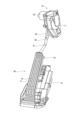
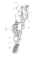
- FIG. 1 is a diagram showing a reaction force application device of a first embodiment and an accelerator device to which the reaction force application device is applied
- FIG. 2 is a perspective view showing a reaction force application device of the first embodiment and an accelerator device to which the reaction force application device is applied
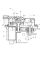
- FIG. 3 is a cross-sectional view showing a reaction force application device of the first embodiment
- FIG. 4 is a cross-sectional view showing a part of the reaction force application device of the first embodiment
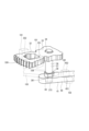
- FIG. 5 is a perspective view showing a state of a crimping and fastening process of members constituting the reaction force application device of the first embodiment
- FIG. 1 is a diagram showing a reaction force application device of a first embodiment and an accelerator device to which the reaction force application device is applied
- FIG. 3 is a cross-sectional view showing a reaction force application device of the first embodiment
- FIG. 4 is a cross-sectional view showing a part of the reaction force application device of the first embodiment
- FIG. 5 is a perspective view showing a
- FIG. 6 is a diagram showing a part of the reaction force application device of the first embodiment
- FIG. 7 is a cross-sectional view showing a state of a crimping and fastening process of members constituting the reaction force application device of the first embodiment
- FIG. 8 is a diagram showing a reaction force application device of a second embodiment and an accelerator device to which the reaction force application device is applied
- FIG. 9 is a perspective view showing a reaction force application device of a second embodiment and an accelerator device to which the reaction force application device is applied
- FIG. 10 is a cross-sectional view showing a part of a reaction force application device according to a third embodiment
- FIG. 11 is a cross-sectional view showing a part of a reaction force application device according to a fourth embodiment
- FIG. 12 is a cross-sectional view showing a part of a reaction force application device according to a fifth embodiment, showing a state before crimping and fastening
- FIG. 13 is a cross-sectional view showing a part of the reaction force application device of the fifth embodiment, showing a state after crimping
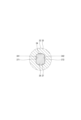
- FIG. 14 is a diagram showing a part of the reaction force application device of the sixth embodiment.
- reaction force application device according to several embodiments and an accelerator device to which the reaction force application device is applied will be described with reference to the drawings. Note that components that are essentially the same in several embodiments will be given the same reference numerals and descriptions will be omitted.
- FIGS. 1-10 A reaction force application device according to a first embodiment and an accelerator device to which the reaction force application device is applied are shown in FIGS.
- the accelerator device 60 is mounted on the vehicle 1 and is used to detect the accelerator opening corresponding to the rotation angle of a pedal 70 depressed by the driver, and to control the driving state of the vehicle 1.
- the accelerator device 60 employs an accelerator-by-wire system and is not mechanically connected to the throttle device of the vehicle 1.
- the accelerator device 60 transmits information relating to the accelerator opening corresponding to the rotation angle of the pedal 70 to an electronic control unit (hereinafter referred to as "ECU"), not shown.
- ECU electronice control unit
- the ECU controls the throttle device based on the accelerator opening transmitted from the accelerator device 60. This controls the driving state of the vehicle 1.
- the reaction force applying device 10 is mounted on the vehicle 1 together with the accelerator device 60, and is capable of applying a reaction force F2 to the pedal 70 of the accelerator device 60 in response to the driver's depression force F1.
- the reaction force applying device 10 is capable of providing the driver with notifications such as danger notices and fuel efficiency improvement notices.
- the reaction force applying device 10 is capable of restricting the rotation of the pedal 70, thereby turning the pedal 70 into a footrest.
- the x-axis indicates the traveling direction of the vehicle 1
- the y-axis indicates the vehicle width direction
- the z-axis indicates the vertical upward direction.
- the following describes the shape or configuration of the accelerator device 60 and the reaction force applying device 10 when attached to the vehicle 1.
- “above” or “upper side” means the upper side or upper side when the accelerator device 60 or the reaction force applying device 10 is attached to the vehicle 1.
- the floor panel 2 has a wall surface 7 that is parallel to the yz plane, and a wall surface 8 that is inclined relative to the wall surface 7.
- the accelerator device 60 includes a pedal housing 61, a pedal 70, etc.
- the pedal housing 61 is attached to the floor panel 2 by being fixed to the wall surface 8 of the floor panel 2 of the vehicle 1, for example, by a mounting bolt (not shown).
- the pedal 70 is rotatably supported by the pedal housing 61 so as to rotate around the rotation axis Ax1.
- the pedal 70 is provided with a pad 71 that is depressed by the driver.
- An accelerator opening sensor (not shown) is provided inside the pedal housing 61. The accelerator opening sensor detects the accelerator opening corresponding to the rotation angle of the pedal 70 that rotates when the driver depresses it, and transmits it to the ECU.
- the rotation axis Ax1 is set to be perpendicular to the z-axis and x-axis, and parallel to the y-axis.
- a pedal biasing member (not shown) is provided inside the pedal housing 61.
- the pedal 70 is biased in the accelerator closing direction by the pedal biasing member.
- the pedal housing 61 has a stopper that restricts rotation of the pedal 70 in the accelerator closing direction, and a stopper that restricts rotation in the accelerator opening direction.
- the pedal 70 can rotate within a range in which it abuts against both stoppers.
- Figure 1 shows the state in which the pedal 70 abuts against the stopper in the accelerator closing direction, i.e., the accelerator is fully closed.
- the reaction force applying device 10 comprises an actuator 20, a power transmission unit 30, and a lever 40.
- the actuator 20 generates a driving force when electricity is applied.
- the power transmission unit 30 has a reduction gear 31 that reduces the driving force from the actuator 20, a reduction gear 32, and a shaft member 36 that is connected to the reduction gear 32.
- One end of the lever 40 is connected to the shaft member 36, and it rotates by the driving force from the actuator 20 that has been reduced by the reduction gears 31 and 32, and can apply a reaction force to the pedal 70 against the driver's depressing force.
- the reduction gear 32 and the lever 40 are crimped and fastened to both ends of the shaft member 36.
- the reaction force applying device 10 includes an actuator housing 11.
- the actuator housing 11 is attached to the floor panel 2 by being fixed to the wall surface 7 of the floor panel 2 of the vehicle 1, for example, by means of mounting bolts (not shown).
- the actuator 20 is, for example, an electric motor, and is housed in the actuator housing 11.
- the actuator 20 is capable of outputting torque as a driving force when electricity is applied to it.
- the ECU controls the application of electricity to the actuator 20, and is capable of controlling the operation of the actuator 20.
- the actuator housing 11 is provided with a power transmission unit 30.
- the power transmission unit 30 is capable of reducing the torque of the actuator 20 and outputting it from a shaft member 36.
- the shaft member 36 is provided on a rotation axis Ax2, and is supported by the actuator housing 11 so as to be rotatable around the rotation axis Ax2.
- the lever 40 has a lever body 41, one lever end 42, the other lever end 43, etc.
- the lever body 41 is formed in a rod shape from, for example, metal, etc.
- the one lever end 42 is connected to one end of the lever body 41 and is formed integrally with the lever body 41.
- the other lever end 43 is connected to the other end of the lever body 41 and is formed integrally with the lever body 41.
- the other lever end 43 is formed so as to be approximately perpendicular to the lever body 41.
- the other lever end 43 is arranged so as to be parallel to the y-axis.
- the lever 40 is provided so that one end 42 of the lever is connected to the shaft member 36.
- the lever 40 is rotatably supported by the actuator housing 11 so as to rotate around the rotation axis Ax2 together with the shaft member 36.
- the lever 40 rotates around the rotation axis Ax2 due to the driving force from the actuator 20 output from the shaft member 36.
- the reaction force applying device 10 is provided so that the outer peripheral wall of the lever other end 43 can abut against the surface of the pedal 70 of the accelerator device 60 on the floor panel 2 side, and can be separated from the surface of the pedal 70 on the floor panel 2 side. In this way, the reaction force applying device 10 can apply a reaction force F2 against the driver's depression force F1 to the pedal 70 from the lever 40, which rotates due to the driving force from the actuator 20.
- reaction force applying device 10 The configuration of the reaction force applying device 10 is described in more detail below.
- the actuator housing 11 has a first housing 12 and a second housing 13.
- the first housing 12 is made of, for example, metal.
- the second housing 13 is made of, for example, resin.
- the first housing 12 and the second housing 13 form a space inside that can accommodate components, etc. by abutting their openings against each other.
- the first housing 12 and the second housing 13 are connected by bolts 14.
- the actuator 20 is provided on the first housing 12 side inside the actuator housing 11.
- the actuator 20 has a shaft 21 and a pinion gear 22.
- One end of the shaft 21 is provided to connect to a rotor (not shown), and is capable of outputting the driving force of the actuator 20.
- the pinion gear 22 is provided at the other end of the shaft 21.
- the pinion gear 22 has external teeth on its outer circumferential wall.
- the reduction gear 31 of the power transmission unit 30 is provided on the second housing 13 side within the actuator housing 11.
- the reduction gear 31 is formed, for example, from resin, and has a large diameter gear 311 and a small diameter gear 312.
- the large diameter gear 311 is formed in an annular shape and has external teeth on its outer circumferential wall.
- the small diameter gear 312 is formed so as to extend in a cylindrical shape from the inner edge of the large diameter gear 311.
- the outer diameter of the small diameter gear 312 is smaller than the outer diameter of the large diameter gear 311. External teeth are formed on the outer circumferential wall of the small diameter gear 312.
- a gear shaft 15 is provided in the first housing 12.
- the gear shaft 15 is supported by the first housing 12 so as to be rotatable about its axis via a bearing 16 provided in the first housing 12.
- the reduction gear 31 is provided on the gear shaft 15 so that the external teeth of the large diameter gear 311 mesh with the external teeth of the pinion gear 22.
- the reduction gear 31 is press-fitted onto the gear shaft 15 so that the inner peripheral wall of the small diameter gear 312 fits into the outer peripheral wall of the gear shaft 15.
- the reduction gear 31 is supported by the first housing 12 so that it can rotate around its axis within the actuator housing 11.
- the reduction gear 32 has a gear fitting hole 34 into which one end of the shaft member 36 fits.
- the lever 40 has a lever fitting hole 44 into which the other end of the shaft member 36 fits.
- the shape of one end of the shaft member 36 and the gear fitting hole 34, and the shape of the other end of the shaft member 36 and the lever fitting hole 44 are non-circular.
- One end of the shaft member 36 and the gear fitting hole 34, and the other end of the shaft member 36 and the lever fitting hole 44 have at least one flat surface at the locations facing each other.
- the reduction gear 32 is provided between the first housing 12 and the second housing 13 inside the actuator housing 11.
- the reduction gear 32 has a gear body 33, a gear fitting hole 34 as a fitting hole, and the like.
- the gear body 33 is formed in a substantially rectangular plate shape, for example, from metal (see Figures 3 and 5).
- External teeth 330 are formed at one end in the longitudinal direction of the gear body 33.
- the gear fitting hole 34 is formed to penetrate the gear body 33 in the plate thickness direction at the end side opposite the external teeth 330 of the gear body 33.
- the shaft member 36 is formed into a rod shape, for example from metal.
- the shaft member 36 is supported by the first housing 12 via a bearing 17 provided in the first housing 12 so as to be rotatable about its axis.
- the reduction gear 32 is mounted on the shaft member 36 so that the external teeth 330 mesh with the external teeth of the small diameter gear 312 of the reduction gear 31.
- the reduction gear 32 is mounted so as not to rotate relative to the shaft member 36 so that the inner wall of the gear fitting hole portion 34 fits into the outer wall of one end of the shaft member 36.
- the lever 40 has a lever fitting hole 44 as a fitting hole.
- the lever one end 42 is formed in a long plate shape.
- the lever fitting hole 44 is formed so as to penetrate the lever one end 42 in the plate thickness direction at the end side of the lever one end 42 opposite the lever body 41.
- the lever 40 is mounted on the shaft member 36 so that the inner wall of the lever fitting hole 44 fits into the outer wall of the other end of the shaft member 36 and is not rotatable relative to the shaft member 36.
- the lever 40 rotates due to the driving force of the actuator 20, and can apply a reaction force F2 to the pedal 70 in response to the driver's depression force F1.
- a spring 18 is provided in the first housing 12 inside the actuator housing 11.
- the spring 18 is, for example, a coil spring, and is provided radially outside the shaft member 36.
- the spring 18 biases the reduction gear 32 or the shaft member 36 so that the lever 40 rotates in a direction in which the other end 43 of the lever abuts against the pedal 70.
- the shaft member 36 has a main shaft portion 37 (see FIG. 7).
- the main shaft portion 37 is formed in a generally cylindrical shape.
- Planes 371 and 372 are formed on one end of the main shaft portion 37 (see FIG. 4 and FIG. 7). Planes 371 and 372 are formed so as to be parallel to each other with the axis of the main shaft portion 37 in between.
- Planes 341 and 342 are formed on the gear fitting hole portion 34 (see FIG. 4 and FIG. 7). Planes 341 and 342 are formed so as to be parallel to each other with the axis of the gear fitting hole portion 34 in between. In this way, one end of the shaft member 36 and the gear fitting hole portion 34 have at least one plane at the portions facing each other.
- One end of the shaft member 36 and the gear fitting hole 34 are fitted together such that planes 371 and 341 face each other, and planes 372 and 342 face each other (see Figures 4 and 7). This restricts the relative rotation between the shaft member 36 and the reduction gear 32.
- the shapes of one end of the shaft member 36 and the gear fitting hole 34 are noncircular.
- the other end of the main shaft portion 37 has flat surfaces 373 and 374 (see Figures 5 and 6).
- Flat surfaces 373 and 374 are formed so as to be parallel to each other with the axis of the main shaft portion 37 in between.
- Flat surfaces 441 and 442 are formed in the lever fitting hole portion 44 (see Figure 6).
- Flat surfaces 441 and 442 are formed so as to be parallel to each other with the axis of the lever fitting hole portion 44 in between. In this way, the other end of the shaft member 36 and the lever fitting hole portion 44 have at least one flat surface in the portion facing each other.
- the cross section of the fitting portion between the shaft member 36 and the reduction gear 32 or the lever 40 is non-circular.
- the fitting portion has at least one flat surface at the portion facing the shaft member 36 and the reduction gear 32 or the lever 40.
- At least one of the reduction gear 32 or the lever 40 has a rotation restriction portion that can restrict the rotation of the reduction gear 32 or the lever 40 by abutting against the jig when a rotational force around the axis acts on the shaft member 36.
- the reduction gear 32 has a rotation restricting portion 351 and a rotation restricting portion 352.
- the rotation restricting portion 351 and the rotation restricting portion 352 are formed on both side surfaces in the plate surface direction at the end portion on the external teeth 330 side of the gear body 33 (see FIG. 5).
- the rotation of the reduction gear 32 can be restricted even if a rotational force around the axis acts on the shaft member 36.
- the lever 40 has a rotation restriction portion 451 and a rotation restriction portion 452.
- the rotation restriction portion 451 and the rotation restriction portion 452 are formed on both side surfaces of the lever one end portion 42 in the plate surface direction (see FIG. 5). By abutting the jig 102 against the rotation restriction portion 451 and the rotation restriction portion 452, the rotation of the lever 40 can be restricted even if a rotational force around the axis acts on the shaft member 36.
- the shaft member 36 has a shaft member rotation restriction portion 38 at a location other than both axial ends, which is capable of restricting the rotation of the shaft member 36 by abutting against a jig when a rotational force around the axis acts on the shaft member 36.
- the shaft member rotation restriction portion 38 is formed to have a D-cut shape.
- shaft member rotation restricting portion 38 is formed in a cylindrical shape so as to protrude radially outward from planes 371 and 372 relative to planes 373 and 374, i.e., from the outer peripheral wall between one end and the other end of main shaft portion 37 (see Figures 5 to 7).
- Plane 381 is formed on a portion of the circumferential direction of the outer peripheral wall of shaft member rotation restricting portion 38.
- shaft member rotation restricting portion 38 is formed in a D-cut shape such that the outer shape is D-shaped when viewed from the axial direction (see Figure 6).
- the shaft member 36 has a seat that abuts against the reduction gear 32 or the lever 40 in the axial direction.
- the reduction gear 32 or the lever 40 has a first plane that abuts against the seat and a second plane that is parallel to the first plane.
- the shaft member 36 has seats 375 and 376.
- the seats 375 are formed in a planar shape on the shaft member rotation restricting portion 38 side of the planes 371 and 372, respectively (see FIG. 7).
- the seats 376 are formed in an annular shape and in a planar shape on the side opposite the seat 375 of the shaft member rotation restricting portion 38, (see FIG. 6 and FIG. 7).
- the reduction gear 32 has a first plane 331 and a second plane 332.
- the first plane 331 is formed in an annular shape around the gear fitting hole 34 on one end face of the gear body 33 so as to abut against the seat surface 375 (see FIG. 7).
- the second plane 332 is formed in an annular shape around the gear fitting hole 34 on the other end face of the gear body 33 so as to be parallel to the first plane 331.
- the lever 40 has a first plane 411 and a second plane 412.
- the first plane 411 is formed in a ring shape around the lever fitting hole 44 on one end face of the lever one end 42 so as to abut against the seat surface 376 (see FIG. 7).
- the second plane 412 is formed in a ring shape around the lever fitting hole 44 on the other end face of the lever one end 42 so as to be parallel to the first plane 411.
- the shaft member 36 has crimped portions 377 and 378.
- the crimped portion 377 is formed by crimping so as to expand radially outward from one end of the main shaft portion 37.
- the crimped portion 377 holds the reduction gear 32 by sandwiching the gear body 33 between itself and the seat surface 375. In this way, by crimping and fastening the reduction gear 32 to one end of the shaft member 36, it is possible to prevent the reduction gear 32 from falling off the shaft member 36.
- the crimping portion 378 is formed by crimping so as to expand radially outward from the other end of the main shaft portion 37.
- the crimping portion 378 holds the lever 40 by sandwiching one end 42 of the lever between itself and the seat 376. In this way, by crimping and fastening the lever 40 to the other end of the shaft member 36, it is possible to prevent the lever 40 from falling off the shaft member 36.
- FIG. 7 shows the lever 40 already crimped and fastened to the shaft member 36.
- the lever 40 and shaft member 36 are positioned so that the crimping portion 378 is positioned in the base recess 111 formed in the base 110, and the second flat surface 412 of the lever 40 abuts against the top surface 112 of the base 110.
- the reduction gear 32 is positioned so that the gear fitting hole portion 34 fits into one end of the shaft member 36.
- the reduction gear 32, lever 40, or shaft member 36 is held by jig 101, jig 102, or jig 103 (see Figure 5).
- the punch 120 is brought into contact with one end of the shaft member 36 and rotated while being pressed toward the base 110. This forms a crimped portion 377 at one end of the shaft member 36, completing the crimping and fastening of the reduction gear 32 to the shaft member 36.
- the crimping portion 378 is located in the base recess 111, and the punch 120 presses the shaft member 36 toward the base 110 with the second flat surface 412 of the lever 40 abutting against the top surface 112 of the base 110, so that the load of the punch 120 acts on the top surface 112 of the base 110 via the seat surface 376, the first flat surface 411, and the second flat surface 412.
- the reduction gear 32 and the shaft member 36 are positioned so that the crimped portion 377 is located in the base recess 111 and the second plane 332 of the reduction gear 32 abuts against the top surface 112 of the base 110, and the punch 120 is abutted against the other end of the shaft member 36 and rotated while being pressed toward the base 110.
- the load of the punch 120 acts on the top surface 112 of the base 110 via the seat surface 375, the first plane 331, and the second plane 332. This makes it possible to prevent the load of the punch 120 from acting on the crimped portion 377.
- the power transmission unit 30 has the reduction gear 31, which reduces the driving force from the actuator 20, the reduction gear 32, and the shaft member 36 connected to the reduction gear 32.
- One end of the lever 40 is connected to the shaft member 36, and it rotates by the driving force from the actuator 20 that has been reduced by the reduction gear 31 and the reduction gear 32, and can apply a reaction force to the pedal 70 against the driver's depressing force.
- the reduction gear 32 and the lever 40 are crimped and fastened to both ends of the shaft member 36.
- the reduction gear 32 has a gear fitting hole 34 into which one end of the shaft member 36 fits.
- the lever 40 has a lever fitting hole 44 into which the other end of the shaft member 36 fits.
- the shape of one end of the shaft member 36 and the gear fitting hole 34, and the shape of the other end of the shaft member 36 and the lever fitting hole 44 are non-circular.
- one end of the shaft member 36 and the gear fitting hole 34, and the other end of the shaft member 36 and the lever fitting hole 44 have at least one flat surface at the location facing each other.
- the relative rotation between the reduction gear 32 and the shaft member 36 can be restricted with a simple configuration.
- the relative rotation between the lever 40 and the shaft member 36 can be restricted with a simple configuration.
- At least one of the reduction gear 32 or the lever 40 has a rotation restriction portion that can restrict the rotation of the reduction gear 32 or the lever 40 by abutting against the jig when a rotational force around the axis acts on the shaft member 36.
- the shaft member 36 has a shaft member rotation restriction portion 38 at a location other than both axial ends, which can restrict the rotation of the shaft member 36 by abutting against a jig when a rotational force around the axis acts on the shaft member 36.
- the shaft member rotation restriction portion 38 is formed to have a D-cut shape.
- the shaft member 36 has a seating surface that abuts against the reduction gear 32 or the lever 40 in the axial direction.
- the reduction gear 32 or the lever 40 has a first plane that abuts against the seating surface and a second plane that is parallel to the first plane.
- Second Embodiment A reaction force application device according to a second embodiment and an accelerator device to which the reaction force application device is applied are shown in Figures 8 and 9.
- the configurations of a reaction force application device 10 and an accelerator device 60 are different from those of the first embodiment.
- the pedal housing 61 of the accelerator device 60 is attached to the floor panel 2 by being fixed to the wall surface 7 of the floor panel 2 of the vehicle 1, for example, by a mounting bolt (not shown).
- the pedal 70 has a pad 71, a pedal base 72, and a pedal connection part 73.
- the pedal connection part 73 is formed, for example, from a metal, and connects the pad 71 and the pedal base 72 such that one end is connected to the pad 71 and the other end is connected to the pedal base 72.
- the pedal base 72 is rotatably supported by the pedal housing 61 so as to rotate around the rotation axis Ax1. This allows the pedal 70 to rotate around the rotation axis Ax1.
- the accelerator device 60 further includes an arm 80.
- the arm 80 is formed, for example, by bending a long metal plate at a predetermined location (see FIG. 9).
- the arm 80 is attached to the pedal 70 with one end connected to the pedal base 72. This allows the arm 80 to rotate around the rotation axis Ax1 together with the pedal 70.
- the actuator housing 11 of the reaction force applying device 10 is attached to the floor panel 2 via the base 9 by being fixed to the base 9 on the wall surface 7 of the floor panel 2 of the vehicle 1, for example, by a mounting bolt (not shown).
- the length of the lever body 41 of the lever 40 in the reaction force applying device 10 is shorter than that in the first embodiment.
- the reaction force applying device 10 is arranged so that the outer peripheral wall of the other end 43 of the lever can abut against the surface of the arm 80 of the accelerator device 60 on the side opposite the floor panel 2, and can be separated from the surface of the arm 80 on the side opposite the floor panel 2.
- the reaction force applying device 10 can apply a reaction force F2 against the driver's depression force F1 to the pedal 70 from the lever 40, which rotates due to the driving force from the actuator 20, via the arm 80.
- This embodiment is similar to the first embodiment except for the configuration described above. Therefore, the same configuration as the first embodiment can achieve the same effects as the first embodiment (same below).
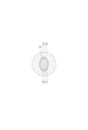
- FIG. 10 A part of a reaction force application device of the third embodiment is shown in Fig. 10.
- the third embodiment differs from the first embodiment in the configurations of a shaft member 36, a reduction gear 32, a lever 40, etc.
- the planes 371, 372, 373, and 374 shown in the first embodiment are not formed on the main shaft portion 37 (see Figures 4 and 10).
- the shape of one end of the main shaft portion 37 is elliptical (see Figure 10).
- the shape of the other end of the main shaft portion 37 is elliptical, similar to the shape of the one end.
- the gear fitting hole 34 does not have the flat surfaces 341 and 342 shown in the first embodiment (see Figs. 4 and 10). In a cross section perpendicular to the axial direction of the shaft member 36, the shape of the gear fitting hole 34 is elliptical (see Fig. 10). The shape of the gear fitting hole 34 corresponds to the shape of one end of the main shaft portion 37.
- One end of the shaft member 36 and the gear fitting hole 34 are fitted together so that the outer peripheral wall of the one end of the shaft member 36 faces the inner peripheral wall of the gear fitting hole 34 (see FIG. 10). This restricts the relative rotation between the shaft member 36 and the reduction gear 32.
- the shapes of the one end of the shaft member 36 and the gear fitting hole 34 are non-circular.
- the lever fitting hole 44 does not have flat surfaces 441 and 442.
- the shape of the lever fitting hole 44 is elliptical.
- the shape of the lever fitting hole 44 corresponds to the shape of the other end of the main shaft 37.
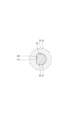
- FIG. 11 A part of a reaction force application device of the fourth embodiment is shown in Fig. 11.
- the fourth embodiment differs from the first embodiment in the configurations of a shaft member 36, a reduction gear 32, a lever 40, etc.
- the planes 372 and 374 shown in the first embodiment are not formed on the main shaft portion 37 (see Figs. 4 and 11).
- one end of the main shaft portion 37 has a D-shape (see Fig. 11).
- the other end of the main shaft portion 37 has a D-shape similar to the shape of the one end.
- the gear fitting hole 34 does not have the flat surface 342 shown in the first embodiment (see Figs. 4 and 11). In a cross section perpendicular to the axial direction of the shaft member 36, the shape of the gear fitting hole 34 is D-shaped (see Fig. 11). The shape of the gear fitting hole 34 corresponds to the shape of one end of the main shaft portion 37.
- the lever fitting hole 44 does not have a flat surface 442.
- the shape of the lever fitting hole 44 is D-shaped.
- the shape of the lever fitting hole 44 corresponds to the shape of the other end of the main shaft 37.
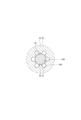
- FIG. 12 A part of a reaction force application device according to a fifth embodiment is shown in Figures 12 and 13.
- the fifth embodiment differs from the first embodiment in the configurations of a shaft member 36, a reduction gear 32, etc.
- the reduction gear 32 has a gear fitting hole 34 into which one end of the shaft member 36 fits.
- the gear fitting hole 34 has a main hole 343 and a hole recess 344 formed to recess radially outward from the main hole 343.
- the shaft member 36 has a main shaft 37 located inside the main hole 343, and a shaft protrusion 379 that protrudes radially outward from the main shaft 37 due to plastic deformation and fits into the hole recess 344.
- six hole recesses 344 are formed at equal intervals around the circumference of the main hole portion 343.
- six shaft protrusions 379 are formed at equal intervals around the circumference of the main shaft portion 37 so as to fit into the hole recesses 344 (see FIG. 13).
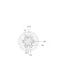
- one end of the main shaft portion 37 is inserted into the gear fitting hole portion 34 (see FIG. 12). At this time, the relative positions of the reduction gear 32 and the shaft member 36 in the rotational direction are adjusted. Next, one end of the shaft member 36 is crimped, which plastically deforms the shaft member 36 and causes the shaft protrusion 379 to protrude radially outward from the main shaft portion 37 and enter the hole recess 344 (see FIG. 13). This completes the crimping fastening of the reduction gear 32 to the shaft member 36.
- the shaft protrusion 379 is formed to fit into the hole recess 344, so the relative rotation between the shaft member 36 and the reduction gear 32 can be reliably restricted.
- the reduction gear 32 has a gear fitting hole 34 into which one end of the shaft member 36 fits.
- the gear fitting hole 34 has a main hole 343 and a hole recess 344 formed to recess radially outward from the main hole 343.
- the shaft member 36 has a main shaft portion 37 located inside the main hole 343, and a shaft protrusion 379 that protrudes radially outward from the main shaft portion 37 due to plastic deformation and fits into the hole recess 344.
- the reduction gear 32 and the shaft member 36 can be crimped and fastened together while adjusting the relative positions of the reduction gear 32 and the shaft member 36 in the rotational direction. Furthermore, after crimping and fastening, the relative rotation between the shaft member 36 and the reduction gear 32 can be reliably restricted.
- FIG. 14 A part of a reaction force application device of the sixth embodiment is shown in Fig. 14.
- the sixth embodiment differs from the first embodiment in the configuration of a shaft member 36.
- the shaft member rotation restriction portion 38 is formed to have a two-sided width shape.
- the shaft member rotation restricting portion 38 further has a flat surface 382.
- the flat surface 382 is formed to be parallel to the flat surface 381 with the axis of the shaft member 36 sandwiched between the flat surface 382 and the flat surface 381.
- the shaft member rotation restricting portion 38 is formed so that its outer shape has a two-sided width shape when viewed from the axial direction (see FIG. 14).
- the rotation of the shaft member 36 can be restricted even if a rotational force around the axis acts on the shaft member 36.
- the wall surface of the floor panel of the vehicle to which the reaction force application device and accelerator device are attached does not have to be formed parallel to the yz plane.
- the wall surface of the floor panel may be formed at any angle relative to the vehicle.
- reaction force application device and accelerator device disclosed herein can also be applied to vehicles other than automobiles.
- a reaction force imparting device for imparting a reaction force to an accelerator pedal (70) that is depressed by a driver, the reaction force imparting device comprising: An actuator (20) that generates a driving force when energized; a power transmission unit (30) having a reduction gear (32) for reducing the speed of a driving force from the actuator and a shaft member (36) connected to the reduction gear; a lever (40) having one end connected to the shaft member, which rotates by a driving force from the actuator reduced in speed by the reduction gear, and capable of applying the reaction force to the pedal or an arm (80) which rotates together with the pedal; The reduction gear and the lever are fastened to both ends of the shaft member by crimping.
- the reduction gear has a gear fitting hole portion (34) into which one end of the shaft member fits,
- the lever has a lever fitting hole (44) into which the other end of the shaft member fits,
- Disclosure 4" At least one of the reduction gear and the lever has a fitting hole portion (34, 44) into which one end or the other end of the shaft member fits,
- the fitting hole portion has a main hole portion (343) and a hole recess portion (344) formed so as to be recessed radially outward from the main hole portion,
- the reaction force imparting device described in Disclosure 1 wherein the shaft member has a main shaft portion (37) located inside the main hole portion, and a shaft protrusion portion (379) that protrudes radially outward from the main shaft portion due to plastic deformation and enters the hole recess.
- Disclosure 7 The reaction force imparting device according to Disclosure 6, wherein the shaft member rotation regulating portion is formed to have a D-cut shape or a two-face width shape.
- Disclosure 8 The shaft member has a seat surface (375, 376) that abuts against the reduction gear or the lever in the axial direction,
Landscapes
- Engineering & Computer Science (AREA)
- Physics & Mathematics (AREA)
- General Physics & Mathematics (AREA)
- Automation & Control Theory (AREA)
- Chemical & Material Sciences (AREA)
- Combustion & Propulsion (AREA)
- Transportation (AREA)
- Mechanical Engineering (AREA)
- Mechanical Control Devices (AREA)
- Auxiliary Drives, Propulsion Controls, And Safety Devices (AREA)
Priority Applications (3)
| Application Number | Priority Date | Filing Date | Title |
|---|---|---|---|
| DE112023004122.9T DE112023004122T5 (de) | 2022-09-30 | 2023-09-11 | Reaktionskraftvermittlungsvorrichtung |
| CN202380052549.2A CN119546473A (zh) | 2022-09-30 | 2023-09-11 | 反作用力赋予装置 |
| US19/027,686 US20250162410A1 (en) | 2022-09-30 | 2025-01-17 | Reaction force imparting device |
Applications Claiming Priority (2)
| Application Number | Priority Date | Filing Date | Title |
|---|---|---|---|
| JP2022159017A JP2024052353A (ja) | 2022-09-30 | 2022-09-30 | 反力付与装置 |
| JP2022-159017 | 2022-09-30 |
Related Child Applications (1)
| Application Number | Title | Priority Date | Filing Date |
|---|---|---|---|
| US19/027,686 Continuation US20250162410A1 (en) | 2022-09-30 | 2025-01-17 | Reaction force imparting device |
Publications (1)
| Publication Number | Publication Date |
|---|---|
| WO2024070631A1 true WO2024070631A1 (ja) | 2024-04-04 |
Family
ID=90477539
Family Applications (1)
| Application Number | Title | Priority Date | Filing Date |
|---|---|---|---|
| PCT/JP2023/033032 Ceased WO2024070631A1 (ja) | 2022-09-30 | 2023-09-11 | 反力付与装置 |
Country Status (5)
| Country | Link |
|---|---|
| US (1) | US20250162410A1 (cg-RX-API-DMAC7.html) |
| JP (1) | JP2024052353A (cg-RX-API-DMAC7.html) |
| CN (1) | CN119546473A (cg-RX-API-DMAC7.html) |
| DE (1) | DE112023004122T5 (cg-RX-API-DMAC7.html) |
| WO (1) | WO2024070631A1 (cg-RX-API-DMAC7.html) |
Cited By (1)
| Publication number | Priority date | Publication date | Assignee | Title |
|---|---|---|---|---|
| US12384243B2 (en) * | 2021-10-21 | 2025-08-12 | Denso Corporation | Reaction force applying device |
Citations (4)
| Publication number | Priority date | Publication date | Assignee | Title |
|---|---|---|---|---|
| JP2001123876A (ja) * | 1999-10-21 | 2001-05-08 | Unisia Jecs Corp | アクセル操作量検出装置 |
| JP2014078174A (ja) * | 2012-10-11 | 2014-05-01 | Honda Motor Co Ltd | 車両用ペダル装置 |
| WO2015049823A1 (ja) * | 2013-10-04 | 2015-04-09 | 本田技研工業株式会社 | アクセルペダル反力制御装置 |
| WO2015053049A1 (ja) * | 2013-10-08 | 2015-04-16 | 株式会社ホンダロック | 反力出力装置 |
Family Cites Families (4)
| Publication number | Priority date | Publication date | Assignee | Title |
|---|---|---|---|---|
| JPH04105727A (ja) * | 1990-08-24 | 1992-04-07 | Delta Kogyo Co Ltd | 軸体の固定構造および固定方法 |
| JP3830228B2 (ja) * | 1997-04-28 | 2006-10-04 | カルソニックカンセイ株式会社 | 電動アクチュエータ |
| JP6361529B2 (ja) * | 2015-03-04 | 2018-07-25 | 株式会社ホンダロック | 反力出力装置 |
| EP3842734B1 (en) * | 2018-08-23 | 2024-05-08 | Mikuni Corporation | Electronically controlled throttle device for engine |
-
2022
- 2022-09-30 JP JP2022159017A patent/JP2024052353A/ja active Pending
-
2023
- 2023-09-11 CN CN202380052549.2A patent/CN119546473A/zh active Pending
- 2023-09-11 WO PCT/JP2023/033032 patent/WO2024070631A1/ja not_active Ceased
- 2023-09-11 DE DE112023004122.9T patent/DE112023004122T5/de active Pending
-
2025
- 2025-01-17 US US19/027,686 patent/US20250162410A1/en active Pending
Patent Citations (4)
| Publication number | Priority date | Publication date | Assignee | Title |
|---|---|---|---|---|
| JP2001123876A (ja) * | 1999-10-21 | 2001-05-08 | Unisia Jecs Corp | アクセル操作量検出装置 |
| JP2014078174A (ja) * | 2012-10-11 | 2014-05-01 | Honda Motor Co Ltd | 車両用ペダル装置 |
| WO2015049823A1 (ja) * | 2013-10-04 | 2015-04-09 | 本田技研工業株式会社 | アクセルペダル反力制御装置 |
| WO2015053049A1 (ja) * | 2013-10-08 | 2015-04-16 | 株式会社ホンダロック | 反力出力装置 |
Cited By (1)
| Publication number | Priority date | Publication date | Assignee | Title |
|---|---|---|---|---|
| US12384243B2 (en) * | 2021-10-21 | 2025-08-12 | Denso Corporation | Reaction force applying device |
Also Published As
| Publication number | Publication date |
|---|---|
| JP2024052353A (ja) | 2024-04-11 |
| US20250162410A1 (en) | 2025-05-22 |
| CN119546473A (zh) | 2025-02-28 |
| DE112023004122T5 (de) | 2025-07-17 |
Similar Documents
| Publication | Publication Date | Title |
|---|---|---|
| US20250162410A1 (en) | Reaction force imparting device | |
| WO2024070632A1 (ja) | 反力付与装置 | |
| US10358031B2 (en) | Reaction force generating apparatus | |
| CN117469322A (zh) | 电子机械制动器、用于其的锁止装置和锁止装置控制方法 | |
| CN111853230B (zh) | 旋转致动器 | |
| US12454921B2 (en) | Throttle device | |
| WO2024070627A1 (ja) | 反力付与装置 | |
| WO2023068336A1 (ja) | 反力付与装置 | |
| JP3081178B2 (ja) | アクセルポジションセンサ | |
| JP5447266B2 (ja) | 電動アクチュエータ | |
| JP7757924B2 (ja) | アクセル装置 | |
| JP4831085B2 (ja) | 内燃機関用の電子式スロットル装置 | |
| US12384243B2 (en) | Reaction force applying device | |
| JP2008195225A (ja) | アクセルペダル装置 | |
| JP7806766B2 (ja) | アクチュエータ、および、それを用いた反力付与装置 | |
| JP2024052353A5 (cg-RX-API-DMAC7.html) | ||
| WO2023068338A1 (ja) | 反力付与装置 | |
| CN115087581A (zh) | 转向装置的制造方法 | |
| JP7826851B2 (ja) | 乗物シート用ギアボックス | |
| JP2007299137A (ja) | ペダル装置 | |
| JP5081060B2 (ja) | 動力伝達装置 | |
| JP4207444B2 (ja) | ペダル振動吸収装置 | |
| JP5966873B2 (ja) | 減速機付きモータ | |
| KR20250007899A (ko) | 액츄에이터 및 이의 제작방법 | |
| WO2024218959A1 (ja) | 回転電機、回転電機の製造方法、ハイブリッド車両用駆動装置、およびハイブリッド車両用駆動装置の製造方法 |
Legal Events
| Date | Code | Title | Description |
|---|---|---|---|
| 121 | Ep: the epo has been informed by wipo that ep was designated in this application |
Ref document number: 23871867 Country of ref document: EP Kind code of ref document: A1 |
|
| WWE | Wipo information: entry into national phase |
Ref document number: 202380052549.2 Country of ref document: CN |
|
| WWP | Wipo information: published in national office |
Ref document number: 202380052549.2 Country of ref document: CN |
|
| WWE | Wipo information: entry into national phase |
Ref document number: 112023004122 Country of ref document: DE |
|
| WWP | Wipo information: published in national office |
Ref document number: 112023004122 Country of ref document: DE |
|
| 122 | Ep: pct application non-entry in european phase |
Ref document number: 23871867 Country of ref document: EP Kind code of ref document: A1 |