WO2024070604A1 - 固体電解コンデンサ及び製造方法 - Google Patents
固体電解コンデンサ及び製造方法 Download PDFInfo
- Publication number
- WO2024070604A1 WO2024070604A1 PCT/JP2023/032913 JP2023032913W WO2024070604A1 WO 2024070604 A1 WO2024070604 A1 WO 2024070604A1 JP 2023032913 W JP2023032913 W JP 2023032913W WO 2024070604 A1 WO2024070604 A1 WO 2024070604A1
- Authority
- WO
- WIPO (PCT)
- Prior art keywords
- conductive polymer
- wound body
- solid electrolytic
- electrolytic capacitor
- acid
- Prior art date
Links
- 239000003990 capacitor Substances 0.000 title claims abstract description 93
- 239000007787 solid Substances 0.000 title claims abstract description 79
- 238000004519 manufacturing process Methods 0.000 title claims abstract description 29
- 229920001940 conductive polymer Polymers 0.000 claims abstract description 181
- 239000011888 foil Substances 0.000 claims abstract description 125
- 239000007788 liquid Substances 0.000 claims abstract description 123
- 239000002390 adhesive tape Substances 0.000 claims abstract description 27
- 230000002209 hydrophobic effect Effects 0.000 claims abstract description 14
- 238000004804 winding Methods 0.000 claims description 29
- 239000003792 electrolyte Substances 0.000 claims description 25
- 239000002904 solvent Substances 0.000 claims description 25
- 239000007784 solid electrolyte Substances 0.000 claims description 20
- WABPQHHGFIMREM-UHFFFAOYSA-N lead(0) Chemical compound [Pb] WABPQHHGFIMREM-UHFFFAOYSA-N 0.000 claims description 19
- XLYOFNOQVPJJNP-UHFFFAOYSA-N water Substances O XLYOFNOQVPJJNP-UHFFFAOYSA-N 0.000 claims description 12
- 238000010294 electrolyte impregnation Methods 0.000 claims description 4
- 238000009835 boiling Methods 0.000 claims description 3
- 238000000034 method Methods 0.000 description 45
- -1 poly(3,4-ethylenedioxythiophene) Polymers 0.000 description 36
- 230000008569 process Effects 0.000 description 29
- 239000010408 film Substances 0.000 description 26
- 239000002253 acid Substances 0.000 description 23
- 239000010410 layer Substances 0.000 description 23
- LYCAIKOWRPUZTN-UHFFFAOYSA-N ethylene glycol Natural products OCCO LYCAIKOWRPUZTN-UHFFFAOYSA-N 0.000 description 22
- 239000000243 solution Substances 0.000 description 22
- 239000000126 substance Substances 0.000 description 21
- 230000015572 biosynthetic process Effects 0.000 description 17
- 238000006243 chemical reaction Methods 0.000 description 17
- 229910052751 metal Inorganic materials 0.000 description 16
- 239000002184 metal Substances 0.000 description 16
- 230000000052 comparative effect Effects 0.000 description 14
- 238000007789 sealing Methods 0.000 description 14
- 238000006116 polymerization reaction Methods 0.000 description 11
- 229920000547 conjugated polymer Polymers 0.000 description 10
- 238000005259 measurement Methods 0.000 description 10
- 229920001609 Poly(3,4-ethylenedioxythiophene) Polymers 0.000 description 9
- 239000001913 cellulose Substances 0.000 description 9
- 229920002678 cellulose Polymers 0.000 description 9
- 239000002019 doping agent Substances 0.000 description 9
- 238000001035 drying Methods 0.000 description 9
- 238000003780 insertion Methods 0.000 description 9
- 230000037431 insertion Effects 0.000 description 9
- 229920005989 resin Polymers 0.000 description 9
- 239000011347 resin Substances 0.000 description 9
- 150000005846 sugar alcohols Polymers 0.000 description 9
- PEDCQBHIVMGVHV-UHFFFAOYSA-N Glycerine Chemical compound OCC(O)CO PEDCQBHIVMGVHV-UHFFFAOYSA-N 0.000 description 8
- NBIIXXVUZAFLBC-UHFFFAOYSA-N Phosphoric acid Chemical compound OP(O)(O)=O NBIIXXVUZAFLBC-UHFFFAOYSA-N 0.000 description 8
- 239000000654 additive Substances 0.000 description 8
- 150000001875 compounds Chemical class 0.000 description 8
- 238000005530 etching Methods 0.000 description 8
- 238000003466 welding Methods 0.000 description 8
- KGBXLFKZBHKPEV-UHFFFAOYSA-N boric acid Chemical compound OB(O)O KGBXLFKZBHKPEV-UHFFFAOYSA-N 0.000 description 7
- 238000010586 diagram Methods 0.000 description 7
- 238000007654 immersion Methods 0.000 description 7
- 150000007522 mineralic acids Chemical class 0.000 description 7
- 150000007524 organic acids Chemical class 0.000 description 7
- 229920000172 poly(styrenesulfonic acid) Polymers 0.000 description 7
- 229940005642 polystyrene sulfonic acid Drugs 0.000 description 7
- 239000000843 powder Substances 0.000 description 7
- 230000008439 repair process Effects 0.000 description 7
- 238000011282 treatment Methods 0.000 description 7
- WEVYAHXRMPXWCK-UHFFFAOYSA-N Acetonitrile Chemical compound CC#N WEVYAHXRMPXWCK-UHFFFAOYSA-N 0.000 description 6
- LFQSCWFLJHTTHZ-UHFFFAOYSA-N Ethanol Chemical compound CCO LFQSCWFLJHTTHZ-UHFFFAOYSA-N 0.000 description 6
- ZMXDDKWLCZADIW-UHFFFAOYSA-N N,N-Dimethylformamide Chemical compound CN(C)C=O ZMXDDKWLCZADIW-UHFFFAOYSA-N 0.000 description 6
- MUBZPKHOEPUJKR-UHFFFAOYSA-N Oxalic acid Chemical compound OC(=O)C(O)=O MUBZPKHOEPUJKR-UHFFFAOYSA-N 0.000 description 6
- WNLRTRBMVRJNCN-UHFFFAOYSA-N adipic acid Chemical compound OC(=O)CCCCC(O)=O WNLRTRBMVRJNCN-UHFFFAOYSA-N 0.000 description 6
- 239000004327 boric acid Substances 0.000 description 6
- 235000010338 boric acid Nutrition 0.000 description 6
- 230000001590 oxidative effect Effects 0.000 description 6
- 230000035699 permeability Effects 0.000 description 6
- 239000002798 polar solvent Substances 0.000 description 6
- 229920000642 polymer Polymers 0.000 description 6
- YMMGRPLNZPTZBS-UHFFFAOYSA-N 2,3-dihydrothieno[2,3-b][1,4]dioxine Chemical class O1CCOC2=C1C=CS2 YMMGRPLNZPTZBS-UHFFFAOYSA-N 0.000 description 5
- GKWLILHTTGWKLQ-UHFFFAOYSA-N 2,3-dihydrothieno[3,4-b][1,4]dioxine Chemical compound O1CCOC2=CSC=C21 GKWLILHTTGWKLQ-UHFFFAOYSA-N 0.000 description 5
- 229910052782 aluminium Inorganic materials 0.000 description 5
- XAGFODPZIPBFFR-UHFFFAOYSA-N aluminium Chemical compound [Al] XAGFODPZIPBFFR-UHFFFAOYSA-N 0.000 description 5
- 239000007864 aqueous solution Substances 0.000 description 5
- 238000005470 impregnation Methods 0.000 description 5
- 239000000178 monomer Substances 0.000 description 5
- DNIAPMSPPWPWGF-UHFFFAOYSA-N monopropylene glycol Natural products CC(O)CO DNIAPMSPPWPWGF-UHFFFAOYSA-N 0.000 description 5
- 150000003839 salts Chemical class 0.000 description 5
- IAZDPXIOMUYVGZ-UHFFFAOYSA-N Dimethylsulphoxide Chemical compound CS(C)=O IAZDPXIOMUYVGZ-UHFFFAOYSA-N 0.000 description 4
- VEXZGXHMUGYJMC-UHFFFAOYSA-N Hydrochloric acid Chemical compound Cl VEXZGXHMUGYJMC-UHFFFAOYSA-N 0.000 description 4
- LRHPLDYGYMQRHN-UHFFFAOYSA-N N-Butanol Chemical compound CCCCO LRHPLDYGYMQRHN-UHFFFAOYSA-N 0.000 description 4
- SECXISVLQFMRJM-UHFFFAOYSA-N N-Methylpyrrolidone Chemical compound CN1CCCC1=O SECXISVLQFMRJM-UHFFFAOYSA-N 0.000 description 4
- 230000000996 additive effect Effects 0.000 description 4
- 150000001298 alcohols Chemical class 0.000 description 4
- 229910000147 aluminium phosphate Inorganic materials 0.000 description 4
- 125000000129 anionic group Chemical group 0.000 description 4
- 238000000151 deposition Methods 0.000 description 4
- 239000006185 dispersion Substances 0.000 description 4
- 150000002170 ethers Chemical class 0.000 description 4
- 239000000835 fiber Substances 0.000 description 4
- 235000011187 glycerol Nutrition 0.000 description 4
- 238000010438 heat treatment Methods 0.000 description 4
- 239000002245 particle Substances 0.000 description 4
- 229920000447 polyanionic polymer Polymers 0.000 description 4
- 125000001424 substituent group Chemical group 0.000 description 4
- 238000007740 vapor deposition Methods 0.000 description 4
- GLDQAMYCGOIJDV-UHFFFAOYSA-N 2,3-dihydroxybenzoic acid Chemical compound OC(=O)C1=CC=CC(O)=C1O GLDQAMYCGOIJDV-UHFFFAOYSA-N 0.000 description 3
- FLDCSPABIQBYKP-UHFFFAOYSA-N 5-chloro-1,2-dimethylbenzimidazole Chemical compound ClC1=CC=C2N(C)C(C)=NC2=C1 FLDCSPABIQBYKP-UHFFFAOYSA-N 0.000 description 3
- QTBSBXVTEAMEQO-UHFFFAOYSA-N Acetic acid Chemical compound CC(O)=O QTBSBXVTEAMEQO-UHFFFAOYSA-N 0.000 description 3
- 239000001741 Ammonium adipate Substances 0.000 description 3
- UHOVQNZJYSORNB-UHFFFAOYSA-N Benzene Chemical compound C1=CC=CC=C1 UHOVQNZJYSORNB-UHFFFAOYSA-N 0.000 description 3
- WVDDGKGOMKODPV-UHFFFAOYSA-N Benzyl alcohol Chemical compound OCC1=CC=CC=C1 WVDDGKGOMKODPV-UHFFFAOYSA-N 0.000 description 3
- LSNNMFCWUKXFEE-UHFFFAOYSA-M Bisulfite Chemical compound OS([O-])=O LSNNMFCWUKXFEE-UHFFFAOYSA-M 0.000 description 3
- OKTJSMMVPCPJKN-UHFFFAOYSA-N Carbon Chemical compound [C] OKTJSMMVPCPJKN-UHFFFAOYSA-N 0.000 description 3
- RTZKZFJDLAIYFH-UHFFFAOYSA-N Diethyl ether Chemical compound CCOCC RTZKZFJDLAIYFH-UHFFFAOYSA-N 0.000 description 3
- XEKOWRVHYACXOJ-UHFFFAOYSA-N Ethyl acetate Chemical compound CCOC(C)=O XEKOWRVHYACXOJ-UHFFFAOYSA-N 0.000 description 3
- OKKJLVBELUTLKV-UHFFFAOYSA-N Methanol Chemical compound OC OKKJLVBELUTLKV-UHFFFAOYSA-N 0.000 description 3
- 239000004743 Polypropylene Substances 0.000 description 3
- OFOBLEOULBTSOW-UHFFFAOYSA-N Propanedioic acid Natural products OC(=O)CC(O)=O OFOBLEOULBTSOW-UHFFFAOYSA-N 0.000 description 3
- HEMHJVSKTPXQMS-UHFFFAOYSA-M Sodium hydroxide Chemical compound [OH-].[Na+] HEMHJVSKTPXQMS-UHFFFAOYSA-M 0.000 description 3
- YTPLMLYBLZKORZ-UHFFFAOYSA-N Thiophene Chemical compound C=1C=CSC=1 YTPLMLYBLZKORZ-UHFFFAOYSA-N 0.000 description 3
- YXFVVABEGXRONW-UHFFFAOYSA-N Toluene Chemical compound CC1=CC=CC=C1 YXFVVABEGXRONW-UHFFFAOYSA-N 0.000 description 3
- ZMANZCXQSJIPKH-UHFFFAOYSA-N Triethylamine Chemical compound CCN(CC)CC ZMANZCXQSJIPKH-UHFFFAOYSA-N 0.000 description 3
- 230000002378 acidificating effect Effects 0.000 description 3
- 230000009471 action Effects 0.000 description 3
- 239000001361 adipic acid Substances 0.000 description 3
- 235000011037 adipic acid Nutrition 0.000 description 3
- 230000032683 aging Effects 0.000 description 3
- 150000001408 amides Chemical class 0.000 description 3
- 235000019293 ammonium adipate Nutrition 0.000 description 3
- JFDZBHWFFUWGJE-UHFFFAOYSA-N benzonitrile Chemical compound N#CC1=CC=CC=C1 JFDZBHWFFUWGJE-UHFFFAOYSA-N 0.000 description 3
- 229910052799 carbon Inorganic materials 0.000 description 3
- KRKNYBCHXYNGOX-UHFFFAOYSA-N citric acid Chemical compound OC(=O)CC(O)(C(O)=O)CC(O)=O KRKNYBCHXYNGOX-UHFFFAOYSA-N 0.000 description 3
- 230000007547 defect Effects 0.000 description 3
- MTHSVFCYNBDYFN-UHFFFAOYSA-N diethylene glycol Chemical compound OCCOCCO MTHSVFCYNBDYFN-UHFFFAOYSA-N 0.000 description 3
- 229910052736 halogen Inorganic materials 0.000 description 3
- 239000000463 material Substances 0.000 description 3
- VLKZOEOYAKHREP-UHFFFAOYSA-N n-Hexane Chemical compound CCCCCC VLKZOEOYAKHREP-UHFFFAOYSA-N 0.000 description 3
- 235000005985 organic acids Nutrition 0.000 description 3
- 239000012466 permeate Substances 0.000 description 3
- 229920001155 polypropylene Polymers 0.000 description 3
- 150000003141 primary amines Chemical class 0.000 description 3
- 150000003335 secondary amines Chemical class 0.000 description 3
- 238000005245 sintering Methods 0.000 description 3
- 229910052715 tantalum Inorganic materials 0.000 description 3
- GUVRBAGPIYLISA-UHFFFAOYSA-N tantalum atom Chemical compound [Ta] GUVRBAGPIYLISA-UHFFFAOYSA-N 0.000 description 3
- 150000003512 tertiary amines Chemical class 0.000 description 3
- IBHWREHFNDMRPR-UHFFFAOYSA-N 2,4,6-Trihydroxybenzoic acid Chemical compound OC(=O)C1=C(O)C=C(O)C=C1O IBHWREHFNDMRPR-UHFFFAOYSA-N 0.000 description 2
- WXTMDXOMEHJXQO-UHFFFAOYSA-N 2,5-dihydroxybenzoic acid Chemical compound OC(=O)C1=CC(O)=CC=C1O WXTMDXOMEHJXQO-UHFFFAOYSA-N 0.000 description 2
- YQUVCSBJEUQKSH-UHFFFAOYSA-N 3,4-dihydroxybenzoic acid Chemical compound OC(=O)C1=CC=C(O)C(O)=C1 YQUVCSBJEUQKSH-UHFFFAOYSA-N 0.000 description 2
- YEJRWHAVMIAJKC-UHFFFAOYSA-N 4-Butyrolactone Chemical compound O=C1CCCO1 YEJRWHAVMIAJKC-UHFFFAOYSA-N 0.000 description 2
- RYGMFSIKBFXOCR-UHFFFAOYSA-N Copper Chemical compound [Cu] RYGMFSIKBFXOCR-UHFFFAOYSA-N 0.000 description 2
- FBPFZTCFMRRESA-FSIIMWSLSA-N D-Glucitol Natural products OC[C@H](O)[C@H](O)[C@@H](O)[C@H](O)CO FBPFZTCFMRRESA-FSIIMWSLSA-N 0.000 description 2
- FBPFZTCFMRRESA-KVTDHHQDSA-N D-Mannitol Chemical compound OC[C@@H](O)[C@@H](O)[C@H](O)[C@H](O)CO FBPFZTCFMRRESA-KVTDHHQDSA-N 0.000 description 2
- FBPFZTCFMRRESA-JGWLITMVSA-N D-glucitol Chemical compound OC[C@H](O)[C@@H](O)[C@H](O)[C@H](O)CO FBPFZTCFMRRESA-JGWLITMVSA-N 0.000 description 2
- ROSDSFDQCJNGOL-UHFFFAOYSA-N Dimethylamine Chemical compound CNC ROSDSFDQCJNGOL-UHFFFAOYSA-N 0.000 description 2
- QUSNBJAOOMFDIB-UHFFFAOYSA-N Ethylamine Chemical compound CCN QUSNBJAOOMFDIB-UHFFFAOYSA-N 0.000 description 2
- KMTRUDSVKNLOMY-UHFFFAOYSA-N Ethylene carbonate Chemical compound O=C1OCCO1 KMTRUDSVKNLOMY-UHFFFAOYSA-N 0.000 description 2
- XEEYBQQBJWHFJM-UHFFFAOYSA-N Iron Chemical compound [Fe] XEEYBQQBJWHFJM-UHFFFAOYSA-N 0.000 description 2
- 229930195725 Mannitol Natural products 0.000 description 2
- AFVFQIVMOAPDHO-UHFFFAOYSA-N Methanesulfonic acid Chemical compound CS(O)(=O)=O AFVFQIVMOAPDHO-UHFFFAOYSA-N 0.000 description 2
- BAVYZALUXZFZLV-UHFFFAOYSA-N Methylamine Chemical compound NC BAVYZALUXZFZLV-UHFFFAOYSA-N 0.000 description 2
- FXHOOIRPVKKKFG-UHFFFAOYSA-N N,N-Dimethylacetamide Chemical compound CN(C)C(C)=O FXHOOIRPVKKKFG-UHFFFAOYSA-N 0.000 description 2
- IMNFDUFMRHMDMM-UHFFFAOYSA-N N-Heptane Chemical compound CCCCCCC IMNFDUFMRHMDMM-UHFFFAOYSA-N 0.000 description 2
- AMQJEAYHLZJPGS-UHFFFAOYSA-N N-Pentanol Chemical compound CCCCCO AMQJEAYHLZJPGS-UHFFFAOYSA-N 0.000 description 2
- PMDCZENCAXMSOU-UHFFFAOYSA-N N-ethylacetamide Chemical compound CCNC(C)=O PMDCZENCAXMSOU-UHFFFAOYSA-N 0.000 description 2
- ATHHXGZTWNVVOU-UHFFFAOYSA-N N-methylformamide Chemical compound CNC=O ATHHXGZTWNVVOU-UHFFFAOYSA-N 0.000 description 2
- GRYLNZFGIOXLOG-UHFFFAOYSA-N Nitric acid Chemical compound O[N+]([O-])=O GRYLNZFGIOXLOG-UHFFFAOYSA-N 0.000 description 2
- 229920002845 Poly(methacrylic acid) Polymers 0.000 description 2
- 239000002202 Polyethylene glycol Substances 0.000 description 2
- BQCADISMDOOEFD-UHFFFAOYSA-N Silver Chemical compound [Ag] BQCADISMDOOEFD-UHFFFAOYSA-N 0.000 description 2
- KKEYFWRCBNTPAC-UHFFFAOYSA-N Terephthalic acid Chemical compound OC(=O)C1=CC=C(C(O)=O)C=C1 KKEYFWRCBNTPAC-UHFFFAOYSA-N 0.000 description 2
- RTAQQCXQSZGOHL-UHFFFAOYSA-N Titanium Chemical compound [Ti] RTAQQCXQSZGOHL-UHFFFAOYSA-N 0.000 description 2
- HCHKCACWOHOZIP-UHFFFAOYSA-N Zinc Chemical compound [Zn] HCHKCACWOHOZIP-UHFFFAOYSA-N 0.000 description 2
- QCWXUUIWCKQGHC-UHFFFAOYSA-N Zirconium Chemical compound [Zr] QCWXUUIWCKQGHC-UHFFFAOYSA-N 0.000 description 2
- 125000000217 alkyl group Chemical group 0.000 description 2
- 125000000909 amidinium group Chemical group 0.000 description 2
- LFVGISIMTYGQHF-UHFFFAOYSA-N ammonium dihydrogen phosphate Chemical compound [NH4+].OP(O)([O-])=O LFVGISIMTYGQHF-UHFFFAOYSA-N 0.000 description 2
- 229910000387 ammonium dihydrogen phosphate Inorganic materials 0.000 description 2
- 150000001450 anions Chemical class 0.000 description 2
- 238000000889 atomisation Methods 0.000 description 2
- 230000004323 axial length Effects 0.000 description 2
- WPYMKLBDIGXBTP-UHFFFAOYSA-N benzoic acid Chemical compound OC(=O)C1=CC=CC=C1 WPYMKLBDIGXBTP-UHFFFAOYSA-N 0.000 description 2
- 239000011230 binding agent Substances 0.000 description 2
- 125000004432 carbon atom Chemical group C* 0.000 description 2
- 150000004649 carbonic acid derivatives Chemical class 0.000 description 2
- 150000001768 cations Chemical class 0.000 description 2
- 230000008859 change Effects 0.000 description 2
- 229910052802 copper Inorganic materials 0.000 description 2
- 239000010949 copper Substances 0.000 description 2
- 150000003950 cyclic amides Chemical class 0.000 description 2
- 230000007423 decrease Effects 0.000 description 2
- 150000001983 dialkylethers Chemical class 0.000 description 2
- AUTNMGCKBXKHNV-UHFFFAOYSA-P diazanium;3,7-dioxido-2,4,6,8,9-pentaoxa-1,3,5,7-tetraborabicyclo[3.3.1]nonane Chemical compound [NH4+].[NH4+].O1B([O-])OB2OB([O-])OB1O2 AUTNMGCKBXKHNV-UHFFFAOYSA-P 0.000 description 2
- JQVDAXLFBXTEQA-UHFFFAOYSA-N dibutylamine Chemical compound CCCCNCCCC JQVDAXLFBXTEQA-UHFFFAOYSA-N 0.000 description 2
- XBDQKXXYIPTUBI-UHFFFAOYSA-N dimethylselenoniopropionate Natural products CCC(O)=O XBDQKXXYIPTUBI-UHFFFAOYSA-N 0.000 description 2
- 238000010894 electron beam technology Methods 0.000 description 2
- 150000002148 esters Chemical class 0.000 description 2
- 238000001704 evaporation Methods 0.000 description 2
- LNTHITQWFMADLM-UHFFFAOYSA-N gallic acid Chemical compound OC(=O)C1=CC(O)=C(O)C(O)=C1 LNTHITQWFMADLM-UHFFFAOYSA-N 0.000 description 2
- 238000009689 gas atomisation Methods 0.000 description 2
- ZTOMUSMDRMJOTH-UHFFFAOYSA-N glutaronitrile Chemical compound N#CCCCC#N ZTOMUSMDRMJOTH-UHFFFAOYSA-N 0.000 description 2
- MNWFXJYAOYHMED-UHFFFAOYSA-N heptanoic acid Chemical compound CCCCCCC(O)=O MNWFXJYAOYHMED-UHFFFAOYSA-N 0.000 description 2
- 150000002391 heterocyclic compounds Chemical class 0.000 description 2
- ZSIAUFGUXNUGDI-UHFFFAOYSA-N hexan-1-ol Chemical compound CCCCCCO ZSIAUFGUXNUGDI-UHFFFAOYSA-N 0.000 description 2
- 229930195733 hydrocarbon Natural products 0.000 description 2
- 150000002430 hydrocarbons Chemical class 0.000 description 2
- 239000012535 impurity Substances 0.000 description 2
- KQNPFQTWMSNSAP-UHFFFAOYSA-N isobutyric acid Chemical compound CC(C)C(O)=O KQNPFQTWMSNSAP-UHFFFAOYSA-N 0.000 description 2
- QQVIHTHCMHWDBS-UHFFFAOYSA-N isophthalic acid Chemical compound OC(=O)C1=CC=CC(C(O)=O)=C1 QQVIHTHCMHWDBS-UHFFFAOYSA-N 0.000 description 2
- 150000002596 lactones Chemical class 0.000 description 2
- 239000000594 mannitol Substances 0.000 description 2
- 235000010355 mannitol Nutrition 0.000 description 2
- 239000002923 metal particle Substances 0.000 description 2
- 150000002739 metals Chemical class 0.000 description 2
- 239000000203 mixture Substances 0.000 description 2
- 235000019837 monoammonium phosphate Nutrition 0.000 description 2
- 229910052758 niobium Inorganic materials 0.000 description 2
- 239000010955 niobium Substances 0.000 description 2
- GUCVJGMIXFAOAE-UHFFFAOYSA-N niobium atom Chemical compound [Nb] GUCVJGMIXFAOAE-UHFFFAOYSA-N 0.000 description 2
- 229910017604 nitric acid Inorganic materials 0.000 description 2
- 150000004767 nitrides Chemical class 0.000 description 2
- 150000002825 nitriles Chemical class 0.000 description 2
- BDJRBEYXGGNYIS-UHFFFAOYSA-N nonanedioic acid Chemical compound OC(=O)CCCCCCCC(O)=O BDJRBEYXGGNYIS-UHFFFAOYSA-N 0.000 description 2
- 239000003960 organic solvent Substances 0.000 description 2
- 235000006408 oxalic acid Nutrition 0.000 description 2
- XNGIFLGASWRNHJ-UHFFFAOYSA-N phthalic acid Chemical compound OC(=O)C1=CC=CC=C1C(O)=O XNGIFLGASWRNHJ-UHFFFAOYSA-N 0.000 description 2
- WLJVNTCWHIRURA-UHFFFAOYSA-N pimelic acid Chemical compound OC(=O)CCCCCC(O)=O WLJVNTCWHIRURA-UHFFFAOYSA-N 0.000 description 2
- BASFCYQUMIYNBI-UHFFFAOYSA-N platinum Chemical compound [Pt] BASFCYQUMIYNBI-UHFFFAOYSA-N 0.000 description 2
- 229920001223 polyethylene glycol Polymers 0.000 description 2
- 229920001721 polyimide Polymers 0.000 description 2
- 230000000379 polymerizing effect Effects 0.000 description 2
- 229920001451 polypropylene glycol Polymers 0.000 description 2
- BDERNNFJNOPAEC-UHFFFAOYSA-N propan-1-ol Chemical compound CCCO BDERNNFJNOPAEC-UHFFFAOYSA-N 0.000 description 2
- WGYKZJWCGVVSQN-UHFFFAOYSA-N propylamine Chemical compound CCCN WGYKZJWCGVVSQN-UHFFFAOYSA-N 0.000 description 2
- RUOJZAUFBMNUDX-UHFFFAOYSA-N propylene carbonate Chemical compound CC1COC(=O)O1 RUOJZAUFBMNUDX-UHFFFAOYSA-N 0.000 description 2
- CYIDZMCFTVVTJO-UHFFFAOYSA-N pyromellitic acid Chemical compound OC(=O)C1=CC(C(O)=O)=C(C(O)=O)C=C1C(O)=O CYIDZMCFTVVTJO-UHFFFAOYSA-N 0.000 description 2
- 150000003242 quaternary ammonium salts Chemical class 0.000 description 2
- YGSDEFSMJLZEOE-UHFFFAOYSA-N salicylic acid Chemical compound OC(=O)C1=CC=CC=C1O YGSDEFSMJLZEOE-UHFFFAOYSA-N 0.000 description 2
- CXMXRPHRNRROMY-UHFFFAOYSA-N sebacic acid Chemical compound OC(=O)CCCCCCCCC(O)=O CXMXRPHRNRROMY-UHFFFAOYSA-N 0.000 description 2
- 229910052709 silver Inorganic materials 0.000 description 2
- 239000004332 silver Substances 0.000 description 2
- 239000000600 sorbitol Substances 0.000 description 2
- TYFQFVWCELRYAO-UHFFFAOYSA-N suberic acid Chemical compound OC(=O)CCCCCCC(O)=O TYFQFVWCELRYAO-UHFFFAOYSA-N 0.000 description 2
- 150000003457 sulfones Chemical class 0.000 description 2
- 150000003460 sulfonic acids Chemical class 0.000 description 2
- HHVIBTZHLRERCL-UHFFFAOYSA-N sulfonyldimethane Chemical compound CS(C)(=O)=O HHVIBTZHLRERCL-UHFFFAOYSA-N 0.000 description 2
- 150000003462 sulfoxides Chemical class 0.000 description 2
- 238000012360 testing method Methods 0.000 description 2
- 229930192474 thiophene Natural products 0.000 description 2
- 150000003577 thiophenes Chemical class 0.000 description 2
- 229910052719 titanium Inorganic materials 0.000 description 2
- 239000010936 titanium Substances 0.000 description 2
- JOXIMZWYDAKGHI-UHFFFAOYSA-N toluene-4-sulfonic acid Chemical compound CC1=CC=C(S(O)(=O)=O)C=C1 JOXIMZWYDAKGHI-UHFFFAOYSA-N 0.000 description 2
- ARCGXLSVLAOJQL-UHFFFAOYSA-N trimellitic acid Chemical compound OC(=O)C1=CC=C(C(O)=O)C(C(O)=O)=C1 ARCGXLSVLAOJQL-UHFFFAOYSA-N 0.000 description 2
- GETQZCLCWQTVFV-UHFFFAOYSA-N trimethylamine Chemical compound CN(C)C GETQZCLCWQTVFV-UHFFFAOYSA-N 0.000 description 2
- LWBHHRRTOZQPDM-UHFFFAOYSA-N undecanedioic acid Chemical compound OC(=O)CCCCCCCCCC(O)=O LWBHHRRTOZQPDM-UHFFFAOYSA-N 0.000 description 2
- 229910052725 zinc Inorganic materials 0.000 description 2
- 239000011701 zinc Substances 0.000 description 2
- 229910052726 zirconium Inorganic materials 0.000 description 2
- XLSXKCPCBOMHON-UHFFFAOYSA-N 1,1-dimethoxypropan-1-ol Chemical compound CCC(O)(OC)OC XLSXKCPCBOMHON-UHFFFAOYSA-N 0.000 description 1
- ZZXUZKXVROWEIF-UHFFFAOYSA-N 1,2-butylene carbonate Chemical compound CCC1COC(=O)O1 ZZXUZKXVROWEIF-UHFFFAOYSA-N 0.000 description 1
- RYHBNJHYFVUHQT-UHFFFAOYSA-N 1,4-Dioxane Chemical compound C1COCCO1 RYHBNJHYFVUHQT-UHFFFAOYSA-N 0.000 description 1
- MBDUIEKYVPVZJH-UHFFFAOYSA-N 1-ethylsulfonylethane Chemical compound CCS(=O)(=O)CC MBDUIEKYVPVZJH-UHFFFAOYSA-N 0.000 description 1
- OEYNWAWWSZUGDU-UHFFFAOYSA-N 1-methoxypropane-1,2-diol Chemical compound COC(O)C(C)O OEYNWAWWSZUGDU-UHFFFAOYSA-N 0.000 description 1
- YBJCDTIWNDBNTM-UHFFFAOYSA-N 1-methylsulfonylethane Chemical compound CCS(C)(=O)=O YBJCDTIWNDBNTM-UHFFFAOYSA-N 0.000 description 1
- RTBFRGCFXZNCOE-UHFFFAOYSA-N 1-methylsulfonylpiperidin-4-one Chemical compound CS(=O)(=O)N1CCC(=O)CC1 RTBFRGCFXZNCOE-UHFFFAOYSA-N 0.000 description 1
- DKCJKFHNHRGGHU-UHFFFAOYSA-N 11-ethenyloctadec-8-enedioic acid Chemical compound OC(=O)CCCCCCC=CCC(C=C)CCCCCCC(O)=O DKCJKFHNHRGGHU-UHFFFAOYSA-N 0.000 description 1
- QFGCFKJIPBRJGM-UHFFFAOYSA-N 12-[(2-methylpropan-2-yl)oxy]-12-oxododecanoic acid Chemical compound CC(C)(C)OC(=O)CCCCCCCCCCC(O)=O QFGCFKJIPBRJGM-UHFFFAOYSA-N 0.000 description 1
- RGYAVZGBAJFMIZ-UHFFFAOYSA-N 2,3-dimethylhex-2-ene Chemical compound CCCC(C)=C(C)C RGYAVZGBAJFMIZ-UHFFFAOYSA-N 0.000 description 1
- WKFQMDFSDQFAIC-UHFFFAOYSA-N 2,4-dimethylthiolane 1,1-dioxide Chemical compound CC1CC(C)S(=O)(=O)C1 WKFQMDFSDQFAIC-UHFFFAOYSA-N 0.000 description 1
- XNWFRZJHXBZDAG-UHFFFAOYSA-N 2-METHOXYETHANOL Chemical compound COCCO XNWFRZJHXBZDAG-UHFFFAOYSA-N 0.000 description 1
- TXBCBTDQIULDIA-UHFFFAOYSA-N 2-[[3-hydroxy-2,2-bis(hydroxymethyl)propoxy]methyl]-2-(hydroxymethyl)propane-1,3-diol Chemical compound OCC(CO)(CO)COCC(CO)(CO)CO TXBCBTDQIULDIA-UHFFFAOYSA-N 0.000 description 1
- BMRVLXHIZWDOOK-UHFFFAOYSA-N 2-butylnaphthalene-1-sulfonic acid Chemical compound C1=CC=CC2=C(S(O)(=O)=O)C(CCCC)=CC=C21 BMRVLXHIZWDOOK-UHFFFAOYSA-N 0.000 description 1
- OWCLRJQYKBAMOL-UHFFFAOYSA-N 2-butyloctanedioic acid Chemical compound CCCCC(C(O)=O)CCCCCC(O)=O OWCLRJQYKBAMOL-UHFFFAOYSA-N 0.000 description 1
- WBIQQQGBSDOWNP-UHFFFAOYSA-N 2-dodecylbenzenesulfonic acid Chemical compound CCCCCCCCCCCCC1=CC=CC=C1S(O)(=O)=O WBIQQQGBSDOWNP-UHFFFAOYSA-N 0.000 description 1
- ZNQVEEAIQZEUHB-UHFFFAOYSA-N 2-ethoxyethanol Chemical compound CCOCCO ZNQVEEAIQZEUHB-UHFFFAOYSA-N 0.000 description 1
- BDDXSIGTUHZAGM-UHFFFAOYSA-N 2-ethyl-1,1-dimethyl-4,5-dihydroimidazol-1-ium Chemical compound C(C)C=1[N+](CCN=1)(C)C BDDXSIGTUHZAGM-UHFFFAOYSA-N 0.000 description 1
- QKPVEISEHYYHRH-UHFFFAOYSA-N 2-methoxyacetonitrile Chemical compound COCC#N QKPVEISEHYYHRH-UHFFFAOYSA-N 0.000 description 1
- SLAMLWHELXOEJZ-UHFFFAOYSA-N 2-nitrobenzoic acid Chemical compound OC(=O)C1=CC=CC=C1[N+]([O-])=O SLAMLWHELXOEJZ-UHFFFAOYSA-N 0.000 description 1
- IQUPABOKLQSFBK-UHFFFAOYSA-N 2-nitrophenol Chemical compound OC1=CC=CC=C1[N+]([O-])=O IQUPABOKLQSFBK-UHFFFAOYSA-N 0.000 description 1
- FWMKPJYJDJSEHR-UHFFFAOYSA-N 2-propylnaphthalene-1-sulfonic acid Chemical compound C1=CC=CC2=C(S(O)(=O)=O)C(CCC)=CC=C21 FWMKPJYJDJSEHR-UHFFFAOYSA-N 0.000 description 1
- NOYHAZUXDIXKTA-UHFFFAOYSA-N 2-tert-butylhexanedioic acid Chemical compound CC(C)(C)C(C(O)=O)CCCC(O)=O NOYHAZUXDIXKTA-UHFFFAOYSA-N 0.000 description 1
- NNIKSVAOFGELNT-UHFFFAOYSA-N 3-butyl-2,3-dihydrothieno[3,4-b][1,4]dioxine Chemical compound O1C(CCCC)COC2=CSC=C21 NNIKSVAOFGELNT-UHFFFAOYSA-N 0.000 description 1
- USEHYZSWYYJCHO-UHFFFAOYSA-N 3-ethyl-2,3-dihydrothieno[3,4-b][1,4]dioxine Chemical compound O1C(CC)COC2=CSC=C21 USEHYZSWYYJCHO-UHFFFAOYSA-N 0.000 description 1
- OOWFYDWAMOKVSF-UHFFFAOYSA-N 3-methoxypropanenitrile Chemical compound COCCC#N OOWFYDWAMOKVSF-UHFFFAOYSA-N 0.000 description 1
- VWIIJDNADIEEDB-UHFFFAOYSA-N 3-methyl-1,3-oxazolidin-2-one Chemical compound CN1CCOC1=O VWIIJDNADIEEDB-UHFFFAOYSA-N 0.000 description 1
- MXLYDTCSOHXFFA-UHFFFAOYSA-N 3-methyl-2,3-dihydrothieno[3,4-b][1,4]dioxine Chemical compound O1C(C)COC2=CSC=C21 MXLYDTCSOHXFFA-UHFFFAOYSA-N 0.000 description 1
- CMJLMPKFQPJDKP-UHFFFAOYSA-N 3-methylthiolane 1,1-dioxide Chemical compound CC1CCS(=O)(=O)C1 CMJLMPKFQPJDKP-UHFFFAOYSA-N 0.000 description 1
- AFPHTEQTJZKQAQ-UHFFFAOYSA-N 3-nitrobenzoic acid Chemical compound OC(=O)C1=CC=CC([N+]([O-])=O)=C1 AFPHTEQTJZKQAQ-UHFFFAOYSA-N 0.000 description 1
- RTZZCYNQPHTPPL-UHFFFAOYSA-N 3-nitrophenol Chemical compound OC1=CC=CC([N+]([O-])=O)=C1 RTZZCYNQPHTPPL-UHFFFAOYSA-N 0.000 description 1
- GNCJRTJOPHONBZ-UHFFFAOYSA-N 4,4,5,5-tetramethyl-1h-imidazole Chemical compound CC1(C)NC=NC1(C)C GNCJRTJOPHONBZ-UHFFFAOYSA-N 0.000 description 1
- OTLNPYWUJOZPPA-UHFFFAOYSA-N 4-nitrobenzoic acid Chemical compound OC(=O)C1=CC=C([N+]([O-])=O)C=C1 OTLNPYWUJOZPPA-UHFFFAOYSA-N 0.000 description 1
- JKTYGPATCNUWKN-UHFFFAOYSA-N 4-nitrobenzyl alcohol Chemical compound OCC1=CC=C([N+]([O-])=O)C=C1 JKTYGPATCNUWKN-UHFFFAOYSA-N 0.000 description 1
- BTJIUGUIPKRLHP-UHFFFAOYSA-N 4-nitrophenol Chemical compound OC1=CC=C([N+]([O-])=O)C=C1 BTJIUGUIPKRLHP-UHFFFAOYSA-N 0.000 description 1
- 229920003026 Acene Polymers 0.000 description 1
- 229920000178 Acrylic resin Polymers 0.000 description 1
- 239000004925 Acrylic resin Substances 0.000 description 1
- 239000004953 Aliphatic polyamide Substances 0.000 description 1
- VHUUQVKOLVNVRT-UHFFFAOYSA-N Ammonium hydroxide Chemical compound [NH4+].[OH-] VHUUQVKOLVNVRT-UHFFFAOYSA-N 0.000 description 1
- 239000005711 Benzoic acid Substances 0.000 description 1
- DKPFZGUDAPQIHT-UHFFFAOYSA-N Butyl acetate Natural products CCCCOC(C)=O DKPFZGUDAPQIHT-UHFFFAOYSA-N 0.000 description 1
- NTOXAXQNZZXUQQ-UHFFFAOYSA-N C1(OC(=C(C)C)O1)=O Chemical compound C1(OC(=C(C)C)O1)=O NTOXAXQNZZXUQQ-UHFFFAOYSA-N 0.000 description 1
- 244000025254 Cannabis sativa Species 0.000 description 1
- 235000012766 Cannabis sativa ssp. sativa var. sativa Nutrition 0.000 description 1
- 235000012765 Cannabis sativa ssp. sativa var. spontanea Nutrition 0.000 description 1
- XXAXVMUWHZHZMJ-UHFFFAOYSA-N Chymopapain Chemical compound OC1=CC(S(O)(=O)=O)=CC(S(O)(=O)=O)=C1O XXAXVMUWHZHZMJ-UHFFFAOYSA-N 0.000 description 1
- FEWJPZIEWOKRBE-JCYAYHJZSA-N Dextrotartaric acid Chemical compound OC(=O)[C@H](O)[C@@H](O)C(O)=O FEWJPZIEWOKRBE-JCYAYHJZSA-N 0.000 description 1
- 239000004386 Erythritol Substances 0.000 description 1
- UNXHWFMMPAWVPI-UHFFFAOYSA-N Erythritol Natural products OCC(O)C(O)CO UNXHWFMMPAWVPI-UHFFFAOYSA-N 0.000 description 1
- FYYHWMGAXLPEAU-UHFFFAOYSA-N Magnesium Chemical compound [Mg] FYYHWMGAXLPEAU-UHFFFAOYSA-N 0.000 description 1
- 240000000907 Musa textilis Species 0.000 description 1
- JGFZNNIVVJXRND-UHFFFAOYSA-N N,N-Diisopropylethylamine (DIPEA) Chemical compound CCN(C(C)C)C(C)C JGFZNNIVVJXRND-UHFFFAOYSA-N 0.000 description 1
- SUAKHGWARZSWIH-UHFFFAOYSA-N N,N‐diethylformamide Chemical compound CCN(CC)C=O SUAKHGWARZSWIH-UHFFFAOYSA-N 0.000 description 1
- OHLUUHNLEMFGTQ-UHFFFAOYSA-N N-methylacetamide Chemical compound CNC(C)=O OHLUUHNLEMFGTQ-UHFFFAOYSA-N 0.000 description 1
- CTQNGGLPUBDAKN-UHFFFAOYSA-N O-Xylene Chemical compound CC1=CC=CC=C1C CTQNGGLPUBDAKN-UHFFFAOYSA-N 0.000 description 1
- 239000002033 PVDF binder Substances 0.000 description 1
- 229920003171 Poly (ethylene oxide) Polymers 0.000 description 1
- 239000004952 Polyamide Substances 0.000 description 1
- 239000004642 Polyimide Substances 0.000 description 1
- 229920000265 Polyparaphenylene Polymers 0.000 description 1
- 239000004734 Polyphenylene sulfide Substances 0.000 description 1
- 239000004372 Polyvinyl alcohol Substances 0.000 description 1
- 229920000297 Rayon Polymers 0.000 description 1
- XUIMIQQOPSSXEZ-UHFFFAOYSA-N Silicon Chemical compound [Si] XUIMIQQOPSSXEZ-UHFFFAOYSA-N 0.000 description 1
- 229920002125 Sokalan® Polymers 0.000 description 1
- 229910000831 Steel Inorganic materials 0.000 description 1
- KDYFGRWQOYBRFD-UHFFFAOYSA-N Succinic acid Natural products OC(=O)CCC(O)=O KDYFGRWQOYBRFD-UHFFFAOYSA-N 0.000 description 1
- FEWJPZIEWOKRBE-UHFFFAOYSA-N Tartaric acid Natural products [H+].[H+].[O-]C(=O)C(O)C(O)C([O-])=O FEWJPZIEWOKRBE-UHFFFAOYSA-N 0.000 description 1
- ATJFFYVFTNAWJD-UHFFFAOYSA-N Tin Chemical compound [Sn] ATJFFYVFTNAWJD-UHFFFAOYSA-N 0.000 description 1
- 229920002978 Vinylon Polymers 0.000 description 1
- TVXBFESIOXBWNM-UHFFFAOYSA-N Xylitol Natural products OCCC(O)C(O)C(O)CCO TVXBFESIOXBWNM-UHFFFAOYSA-N 0.000 description 1
- 239000006096 absorbing agent Substances 0.000 description 1
- 235000011054 acetic acid Nutrition 0.000 description 1
- 239000012790 adhesive layer Substances 0.000 description 1
- 230000002411 adverse Effects 0.000 description 1
- 229920003231 aliphatic polyamide Polymers 0.000 description 1
- 125000003545 alkoxy group Chemical group 0.000 description 1
- 125000002947 alkylene group Chemical group 0.000 description 1
- HSFWRNGVRCDJHI-UHFFFAOYSA-N alpha-acetylene Natural products C#C HSFWRNGVRCDJHI-UHFFFAOYSA-N 0.000 description 1
- 235000011114 ammonium hydroxide Nutrition 0.000 description 1
- 150000003863 ammonium salts Chemical class 0.000 description 1
- JFCQEDHGNNZCLN-UHFFFAOYSA-N anhydrous glutaric acid Natural products OC(=O)CCCC(O)=O JFCQEDHGNNZCLN-UHFFFAOYSA-N 0.000 description 1
- 238000005349 anion exchange Methods 0.000 description 1
- 229910052787 antimony Inorganic materials 0.000 description 1
- WATWJIUSRGPENY-UHFFFAOYSA-N antimony atom Chemical compound [Sb] WATWJIUSRGPENY-UHFFFAOYSA-N 0.000 description 1
- 239000003963 antioxidant agent Substances 0.000 description 1
- 239000004760 aramid Substances 0.000 description 1
- 229920003235 aromatic polyamide Polymers 0.000 description 1
- 239000012298 atmosphere Substances 0.000 description 1
- QVGXLLKOCUKJST-UHFFFAOYSA-N atomic oxygen Chemical compound [O] QVGXLLKOCUKJST-UHFFFAOYSA-N 0.000 description 1
- 238000010009 beating Methods 0.000 description 1
- 238000005452 bending Methods 0.000 description 1
- 230000008901 benefit Effects 0.000 description 1
- 235000010233 benzoic acid Nutrition 0.000 description 1
- 235000019445 benzyl alcohol Nutrition 0.000 description 1
- UIAFKZKHHVMJGS-UHFFFAOYSA-N beta-resorcylic acid Natural products OC(=O)C1=CC=C(O)C=C1O UIAFKZKHHVMJGS-UHFFFAOYSA-N 0.000 description 1
- 229910052797 bismuth Inorganic materials 0.000 description 1
- JCXGWMGPZLAOME-UHFFFAOYSA-N bismuth atom Chemical compound [Bi] JCXGWMGPZLAOME-UHFFFAOYSA-N 0.000 description 1
- KDYFGRWQOYBRFD-NUQCWPJISA-N butanedioic acid Chemical compound O[14C](=O)CC[14C](O)=O KDYFGRWQOYBRFD-NUQCWPJISA-N 0.000 description 1
- QHIWVLPBUQWDMQ-UHFFFAOYSA-N butyl prop-2-enoate;methyl 2-methylprop-2-enoate;prop-2-enoic acid Chemical compound OC(=O)C=C.COC(=O)C(C)=C.CCCCOC(=O)C=C QHIWVLPBUQWDMQ-UHFFFAOYSA-N 0.000 description 1
- 235000009120 camo Nutrition 0.000 description 1
- BVKZGUZCCUSVTD-UHFFFAOYSA-N carbonic acid Chemical compound OC(O)=O BVKZGUZCCUSVTD-UHFFFAOYSA-N 0.000 description 1
- 150000001735 carboxylic acids Chemical class 0.000 description 1
- 206010061592 cardiac fibrillation Diseases 0.000 description 1
- 238000005341 cation exchange Methods 0.000 description 1
- 235000005607 chanvre indien Nutrition 0.000 description 1
- 235000015165 citric acid Nutrition 0.000 description 1
- 239000011247 coating layer Substances 0.000 description 1
- 239000002131 composite material Substances 0.000 description 1
- 239000004020 conductor Substances 0.000 description 1
- 239000013256 coordination polymer Substances 0.000 description 1
- 229920001577 copolymer Polymers 0.000 description 1
- 239000007822 coupling agent Substances 0.000 description 1
- 238000002788 crimping Methods 0.000 description 1
- RBSLJAJQOVYTRQ-UHFFFAOYSA-N croconic acid Chemical compound OC1=C(O)C(=O)C(=O)C1=O RBSLJAJQOVYTRQ-UHFFFAOYSA-N 0.000 description 1
- 238000005520 cutting process Methods 0.000 description 1
- KTHXBEHDVMTNOH-UHFFFAOYSA-N cyclobutanol Chemical compound OC1CCC1 KTHXBEHDVMTNOH-UHFFFAOYSA-N 0.000 description 1
- HPXRVTGHNJAIIH-UHFFFAOYSA-N cyclohexanol Chemical compound OC1CCCCC1 HPXRVTGHNJAIIH-UHFFFAOYSA-N 0.000 description 1
- XCIXKGXIYUWCLL-UHFFFAOYSA-N cyclopentanol Chemical compound OC1CCCC1 XCIXKGXIYUWCLL-UHFFFAOYSA-N 0.000 description 1
- 230000006837 decompression Effects 0.000 description 1
- 230000008021 deposition Effects 0.000 description 1
- MNNHAPBLZZVQHP-UHFFFAOYSA-N diammonium hydrogen phosphate Chemical compound [NH4+].[NH4+].OP([O-])([O-])=O MNNHAPBLZZVQHP-UHFFFAOYSA-N 0.000 description 1
- 229910000388 diammonium phosphate Inorganic materials 0.000 description 1
- 235000019838 diammonium phosphate Nutrition 0.000 description 1
- HPNMFZURTQLUMO-UHFFFAOYSA-N diethylamine Chemical compound CCNCC HPNMFZURTQLUMO-UHFFFAOYSA-N 0.000 description 1
- 238000003618 dip coating Methods 0.000 description 1
- 239000002270 dispersing agent Substances 0.000 description 1
- 239000002612 dispersion medium Substances 0.000 description 1
- 239000004815 dispersion polymer Substances 0.000 description 1
- 229940060296 dodecylbenzenesulfonic acid Drugs 0.000 description 1
- 230000000694 effects Effects 0.000 description 1
- UNXHWFMMPAWVPI-ZXZARUISSA-N erythritol Chemical compound OC[C@H](O)[C@H](O)CO UNXHWFMMPAWVPI-ZXZARUISSA-N 0.000 description 1
- 235000019414 erythritol Nutrition 0.000 description 1
- 229940009714 erythritol Drugs 0.000 description 1
- LIWAQLJGPBVORC-UHFFFAOYSA-N ethylmethylamine Chemical compound CCNC LIWAQLJGPBVORC-UHFFFAOYSA-N 0.000 description 1
- 230000008020 evaporation Effects 0.000 description 1
- 230000002600 fibrillogenic effect Effects 0.000 description 1
- 235000004515 gallic acid Nutrition 0.000 description 1
- 229940074391 gallic acid Drugs 0.000 description 1
- GAEKPEKOJKCEMS-UHFFFAOYSA-N gamma-valerolactone Chemical compound CC1CCC(=O)O1 GAEKPEKOJKCEMS-UHFFFAOYSA-N 0.000 description 1
- 229960005219 gentisic acid Drugs 0.000 description 1
- 239000011521 glass Substances 0.000 description 1
- 150000004676 glycans Chemical class 0.000 description 1
- 229910052735 hafnium Inorganic materials 0.000 description 1
- VBJZVLUMGGDVMO-UHFFFAOYSA-N hafnium atom Chemical compound [Hf] VBJZVLUMGGDVMO-UHFFFAOYSA-N 0.000 description 1
- 229920006015 heat resistant resin Polymers 0.000 description 1
- 239000011487 hemp Substances 0.000 description 1
- FUZZWVXGSFPDMH-UHFFFAOYSA-N hexanoic acid Chemical compound CCCCCC(O)=O FUZZWVXGSFPDMH-UHFFFAOYSA-N 0.000 description 1
- WGCNASOHLSPBMP-UHFFFAOYSA-N hydroxyacetaldehyde Natural products OCC=O WGCNASOHLSPBMP-UHFFFAOYSA-N 0.000 description 1
- 229910052742 iron Inorganic materials 0.000 description 1
- 239000002655 kraft paper Substances 0.000 description 1
- 239000005001 laminate film Substances 0.000 description 1
- 239000011244 liquid electrolyte Substances 0.000 description 1
- 239000011777 magnesium Substances 0.000 description 1
- 229910052749 magnesium Inorganic materials 0.000 description 1
- VZCYOOQTPOCHFL-UPHRSURJSA-N maleic acid Chemical compound OC(=O)\C=C/C(O)=O VZCYOOQTPOCHFL-UPHRSURJSA-N 0.000 description 1
- 239000011976 maleic acid Substances 0.000 description 1
- 229960001855 mannitol Drugs 0.000 description 1
- 238000000691 measurement method Methods 0.000 description 1
- 238000002074 melt spinning Methods 0.000 description 1
- 230000005499 meniscus Effects 0.000 description 1
- HEBKCHPVOIAQTA-UHFFFAOYSA-N meso ribitol Natural products OCC(O)C(O)C(O)CO HEBKCHPVOIAQTA-UHFFFAOYSA-N 0.000 description 1
- 229940098779 methanesulfonic acid Drugs 0.000 description 1
- 238000003801 milling Methods 0.000 description 1
- 239000011259 mixed solution Substances 0.000 description 1
- 238000002156 mixing Methods 0.000 description 1
- AJFDBNQQDYLMJN-UHFFFAOYSA-N n,n-diethylacetamide Chemical compound CCN(CC)C(C)=O AJFDBNQQDYLMJN-UHFFFAOYSA-N 0.000 description 1
- DAZXVJBJRMWXJP-UHFFFAOYSA-N n,n-dimethylethylamine Chemical compound CCN(C)C DAZXVJBJRMWXJP-UHFFFAOYSA-N 0.000 description 1
- YKYONYBAUNKHLG-UHFFFAOYSA-N n-Propyl acetate Natural products CCCOC(C)=O YKYONYBAUNKHLG-UHFFFAOYSA-N 0.000 description 1
- KERBAAIBDHEFDD-UHFFFAOYSA-N n-ethylformamide Chemical compound CCNC=O KERBAAIBDHEFDD-UHFFFAOYSA-N 0.000 description 1
- 229910000484 niobium oxide Inorganic materials 0.000 description 1
- URLJKFSTXLNXLG-UHFFFAOYSA-N niobium(5+);oxygen(2-) Chemical compound [O-2].[O-2].[O-2].[O-2].[O-2].[Nb+5].[Nb+5] URLJKFSTXLNXLG-UHFFFAOYSA-N 0.000 description 1
- 150000002828 nitro derivatives Chemical class 0.000 description 1
- ZWLPBLYKEWSWPD-UHFFFAOYSA-N o-toluic acid Chemical compound CC1=CC=CC=C1C(O)=O ZWLPBLYKEWSWPD-UHFFFAOYSA-N 0.000 description 1
- TWNQGVIAIRXVLR-UHFFFAOYSA-N oxo(oxoalumanyloxy)alumane Chemical group O=[Al]O[Al]=O TWNQGVIAIRXVLR-UHFFFAOYSA-N 0.000 description 1
- 239000001301 oxygen Substances 0.000 description 1
- 229910052760 oxygen Inorganic materials 0.000 description 1
- FJKROLUGYXJWQN-UHFFFAOYSA-N papa-hydroxy-benzoic acid Natural products OC(=O)C1=CC=C(O)C=C1 FJKROLUGYXJWQN-UHFFFAOYSA-N 0.000 description 1
- 230000000149 penetrating effect Effects 0.000 description 1
- WXZMFSXDPGVJKK-UHFFFAOYSA-N pentaerythritol Chemical compound OCC(CO)(CO)CO WXZMFSXDPGVJKK-UHFFFAOYSA-N 0.000 description 1
- 150000002989 phenols Chemical class 0.000 description 1
- ACVYVLVWPXVTIT-UHFFFAOYSA-N phosphinic acid Chemical compound O[PH2]=O ACVYVLVWPXVTIT-UHFFFAOYSA-N 0.000 description 1
- 150000003014 phosphoric acid esters Chemical class 0.000 description 1
- 229910052697 platinum Inorganic materials 0.000 description 1
- 230000010287 polarization Effects 0.000 description 1
- 229920003207 poly(ethylene-2,6-naphthalate) Polymers 0.000 description 1
- 229920000553 poly(phenylenevinylene) Polymers 0.000 description 1
- 229920001197 polyacetylene Polymers 0.000 description 1
- 239000004584 polyacrylic acid Substances 0.000 description 1
- 229920002859 polyalkenylene Polymers 0.000 description 1
- 229920001281 polyalkylene Polymers 0.000 description 1
- 229920002647 polyamide Polymers 0.000 description 1
- 229920006122 polyamide resin Polymers 0.000 description 1
- 229920000767 polyaniline Polymers 0.000 description 1
- 229920001707 polybutylene terephthalate Polymers 0.000 description 1
- 229920000728 polyester Polymers 0.000 description 1
- 229920001225 polyester resin Polymers 0.000 description 1
- 239000004645 polyester resin Substances 0.000 description 1
- 239000011112 polyethylene naphthalate Substances 0.000 description 1
- 229920013716 polyethylene resin Polymers 0.000 description 1
- 229920000139 polyethylene terephthalate Polymers 0.000 description 1
- 239000005020 polyethylene terephthalate Substances 0.000 description 1
- 229920000414 polyfuran Polymers 0.000 description 1
- 239000009719 polyimide resin Substances 0.000 description 1
- 229920001195 polyisoprene Polymers 0.000 description 1
- 229920001444 polymaleic acid Polymers 0.000 description 1
- 229920000069 polyphenylene sulfide Polymers 0.000 description 1
- 229920000128 polypyrrole Polymers 0.000 description 1
- 229920001282 polysaccharide Polymers 0.000 description 1
- 239000005017 polysaccharide Substances 0.000 description 1
- 229920001343 polytetrafluoroethylene Polymers 0.000 description 1
- 239000004810 polytetrafluoroethylene Substances 0.000 description 1
- 229920000123 polythiophene Polymers 0.000 description 1
- 229920002451 polyvinyl alcohol Polymers 0.000 description 1
- 229920002981 polyvinylidene fluoride Polymers 0.000 description 1
- 159000000001 potassium salts Chemical group 0.000 description 1
- 238000003825 pressing Methods 0.000 description 1
- 238000007639 printing Methods 0.000 description 1
- 238000012545 processing Methods 0.000 description 1
- 235000019260 propionic acid Nutrition 0.000 description 1
- FVSKHRXBFJPNKK-UHFFFAOYSA-N propionitrile Chemical compound CCC#N FVSKHRXBFJPNKK-UHFFFAOYSA-N 0.000 description 1
- 229940090181 propyl acetate Drugs 0.000 description 1
- IUVKMZGDUIUOCP-BTNSXGMBSA-N quinbolone Chemical compound O([C@H]1CC[C@H]2[C@H]3[C@@H]([C@]4(C=CC(=O)C=C4CC3)C)CC[C@@]21C)C1=CCCC1 IUVKMZGDUIUOCP-BTNSXGMBSA-N 0.000 description 1
- 239000002964 rayon Substances 0.000 description 1
- WCJLIWFWHPOTAC-UHFFFAOYSA-N rhodizonic acid Chemical compound OC1=C(O)C(=O)C(=O)C(=O)C1=O WCJLIWFWHPOTAC-UHFFFAOYSA-N 0.000 description 1
- 229960004889 salicylic acid Drugs 0.000 description 1
- 229920006012 semi-aromatic polyamide Polymers 0.000 description 1
- RMAQACBXLXPBSY-UHFFFAOYSA-N silicic acid Chemical compound O[Si](O)(O)O RMAQACBXLXPBSY-UHFFFAOYSA-N 0.000 description 1
- 229910052710 silicon Inorganic materials 0.000 description 1
- 239000010703 silicon Substances 0.000 description 1
- 235000012239 silicon dioxide Nutrition 0.000 description 1
- 238000007581 slurry coating method Methods 0.000 description 1
- 159000000000 sodium salts Chemical group 0.000 description 1
- PWEBUXCTKOWPCW-UHFFFAOYSA-N squaric acid Chemical compound OC1=C(O)C(=O)C1=O PWEBUXCTKOWPCW-UHFFFAOYSA-N 0.000 description 1
- 239000010959 steel Substances 0.000 description 1
- 230000035882 stress Effects 0.000 description 1
- HXJUTPCZVOIRIF-UHFFFAOYSA-N sulfolane Chemical compound O=S1(=O)CCCC1 HXJUTPCZVOIRIF-UHFFFAOYSA-N 0.000 description 1
- 125000005463 sulfonylimide group Chemical group 0.000 description 1
- 239000002344 surface layer Substances 0.000 description 1
- 239000004094 surface-active agent Substances 0.000 description 1
- 239000011975 tartaric acid Substances 0.000 description 1
- 235000002906 tartaric acid Nutrition 0.000 description 1
- ISIJQEHRDSCQIU-UHFFFAOYSA-N tert-butyl 2,7-diazaspiro[4.5]decane-7-carboxylate Chemical compound C1N(C(=O)OC(C)(C)C)CCCC11CNCC1 ISIJQEHRDSCQIU-UHFFFAOYSA-N 0.000 description 1
- CBXCPBUEXACCNR-UHFFFAOYSA-N tetraethylammonium Chemical compound CC[N+](CC)(CC)CC CBXCPBUEXACCNR-UHFFFAOYSA-N 0.000 description 1
- QEMXHQIAXOOASZ-UHFFFAOYSA-N tetramethylammonium Chemical compound C[N+](C)(C)C QEMXHQIAXOOASZ-UHFFFAOYSA-N 0.000 description 1
- 239000010409 thin film Substances 0.000 description 1
- VZCYOOQTPOCHFL-UHFFFAOYSA-N trans-butenedioic acid Natural products OC(=O)C=CC(O)=O VZCYOOQTPOCHFL-UHFFFAOYSA-N 0.000 description 1
- IMFACGCPASFAPR-UHFFFAOYSA-N tributylamine Chemical compound CCCCN(CCCC)CCCC IMFACGCPASFAPR-UHFFFAOYSA-N 0.000 description 1
- DXNCZXXFRKPEPY-UHFFFAOYSA-N tridecanedioic acid Chemical compound OC(=O)CCCCCCCCCCCC(O)=O DXNCZXXFRKPEPY-UHFFFAOYSA-N 0.000 description 1
- SEACXNRNJAXIBM-UHFFFAOYSA-N triethyl(methyl)azanium Chemical compound CC[N+](C)(CC)CC SEACXNRNJAXIBM-UHFFFAOYSA-N 0.000 description 1
- ZIBGPFATKBEMQZ-UHFFFAOYSA-N triethylene glycol Chemical compound OCCOCCOCCO ZIBGPFATKBEMQZ-UHFFFAOYSA-N 0.000 description 1
- ITMCEJHCFYSIIV-UHFFFAOYSA-N triflic acid Chemical compound OS(=O)(=O)C(F)(F)F ITMCEJHCFYSIIV-UHFFFAOYSA-N 0.000 description 1
- WFKWXMTUELFFGS-UHFFFAOYSA-N tungsten Chemical compound [W] WFKWXMTUELFFGS-UHFFFAOYSA-N 0.000 description 1
- 229910052721 tungsten Inorganic materials 0.000 description 1
- 239000010937 tungsten Substances 0.000 description 1
- 238000000108 ultra-filtration Methods 0.000 description 1
- NQPDZGIKBAWPEJ-UHFFFAOYSA-N valeric acid Chemical compound CCCCC(O)=O NQPDZGIKBAWPEJ-UHFFFAOYSA-N 0.000 description 1
- 229920002554 vinyl polymer Polymers 0.000 description 1
- 238000005406 washing Methods 0.000 description 1
- 238000009692 water atomization Methods 0.000 description 1
- 239000008096 xylene Substances 0.000 description 1
- 239000000811 xylitol Substances 0.000 description 1
- 235000010447 xylitol Nutrition 0.000 description 1
- HEBKCHPVOIAQTA-SCDXWVJYSA-N xylitol Chemical compound OC[C@H](O)[C@@H](O)[C@H](O)CO HEBKCHPVOIAQTA-SCDXWVJYSA-N 0.000 description 1
- 229960002675 xylitol Drugs 0.000 description 1
Images


Classifications
-
- H—ELECTRICITY
- H01—ELECTRIC ELEMENTS
- H01G—CAPACITORS; CAPACITORS, RECTIFIERS, DETECTORS, SWITCHING DEVICES, LIGHT-SENSITIVE OR TEMPERATURE-SENSITIVE DEVICES OF THE ELECTROLYTIC TYPE
- H01G9/00—Electrolytic capacitors, rectifiers, detectors, switching devices, light-sensitive or temperature-sensitive devices; Processes of their manufacture
- H01G9/004—Details
- H01G9/02—Diaphragms; Separators
-
- H—ELECTRICITY
- H01—ELECTRIC ELEMENTS
- H01G—CAPACITORS; CAPACITORS, RECTIFIERS, DETECTORS, SWITCHING DEVICES, LIGHT-SENSITIVE OR TEMPERATURE-SENSITIVE DEVICES OF THE ELECTROLYTIC TYPE
- H01G9/00—Electrolytic capacitors, rectifiers, detectors, switching devices, light-sensitive or temperature-sensitive devices; Processes of their manufacture
- H01G9/004—Details
- H01G9/022—Electrolytes; Absorbents
- H01G9/025—Solid electrolytes
- H01G9/028—Organic semiconducting electrolytes, e.g. TCNQ
-
- H—ELECTRICITY
- H01—ELECTRIC ELEMENTS
- H01G—CAPACITORS; CAPACITORS, RECTIFIERS, DETECTORS, SWITCHING DEVICES, LIGHT-SENSITIVE OR TEMPERATURE-SENSITIVE DEVICES OF THE ELECTROLYTIC TYPE
- H01G9/00—Electrolytic capacitors, rectifiers, detectors, switching devices, light-sensitive or temperature-sensitive devices; Processes of their manufacture
- H01G9/145—Liquid electrolytic capacitors
-
- H—ELECTRICITY
- H01—ELECTRIC ELEMENTS
- H01G—CAPACITORS; CAPACITORS, RECTIFIERS, DETECTORS, SWITCHING DEVICES, LIGHT-SENSITIVE OR TEMPERATURE-SENSITIVE DEVICES OF THE ELECTROLYTIC TYPE
- H01G9/00—Electrolytic capacitors, rectifiers, detectors, switching devices, light-sensitive or temperature-sensitive devices; Processes of their manufacture
- H01G9/15—Solid electrolytic capacitors
Definitions
- the present invention relates to a wound solid electrolytic capacitor that contains a conductive polymer as an electrolyte and a manufacturing method.
- An electrolytic capacitor has valve metals such as tantalum or aluminum as anode and cathode foils.
- the anode foil is enlarged by forming the valve metal into a sintered or etched foil, etc., and has a dielectric coating layer on the enlarged surface.
- An electrolyte is interposed between the anode foil and the cathode foil. The electrolyte is in close contact with the uneven surface of the anode foil and functions as a true cathode.
- a wound type electrolytic capacitor has a wound body consisting of an anode foil, a cathode foil, and a separator.
- the anode foil and the cathode foil are strip-shaped foil bodies.
- the cathode foil and the anode foil are placed opposite each other via the separator.
- the strip is then wound so that the short side of the strip coincides with the winding axis and the long side of the strip is curved.
- a strip-shaped adhesive tape is wound around the outer circumference of the wound body to prevent the wound body from unwinding (see Patent Document 1, for example).
- Conductive polymers are derived from monomers with ⁇ -conjugated double bonds.
- An example of a conductive polymer is poly(3,4-ethylenedioxythiophene) (PEDOT), which has excellent adhesion to dielectric films.
- PEDOT poly(3,4-ethylenedioxythiophene)
- Polyanions such as organic sulfonic acids are used as dopants during chemical oxidative polymerization or electrolytic oxidative polymerization of conductive polymers, resulting in high conductivity.
- solid electrolytic capacitors In addition to having a low equivalent series resistance, solid electrolytic capacitors have the advantage of being long-lived, as there is no risk of the electrolyte drying up due to evaporation to the outside over time.
- so-called hybrid-type solid electrolytic capacitors that use a conductive polymer and an electrolyte in combination to repair defects in the dielectric film and reduce leakage current in solid electrolytic capacitors are also becoming popular (see, for example, Patent Document 2).
- the conductive polymer is attached to the inside of the wound body by immersing the wound body in a conductive polymer liquid.
- the conductive polymer liquid is a dispersion or solution prepared by dispersing or dissolving a conductive polymer in water, with water being the main solvent.
- the method of impregnating the wound body with a conductive polymer liquid does not expose the wound body to high heat and does not leave impurities on the wound body.
- the adhesive tape used to secure the outer circumference of the wound body has a hydrophobic base material such as polypropylene, because water is often used in the manufacturing process of solid electrolytic capacitors.
- the hydrophobic adhesive tape repels the conductive polymer liquid, preventing it from penetrating into the inside of the wound body. Therefore, there is room for improving the adhesion between the conductive polymer and the dielectric film further, and improving characteristics such as increasing the capacitance of the solid electrolytic capacitor.
- the present invention has been proposed to solve the above problems, and its purpose is to provide a manufacturing method that increases the capacitance appearance rate of solid electrolytic capacitors, and a solid electrolytic capacitor with an increased capacitance appearance rate.
- the method for manufacturing a solid electrolytic capacitor of this embodiment includes a winding step in which an anode foil and a cathode foil, each having a dielectric film formed thereon, are wound facing each other to form a wound body, a winding stop step in which the circumferential surface of the wound body is wound with a hydrophobic adhesive tape, and a solid electrolyte formation step in which the wound body wound with the adhesive tape is immersed in a conductive polymer liquid in which a conductive polymer is dispersed or dissolved, thereby adhering the conductive polymer to the inside of the wound body.
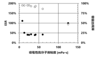
- the wound body is immersed in the conductive polymer liquid having a viscosity of 10 mPa ⁇ s or more and 60 mPa ⁇ s or less.
- the solid electrolytic capacitor of this embodiment includes a wound body in which an anode foil and a cathode foil, each having a dielectric film formed thereon, are wound facing each other, a hydrophobic adhesive tape that secures the circumferential surface of the wound body, and a conductive polymer that adheres to at least the dielectric film, and the conductive polymer is formed using a conductive polymer liquid in which the conductive polymer is dispersed or dissolved and has a viscosity of 10 mPa ⁇ s to 60 mPa ⁇ s.
- the conductive polymer may be attached by impregnating the wound body with the conductive polymer liquid.
- the conductive polymer liquid may contain water as a solvent.
- the conductive polymer liquid may further contain a high boiling point solvent.
- the method may further include an electrolyte impregnation step of impregnating the wound body with an electrolyte.
- the method may further include an electrolyte impregnated into the wound body.
- a separator having an air resistance of 5.5 [s/100 mL] or less may be interposed between the anode foil and the cathode foil and wound.
- a separator having an air resistance of 5.5 [s/100 mL] or less may be interposed between the anode foil and the cathode foil within the winding body.
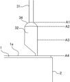
- the anode foil and the cathode foil are connected to a lead terminal having a flat portion, a round bar portion, and a lead wire in series at the flat portion, and the round bar portion protrudes from one end face of the wound body, and the lead wire is drawn out.
- the wound body may be immersed in the conductive polymer liquid to a height at least equal to or higher than the height of one end face of the wound body.
- the flat portion, the round bar portion, and the lead wire are connected in series, the flat portion is connected to the anode foil and the cathode foil, the round bar portion protrudes from one end face of the winding, the lead wire is connected to a lead terminal, and the conductive polymer may be attached to a height equal to or higher than the height of the one end face of the winding.
- the present invention increases the capacitance appearance rate of solid electrolytic capacitors.
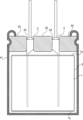
- FIG. 1 is a schematic diagram of a solid electrolytic capacitor according to an embodiment of the present invention.
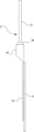
- 2 is a schematic diagram showing a state in which a lead terminal and an electrode foil of the solid electrolytic capacitor according to the embodiment are connected to each other.
- FIG. 3A and 3B are schematic diagrams showing the liquid level position of a conductive polymer liquid or the adhesion position of a conductive polymer.
- 1 is a graph showing the relationship between the ESR and the capacitance appearance rate and the viscosity of a conductive polymer liquid.
- 1 is a graph showing the relationship between the height of the immersion liquid surface of the conductive polymer liquid and the amount of the conductive polymer adhered.
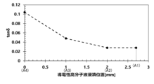
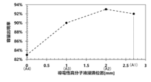
- FIG. 1 is a graph showing the relationship between the height of the immersion liquid surface of a conductive polymer liquid and tan ⁇ of a solid electrolytic capacitor. 1 is a graph showing the relationship between the height of the immersion liquid surface of the conductive polymer liquid and the capacitance appearance rate of the solid electrolytic capacitor.
- FIG. 11 is a scatter diagram showing the relationship between the ESR and the capacitance appearance rate versus the viscosity of a conductive polymer liquid.
- a solid electrolytic capacitor is a passive device that obtains capacitance through the dielectric polarization of a dielectric film and stores and discharges electric charge.
- This solid electrolytic capacitor includes an anode foil and a cathode foil on whose surface a dielectric film is formed. The anode foil and the cathode foil are arranged opposite each other.
- a separator is interposed between the anode foil and the cathode foil to prevent the anode foil and the cathode foil from shorting out.
- a conductive polymer is attached to the dielectric film of the anode foil.
- the conductive polymer is the electrolyte of the solid electrolytic capacitor, and is arranged in a line between the dielectric film and the cathode body to create a conductive path, making it the true cathode.
- a liquid electrolyte can also be used in solid electrolytic capacitors. The electrolyte fills the gap between the dielectric film and the conductive polymer.
- FIG. 1 is a schematic diagram of a wound body provided in a solid electrolytic capacitor.
- a solid electrolytic capacitor is of a wound type. That is, the solid electrolytic capacitor is provided with a wound body 1.
- the wound body 1 is formed by winding a laminate of an anode foil, a cathode foil, and a separator in a spiral shape multiple times, and has a cylindrical shape.
- the anode foil and the cathode foil are strip-shaped foil bodies. The short side of the strip is aligned with the central axis of the wound body 1, and the strip is wound so that the long side is rounded.
- the process of winding the anode foil, the cathode foil, and the separator to form the wound body 1 is called the winding process.
- each of the anode foil and cathode foil Prior to the winding process, each of the anode foil and cathode foil is connected to a lead terminal 3.
- the lead terminal 3 is electrically and mechanically connected to the anode foil and cathode foil by cold welding, ultrasonic welding, laser welding, or the like.
- the lead terminal 3 protrudes from one of the lead-out end faces 1a of the winding body 1 and is an electrical conductor that electrically connects the solid electrolytic capacitor to the mounting board.
- a strip of adhesive tape 2 is wound around the outer circumference of the wound body 1. At least the outer end of the strip of adhesive tape 2 is secured to prevent the wound body 1 from unraveling.
- the process of securing the outer surface of the wound body 1 with adhesive tape 2 is called the winding securing process.
- the adhesive tape 2 has a hydrophobic base material such as polypropylene to provide resistance to moisture during the manufacturing process of the solid electrolytic capacitor. An adhesive layer is laminated on this hydrophobic base material, and the adhesive tape 2 is hydrophobic.
- the width of this adhesive tape 2 in the short direction of the band is the same or approximately the same as the axial length of the roll 1.
- the adhesive tape 2 is wound around the roll 1 so as to cover at least the outer end of the band of the roll 1.
- the adhesive tape 2 is also wound around the roll 1 so that the edges of the adhesive tape 2 in the long direction of the band are flush or approximately flush with the lead-out end face 1a and the opposite end face 1b of the roll 1.
- the process moves to the solid electrolyte formation process.
- a conductive polymer is attached to the inside of the wound body 1.
- the conductive polymer covers at least a part of the dielectric film.
- the conductive polymer is formed in the wound body 1 using a conductive polymer liquid.
- the conductive polymer liquid is a dispersion or solution in which a conductive polymer is dispersed or dissolved.
- the main solvent of the conductive polymer liquid is water, in which conductive polymer powder or particles are dispersed or dissolved.
- the wound body 1 is immersed in the conductive polymer liquid, and the wound body 1 is impregnated with the conductive polymer liquid.
- the wound body 1 may be immersed in the conductive polymer liquid once or multiple times.
- the wound body 1 may be impregnated with the conductive polymer liquid in a reduced pressure environment.
- the solvent in the conductive polymer liquid is removed by drying.
- the temperature environment is, for example, 40°C or higher and 200°C or lower, and the drying time is, for example, in the range of 3 minutes or higher and 180 minutes or lower.
- the drying process may be repeated multiple times. Drying may be performed in a reduced pressure environment, for example, by reducing the pressure to 5 kPa or higher and 100 kPa or lower.
- the solid electrolyte formation process is followed by an impregnation process in which the electrolyte is impregnated.
- the wound body 1 with the conductive polymer attached is impregnated with the electrolyte once or multiple times in an atmospheric pressure environment or a reduced pressure environment.
- the wound body 1 filled with the conductive polymer or both the conductive polymer and the electrolyte, i.e., the capacitor element is inserted into a cylindrical exterior case 41 with a bottom and sealed with a sealing member 42.
- the sealing member 42 is an elastic body for sealing the capacitor element within the exterior case, and has an insertion hole 43 through which the lead terminal 3 passes. The lead terminal 3 is pressed into the insertion hole 43 and pulled out from the sealing member 42.
- the manufacture of the solid electrolytic capacitor is completed after an aging process. In the aging process, a DC voltage is applied to the solid electrolytic capacitor to repair defects in the dielectric film layer, etc.
- the capacitor element may be covered with a laminate film instead of an exterior case.
- the capacitor element may also be molded with a resin such as a heat-resistant resin or an insulating resin.
- the capacitor element may be sealed by forming the resin into a thin film using a method such as dip coating or printing.
- the anode foil is a long foil made of a valve metal, such as aluminum, tantalum, niobium, niobium oxide, titanium, hafnium, zirconium, zinc, tungsten, bismuth, and antimony.
- the cathode foil is a long foil made of the same valve metal as the anode foil or other metals, such as silver.
- the cathode foil may be a layered foil having a carbon layer laminated on a silver layer.
- the purity of the anode foil is preferably 99.9% or more, and that of the cathode foil is preferably 99% or more, but may contain silicon, iron, copper, magnesium, zinc, and the like.
- the long foil may be formed by stretching valve metal or the like, or by sintering valve metal powder.
- a surface expansion layer is formed on one or both sides of the anode foil.
- the surface expansion layer is an etching layer formed by etching the foil, a sintered layer formed by sintering valve metal powder, or a deposition layer formed by depositing valve metal particles onto the foil.
- the surface expansion layer has a porous structure, consisting of tunnel-shaped pits, spongy pits, or spaces between densely packed powder or particles.
- Tunnel-shaped etching pits are holes dug in the thickness direction of the foil. These tunnel-shaped etching pits are typically formed by passing a direct current in an acidic aqueous solution, such as hydrochloric acid, in which halogen ions are present. The tunnel-shaped etching pits are further expanded in diameter by passing a direct current in an acidic aqueous solution, such as nitric acid. The spongy etching pits make the expanded surface layer into a sponge-like layer with fine gaps that are connected together in a space. These spongy etching pits are formed by passing an alternating current in an acidic aqueous solution, such as hydrochloric acid, in which halogen ions are present.
- the sintered layer is produced by obtaining a powder of a valve action metal of the same or different type as the foil body by a milling method, atomization method, melt spinning method, rotating disk method, rotating electrode method, etc., forming it into a paste using a binder or solvent, applying it to the foil body, drying it, and heating and sintering it in a vacuum or reducing atmosphere, etc.
- the atomization method may be any of water atomization method, gas atomization method, and water gas atomization method.
- the vapor deposition layer is produced by, for example, resistance heating vapor deposition method or electron beam heating vapor deposition method. This vapor deposition layer is formed by heating and evaporating a valve action metal of the same or different type as the foil body by resistance heat or electron beam energy, and depositing the vapor of the valve action metal particles on the surface of the foil body.
- the dielectric film is formed on the uneven surface of the surface-expanding layer.
- the dielectric film is typically an oxide film formed on the uneven surface of the surface-expanding layer, and if the anode foil is made of aluminum, it is an aluminum oxide layer formed by oxidizing the uneven surface of the surface-expanding layer.
- a voltage is applied to the anode foil in a chemical conversion solution until the desired withstand voltage is achieved.
- the chemical conversion solution is a solution that does not contain halogen ions, and examples of such solutions include phosphoric acid-based chemical conversion solutions such as ammonium dihydrogen phosphate, boric acid-based chemical conversion solutions such as ammonium borate, and adipic acid-based chemical conversion solutions such as ammonium adipate.
- phosphoric acid-based chemical conversion solutions such as ammonium dihydrogen phosphate
- boric acid-based chemical conversion solutions such as ammonium borate
- adipic acid-based chemical conversion solutions such as ammonium adipate.
- a surface enlargement layer may be formed on cathode foil as necessary. Plain foil without a surface enlargement layer may also be used as cathode foil.
- Cathode foil may have a dielectric film formed thereon as with anode foil.
- the dielectric film may be a natural oxide film, or a thin oxide film (approximately 1 to 10 V) formed by chemical conversion treatment. The natural oxide film is formed when the cathode foil reacts with oxygen in the air.
- the cathode foil may have a conductive layer laminated on the foil surface.
- the conductive layer is, for example, a layer containing a metal nitride such as titanium, zirconium, tantalum, or niobium, a metal carbide, a metal carbonitride, or carbon.
- the metal nitride, metal carbide, metal carbonitride, and carbon are formed by a deposition method, a slurry coating method, or the like.
- (Lead terminal) 2 is a schematic diagram of the lead terminal 3.
- the lead terminal 3 is drawn through the sealing member 4, and is configured with a lead wire 31, a round bar portion 32, and a flat portion 33 arranged in a series.
- the sealing member 42 is an elastic body for sealing the capacitor element in an exterior case, and has an insertion hole 43 through which the lead terminal 3 passes.
- the lead wire 31 is an electric wire that extends outside the sealing member 42 and electrically connects the solid electrolytic capacitor to the mounting board.
- This lead wire 31 is generally a copper-coated steel wire called a CP wire, and the surface is solder-plated with lead, tin, or the like.
- the round bar portion 32 is typically made of aluminum and is a generally cylindrical round bar.
- the cross-sectional shape of the round bar portion 32 is not limited to a perfect circle, and may be an ellipse, a polygonal shape such as a triangle or a rectangle, or another shape.
- the lead wire 31 and the round bar portion 32 are connected by arc welding or the like, and a connection portion 34 is interposed between the lead wire 31 and the round bar portion 32 by welding.
- the lead wire 31 may be formed from a part of the round bar portion 32.
- the round bar portion 32 is set to be one size larger than the insertion hole 43 of the sealing member 42. The round bar portion 32 is pressed into the insertion hole 43, and is in close contact with the inner wall of the insertion hole 43 due to the increase in internal pressure of the sealing member 42 after it is crimped.
- the flat portion 33 is formed by crushing the side of the round bar portion 32 opposite the lead wire 31 by pressing or the like into a flat plate shape.
- the boundary between the round bar portion 32 and the flat portion 33 is an inclined portion whose thickness decreases linearly to the thickness of the flat portion 33. This inclined portion is included in the round bar portion 32.
- the flat portion 33 is electrically and mechanically connected to each electrode foil 5, which is a collective term for anode foil and cathode foil, using one of various connection methods such as stitch connection, cold pressure welding, ultrasonic welding, or laser welding.
- the flat portion 33 is brought into contact with one side and one side of the long side of the electrode foil 5, and the round bar portion 32 and the lead wire 31 are allowed to protrude from the electrode foil 5 so as to be perpendicular to the long side of the electrode foil 5, connecting the flat portion 33 and the electrode foil 5.
- the winding process is performed after the lead terminals 3 are connected to each electrode foil 5.
- the separator prevents short-circuiting between the anode foil and the cathode foil, and holds the conductive polymer and the electrolyte.
- the separator may be made of cellulose such as kraft, Manila hemp, esparto, hemp, rayon, or a mixture of these, polyester resins such as polyethylene terephthalate, polybutylene terephthalate, polyethylene naphthalate, or derivatives thereof, polytetrafluoroethylene resins, polyvinylidene fluoride resins, vinylon resins, polyamide resins such as aliphatic polyamides, semi-aromatic polyamides, or fully aromatic polyamides, polyimide resins, polyethylene resins, polypropylene resins, trimethylpentene resins, polyphenylene sulfide resins, acrylic resins, polyvinyl alcohol resins, or the like, which may be used alone or in combination.
- the separator may be fibrillated by generating thin fibers that branch out from the surface of the original fibers, for example, fibrillated cellulose. Fibrillation can be achieved, for example, by beating. The fibrillated fibers are entangled with each other using the fibrillated thin fibers, improving the strength of the separator. This allows the separator to be made thinner.
- a separator with an air resistance of 5.5 [s/100 mL] or less for the wound body 1. If the separator has an air resistance of 5.5 [s/100 mL] or less, the conductive polymer liquid will easily seep into the wound body 1 during the solid electrolyte formation process. This increases the amount of conductive polymer liquid impregnated into the wound body 1 and the amount of conductive polymer attached to the wound body 1, improving the appearance rate of solid electrolytic capacitors.
- the air permeability resistance is also called the Gurley value, and is the time required for 100 mL of air to permeate the separator.
- the air permeability resistance is measured by the Gurley method according to JIS P8117:2009.
- a gasket with an inner diameter of 28.6 mm is used for the measurement.
- a gasket with an inner diameter of 6 mm is used for the measurement, and the value is converted to the value measured with an inner diameter of 28.6 mm.
- a conversion formula is used in which the value obtained with an inner diameter of 6 mm is multiplied by 6 2 /28.6 2 .
- Conductive polymers are self-doped conjugated polymers doped with an intramolecular dopant, or conjugated polymers doped with an external dopant molecule.
- Conjugated polymers are obtained by chemical oxidative polymerization or electrolytic oxidative polymerization of a monomer having a ⁇ -conjugated double bond or a derivative thereof.
- the dopant or external dopant molecule is an acceptor that easily accepts electrons into the conjugated polymer, or a donor that easily gives electrons to the conjugated polymer, which allows the conductive polymer to exhibit high conductivity.
- conjugated polymers can be used without any particular limitations. Examples include polypyrrole, polythiophene, polyfuran, polyaniline, polyacetylene, polyphenylene, polyphenylenevinylene, polyacene, polythiophenevinylene, etc. These conjugated polymers may be used alone, or two or more types may be combined, or they may be copolymers of two or more types of monomers.
- conjugated polymers formed by polymerizing thiophene or its derivatives
- conjugated polymers formed by polymerizing 3,4-ethylenedioxythiophene i.e., 2,3-dihydrothieno[3,4-b][1,4]dioxine
- 3-alkylthiophene 3-alkoxythiophene
- 3-alkyl-4-alkoxythiophene 3,4-alkylthiophene, 3,4-alkoxythiophene, or derivatives thereof.
- thiophene derivative a compound selected from thiophenes having substituents at the 3rd and 4th positions is preferred, and the substituents at the 3rd and 4th positions of the thiophene ring may form a ring together with the carbons at the 3rd and 4th positions.
- the alkyl group or alkoxy group preferably has 1 to 16 carbon atoms.
- a polymer of 3,4-ethylenedioxythiophene called EDOT i.e., poly(3,4-ethylenedioxythiophene) called PEDOT
- a substituent may be added to 3,4-ethylenedioxythiophene.
- an alkylated ethylenedioxythiophene having an alkyl group having 1 to 5 carbon atoms added as a substituent may be used.
- alkylated ethylenedioxythiophene examples include methylated ethylenedioxythiophene (i.e., 2-methyl-2,3-dihydro-thieno[3,4-b][1,4]dioxine), ethylated ethylenedioxythiophene (i.e., 2-ethyl-2,3-dihydro-thieno[3,4-b][1,4]dioxine), butylated ethylenedioxythiophene (i.e., 2-butyl-2,3-dihydro-thieno[3,4-b][1,4]dioxine), and 2-alkyl-3,4-ethylenedioxythiophene.
- methylated ethylenedioxythiophene i.e., 2-methyl-2,3-dihydro-thieno[3,4-b][1,4]dioxine
- ethylated ethylenedioxythiophene i
- dopant can be used without any particular limitation.
- a single dopant may be used, or two or more dopants may be used in combination.
- a polymer or monomer may also be used.
- dopants include inorganic acids such as polyanions, boric acid, nitric acid, and phosphoric acid, and organic acids such as acetic acid, oxalic acid, citric acid, tartaric acid, squaric acid, rhodizonic acid, croconic acid, salicylic acid, p-toluenesulfonic acid, 1,2-dihydroxy-3,5-benzenedisulfonic acid, methanesulfonic acid, trifluoromethanesulfonic acid, borodisalicylic acid, bisoxalateborate acid, sulfonylimide acid, dodecylbenzenesulfonic acid, propylnaphthalenesulfonic acid, and butylnaphthalenesulfonic acid
- Polyanions include, for example, substituted or unsubstituted polyalkylenes, substituted or unsubstituted polyalkenylenes, substituted or unsubstituted polyimides, substituted or unsubstituted polyamides, and substituted or unsubstituted polyesters, and include polymers consisting only of structural units having an anionic group, and polymers consisting of structural units having an anionic group and structural units not having an anionic group.
- polyanions include polyvinyl sulfonic acid, polystyrene sulfonic acid, polyallylsulfonic acid, polyacrylic sulfonic acid, polymethacrylic acid, poly(2-acrylamido-2-methylpropanesulfonic acid), polyisoprene sulfonic acid, polyacrylic acid, polymethacrylic acid, and polymaleic acid.
- PEDOT/PSS poly(3,4-ethylenedioxythiophene) doped with polystyrene sulfonic acid, and hereafter this conductive polymer will be referred to as PEDOT/PSS.
- the wound body 1 is immersed in a conductive polymer liquid to adhere the conductive polymer to the inside of the wound body 1.
- the conductive polymer liquid is a dispersion liquid in which a conductive polymer is dispersed or a solution in which a conductive polymer is dissolved.
- the conductive polymer liquid is prepared by purifying the solution after electrolytic polymerization or chemical polymerization by ultrafiltration, cation exchange, anion exchange, etc., removing residual monomers and impurities, and dispersing or dissolving the conductive polymer in a solvent, or by adding particles or powder of the conductive polymer to a solvent and dispersing or dissolving the conductive polymer in the solvent.
- the main solvent for the conductive polymer liquid is water.
- the viscosity of the conductive polymer liquid is adjusted to 10 mPa ⁇ s or more and 60 mPa ⁇ s or less by, for example, the processing time by a dispersion method such as an ultrasonic homogenizer or jet mixing, the type and amount of the dispersion medium, the type and amount of the additive, the degree of polymerization of the polymer, the polymer concentration, etc. If the viscosity is within this range, the conductive polymer liquid can easily permeate the wound body 1 while maintaining a good ESR of the solid electrolytic capacitor, thereby improving the capacitance appearance rate of the solid electrolytic capacitor. However, if the viscosity is less than 10 mPa ⁇ s, the ESR will increase rapidly. Also, if the viscosity exceeds 60 mPa ⁇ s, the capacitance appearance rate will decrease rapidly.
- the capacitance occurrence rate is the ratio of the capacitance of the solid electrolytic capacitor to the combined capacitance of the anode foil and cathode foil, and is the percentage obtained by dividing the capacitance of the solid electrolytic capacitor by the combined capacitance of the anode foil and cathode foil.
- the combined capacitance of the anode foil and cathode foil is the combined capacitance when the solid electrolytic capacitor is regarded as a capacitor with the anode side and cathode side connected in series.
- the cathode foil has a conductive layer, or if the capacitance of the cathode body can be said to converge to infinity, the combined capacitance of the anode foil and cathode foil is the capacitance of the anode foil.
- the solvent for the conductive polymer dispersion may be a mixture of water and an organic solvent, so long as the conductive polymer particles or powder can be dispersed or dissolved in the solvent.
- organic solvents include polar solvents, alcohols, esters, hydrocarbons, carbonate compounds, ether compounds, chain ethers, heterocyclic compounds, and nitrile compounds.
- Polar solvents include N-methyl-2-pyrrolidone, N,N-dimethylformamide, N,N-dimethylacetamide, dimethylsulfoxide, etc.
- Alcohols include methanol, ethanol, propanol, butanol, etc.
- Esters include ethyl acetate, propyl acetate, butyl acetate, etc.
- Hydrocarbons include hexane, heptane, benzene, toluene, xylene, etc.
- Carbonate compounds include ethylene carbonate, propylene carbonate, etc.
- Ether compounds include dioxane, diethyl ether, etc.
- Chain ethers include ethylene glycol dialkyl ether, propylene glycol dialkyl ether, polyethylene glycol dialkyl ether, polypropylene glycol dialkyl ether, etc.
- Heterocyclic compounds include 3-methyl-2-oxazolidinone, etc.
- Nitrile compounds include acetonitrile, glutarodinitrile, methoxyacetonitrile, propionitrile, benzonitrile, etc.
- the pH of the conductive polymer liquid may be adjusted, and polyhydric alcohols and various additives may be added as necessary.
- pH adjusters include ammonia water, sodium hydroxide, primary amines, secondary amines, and tertiary amines.
- polyhydric alcohols include sorbitol, ethylene glycol, diethylene glycol, triethylene glycol, polyoxyethylene glycol, polyoxypropylene glycol, glycerin, polyglycerin, polyoxyethylene glycerin, xylitol, erythritol, mannitol, dipentaerythritol, pentaerythritol, and combinations of two or more of these.
- Polyhydric alcohols are high-boiling point solvents, and remain in the wound body 1 even after the wound body 1 is impregnated with the conductive polymer liquid and dried.
- the polyhydric alcohols have the effect of reducing the ESR and improving the withstand voltage of the solid electrolytic capacitor.
- additives include organic binders, surfactants, dispersants, defoamers, coupling agents, antioxidants, and ultraviolet absorbers.
- FIG. 3 is a schematic diagram showing the liquid level position of the conductive polymer liquid or the position where the conductive polymer is attached.
- the boundary position between the lead wire 31 of the lead terminal 3 and the upper end of the connection portion 34 is defined as the upper end A1 of the connection portion.
- the boundary position between the lower end of the connection portion 34 of the lead terminal 3 and the round bar portion 32 is defined as the lower end A2 of the connection portion.
- A3 is a position 1 mm or more from the lead end surface 1a of the wound body 1.
- A3 is, for example, a half-height position in the length direction of the round bar portion 32.
- the lead end surface 1a of the wound body 1 is defined as the end surface position A4.
- the liquid level of the conductive polymer liquid is located at least on the lead-out end surface 1a of the wound body 1. It is also preferable to immerse the wound body 1 in the conductive polymer liquid so that the liquid level of the conductive polymer liquid is located between a height position A3 of 1 mm or more from the lead-out end surface 1a of the wound body 1 and the upper end A1 of the connection part, for example, the halfway position A3 of the round bar. In other words, it is preferable to attach the conductive polymer to the lead terminal 3 in the range between at least the position A3 and the upper end A1 of the connection part, in addition to the inside of the wound body 1. Since the contact angle between the hydrophobic adhesive tape and the conductive polymer liquid is large, a meniscus is formed. Therefore, it is necessary to immerse the wound body 1 in the conductive polymer liquid beyond the upper end edge of the hydrophobic adhesive tape 2.
- the conductive polymer liquid is sucked up from the opposite end face 1b and drips down from the outlet end face 1a.
- a separator with an air resistance of 5.5 [s/100 mL] or less, the conductive polymer liquid that enters from the outlet end face 1a and the opposite end face 1b permeates through the separator and into the wound body 1.
- the round bar portion 32 is immersed in the conductive polymer liquid at least to a height equal to or greater than the position A3, and in addition to the wound body 1, the conductive polymer adheres to the round bar portion 32 at least to a height equal to or greater than the position A3, thereby increasing the capacitance appearance rate of the solid electrolytic capacitor and reducing the dielectric loss tangent (tan ⁇ ).
- the time for impregnation with the conductive polymer liquid can be set appropriately depending on the size of the wound body 1. Long periods of impregnation do not adversely affect the properties.
- decompression or pressure treatment may be performed as necessary to promote impregnation.
- the solid electrolyte formation process may be repeated multiple times.
- the solvent of the conductive polymer liquid is evaporated and removed by drying as necessary. Heat drying or reduced pressure drying may be performed as necessary to remove the solvent.
- a repair chemical treatment may be performed to repair defects such as voids, cracks, or scratches in various parts of the dielectric film caused by insufficient formation of the dielectric film and bending stress caused by winding.
- the chemical solution used for the repair chemical conversion is an aqueous solution of phosphoric acid such as ammonium dihydrogen phosphate or diammonium hydrogen phosphate, boric acid such as ammonium borate, or adipic acid such as ammonium adipate dissolved in water.
- the voltage is preferably set to, for example, 0.1 to 1.2 times the chemical conversion voltage.
- the electrolyte is a mixed solution in which a solute is dissolved in a solvent and an additive is added as necessary.
- the electrolyte does not need to dissolve a solute, and may be a solvent only, or may contain a solvent and an additive.
- the solvent for the electrolyte includes a protic organic polar solvent or an aprotic organic polar solvent, which may be used alone or in combination of two or more.
- the solute for the electrolyte includes an anion component and a cation component.
- the solute is typically a salt of an organic acid, a salt of an inorganic acid, or a salt of a complex compound of an organic acid and an inorganic acid, which may be used alone or in combination of two or more.
- An acid that becomes an anion and a base that becomes a cation may be added separately to the solvent.
- Protic organic polar solvents which are solvents, include monohydric alcohols, polyhydric alcohols, and oxyalcohol compounds.
- monohydric alcohols include ethanol, propanol, butanol, pentanol, hexanol, cyclobutanol, cyclopentanol, cyclohexanol, and benzyl alcohol.
- polyhydric alcohols and oxyalcohol compounds examples include ethylene glycol, propylene glycol, glycerin, polyglycerin, methyl cellosolve, ethyl cellosolve, methoxypropylene glycol, dimethoxypropanol, and alkylene oxide adducts of polyhydric alcohols such as polyethylene glycol and polyoxyethylene glycerin.
- polyhydric alcohols are preferable as the solvent, and ethylene glycol and glycerin are particularly preferable.
- Ethylene glycol and glycerin cause a change in the higher-order structure of the conductive polymer, resulting in good initial ESR characteristics and also good high-temperature characteristics. It is even better if the ethylene glycol is 30 wt% or more in the solvent.
- aprotic organic polar solvents include sulfones, amides, lactones, cyclic amides, nitriles, and sulfoxides.
- sulfones include dimethyl sulfone, ethyl methyl sulfone, diethyl sulfone, sulfolane, 3-methyl sulfolane, and 2,4-dimethyl sulfolane.
- amides include N-methylformamide, N,N-dimethylformamide, N-ethylformamide, N,N-diethylformamide, N-methylacetamide, N,N-dimethylacetamide, N-ethylacetamide, N,N-diethylacetamide, and hexamethylphosphoric amide.
- lactones and cyclic amides include ⁇ -butyrolactone, ⁇ -valerolactone, ⁇ -valerolactone, N-methyl-2-pyrrolidone, ethylene carbonate, propylene carbonate, butylene carbonate, and isobutylene carbonate.
- nitriles include acetonitrile, 3-methoxypropionitrile, and glutaronitrile.
- sulfoxides include dimethyl sulfoxide.
- Organic acids that act as anionic solutes include carboxylic acids such as oxalic acid, succinic acid, glutaric acid, pimelic acid, suberic acid, sebacic acid, phthalic acid, isophthalic acid, terephthalic acid, maleic acid, adipic acid, benzoic acid, toluic acid, enanthic acid, malonic acid, 1,6-decanedicarboxylic acid, 1,7-octanedioic acid, azelaic acid, undecanedioic acid, dodecanedioic acid, tridecanedioic acid, t-butyl adipic acid, 11-vinyl-8-octadecenedioic acid, resorcylic acid, phloroglucinic acid, gallic acid, gentisic acid, protocatechuic acid, pyrocatechuic acid, trimellitic acid, and pyromellitic acid, as well as phenol
- Inorganic acids include boric acid, phosphoric acid, phosphorous acid, hypophosphorous acid, carbonic acid, and silicic acid.
- Examples of composite compounds of organic acids and inorganic acids include borodisalicylic acid, borodioxalic acid, borodiglycolic acid, borodimalonic acid, borodisuccinic acid, borodiadipic acid, borodiazelaic acid, borodibenzoic acid, borodimaleic acid, borodilactic acid, borodimalic acid, boroditartaric acid, borodicitric acid, borodiphthalic acid, borodi(2-hydroxy)isobutyric acid, borodiresorcylic acid, borodimethylsalicylic acid, borodinaphthoic acid, borodimandelic acid, and borodi(3-hydroxy)propionic acid.
- examples of at least one salt of an organic acid, an inorganic acid, or a complex compound of an organic acid and an inorganic acid include ammonium salts, quaternary ammonium salts, quaternary amidinium salts, amine salts, sodium salts, potassium salts, etc.
- examples of quaternary ammonium ions of quaternary ammonium salts include tetramethylammonium, triethylmethylammonium, tetraethylammonium, etc.
- Examples of quaternary amidinium include ethyldimethylimidazolinium, tetramethylimidazolinium, etc.
- Examples of amine salts include salts of primary amines, secondary amines, and tertiary amines.
- Examples of primary amines include methylamine, ethylamine, propylamine, etc.
- examples of secondary amines include dimethylamine, diethylamine, ethylmethylamine, dibutylamine, etc.
- examples of tertiary amines include trimethylamine, triethylamine, tributylamine, ethyldimethylamine, ethyldiisopropylamine, etc.
- additives can be added to the electrolyte.
- additives include complex compounds of boric acid and polysaccharides (mannitol, sorbitol, etc.), complex compounds of boric acid and polyhydric alcohols, boric acid esters, nitro compounds (o-nitrobenzoic acid, m-nitrobenzoic acid, p-nitrobenzoic acid, o-nitrophenol, m-nitrophenol, p-nitrophenol, p-nitrobenzyl alcohol, etc.), and phosphate esters. These may be used alone or in combination of two or more. There are no particular restrictions on the amount of additive added, but it is preferable to add an amount that does not deteriorate the characteristics of the solid electrolytic capacitor, for example, 60 wt % or less in the electrolyte.
- Examples 1 to 7 As described below, solid electrolytic capacitors of Examples 1 to 7 and Comparative Examples 1 and 2 were fabricated. The solid electrolytic capacitors of Examples 1 to 7 and Comparative Examples 1 and 2 are common to all but the viscosity of the conductive polymer solution used in the fabrication was different.
- the anode foil and cathode foil were strip-shaped aluminum foil stretched into a long length.
- the anode foil and cathode foil were enlarged in surface area by direct current etching. After enlarging the surface area of the anode foil, it was subjected to chemical conversion treatment and a dielectric film was formed.
- a lead terminal 3 was attached to each of the anode foil and cathode foil by stitch connection.
- a separator made of fibrillated cellulose was placed between the anode foil and cathode foil to which the lead terminal 3 was connected, and the strip was wound so that the longitudinal direction of the strip was curled, forming a wound body 1.
- a separator made of fibrillated cellulose and having an air resistance of 5.48 [s/100 mL] was used.
- An adhesive tape 2 with the same width as the entire axial length of the wound body 1 was prepared, and the outer periphery of the wound body 1 was wrapped around with this adhesive tape 2.
- the wound body 1 was impregnated with a conductive polymer liquid.
- the conductive polymer liquid was prepared by dispersing poly(3,4-ethylenedioxythiophene) (PEDOT/PSS) doped with polystyrene sulfonic acid (PSS) in water. PEDOT/PSS was added at a ratio of 1.2 wt% to the entire conductive polymer liquid. Ethylene glycol was also added to the conductive polymer liquid at a ratio of 10 wt% to the conductive polymer liquid. In the solid electrolytic capacitor of Example 1, the viscosity of the conductive polymer liquid was adjusted by dispersing it with an ultrasonic homogenizer.
- the wound body 1 was impregnated with the conductive polymer liquid for 10 minutes at room temperature and in a reduced pressure environment of 80 kPa or less.
- the wound body 1 was immersed in the conductive polymer liquid so that the liquid level was located at the lower end A2 of the connection part shown in Figure 3, and the conductive polymer was attached up to the height of the lower end A2 of the connection part.
- the wound body 1 was left to stand at room temperature for 10 minutes, and then left to stand in a temperature environment of 110°C for 30 minutes to dry it.
- the wound body 1 After being impregnated with the conductive polymer and dried, the wound body 1 was housed in an outer case 41, and the outer case 41 was sealed with a sealing member 42. The sealing member 42 and the outer case 41 were tightly attached by crimping. The lead terminal 3 was pressed into the insertion hole 43 of the sealing member 42, and the outer surface of the round bar portion 32 was tightly attached to the inner surface of the insertion hole 43.
- the completed solid electrolytic capacitor was subjected to an aging process in which a voltage of 40 V was applied for 1 hour. As a result, the electrolytic capacitor of Example 1 was produced, with a diameter of 10 mm, a height of 10 mm, a rated voltage of 35 WV, and a rated capacitance of 270 ⁇ F.
- ESR equivalent series resistance
- the capacitance of the anode foil or cathode foil was measured by cutting a test piece of a specified area from the anode foil or cathode foil, immersing it in a capacitance measurement solution in a glass measurement tank with a platinum plate as the counter electrode, and using a capacitance meter.
- the specified area was 1 cm2
- the capacitance measurement solution was an aqueous solution of ammonium adipate at 30°C
- the capacitance meter was an LCR meter
- the measurement conditions were an AC amplitude of 0.5 Vms.
- the conductive polymer is formed using a conductive polymer liquid with a viscosity of 60 mPa ⁇ s or less.
- the solid electrolytic capacitors of Comparative Example 1 and Examples 1 to 7 had a good capacitance appearance rate.
- Comparative Example 1 in which the conductive polymer was formed using a conductive polymer liquid with a viscosity of less than 10 mPa ⁇ s, had a high ESR.
- Examples 1 to 7 in which the conductive polymer was formed using a conductive polymer liquid with a viscosity of 10 mPa ⁇ s or more and 60 mPa ⁇ s or less, had a good capacitance appearance rate and also a good ESR.
- Example 8 A solid electrolytic capacitor of Example 8 was produced.
- Example 8 is common to Example 4 in the following respects. That is, in the solid electrolytic capacitor of Example 8, a conductive polymer liquid having a viscosity of 30 mPa ⁇ s was impregnated into the wound body 1, as in Example 4. The wound body 1 was immersed in the conductive polymer liquid so that the liquid level of the conductive polymer liquid was located at the lower end A2 of the connection part shown in FIG. 3, and the conductive polymer was attached up to the height of the lower end A2 of the connection part. The lower end A2 of the connection part is a position 2 mm from the lead-out end surface 1a of the wound body 1. However, Example 8 is different from Example 4, and a separator with an air resistance of 5.76 [s/100 mL] was used. In other respects, Example 8 has the same configuration as Example 4, and was produced by the same manufacturing method and manufacturing conditions.
- Example 8 in which the separator has an air permeability resistance of 5.76 [s/100 mL] is good, unlike Comparative Example 2, but is lower than that of Example 4.
- the viscosity of the conductive polymer liquid is 10 mPa ⁇ s or more and 60 mPa ⁇ s or less, and the separator has an air permeability resistance of 5.5 [s/100 mL] or less, which includes the range of Examples 1 to 8, the capacitance appearance rate of the solid electrolytic capacitor is further improved.
- Example 9 A solid electrolytic capacitor of Example 9 was produced.
- Example 9 is common to Example 4 in the following respects. That is, in the solid electrolytic capacitor of Example 9, as in Example 4, a fillerated cellulose having an air resistance of 5.48 [s/100 mL] was used as a separator. A conductive polymer liquid having a viscosity of 30 mPa ⁇ s was impregnated into the wound body 1. However, unlike Example 4, the wound body 1 of Example 9 was immersed in the conductive polymer liquid so that the liquid level of the conductive polymer liquid was located at the upper end A1 of the connection part shown in FIG. 3, and the conductive polymer was attached up to the height of the upper end A1 of the connection part. In other respects, Example 9 has the same configuration as Example 4, and was produced by the same manufacturing method and manufacturing conditions. The upper end A1 of the connection part is located 2.7 mm from the lead-out end surface 1a of the wound body 1.
- Example 10 A solid electrolytic capacitor of Example 10 was produced.
- Example 10 is common to Example 4 in the following respects. That is, in the solid electrolytic capacitor of Example 10, as in Example 4, a fillerated cellulose having an air resistance of 5.48 [s/100 mL] was used as a separator. A conductive polymer liquid having a viscosity of 30 mPa ⁇ s was impregnated into the wound body 1. However, unlike Example 4, the wound body 1 of Example 10 was immersed in the conductive polymer liquid so that the liquid level of the conductive polymer liquid was located at position A3 shown in FIG. 3 and the conductive polymer was attached up to the height of the upper end A1 of the connection part. In other respects, Example 10 has the same configuration as Example 4 and was produced by the same manufacturing method and manufacturing conditions. Position A3 is a position 1 mm from the lead-out end surface 1a of the wound body 1.
- Example 11 A solid electrolytic capacitor of Example 11 was produced.
- Example 11 has the following in common with Example 4. That is, in the solid electrolytic capacitor of Example 11, a fillerated cellulose having an air resistance of 5.48 [s/100 mL] was used as a separator, as in Example 4.
- a conductive polymer liquid having a viscosity of 30 mPa ⁇ s was impregnated into the wound body 1.
- the wound body 1 of Example 11 was immersed in the conductive polymer liquid so that the liquid level of the conductive polymer liquid was located at the end face position A4 shown in FIG. 3, and the conductive polymer was attached up to the height of the end face position A4.
- Example 11 has the same configuration as Example 4, and was produced by the same manufacturing method and manufacturing conditions.
- Adhesion amount test The amount of the conductive polymer solution impregnated in the wound body 1 of Example 4 and Examples 9 to 11 was measured. The adhesion amount was calculated from the change in weight of the wound body 1 before and after the solid electrolyte formation step. The adhesion amount of Example 4 and Examples 9 to 10 is shown with the adhesion amount of Example 11 as the reference (100%).
- connection part which are in the height range of the connection part 34 between the round bar part 32 and the lead wire 31
- the amount of conductive polymer liquid adhered was further improved compared to when the immersion liquid level height of the conductive polymer liquid and the conductive polymer adhesion height were set to the end face position A4.
- Capacitor characteristics The dielectric loss tangent (tan ⁇ ) and capacitance appearance rate (%) of the solid electrolytic capacitors of Example 4 and Examples 9 to 11 were measured. The results are shown in Figures 6 and 7. The measurement results of the capacitance appearance rate (%) are shown in Table 3 below, and the measurement results of the dielectric loss tangent (tan ⁇ ) are shown in Table 4 below.
- the dielectric loss tangent (tan ⁇ ) was measured at room temperature using an LCR meter. The measurement frequency of tan ⁇ was 120 Hz, and the AC amplitude was a sine wave of 0.5 Vms.
- the viscosity of the conductive polymer liquid is set to 10 mPa ⁇ s or more and 60 mPa ⁇ s or less, making it easier to spread the conductive polymer throughout the wound body 1.
- the immersion liquid surface of the conductive polymer liquid is set to 10 mPa ⁇ s or more and 60 mPa ⁇ s or less, making it easier to spread the conductive polymer throughout the wound body 1.
- Example 12 to 14 Solid electrolytic capacitors of Examples 12 to 14 were produced.
- Examples 12 to 14 are common to Example 1 in the following respects. That is, in the solid electrolytic capacitors of Examples 12 to 14, as in Example 1, the wound body 1 was impregnated with a conductive polymer liquid having a viscosity of 13 mPa ⁇ s. The wound body 1 was immersed in the conductive polymer liquid so that the liquid level of the conductive polymer liquid was located at the lower end A2 of the connection portion shown in FIG. 3, and the conductive polymer was attached up to the height of the lower end A2 of the connection portion. The lower end A2 of the connection portion is located 2 mm from the lead-out end surface 1a of the wound body 1.
- Example 12 the solid electrolytic capacitors of Examples 12 to 14 use a separator made of natural cellulose with an air resistance of 0.03 [s/100 mL].
- Examples 12 to 14 differ from each other in the viscosity of the conductive polymer liquid impregnated into the wound body 1.
- the wound body 1 was impregnated with a conductive polymer liquid with a viscosity of 13 mPa ⁇ s.
- the wound body 1 was impregnated with a conductive polymer liquid with a viscosity of 25 mPa ⁇ s.
- Example 14 unlike Example 12, the wound body 1 was impregnated with a conductive polymer liquid with a viscosity of 60 mPa ⁇ s.
- Examples 12 to 14 have the same configuration as Example 1 and were produced using the same manufacturing method and conditions.
- a solid electrolytic capacitor of Comparative Example 3 was also produced.
- the solid electrolytic capacitor of Comparative Example 3 had the same configuration as Examples 12 to 14, except that the wound body 1 was impregnated with a conductive polymer liquid having a viscosity of 125 mPa ⁇ s, and was produced using the same manufacturing method and conditions.
- Capacitor characteristics The equivalent series resistance (ESR) and capacitance appearance rate (%) of the solid electrolytic capacitors of Examples 12 to 14 and Comparative Example 3 were measured. The measurement method and conditions for ESR and capacitance appearance rate were the same as those of Examples 1 to 8. The results are shown in Table 5 below, together with the viscosities of the conductive polymer solutions used in Examples 12 to 14 and Comparative Example 3. The ESR is shown with Comparative Example 3 as the reference (100%).
- Examples 12 to 14 in which the conductive polymer was formed using a conductive polymer liquid with a viscosity of 10 mPa ⁇ s to 60 mPa ⁇ s, showed a good capacitance appearance rate and good ESR.
Landscapes
- Engineering & Computer Science (AREA)
- Power Engineering (AREA)
- Microelectronics & Electronic Packaging (AREA)
- Chemical & Material Sciences (AREA)
- Chemical Kinetics & Catalysis (AREA)
- Electrochemistry (AREA)
- Polyoxymethylene Polymers And Polymers With Carbon-To-Carbon Bonds (AREA)
- Fixed Capacitors And Capacitor Manufacturing Machines (AREA)
Abstract
固体電解コンデンサの容量出現率を高める製造方法、及び容量出現率を高めた固体電解コンデンサを提供する。誘電体皮膜が形成された陽極箔と陰極箔とを対向して巻回した巻回体1を、疎水性の粘着テープ2で巻き止める。導電性高分子は、当該導電性高分子が分散又は溶解し、粘度が10mPa・s以上60mPa・s以下の導電性高分子液を用いて形成する。即ち、粘着テープ2で巻き止められた巻回体1を、粘度が10mPa・s以上60mPa・s以下の導電性高分子液に浸漬することで、導電性高分子を巻回体1内に付着させる。
Description
本発明は、電解質として導電性高分子を含む巻回形の固体電解コンデンサ及び製造方法に関する。
電解コンデンサは、タンタルあるいはアルミニウム等のような弁作用金属を陽極箔及び陰極箔として備えている。陽極箔は、弁作用金属を焼結体あるいはエッチング箔等の形状にすることで拡面化され、拡面化された表面に誘電体皮膜層を有する。陽極箔と陰極箔の間には電解質が介在する。電解質は、陽極箔の凹凸面に密接し、真の陰極として機能する。
電解コンデンサの形態として、巻回形が知られている。巻回形の電解コンデンサは、陽極箔、陰極箔及びセパレータで構成される巻回体を備えている。陽極箔と陰極箔は帯状の箔体である。陰極箔と陽極箔とをセパレータを介して対向させる。そして、帯短手の方向を巻軸と一致させ、帯長手方向が湾曲するように巻回する。巻回体の外周には帯状の粘着テープが巻き付けられており、巻回体が解けないように巻き止めしてある(例えば特許文献1参照。)。
近年、巻回体内に電解質として導電性高分子を充填した固体電解コンデンサが急速に普及している。導電性高分子は、π共役二重結合を有するモノマーから誘導される。導電性高分子は、例えば、誘電体皮膜との密着性に優れたポリ(3,4-エチレンジオキシチオフェン)(PEDOT)である。導電性高分子には化学酸化重合又は電解酸化重合の際に、有機スルホン酸等のポリアニオンがドーパントとして用いられ、高い導電性が発現する。
固体電解コンデンサは、低等価直列抵抗であることに加えて、電解液が経時的に外部へ蒸発揮散することでドライアップを迎える虞がなく、長寿命という利点を有する。もっとも、誘電体皮膜の欠陥部修復作用を付与し、固体電解コンデンサの漏れ電流を低減するため、導電性高分子と電解液とを併用する所謂ハイブリッドタイプの固体電解コンデンサも普及している(例えば特許文献2参照。)。
導電性高分子は、巻回体を導電性高分子液に浸漬することで、巻回体内に付着させる。導電性高分子液は、水を主たる溶媒とし、導電性高分子が当該水に分散又は溶解させて調製された分散液又は溶液である。導電性高分子液を含浸する方法は、巻回体を重合液に浸漬して重合反応させる電解重合及び酸化重合と比べて、巻回体を高熱に晒すことなく、また巻回体に不純物を残さない。
しかしながら、巻回体の外周を巻き止めるために用いられる粘着テープは、固体電解コンデンサの製造過程で水を用いることが多いため、ポリプロピレン等の疎水性の基材を有している。疎水性の粘着テープが導電性高分子液を弾き、導電性高分子液の巻回体内部への浸透を妨げている。そのため、導電性高分子と誘電体皮膜との密着性を更に改善し、例えば固体電解コンデンサの静電容量を向上させる等の特性改善の余地がある。
本発明は、上記課題を解決するために提案されたものであり、その目的は、固体電解コンデンサの容量出現率を高める製造方法、及び容量出現率を高めた固体電解コンデンサを提供することにある。
上記課題を解決すべく、本実施形態の固体電解コンデンサの製造方法は、誘電体皮膜が形成された陽極箔と陰極箔とを対向させて巻回し、巻回体を形成する巻回工程と、疎水性の粘着テープで、前記巻回体の周面を巻き止める巻き止め工程と、前記粘着テープで巻き止められた前記巻回体を、導電性高分子が分散又は溶解した導電性高分子液に浸漬することで、前記導電性高分子を前記巻回体内に付着させる固体電解質形成工程と、を含み、前記固体電解質形成工程では、粘度が10mPa・s以上60mPa・s以下の前記導電性高分子液に、前記巻回体を浸漬する。
また、上記課題を解決すべく、本実施形態の固体電解コンデンサは、誘電体皮膜が形成された陽極箔と陰極箔とを対向させて巻回した巻回体と、疎水性であり、前記巻回体の周面を巻き止める粘着テープと、少なくとも前記誘電体皮膜に付着する導電性高分子と、を備え、前記導電性高分子は、当該導電性高分子が分散又は溶解し、粘度が10mPa・s以上60mPa・s以下の導電性高分子液を用いて形成されている。
前記導電性高分子は、前記導電性高分子液が前記巻回体に含浸して付着するようにしてもよい。前記導電性高分子液は、溶媒として水を含むようにしてもよい。前記導電性高分子液は、高沸点溶媒を更に含むようにしてもよい。前記巻回体に電解液を含浸する電解液含浸工程を更に含むようにしてもよい。前記巻回体に含浸する電解液を更に含むようにしてもよい。
前記巻回工程では、透気抵抗度が5.5[s/100mL]以下のセパレータを前記陽極箔と前記陰極箔の間に介在させて巻回するようにしてもよい。前記巻回体内で前記陽極箔と前記陰極箔との間に介在し、透気抵抗度が5.5[s/100mL]以下のセパレータを備えるようにしてもよい。
前記陽極箔及び前記陰極箔には、平坦部と丸棒部と引出線とが一連に連なったリード端子が、前記平坦部で接続され、前記巻回体の一端面から前記丸棒部をはみ出させ、前記引出線を引き出されており、前記固体電解質形成工程では、少なくとも前記巻回体の一端面の高さ以上に、前記巻回体を前記導電性高分子液に浸漬するようにしてもよい。
平坦部と丸棒部と引出線とが一連に連なって成り、前記平坦部で前記陽極箔と前記陰極箔に接続し、前記巻回体の一端面から前記丸棒部をはみ出させ、前記引出線が引き出されたリード端子を備え、前記導電性高分子は、前記巻回の一端面の高さ以上に付着するようにしてもよい。
本発明によれば、固体電解コンデンサの容量出現率が高まる。
以下、本発明の実施形態に係る固体電解コンデンサ及び製造方法について説明する。なお、本発明は、以下に説明する実施形態に限定されるものでない。また、各図面においては、理解容易のため、厚み、寸法、位置関係、比率、数又は形状等を強調して示している場合があり、本発明は、それら強調に限定されるものではない。
(全体の構成及び製法)
固体電解コンデンサは、誘電体皮膜の誘電分極作用により静電容量を得て、電荷の蓄電及び放電を行う受動素子である。この固体電解コンデンサは、誘電体皮膜が表面に形成された陽極箔及び陰極箔を備えている。陽極箔と陰極箔とは対向配置されている。陽極箔と陰極箔の短絡阻止のため、陽極箔と陰極箔との間には、セパレータが介在する。
固体電解コンデンサは、誘電体皮膜の誘電分極作用により静電容量を得て、電荷の蓄電及び放電を行う受動素子である。この固体電解コンデンサは、誘電体皮膜が表面に形成された陽極箔及び陰極箔を備えている。陽極箔と陰極箔とは対向配置されている。陽極箔と陰極箔の短絡阻止のため、陽極箔と陰極箔との間には、セパレータが介在する。
陽極箔の誘電体皮膜には導電性高分子が付着している。導電性高分子は、固体電解コンデンサの電解質であり、誘電体皮膜と陰極体の間に連なるように配置されて導電パスを作出し、真の陰極となっている。固体電解コンデンサには電解液を併用できる。電解液は、誘電体皮膜と導電性高分子との間の空隙を埋める。
図1は、固体電解コンデンサが備える巻回体の模式図である。固体電解コンデンサは巻回形である。即ち、固体電解コンデンサは、巻回体1を備えている。巻回体1は、陽極箔、陰極箔及びセパレータの積層体を螺旋状に幾重にも巻き込んで成り、円筒形状を有する。陽極箔と陰極箔は帯状の箔体である。帯短手方向を巻回体1の中心軸と一致させ、帯長手方向が丸まるように巻回する。この陽極箔、陰極箔及びセパレータを巻回し、巻回体1を形成する工程を巻回工程という。
巻回工程に先立って、陽極箔と陰極箔の各々には、各リード端子3が接続されている。リード端子3は、陽極箔及び陰極箔に対してコールドウェルド、超音波溶接、又はレーザー溶接などにより電気的及び機械的に接続される。リード端子3は、巻回体1の一方の導出端面1aから突出し、固体電解コンデンサと実装基板とを電気的に繋ぐ電導体である
巻回工程の後、巻回体1の外周には帯状の粘着テープ2が巻き付けられる。粘着テープ2は、巻回体1が解けないように、少なくとも帯外側終端を巻き止めしてある。粘着テープ2で巻回体1の周面を巻き止める工程を、巻き止め工程という。粘着テープ2は、固体電解コンデンサの製造工程中の水分に対する耐水性のために、ポリプロピレン等の疎水性の基材を有する。この疎水性の基材に粘着層が積層し、粘着テープ2は疎水性である。
この粘着テープ2は、帯短手方向の幅が巻回体1の軸長さと同長又は略同長である。少なくとも巻回体1の帯外側終端を覆うように、粘着テープ2は巻回体1に巻き付けられる。また、粘着テープ2の帯長手方向の辺縁が、巻回体1の導出端面1a及び反対端面1bと面一又は略面一となるように、粘着テープ2は巻回体1に巻き付けられる。
巻回工程の後、固体電解質形成工程に移る。もっとも、巻回工程の後、直ちに固体電解質形成工程に移行せず、例えば巻回工程による誘電体皮膜の損傷を修復する再化成処理、及びその他処理を挟んでもよい。固体電解質形成工程では、導電性高分子を巻回体1内に付着させる。導電性高分子は、少なくとも誘電体皮膜の一部を覆う。
導電性高分子は、導電性高分子液を用いて巻回体1内に形成される。導電性高分子液は、導電性高分子が分散又は溶解した分散液又は溶液である。導電性高分子液の主たる溶媒は水であり、水に導電性高分子の粉末又は粒子を分散又は溶解させてある。固体電解質形成工程では、導電性高分子液に巻回体1を浸漬し、導電性高分子液を巻回体1内に含浸する。巻回体1は、導電性高分子液に1回又は複数回浸漬してもよい。減圧環境下で巻回体1内に導電性高分子液を含浸させてもよい。
導電性高分子液を巻回体1内に含浸した後は、乾燥により導電性高分子液の溶媒を除去する。温度環境は例えば40℃以上200℃以下であり、乾燥時間は例えば3分以上180分以下の範囲である。乾燥工程は複数回繰り返してもよい。減圧環境下で乾燥してもよく、例えば5kPa以上100kPa以下の圧力で減圧する。
電解液を含浸する場合、固体電解質形成工程の後、電解液を含浸する含浸工程に移る。導電性高分子が付着した巻回体1に対して、大気圧環境又は減圧環境で、電解液を1回又は複数回含浸する。そして、固体電解質形成工程の後、又は電解液含浸工程の後、導電性高分子、導電性高分子及び電解液の両方が充填された巻回体1、即ちコンデンサ素子は、有底筒状の外装ケース41に挿入され、封口部材42で封止される。
封口部材42は、コンデンサ素子を外装ケース内に密閉するための弾性体であり、リード端子3が貫通する挿入孔43を有している。リード端子3は、挿入孔43に圧入され、封口部材42から引き出される。固体電解コンデンサは、エージング工程を経て製造完了となる。エージング工程では、固体電解コンデンサに直流電圧を印加して誘電体皮膜層等の欠陥箇所を修復する。
尚、コンデンサ素子は、外装ケースの代わりに、ラミネートフィルムによって被覆されてもよい。また、コンデンサ素子は、耐熱性樹脂や絶縁樹脂などの樹脂でモールドされてもよい。コンデンサ素子に当該樹脂をディップコートや印刷などの手法を用いて薄膜状に形成することで封止してもよい。
(詳細な構成及び製法)
(電極箔)
陽極箔は、弁作用金属を材料とした長尺の箔体である。弁作用金属は、アルミニウム、タンタル、ニオブ、酸化ニオブ、チタン、ハフニウム、ジルコニウム、亜鉛、タングステン、ビスマス及びアンチモン等である。陰極箔は、陽極箔と同じ弁作用金属、銀等の他の金属を材料とした長尺の箔体である。陰極箔は、銀層にカーボン層を積層した層状の箔体であってもよい。純度は、陽極箔に関して99.9%以上が望ましく、陰極箔に関して99%以上が望ましいが、ケイ素、鉄、銅、マグネシウム、亜鉛等が含まれていてもよい。
(電極箔)
陽極箔は、弁作用金属を材料とした長尺の箔体である。弁作用金属は、アルミニウム、タンタル、ニオブ、酸化ニオブ、チタン、ハフニウム、ジルコニウム、亜鉛、タングステン、ビスマス及びアンチモン等である。陰極箔は、陽極箔と同じ弁作用金属、銀等の他の金属を材料とした長尺の箔体である。陰極箔は、銀層にカーボン層を積層した層状の箔体であってもよい。純度は、陽極箔に関して99.9%以上が望ましく、陰極箔に関して99%以上が望ましいが、ケイ素、鉄、銅、マグネシウム、亜鉛等が含まれていてもよい。
長尺の箔体は、弁作用金属等を延伸して形成してもよいし、弁作用金属の粉末を焼結して形成してもよい。陽極箔の片面又は両面には、拡面層が形成されている。拡面層は、箔体にエッチング処理を施したエッチング層、弁作用金属の粉体を焼結した焼結層、又は箔体に弁作用金属の粒子を蒸着した蒸着層である。即ち、拡面層は、多孔質構造を有し、トンネル状のピット、海綿状のピット、又は密集した粉体若しくは粒子間の空隙により成る。
トンネル状のエッチングピットは、箔厚み方向に掘り込まれた孔である。このトンネル状のエッチングピットは、典型的には、塩酸等のハロゲンイオンが存在する酸性水溶液中で直流電流を流すことで形成される。トンネル状のエッチングピットは、更に、硝酸等の酸性水溶液中で直流電流を流すことで拡径される。海綿状のエッチングピットによって、拡面層は、空間状に細かい空隙が連なり拡がったスポンジ状の層になる。この海綿状のエッチングピットは、塩酸等のハロゲンイオンが存在する酸性水溶液中で交流電流を流すことで形成される。
焼結層は、箔体と同種又は異種の弁作用金属の粉末を粉砕法、アトマイズ法、メルトスピニング法、回転円盤法、回転電極法等によって得て、バインダや溶剤によってペースト化し、箔体に塗布及び乾燥させ、真空又は還元雰囲気等で加熱焼結させことにより作製される。アトマイズ法は、水アトマイズ法、ガスアトマイズ法、水ガスアトマイズ法のいずれでも良い。蒸着層は、例えば抵抗加熱式蒸着法又は電子線加熱式蒸着法により作製される。この蒸着層は、箔体と同種又は異種の弁作用金属を抵抗熱や電子線エネルギーによって加熱して蒸発させ、弁作用金属粒子の蒸気を箔体の表面に堆積させることで成膜する。
誘電体皮膜は、拡面層の凹凸表面に形成されている。誘電体皮膜は、典型的には、拡面層の凹凸表面に形成される酸化皮膜であり、陽極箔がアルミニウム製であれば、拡面層の凹凸表面を酸化させた酸化アルミニウム層である。誘電体皮膜を形成する化成処理では、化成液中で陽極箔に対して、所望の耐電圧を目指して電圧印加する。化成液は、ハロゲンイオン不在の溶液であり、例えば、リン酸二水素アンモニウム等のリン酸系の化成液、ホウ酸アンモニウム等のホウ酸系の化成液、アジピン酸アンモニウム等のアジピン酸系の化成液である。
陰極箔についても、必要に応じて陽極箔と同じく拡面層が形成される。拡面層のないプレーン箔を陰極箔として用いてもよい。陰極箔は、陽極箔と同様に誘電体皮膜を形成してもよい。誘電体皮膜として自然酸化皮膜、又は化成処理により形成された薄い酸化皮膜(1~10V程度)を有していてもよい。自然酸化皮膜は、陰極箔が空気中の酸素と反応することにより形成される。
尚、陰極箔には、箔表面に導電層を積層してもよい。導電層は、例えば、チタン、ジルコニウム、タンタル又はニオブ等の金属窒化物、金属炭化物、金属炭窒化物、又は炭素を含む層である。金属窒化物、金属炭化物、金属炭窒化物及び炭素は、蒸着法やスラリー塗布法等によって形成される。
(リード端子)
図2は、リード端子3の模式図である。リード端子3は、封口部材4を貫通して引き出され、引出線31、丸棒部32及び平坦部33が一連に並んで構成されている。封口部材42は、コンデンサ素子を外装ケース内に密閉するための弾性体であり、リード端子3が貫通する挿入孔43を有している。引出線31は、封口部材42よりも外部に延び、固体電解コンデンサと実装基板とを電気的に繋ぐ電線である。この引出線31は、一般的には、CP線と呼ばれる銅被覆鋼線であり、表面に鉛やスズ等の半田メッキが施されている。
図2は、リード端子3の模式図である。リード端子3は、封口部材4を貫通して引き出され、引出線31、丸棒部32及び平坦部33が一連に並んで構成されている。封口部材42は、コンデンサ素子を外装ケース内に密閉するための弾性体であり、リード端子3が貫通する挿入孔43を有している。引出線31は、封口部材42よりも外部に延び、固体電解コンデンサと実装基板とを電気的に繋ぐ電線である。この引出線31は、一般的には、CP線と呼ばれる銅被覆鋼線であり、表面に鉛やスズ等の半田メッキが施されている。
丸棒部32は、典型的にはアルミニウム製であり、略円柱形状の丸棒である。但し、丸棒部32は、断面形状が真円に限らず、楕円であってもよいし、三角形や四角形等の多角形形状であっても、その他形状であってもよい。引出線31と丸棒部32とは、アーク溶接等で接続されており、引出線31と丸棒部32との間には溶接による接続部34が介入している。または丸棒部32の一部から引出線31を形成してもよい。丸棒部32は、封口部材42の挿入孔43よりも一回り大きく設定されている。丸棒部32は、挿入孔43に圧入され、加締められた後の封口部材42の内圧上昇により挿入孔43の内壁と密着する。
平坦部33は、丸棒部32のうち、引出線31とは反対側がプレス加工等によって潰されて平坦な板状に形成されている。尚、丸棒部32と平坦部33との境界は、平坦部33の厚みまで直線的に厚みが減少する傾斜部になっている。この傾斜部は丸棒部32に含まれる。
平坦部33は、陽極箔及び陰極箔の総称である各電極箔5にステッチ接続、冷間圧接、超音波溶接又はレーザ溶接等の各種接続手段の一つを用いて電気的及び機械的に接続される。平坦部33を電極箔5の片面及び長辺の一方側に接触させ、丸棒部32と引出線31を電極箔5の長辺と直交するように電極箔5からはみ出させ、平坦部33と電極箔5とを接続する。巻回工程は、このリード端子3が各電極箔5に接続された後に行われる。
(セパレータ)
セパレータは、陽極箔と陰極箔との短絡を阻止し、また導電性高分子及び電解液を保持する。このセパレータは、クラフト、マニラ麻、エスパルト、ヘンプ、レーヨン等のセルロース及びこれらの混合紙、ポリエチレンテレフタレート、ポリブチレンテレフタレート、ポリエチレンナフタレート及びこれらの誘導体等のポリエステル系樹脂、ポリテトラフルオロエチレン系樹脂、ポリフッ化ビニリデン系樹脂、ビニロン系樹脂、脂肪族ポリアミド、半芳香族ポリアミド、全芳香族ポリアミド等のポリアミド系樹脂、ポリイミド系樹脂、ポリエチレン樹脂、ポリプロピレン樹脂、トリメチルペンテン樹脂、ポリフェニレンサルファイド樹脂、アクリル樹脂、並びにポリビニルアルコール樹脂等であり、これらの樹脂が単独又は混合して用いられる。
セパレータは、陽極箔と陰極箔との短絡を阻止し、また導電性高分子及び電解液を保持する。このセパレータは、クラフト、マニラ麻、エスパルト、ヘンプ、レーヨン等のセルロース及びこれらの混合紙、ポリエチレンテレフタレート、ポリブチレンテレフタレート、ポリエチレンナフタレート及びこれらの誘導体等のポリエステル系樹脂、ポリテトラフルオロエチレン系樹脂、ポリフッ化ビニリデン系樹脂、ビニロン系樹脂、脂肪族ポリアミド、半芳香族ポリアミド、全芳香族ポリアミド等のポリアミド系樹脂、ポリイミド系樹脂、ポリエチレン樹脂、ポリプロピレン樹脂、トリメチルペンテン樹脂、ポリフェニレンサルファイド樹脂、アクリル樹脂、並びにポリビニルアルコール樹脂等であり、これらの樹脂が単独又は混合して用いられる。
セパレータは、例えばフィブリル化セルロースのように、元の繊維の表面から枝分かれするように細い繊維を生成させてフィブリル化させてもよい。フィブリル化は、例えば叩解により形成することができる。フィブリル化された繊維同士がフィブリル化した細い繊維を用いて絡み合い、セパレータの強度が向上する。そのため、セパレータを薄厚化できる。
また、巻回体1には、透気抵抗度が5.5[s/100mL]以下のセパレータを用いることが好ましい。セパレータの透気抵抗度が5.5[s/100mL]以下であると、固体電解質形成工程で導電性高分子液が巻回体1に染み込み易くなる。そのため、巻回体1内への導電性高分子液の含浸量及び巻回体1内の導電性高分子の付着量が増加し、固体電解コンデンサの出現率を向上させる。
ここで、透気抵抗度は、ガーレ値とも呼ばれ、100mLの空気がセパレータを透過するのに要する時間である。透気抵抗度は、JIS P8117:2009に準じたガーレー法により測定する。測定は内径28.6mmのガスケットを用いる。ただし、透気抵抗度が1[s/100mL]以内のものは、内径6mmのガスケットを用いて測定し、内径28.6mmで測定した場合の値に換算する。具体的には、内径6mmで得られた値に62/28.62を乗算する換算式を用いる。
(導電性高分子)
導電性高分子は、分子内ドーパントによりドーピングされた自己ドープ型の共役系高分子、又は外部ドーパント分子によりドーピングされた共役系高分子である。共役系高分子は、π共役二重結合を有するモノマー又はその誘導体を化学酸化重合または電解酸化重合することによって得られる。ドーパント又は外部ドーパント分子は、共役系高分子に電子を受け入れやすいアクセプター、もしくは電子を与えやすいドナーであり、これにより導電性高分子は高い導電性を発現する。
導電性高分子は、分子内ドーパントによりドーピングされた自己ドープ型の共役系高分子、又は外部ドーパント分子によりドーピングされた共役系高分子である。共役系高分子は、π共役二重結合を有するモノマー又はその誘導体を化学酸化重合または電解酸化重合することによって得られる。ドーパント又は外部ドーパント分子は、共役系高分子に電子を受け入れやすいアクセプター、もしくは電子を与えやすいドナーであり、これにより導電性高分子は高い導電性を発現する。
共役系高分子としては、公知のものを特に限定なく使用することができる。例えば、ポリピロール、ポリチオフェン、ポリフラン、ポリアニリン、ポリアセチレン、ポリフェニレン、ポリフェニレンビニレン、ポリアセン、ポリチオフェンビニレンなどが挙げられる。これら共役系高分子は、単独で用いられてもよく、2種類以上を組み合わせても良く、更に2種以上のモノマーの共重合体であってもよい。
上記の共役系高分子の中でも、チオフェン又はその誘導体が重合されて成る共役系高分子が好ましく、3,4-エチレンジオキシチオフェン(すなわち、2,3-ジヒドロチエノ[3,4-b][1,4]ジオキシン)、3-アルキルチオフェン、3-アルコキシチオフェン、3-アルキル-4-アルコキシチオフェン、3,4-アルキルチオフェン、3,4-アルコキシチオフェン又はこれらの誘導体が重合された共役系高分子が好ましい。チオフェン誘導体としては、3位と4位に置換基を有するチオフェンから選択された化合物が好ましく、チオフェン環の3位と4位の置換基は、3位と4位の炭素と共に環を形成していても良い。アルキル基やアルコキシ基の炭素数は1~16が適している。
特に、EDOTと呼称される3,4-エチレンジオキシチオフェンの重合体、即ち、PEDOTと呼称されるポリ(3,4-エチレンジオキシチオフェン)が好ましい。また、3,4-エチレンジオキシチオフェンに置換基が付加されていてもよい。例えば、置換基として炭素数が1~5のアルキル基が付加されたアルキル化エチレンジオキシチオフェンが用いられてもよい。アルキル化エチレンジオキシチオフェンとしては、例えば、メチル化エチレンジオキシチオフェン(すなわち、2-メチル-2,3-ジヒドロ-チエノ〔3,4-b〕〔1,4〕ジオキシン)、エチル化エチレンジオキシチオフェン(すなわち、2-エチル-2,3-ジヒドロ-チエノ〔3,4-b〕〔1,4〕ジオキシン)、ブチル化エチレンジオキシチオフェン(すなわち、2-ブチル-2,3-ジヒドロ-チエノ〔3,4-b〕〔1,4〕ジオキシン)、2-アルキル-3,4-エチレンジオキシチオフェンなどが挙げられる。
ドーパントは、公知のものを特に限定なく使用することができる。ドーパントは、単独で用いてもよく、2種以上を組み合わせて用いてもよい。また、高分子又は単量体を用いてもよい。例えば、ドーパントとしては、ポリアニオン、ホウ酸、硝酸、リン酸などの無機酸、酢酸、シュウ酸、クエン酸、酒石酸、スクアリン酸、ロジゾン酸、クロコン酸、サリチル酸、p-トルエンスルホン酸、1,2-ジヒドロキシ-3,5-ベンゼンジスルホン酸、メタンスルホン酸、トリフルオロメタンスルホン酸、ボロジサリチル酸、ビスオキサレートボレート酸、スルホニルイミド酸、ドデシルベンゼンスルホン酸、プロピルナフタレンスルホン酸、ブチルナフタレンスルホン酸などの有機酸が挙げられる。
ポリアニオンは、例えば、置換若しくは未置換のポリアルキレン、置換若しくは未置換のポリアルケニレン、置換若しくは未置換のポリイミド、置換若しくは未置換のポリアミド、置換若しくは未置換のポリエステルであって、アニオン基を有する構成単位のみからなるポリマー、アニオン基を有する構成単位とアニオン基を有さない構成単位とからなるポリマーが挙げられる。具体的には、ポリアニオンとしては、ポリビニルスルホン酸、ポリスチレンスルホン酸、ポリアリルスルホン酸、ポリアクリルスルホン酸、ポリメタクリルスルホン酸、ポリ(2-アクリルアミド-2-メチルプロパンスルホン酸)、ポリイソプレンスルホン酸、ポリアクリル酸、ポリメタクリル酸、ポリマレイン酸などが挙げられる。
このような導電性高分子としては、例えば、ポリスチレンスルホン酸がドープされたポリ(3,4-エチレンジオキシチオフェン)が挙げられ、以下、この導電性高分子をPEDOT/PSSと称する。
固体電解質形成工程では、導電性高分子液に巻回体1を浸漬することで、導電性高分子を巻回体1内に付着させる。導電性高分子液は、導電性高分子が分散した分散液又は溶解した溶液である。導電性高分子液は、電解重合又は化学重合後の溶液を限外濾過、陽イオン交換、及び陰イオン交換等によって精製し、残留モノマーや不純物を除去し、溶媒に分散又は溶解させておくことで調製され、または導電性高分子の粒子又は粉末を溶媒に添加して分散又は溶解することで調製される。
導電性高分子液の主たる溶媒は水である。導電性高分子液は、例えば超音波ホモジナイザーやジェットミキシングなどの分散方法による処理時間、分散媒の種類及びその量、添加剤の種類及びその量、ポリマー重合度、ポリマー濃度等によって、粘度を10mPa・s以上60mPa・s以下に調整する。粘度がこの範囲内であると、固体電解コンデンサを良好なESRに維持しつつ、導電性高分子液が巻回体1内に染み渡り易くなって固体電解コンデンサの容量出現率を良好にすることができる。但し、粘度が10mPa・s未満になると、ESRが急激に増大してしまう。また、粘度が60mPa・s超になると、容量出現率が急減してしまう。
容量出現率は、陽極箔及び陰極箔の合成容量に対する固体電解コンデンサの静電容量の割合であり、固体電解コンデンサの静電容量を陽極箔及び陰極箔の合成容量で除算した結果の百分率である。陽極箔及び陰極箔の合成容量は、固体電解コンデンサを陽極側と陰極側とが直列したコンデンサと見做した合成容量である。陰極箔が導電層を有する場合、又は陰極体の静電容量が無限大に収束すると言える場合には、陽極箔及び陰極箔の合成容量は、陽極箔の静電容量である。
尚、導電性高分子の粒子又は粉末が分散又は溶解するものであれば、導電性高分子分散液の溶媒は、水と有機溶媒の混合液であってもよい。有機溶媒としては、極性溶媒、アルコール類、エステル類、炭化水素類、カーボネート化合物、エーテル化合物、鎖状エーテル類、複素環化合物、ニトリル化合物などが好適に例示できる。
極性溶媒としては、N-メチル-2-ピロリドン、N,N-ジメチルホルムアミド、N,N-ジメチルアセトアミド、ジメチルスルホキシド等が挙げられる。アルコール類としては、メタノール、エタノール、プロパノール、ブタノール等が挙げられる。エステル類としては、酢酸エチル、酢酸プロピル、酢酸ブチル等が挙げられる。炭化水素類としては、ヘキサン、ヘプタン、ベンゼン、トルエン、キシレン等が挙げられる。カーボネート化合物としては、エチレンカーボネート、プロピレンカーボネート等が挙げられる。エーテル化合物としては、ジオキサン、ジエチルエーテル等が挙げられる。鎖状エーテル類としては、エチレングリコールジアルキルエーテル、プロピレングリコールジアルキルエーテル、ポリエチレングリコールジアルキルエーテル、ポリプロピレングリコールジアルキルエーテル等が挙げられる。複素環化合物としては、3-メチル-2-オキサゾリジノン等が挙げられる。ニトリル化合物としては、アセトニトリル、グルタロジニトリル、メトキシアセトニトリル、プロピオニトリル、ベンゾニトリル等が挙げられる。
導電性高分子液は、pHが調整され、また必要に応じて多価アルコール及び各種添加剤が加えられていてもよい。pH調整剤としては、例えばアンモニア水、水酸化ナトリウム、一級アミン、二級アミン、三級アミンなどが挙げられる。多価アルコールとしては、ソルビトール、エチレングリコール、ジエチレングリコール、トリエチレングリコール、ポリオキシエチレングリコール、ポリオキシプロピレングリコール、グリセリン、ポリグリセリン、ポリオキシエチレングリセリン、キシリトール、エリスリトール、マンニトール、ジペンタエリスリトール、ペンタエリスリトール、又はこれらの2種以上の組み合わせが挙げられる。多価アルコールは、沸点が高い高沸点溶媒であり、導電性高分子液を巻回体1に含浸して乾燥させた後でも、巻回体1に残留する。そして、多価アルコールは、固体電解コンデンサのESR低減や耐電圧向上効果が得られる。添加剤としては、例えば、有機バインダー、界面活性剤、分散剤、消泡剤、カップリング剤、酸化防止剤、紫外線吸収剤等が挙げられる。
固体電解質形成工程では、巻回体1の反対端面1bを下向きにして、導電性高分子液に巻回体1を浸漬させる。図3は、導電性高分子液の液面位置又は導電性高分子の付着位置を示す模式図である。図3に示すように、リード端子3の引出線31と接続部34の上端との境界位置を接続部上端A1とする。リード端子3の接続部34の下端と丸棒部32の境界位置を接続部下端A2とする。巻回体1の導出端面1aから1mm以上の位置をA3とする。A3は、例えば丸棒部32の長さ方向において半分の高さ位置である。そして、巻回体1の導出端面1aを端面位置A4とする。
このとき、巻回体1は、少なくとも巻回体1の導出端面1aに導電性高分子液の液面が位置するように導電性高分子液に漬けることが好ましい。また、巻回体1の導出端面1aから1mm以上の高さ位置A3から接続部上端A1との間、例えば丸棒半分位置A3に導電性高分子液の液面が位置するように、導電性高分子液に漬けることが好ましい。換言すると、巻回体1内に加えて、リード端子3の少なくとも位置A3から接続部上端A1との間に範囲に導電性高分子を付着させることが好ましい。疎水性の粘着テープと導電性高分子液の接触角が大きいため、メニスカスが形成される。そのため疎水性の粘着テープ2の上端縁を超えて、巻回体1を導電性高分子液に浸漬する必要がある。
導電性高分子液は、反対端面1bから導電性高分子液が吸い上がり、また導出端面1aから垂れ下がっていく。透気抵抗度が5.5[s/100mL]以下のセパレータが用いられることで、導出端面1aと反対端面1bから入り込んだ導電性高分子液は、セパレータを通して巻回体1内に染み渡っていく。
そのため、固体電解質形成工程では、少なくとも丸棒部32の位置A3の高さ以上に導電性高分子液に浸漬し、巻回体1に加えて、少なくとも丸棒部32の位置A3の高さ以上に付着する導電性高分子を備えることで、固体電解コンデンサの容量出現率が底上げされ、誘電正接(tanδ)が低減する。
導電性高分子液の含浸時間は、巻回体1の大きさによって適宜設定できる。長時間含浸しても特性上の弊害はない。巻回体1への含浸時には、含浸を促進させるべく、必要に応じて減圧処理や加圧処理を行ってもよい。固体電解質形成工程は複数回繰り返しても良い。導電性高分子液の溶媒は、必要に応じて乾燥により蒸散させて除去する。溶媒を除去するために、必要に応じて加熱乾燥や減圧乾燥を行ってもよい。
尚、巻回工程と固体電解質形成工程の間には、誘電体皮膜の形成不足、巻回による曲げストレスに起因する誘電体皮膜の各所のボイド、亀裂又はキズ等の欠陥部を修復するため、修復化成処理を行ってもよい。修復化成の化成液としては、リン酸二水素アンモニウム、リン酸水素二アンモニウム等のリン酸系、ホウ酸アンモニウム等のホウ酸系、アジピン酸アンモニウム等のアジピン酸系を水に溶解させた水溶液を用いる。電圧は、例えば、化成電圧に対して0.1~1.2倍の値とすることが好ましい。その後、化成液を巻回体1から除去するために、純水等の化成液洗浄液で化成液に浸漬した巻回体1を洗浄する。
(電解液)
固体電解コンデンサに電解液を併用する場合、固体電解質形成工程の後、電解液含浸工程に移る。電解液は、溶媒に対して溶質を溶解し、また必要に応じて添加剤が添加された混合液である。電解液は溶質を溶解しなくてもよく、溶媒のみであってもよいし、溶媒と添加剤を含んでもよい。電解液の溶媒としては、プロトン性の有機極性溶媒又は非プロトン性の有機極性溶媒が挙げられ、単独又は2種類以上が組み合わせられる。また、電解液の溶質としては、アニオン成分やカチオン成分が含まれる。溶質は、典型的には、有機酸の塩、無機酸の塩、又は有機酸と無機酸との複合化合物の塩であり、単独又は2種以上を組み合わせて用いられる。アニオンとなる酸及びカチオンとなる塩基を別々に溶媒に添加してもよい。
固体電解コンデンサに電解液を併用する場合、固体電解質形成工程の後、電解液含浸工程に移る。電解液は、溶媒に対して溶質を溶解し、また必要に応じて添加剤が添加された混合液である。電解液は溶質を溶解しなくてもよく、溶媒のみであってもよいし、溶媒と添加剤を含んでもよい。電解液の溶媒としては、プロトン性の有機極性溶媒又は非プロトン性の有機極性溶媒が挙げられ、単独又は2種類以上が組み合わせられる。また、電解液の溶質としては、アニオン成分やカチオン成分が含まれる。溶質は、典型的には、有機酸の塩、無機酸の塩、又は有機酸と無機酸との複合化合物の塩であり、単独又は2種以上を組み合わせて用いられる。アニオンとなる酸及びカチオンとなる塩基を別々に溶媒に添加してもよい。
溶媒であるプロトン性の有機極性溶媒としては、一価アルコール類、多価アルコール類及びオキシアルコール化合物類などが挙げられる。一価アルコール類としては、エタノール、プロパノール、ブタノール、ペンタノール、ヘキサノール、シクロブタノール、シクロペンタノール、シクロヘキサノール、ベンジルアルコール等が挙げられる。多価アルコール類及びオキシアルコール化合物類としては、エチレングリコール、プロピレングリコール、グリセリン、ポリグリセリン、メチルセロソルブ、エチルセロソルブ、メトキシプロピレングリコール、ジメトキシプロパノール、ポリエチレングリコールやポリオキシエチレングリセリンなどの多価アルコールのアルキレンオキサイド付加物等が挙げられる。なかでも、溶媒は多価アルコールが望ましく、特にエチレングリコール、グリセリンが好ましい。エチレングリコールやグリセリンにより、導電性高分子の高次構造の変化が起こり、初期のESR特性が良好であり、さらには高温特性も良好となる。エチレングリコールは、溶媒中30wt%以上であればなおよい。
溶媒である非プロトン性の有機極性溶媒としては、スルホン系、アミド系、ラクトン類、環状アミド系、ニトリル系、スルホキシド系などが代表として挙げられる。スルホン系としては、ジメチルスルホン、エチルメチルスルホン、ジエチルスルホン、スルホラン、3-メチルスルホラン、2,4-ジメチルスルホラン等が挙げられる。アミド系としては、N-メチルホルムアミド、N,N-ジメチルホルムアミド、N-エチルホルムアミド、N,N-ジエチルホルムアミド、N-メチルアセトアミド、N,N-ジメチルアセトアミド、N-エチルアセトアミド、N,N-ジエチルアセトアミド、ヘキサメチルホスホリックアミド等が挙げられる。ラクトン類、環状アミド系としては、γ-ブチロラクトン、γ-バレロラクトン、δ-バレロラクトン、N-メチル-2-ピロリドン、エチレンカーボネート、プロピレンカーボネート、ブチレンカーボネート、イソブチレンカーボネート等が挙げられる。ニトリル系としては、アセトニトリル、3-メトキシプロピオニトリル、グルタロニトリル等が挙げられる。スルホキシド系としてはジメチルスルホキシド等が挙げられる。
溶質としてアニオン成分となる有機酸としては、シュウ酸、コハク酸、グルタル酸、ピメリン酸、スベリン酸、セバシン酸、フタル酸、イソフタル酸、テレフタル酸、マレイン酸、アジピン酸、安息香酸、トルイル酸、エナント酸、マロン酸、1,6-デカンジカルボン酸、1,7-オクタンジカルボン酸、アゼライン酸、ウンデカン二酸、ドデカン二酸、トリデカン二酸、t-ブチルアジピン酸、11-ビニル-8-オクタデセン二酸、レゾルシン酸、フロログルシン酸、没食子酸、ゲンチシン酸、プロトカテク酸、ピロカテク酸、トリメリット酸、ピロメリット酸等のカルボン酸や、フェノール類、スルホン酸が挙げられる。
また、無機酸としては、ホウ酸、リン酸、亜リン酸、次亜リン酸、炭酸、ケイ酸等が挙げられる。有機酸と無機酸の複合化合物としては、ボロジサリチル酸、ボロジ蓚酸、ボロジグリコール酸、ボロジマロン酸、ボロジコハク酸、ボロジアジピン酸、ボロジアゼライン酸、ボロジ安息香酸、ボロジマレイン酸、ボロジ乳酸、ボロジリンゴ酸、ボロジ酒石酸、ボロジクエン酸、ボロジフタル酸、ボロジ(2-ヒドロキシ)イソ酪酸、ボロジレゾルシン酸、ボロジメチルサリチル酸、ボロジナフトエ酸、ボロジマンデル酸及びボロジ(3-ヒドロキシ)プロピオン酸等が挙げられる。
また、有機酸、無機酸、ならびに有機酸と無機酸の複合化合物の少なくとも1種の塩としては、例えばアンモニウム塩、四級アンモニウム塩、四級化アミジニウム塩、アミン塩、ナトリウム塩、カリウム塩等が挙げられる。四級アンモニウム塩の四級アンモニウムイオンとしては、テトラメチルアンモニウム、トリエチルメチルアンモニウム、テトラエチルアンモニウム等が挙げられる。四級化アミジニウムとしては、エチルジメチルイミダゾリニウム、テトラメチルイミダゾリニウム等が挙げられる。アミン塩としては、一級アミン、二級アミン、三級アミンの塩が挙げられる。一級アミンとしては、メチルアミン、エチルアミン、プロピルアミン等、二級アミンとしては、ジメチルアミン、ジエチルアミン、エチルメチルアミン、ジブチルアミン等、三級アミンとしては、トリメチルアミン、トリエチルアミン、トリブチルアミン、エチルジメチルアミン、エチルジイソプロピルアミン等が挙げられる。
さらに、電解液には他の添加剤を添加することもできる。添加剤としては、ホウ酸と多糖類(マンニット、ソルビットなど)との錯化合物、ホウ酸と多価アルコールとの錯化合物、ホウ酸エステル、ニトロ化合物(o-ニトロ安息香酸、m-ニトロ安息香酸、p-ニトロ安息香酸、o-ニトロフェノール、m-ニトロフェノール、p-ニトロフェノール、p-ニトロベンジルアルコールなど)、リン酸エステルなどが挙げられる。これらは単独で用いてもよく、2種以上を組み合わせて用いてもよい。添加剤の添加量は特に限定されないが、固体電解コンデンサの特性を悪化させない程度に添加することが好ましく、例えば電解液中60wt%以下である。
以下、実施例に基づいて本発明の固体電解コンデンサ及び製造方法をさらに詳細に説明する。なお、本発明は下記実施例に限定されるものではない。
(実施例1-7)
次の通り、実施例1乃至7並びに比較例1及び2の固体電解コンデンサを作製した。実施例1乃至7並びに比較例1及び2の固体電解コンデンサは、作製に用いた導電性高分子液の粘度が異なる他は共通する。
次の通り、実施例1乃至7並びに比較例1及び2の固体電解コンデンサを作製した。実施例1乃至7並びに比較例1及び2の固体電解コンデンサは、作製に用いた導電性高分子液の粘度が異なる他は共通する。
最初に、陽極箔及び陰極箔は、長尺に延伸された帯状のアルミニウム箔とした。陽極箔及び陰極箔は直流エッチングにより拡面化した。陽極箔は、拡面化後に化成処理され、誘電体皮膜が形成された。
陽極箔及び陰極箔の各々には、リード端子3がステッチ接続により取り付けられた。リード端子3が接続された陽極箔と陰極箔の間に、フィブリル化セルロース製のセパレータを介在させ、帯長手方向が丸まるように巻回することで、巻回体1を形成した。実施例1の固体電解コンデンサでは、フィブリル化セルロース製であり、透気抵抗度が5.48[s/100mL]のセパレータを用いた。
巻回体1の軸方向全長と同一幅の粘着テープ2を用意し、この粘着テープ2で巻回体1の外周囲を巻き止めた。巻回体1に対して、化成液内で57Vの電圧を印加し、修復化成が行われた。
巻回体1に導電性高分子液を含浸した。導電性高分子液は、ポリスチレンスルホン酸(PSS)がドープされたポリ(3,4-エチレンジオキシチオフェン)(PEDOT/PSS)を水に分散させてある。PEDOT/PSSは、導電性高分子液全体に対して1.2wt%の割合で添加されている。また、導電性高分子液には、エチレングリコールを添加し、エチレングリコールは導電性高分子液に対して10wt%の割合で添加されている。実施例1の固体電解コンデンサにおいて、導電性高分子液の粘度は、超音波ホモジナイザーで分散処理することにより調整された。
導電性高分子液は、室温及び80kPa以下の減圧環境において、10分間、巻回体1に含浸した。巻回体1は、導電性高分子液の液面高さが図3に示す接続部下端A2に位置し、接続部下端A2の高さまで導電性高分子が付着するように、導電性高分子液に浸漬させた。各含浸工程の後は、室温で10分間静置し、更に110℃の温度環境下で30分静置することで、巻回体1を乾燥させた。
導電性高分子を含浸して乾燥させた後の巻回体1は、外装ケース41内に収容され、外装ケース41は封口部材42で封口された。封口部材42と外装ケース41とは加締め加工により密着させた。封口部材42の挿入孔43には、リード端子3を圧入し、丸棒部32の外周面と挿入孔43の内周面とを密着させた。出来上がった固体電解コンデンサは、40Vの電圧を1時間印加するエージング処理が施された。この結果、直径10mm及び高さ10mm、定格電圧35WV、及び定格静電容量270μFの実施例1の電解コンデンサが作製された。
(コンデンサ特性)
実施例1乃至7並びに比較例1及び2の固体電解コンデンサの等価直列抵抗(ESR)及び容量出現率(%)を測定した。ESRは比較例2を基準(100%)として表記した。その結果を、実施例1乃至7並びに比較例1及び2で用いられた導電性高分子液の粘度と共に表1に示す。また、導電性高分子液の粘度に対するESR及び容量出現率の関係を図4に示した。図4において、白色のプロットが容量出現率であり、黒色のプロットがESRである。
実施例1乃至7並びに比較例1及び2の固体電解コンデンサの等価直列抵抗(ESR)及び容量出現率(%)を測定した。ESRは比較例2を基準(100%)として表記した。その結果を、実施例1乃至7並びに比較例1及び2で用いられた導電性高分子液の粘度と共に表1に示す。また、導電性高分子液の粘度に対するESR及び容量出現率の関係を図4に示した。図4において、白色のプロットが容量出現率であり、黒色のプロットがESRである。
尚、等価直列抵抗(ESR)は、LCRメータを用いて室温下で測定した。測定周波数は100kHzであり、交流振幅は0.5Vmsの正弦波である。
容量出現率に関し、陽極箔や陰極箔の容量は、陽極箔や陰極箔から規定面積の試験片を切り出し、白金板を対向電極としてガラス製の測定槽内の静電容量測定液に浸漬し、静電容量計を用いて計測した。規定面積は1cm2とし、静電容量測定液は30℃のアジピン酸アンモニウム水溶液とし、静電容量計はLCRメータとし、測定条件として交流振幅を0.5Vmsとした。
(表1)

表1及び図4に示すように、比較例1並びに実施例1乃至7の固体電解コンデンサは、粘度が60mPa・s以下の導電性高分子液を用いて導電性高分子が形成されている。この比較例1並びに実施例1乃至7の固体電解コンデンサは、容量出現率が良好となった。しかし、粘度が10mPa・s未満の導電性高分子液を用いて導電性高分子が形成された比較例1は、ESRが高くなってしまった。一方、粘度が10mPa・s以上60mPa・s以下の導電性高分子液を用いて導電性高分子を形成した実施例1乃至7は、容量出現率が良好であり、またESRも良好となった。
これにより、疎水性の粘着テープ2で巻き止めていても、導電性高分子液の粘度を10mPa・s以上、60mPa・s以下とすることにより、容量出現率が良好となり、且つESRも低くなることが確認された。
(実施例8)
実施例8の固体電解コンデンサを作製した。次の点で実施例8は実施例4と共通する。即ち、実施例8の固体電解コンデンサには、実施例4と同じく、粘度が30mPa・sの導電性高分子液を巻回体1に含浸した。巻回体1は、導電性高分子液の液面高さが図3に示す接続部下端A2に位置し、接続部下端A2の高さまで導電性高分子が付着するように、導電性高分子液に浸漬させた。接続部下端A2とは巻回体1の導出端面1aから2mmの位置である。但し、実施例8は実施例4と異なり、透気抵抗度が5.76[s/100mL]のセパレータが用いられた。その他の点については、実施例8は実施例4と同一構成であり、同一製造方法及び製造条件で作製された。
実施例8の固体電解コンデンサを作製した。次の点で実施例8は実施例4と共通する。即ち、実施例8の固体電解コンデンサには、実施例4と同じく、粘度が30mPa・sの導電性高分子液を巻回体1に含浸した。巻回体1は、導電性高分子液の液面高さが図3に示す接続部下端A2に位置し、接続部下端A2の高さまで導電性高分子が付着するように、導電性高分子液に浸漬させた。接続部下端A2とは巻回体1の導出端面1aから2mmの位置である。但し、実施例8は実施例4と異なり、透気抵抗度が5.76[s/100mL]のセパレータが用いられた。その他の点については、実施例8は実施例4と同一構成であり、同一製造方法及び製造条件で作製された。
(容量出現率)
実施例4及び8の固体電解コンデンサの容量出現率(%)を測定した。その結果を下表2に示す。
(表2)

実施例4及び8の固体電解コンデンサの容量出現率(%)を測定した。その結果を下表2に示す。
(表2)
表2に示すように、セパレータの透気抵抗度が5.76[s/100mL]の実施例8の容量出現率は、比較例2と異なり良好ではあるものの、実施例4と比べると低い値となった。換言すれば、導電性高分子液の粘度を10mPa・s以上、60mPa・s以下としつつ、セパレータの透気抵抗度を実施例1乃至8の範囲を含む5.5[s/100mL]以下とするとき、固体電解コンデンサの容量出現率は更に良好になっていることが確認された。
(実施例9)
実施例9の固体電解コンデンサを作製した。次の点で実施例9は実施例4と共通する。即ち、実施例9の固体電解コンデンサには、実施例4と同じく、透気抵抗度が5.48[s/100mL]のフィルリル化セルロースがセパレータとして用いられた。粘度が30mPa・sの導電性高分子液を巻回体1に含浸した。但し、実施例9の巻回体1は、実施例4と異なり、導電性高分子液の液面高さが図3に示す接続部上端A1に位置し、接続部上端A1の高さまで導電性高分子が付着するように、導電性高分子液に浸漬させた。その他の点については、実施例9は実施例4と同一構成であり、同一製造方法及び製造条件で作製された。接続部上端A1とは巻回体1の導出端面1aから2.7mmの位置である。
実施例9の固体電解コンデンサを作製した。次の点で実施例9は実施例4と共通する。即ち、実施例9の固体電解コンデンサには、実施例4と同じく、透気抵抗度が5.48[s/100mL]のフィルリル化セルロースがセパレータとして用いられた。粘度が30mPa・sの導電性高分子液を巻回体1に含浸した。但し、実施例9の巻回体1は、実施例4と異なり、導電性高分子液の液面高さが図3に示す接続部上端A1に位置し、接続部上端A1の高さまで導電性高分子が付着するように、導電性高分子液に浸漬させた。その他の点については、実施例9は実施例4と同一構成であり、同一製造方法及び製造条件で作製された。接続部上端A1とは巻回体1の導出端面1aから2.7mmの位置である。
(実施例10)
実施例10の固体電解コンデンサを作製した。次の点で実施例10は実施例4と共通する。即ち、実施例10の固体電解コンデンサには、実施例4と同じく、透気抵抗度が5.48[s/100mL]のフィルリル化セルロースがセパレータとして用いられた。粘度が30mPa・sの導電性高分子液を巻回体1に含浸した。但し、実施例10の巻回体1は、実施例4と異なり、導電性高分子液の液面高さが図3に示す位置A3に位置し、接続部上端A1の高さまで導電性高分子が付着するように、導電性高分子液に浸漬させた。その他の点については、実施例10は実施例4と同一構成であり、同一製造方法及び製造条件で作製された。位置A3とは巻回体1の導出端面1aから1mmの位置である。
実施例10の固体電解コンデンサを作製した。次の点で実施例10は実施例4と共通する。即ち、実施例10の固体電解コンデンサには、実施例4と同じく、透気抵抗度が5.48[s/100mL]のフィルリル化セルロースがセパレータとして用いられた。粘度が30mPa・sの導電性高分子液を巻回体1に含浸した。但し、実施例10の巻回体1は、実施例4と異なり、導電性高分子液の液面高さが図3に示す位置A3に位置し、接続部上端A1の高さまで導電性高分子が付着するように、導電性高分子液に浸漬させた。その他の点については、実施例10は実施例4と同一構成であり、同一製造方法及び製造条件で作製された。位置A3とは巻回体1の導出端面1aから1mmの位置である。
(実施例11)
実施例11の固体電解コンデンサを作製した。次の点で実施例11は実施例4と共通する。即ち、実施例11の固体電解コンデンサには、実施例4と同じく、透気抵抗度が5.48[s/100mL]のフィルリル化セルロースがセパレータとして用いられた。粘度が30mPa・sの導電性高分子液を巻回体1に含浸した。但し、実施例11の巻回体1は、実施例4と異なり、導電性高分子液の液面高さが図3に示す端面位置A4に位置し、端面位置A4の高さまで導電性高分子が付着するように、導電性高分子液に浸漬させた。その他の点については、実施例11は実施例4と同一構成であり、同一製造方法及び製造条件で作製された。
実施例11の固体電解コンデンサを作製した。次の点で実施例11は実施例4と共通する。即ち、実施例11の固体電解コンデンサには、実施例4と同じく、透気抵抗度が5.48[s/100mL]のフィルリル化セルロースがセパレータとして用いられた。粘度が30mPa・sの導電性高分子液を巻回体1に含浸した。但し、実施例11の巻回体1は、実施例4と異なり、導電性高分子液の液面高さが図3に示す端面位置A4に位置し、端面位置A4の高さまで導電性高分子が付着するように、導電性高分子液に浸漬させた。その他の点については、実施例11は実施例4と同一構成であり、同一製造方法及び製造条件で作製された。
(付着量試験)
実施例4並びに実施例9乃至11の巻回体1に含浸した導電性高分子液の液量を測定した。付着量は、固体電解質形成工程前後の巻回体1の重量変化により計算した。付着量は、実施例11の付着量を基準(100%)として実施例4並びに実施例9乃至10の付着量を表した。
実施例4並びに実施例9乃至11の巻回体1に含浸した導電性高分子液の液量を測定した。付着量は、固体電解質形成工程前後の巻回体1の重量変化により計算した。付着量は、実施例11の付着量を基準(100%)として実施例4並びに実施例9乃至10の付着量を表した。
実施例4並びに実施例9乃至11の巻回体1に付着した導電性高分子液の重量と、導電性高分子液の浸漬液面高さとの関係を図5に示す。
図5に示すように、導電性高分子液の浸漬液面高さ及び導電性高分子の付着高さを端面位置A4とした場合と比べて、丸棒部32の長さ方向において半分の高さ位置であるA3では、導電性高分子液の付着量が大きく改善されていることが確認された。
また、丸棒部32と引出線31との接続部34の高さ範囲である接続部下端A2及び接続部上端A1では、導電性高分子液の浸漬液面高さ及び導電性高分子の付着高さを端面位置A4とした場合と比べて、導電性高分子液の付着量は、更に改善されていることが確認された。
(コンデンサ特性)
実施例4並びに実施例9乃至11の固体電解コンデンサの誘電正接(tanδ)及び容量出現率(%)を測定した。その結果を図6及び7に示す。また、容量出現率(%)の測定結果を下表3に示し、誘電正接(tanδ)の測定結果を下表4に示す。誘電正接(tanδ)は、LCRメータを用いて室温下で測定した。tanδの測定周波数は120Hzであり、交流振幅は0.5Vmsの正弦波である。
実施例4並びに実施例9乃至11の固体電解コンデンサの誘電正接(tanδ)及び容量出現率(%)を測定した。その結果を図6及び7に示す。また、容量出現率(%)の測定結果を下表3に示し、誘電正接(tanδ)の測定結果を下表4に示す。誘電正接(tanδ)は、LCRメータを用いて室温下で測定した。tanδの測定周波数は120Hzであり、交流振幅は0.5Vmsの正弦波である。
(表3)

(表4)

表3及び表4並びに図6及び7に示すように、tanδ及び容量出現率は、図5の導電性高分子の付着量に倣って改善されていることが確認できる。
即ち、疎水性の粘着テープ2で巻き止められている場合、導電性高分子液の粘度を10mPa・s以上60mPa・s以下とし、巻回体1内に導電性高分子を行き渡らせ易くする。そして、丸棒部32の長さ方向において半分の高さ位置である丸棒半分位置又は巻回体1の導出端面1aから1mmの位置であるA3以上に、導電性高分子液の浸漬液面を位置させ、導電性高分子を付着させることで、導電性高分子液の付着量を増やす。これにより、固体電解コンデンサの容量出現率は更に良好になり、またtanδも良好になることが確認された。
(実施例12乃至14)
実施例12乃至14の固体電解コンデンサを作製した。次の点で実施例12乃至14は、実施例1と共通する。即ち、実施例12乃至14の固体電解コンデンサには、実施例1と同じく、粘度が13mPa・sの導電性高分子液を巻回体1に含浸した。導電性高分子液の液面高さが図3に示す接続部下端A2に位置し、接続部下端A2の高さまで導電性高分子が付着するように、巻回体1を導電性高分子液に浸漬させた。接続部下端A2とは巻回体1の導出端面1aから2mmの位置である。
実施例12乃至14の固体電解コンデンサを作製した。次の点で実施例12乃至14は、実施例1と共通する。即ち、実施例12乃至14の固体電解コンデンサには、実施例1と同じく、粘度が13mPa・sの導電性高分子液を巻回体1に含浸した。導電性高分子液の液面高さが図3に示す接続部下端A2に位置し、接続部下端A2の高さまで導電性高分子が付着するように、巻回体1を導電性高分子液に浸漬させた。接続部下端A2とは巻回体1の導出端面1aから2mmの位置である。
但し、実施例12乃至14の固体電解コンデンサは、実施例1と異なり、天然セルロース製で、透気抵抗度が0.03[s/100mL]のセパレータが用いられている。実施例12乃至14は、互いに巻回体1に含浸した導電性高分子液の粘度が異なっている。実施例12は、実施例1と同じく、粘度が13mPa・sの導電性高分子液を巻回体1に含浸した。実施例13は、実施例12と異なり、粘度が25mPa・sの導電性高分子液を巻回体1に含浸した。実施例14は、実施例12と異なり、粘度が60mPa・sの導電性高分子液を巻回体1に含浸した。
その他の点については、実施例12乃至14は、実施例1と同一構成であり、同一製造方法及び製造条件で作製された。
また、比較例3の固体電解コンデンサを作製した。比較例3の固体電解コンデンサは、粘度が125mPa・sの導電性高分子液を巻回体1に含浸した点を除き、実施例12乃至14と同一構成であり、同一製造方法及び製造条件で作製された。
(コンデンサ特性)
実施例12乃至14並びに比較例3の固体電解コンデンサの等価直列抵抗(ESR)及び容量出現率(%)を測定した。ESRと容量出現率の測定方法及び測定条件は、実施例1乃至8と同一である。その結果を、実施例12乃至14並びに比較例3で用いられた導電性高分子液の粘度と共に下表5に示す。ESRは比較例3を基準(100%)として表記した。
実施例12乃至14並びに比較例3の固体電解コンデンサの等価直列抵抗(ESR)及び容量出現率(%)を測定した。ESRと容量出現率の測定方法及び測定条件は、実施例1乃至8と同一である。その結果を、実施例12乃至14並びに比較例3で用いられた導電性高分子液の粘度と共に下表5に示す。ESRは比較例3を基準(100%)として表記した。
(表5)

この表5に基づき、導電性高分子液の粘度に対するESR及び容量出現率の関係を図8に示した。図8において、白色のプロットが容量出現率であり、黒色のプロットがESRである。
表5及び図8に示すように、透気抵抗値が0.03[s/100mL]の天然セルロースを用いた場合でも、粘度が10mPa・s以上60mPa・s以下の導電性高分子液を用いて導電性高分子を形成した実施例12乃至14は、容量出現率が良好であり、またESRも良好となった。
1 巻回体
1a 導出端面
1b 反対端面
2 粘着テープ
3 リード端子
31 引出線
32 丸棒部
33 平坦部
34 接続部
41 外装ケース
42 封口部材
43 挿入孔
5 電極箔
1a 導出端面
1b 反対端面
2 粘着テープ
3 リード端子
31 引出線
32 丸棒部
33 平坦部
34 接続部
41 外装ケース
42 封口部材
43 挿入孔
5 電極箔
Claims (10)
- 誘電体皮膜が形成された陽極箔と陰極箔とを対向させて巻回し、巻回体を形成する巻回工程と、
疎水性の粘着テープで、前記巻回体の周面を巻き止める巻き止め工程と、
前記粘着テープで巻き止められた前記巻回体を、導電性高分子が分散又は溶解した導電性高分子液に浸漬することで、前記導電性高分子を前記巻回体内に付着させる固体電解質形成工程と、
を含み、
前記固体電解質形成工程では、粘度が10mPa・s以上60mPa・s以下の前記導電性高分子液に、前記巻回体を浸漬すること、
を特徴とする固体電解コンデンサの製造方法。 - 前記導電性高分子液は、溶媒として水を含むこと、
を特徴とする請求項1記載の固体電解コンデンサの製造方法。 - 前記巻回工程では、透気抵抗度が5.5[s/100mL]以下のセパレータを前記陽極箔と前記陰極箔の間に介在させて巻回すること、
を特徴とする請求項1又は2記載の固体電解コンデンサの製造方法。 - 前記陽極箔及び前記陰極箔には、平坦部と丸棒部と引出線とが一連に連なったリード端子が、前記平坦部で接続され、前記巻回体の一端面から前記丸棒部をはみ出させ、前記引出線を引き出されており、
前記固体電解質形成工程では、少なくとも前記巻回体の一端面の高さ以上に、前記巻回体を前記導電性高分子液に浸漬すること、
を特徴とする請求項1又は2記載の固体電解コンデンサの製造方法。 - 前記導電性高分子液は、高沸点溶媒を更に含むこと、
を特徴とする請求項1記載の固体電解コンデンサの製造方法。 - 前記巻回体に電解液を含浸する電解液含浸工程を更に含むこと、
を特徴とする請求項1記載の固体電解コンデンサの製造方法。 - 誘電体皮膜が形成された陽極箔と陰極箔とを対向させて巻回した巻回体と、
疎水性であり、前記巻回体の周面を巻き止める粘着テープと、
少なくとも前記誘電体皮膜に付着する導電性高分子と、
を備え、
前記導電性高分子は、当該導電性高分子が分散又は溶解し、粘度が10mPa・s以上60mPa・s以下の導電性高分子液を用いて形成されていること、
を特徴とする固体電解コンデンサ。 - 前記巻回体内で前記陽極箔と前記陰極箔との間に介在し、透気抵抗度が5.5[s/100mL]以下のセパレータを備えること、
を特徴とする請求項7記載の固体電解コンデンサ。 - 平坦部と丸棒部と引出線とが一連に連なって成り、前記平坦部で前記陽極箔と前記陰極箔に接続し、前記巻回体の一端面から前記丸棒部をはみ出させ、前記引出線が引き出されたリード端子を備え、
前記導電性高分子は、前記巻回体の一端面の高さ以上に付着すること、
を特徴とする請求項7記載の固体電解コンデンサ。 - 前記巻回体に含浸する電解液を更に含むこと、
を特徴とする請求項7記載の固体電解コンデンサ。
Applications Claiming Priority (2)
| Application Number | Priority Date | Filing Date | Title |
|---|---|---|---|
| JP2022158874A JP2024052276A (ja) | 2022-09-30 | 2022-09-30 | 固体電解コンデンサ及び製造方法 |
| JP2022-158874 | 2022-09-30 |
Publications (1)
| Publication Number | Publication Date |
|---|---|
| WO2024070604A1 true WO2024070604A1 (ja) | 2024-04-04 |
Family
ID=90477453
Family Applications (1)
| Application Number | Title | Priority Date | Filing Date |
|---|---|---|---|
| PCT/JP2023/032913 WO2024070604A1 (ja) | 2022-09-30 | 2023-09-08 | 固体電解コンデンサ及び製造方法 |
Country Status (3)
| Country | Link |
|---|---|
| JP (1) | JP2024052276A (ja) |
| TW (1) | TW202418319A (ja) |
| WO (1) | WO2024070604A1 (ja) |
Citations (4)
| Publication number | Priority date | Publication date | Assignee | Title |
|---|---|---|---|---|
| JP2000012399A (ja) * | 1998-06-24 | 2000-01-14 | Nitto Denko Corp | 電解コンデンサ素子端末止め用粘着テープ |
| JP2002033245A (ja) * | 2000-05-22 | 2002-01-31 | Samuha Electric Co Ltd | 機能性高分子電解質組成物を利用した固体電解コンデンサーの製造方法 |
| JP2022117355A (ja) * | 2021-01-29 | 2022-08-10 | パナソニックIpマネジメント株式会社 | 電解コンデンサおよびその製造方法 |
| WO2022181667A1 (ja) * | 2021-02-26 | 2022-09-01 | パナソニックIpマネジメント株式会社 | 電解コンデンサの製造方法 |
-
2022
- 2022-09-30 JP JP2022158874A patent/JP2024052276A/ja active Pending
-
2023
- 2023-09-08 WO PCT/JP2023/032913 patent/WO2024070604A1/ja unknown
- 2023-09-25 TW TW112136617A patent/TW202418319A/zh unknown
Patent Citations (4)
| Publication number | Priority date | Publication date | Assignee | Title |
|---|---|---|---|---|
| JP2000012399A (ja) * | 1998-06-24 | 2000-01-14 | Nitto Denko Corp | 電解コンデンサ素子端末止め用粘着テープ |
| JP2002033245A (ja) * | 2000-05-22 | 2002-01-31 | Samuha Electric Co Ltd | 機能性高分子電解質組成物を利用した固体電解コンデンサーの製造方法 |
| JP2022117355A (ja) * | 2021-01-29 | 2022-08-10 | パナソニックIpマネジメント株式会社 | 電解コンデンサおよびその製造方法 |
| WO2022181667A1 (ja) * | 2021-02-26 | 2022-09-01 | パナソニックIpマネジメント株式会社 | 電解コンデンサの製造方法 |
Also Published As
| Publication number | Publication date |
|---|---|
| TW202418319A (zh) | 2024-05-01 |
| JP2024052276A (ja) | 2024-04-11 |
Similar Documents
| Publication | Publication Date | Title |
|---|---|---|
| JP7196919B2 (ja) | 固体電解コンデンサ | |
| JP7616313B2 (ja) | 固体電解コンデンサ及びその製造方法 | |
| WO2023054502A1 (ja) | 固体電解コンデンサ | |
| WO2024070604A1 (ja) | 固体電解コンデンサ及び製造方法 | |
| WO2024070603A1 (ja) | 固体電解コンデンサ及び製造方法 | |
| CN118043920A (zh) | 固体电解电容器及其制造方法 | |
| JP2021163781A (ja) | 固体電解コンデンサ及び製造方法 | |
| TW202203271A (zh) | 固體電解電容器及其製造方法 | |
| WO2024181509A1 (ja) | 固体電解コンデンサ及び製造方法 | |
| JP7509337B1 (ja) | 固体電解コンデンサ及び製造方法 | |
| JP7615800B2 (ja) | 導電性高分子分散液、固体電解コンデンサ及び固体電解コンデンサの製造方法 | |
| WO2024070288A1 (ja) | 固体電解コンデンサ及び製造方法 | |
| JP7501814B1 (ja) | 固体電解コンデンサ | |
| WO2023171618A1 (ja) | 固体電解コンデンサ用電解液、及び固体電解コンデンサ | |
| JP2024093013A (ja) | 固体電解コンデンサ | |
| WO2024143420A1 (ja) | 固体電解コンデンサ及び製造方法 | |
| JP2023112558A (ja) | 固体電解コンデンサ及び製造方法 | |
| WO2025033381A1 (ja) | 固体電解コンデンサ及び製造方法 | |
| JP2024050386A (ja) | 固体電解コンデンサ及び製造方法 | |
| JP2023026045A (ja) | 固体電解コンデンサの製造方法 | |
| WO2023054504A1 (ja) | 固体電解コンデンサ及び製造方法 | |
| WO2022270492A1 (ja) | 電解コンデンサ、陰極体及び電解コンデンサの製造方法 | |
| JP2024050184A (ja) | 固体電解コンデンサ |
Legal Events
| Date | Code | Title | Description |
|---|---|---|---|
| 121 | Ep: the epo has been informed by wipo that ep was designated in this application |
Ref document number: 23871841 Country of ref document: EP Kind code of ref document: A1 |